JP2012144142A - Electric vehicle - Google Patents
Electric vehicle Download PDFInfo
- Publication number
- JP2012144142A JP2012144142A JP2011003858A JP2011003858A JP2012144142A JP 2012144142 A JP2012144142 A JP 2012144142A JP 2011003858 A JP2011003858 A JP 2011003858A JP 2011003858 A JP2011003858 A JP 2011003858A JP 2012144142 A JP2012144142 A JP 2012144142A
- Authority
- JP
- Japan
- Prior art keywords
- drive unit
- vehicle
- electric vehicle
- motor
- width direction
- Prior art date
- Legal status (The legal status is an assumption and is not a legal conclusion. Google has not performed a legal analysis and makes no representation as to the accuracy of the status listed.)
- Granted
Links
Images


Classifications
-
- Y—GENERAL TAGGING OF NEW TECHNOLOGICAL DEVELOPMENTS; GENERAL TAGGING OF CROSS-SECTIONAL TECHNOLOGIES SPANNING OVER SEVERAL SECTIONS OF THE IPC; TECHNICAL SUBJECTS COVERED BY FORMER USPC CROSS-REFERENCE ART COLLECTIONS [XRACs] AND DIGESTS
- Y02—TECHNOLOGIES OR APPLICATIONS FOR MITIGATION OR ADAPTATION AGAINST CLIMATE CHANGE
- Y02T—CLIMATE CHANGE MITIGATION TECHNOLOGIES RELATED TO TRANSPORTATION
- Y02T10/00—Road transport of goods or passengers
- Y02T10/60—Other road transportation technologies with climate change mitigation effect
- Y02T10/64—Electric machine technologies in electromobility
Landscapes
- Body Structure For Vehicles (AREA)
- Arrangement Or Mounting Of Propulsion Units For Vehicles (AREA)
- Motor Or Generator Frames (AREA)
Abstract
Description
本発明は、車両前部にモータルームが形成された電動車両に関する。 The present invention relates to an electric vehicle in which a motor room is formed in a front portion of the vehicle.
従来より、車両の前突時において車室側に伝播する衝突荷重を小さく抑えるための検討がなされている。 Conventionally, studies have been made to suppress a collision load propagating to the vehicle compartment side at the time of a frontal collision of the vehicle.
例えば、特許文献1には、車両前部に形成されたモータルーム内にモータを含む駆動ユニットが配設された車両であって、駆動ユニットの前側下部とモータユニットの後側上部が車体側に固定されて、駆動ユニットの前方斜め上方に電動コンプレッサが固定されて、駆動ユニットの後側上部の固定部位が前側下部の固定部位よりも変形容易とされた構造であって、車両の前突時に前記電動コンプレッサに後方斜め下方向きに衝突荷重が加えられてこれに伴い駆動ユニットに後方斜め下方向きの荷重が伝達されることで、前記駆動ユニットの後側上部の固定部位が変形し、これにより駆動ユニットが下方に落下するものが開示されている。 For example, Patent Document 1 discloses a vehicle in which a drive unit including a motor is disposed in a motor room formed in the front portion of the vehicle, and a front lower portion of the drive unit and a rear upper portion of the motor unit are arranged on the vehicle body side. It is fixed and the electric compressor is fixed obliquely above the front of the drive unit so that the fixed part on the rear upper side of the drive unit is easier to deform than the fixed part on the lower front side. A collision load is applied to the electric compressor obliquely rearward and downward, and a load obliquely downward and downward is transmitted to the drive unit, thereby deforming a fixed portion on the rear upper side of the drive unit, thereby A drive unit that falls downward is disclosed.
前記従来の車両では、駆動ユニットに後方斜め下方向きに衝突荷重が加えられることで駆動ユニットが下方に落下するよう構成されている。これに対して、車両の前突時には車両に対して主に水平方向に衝突荷重が加えられるため、前記従来の車両では、前記駆動ユニットを適切に下方に落下させることができず、車室側に伝播する荷重を小さく抑えることができないおそれがある。 The conventional vehicle is configured such that the drive unit falls downward when a collision load is applied to the drive unit obliquely downward and rearward. On the other hand, since a collision load is mainly applied to the vehicle in the horizontal direction at the time of the frontal collision of the vehicle, in the conventional vehicle, the drive unit cannot be appropriately dropped downward, and the vehicle compartment side There is a possibility that the load propagating to the surface cannot be kept small.
本発明は前記の点に鑑みてなされたものであり、車両の前突時に車室側に伝播する荷重をより確実に小さく抑えることができる電動車両を提供することを目的とする。 The present invention has been made in view of the foregoing points, and an object of the present invention is to provide an electric vehicle that can more reliably suppress a load propagating to the passenger compartment side at the time of a frontal collision of the vehicle.
前記課題を解決するために、本発明は、車両前部に形成されたモータルーム内に、回転軸から延設された出力軸を備えるモータを含むモータユニットと当該モータユニットに連結されたトランスミッションとを含む駆動ユニットが、前記出力軸が車幅方向に延び、かつ、前記トランスミッションが前記モータユニットの車幅方向一方端に位置する姿勢で配設された電動車両において、前輪のサスペンションの一部を構成し、前記モータルームの下部に配設されたサスクロスメンバと、前記駆動ユニットの車幅方向両外側に設けられて車両前後方向に延びる一対のフレーム部材と、前記駆動ユニットの車幅方向一方側の上端部と当該車幅方向一方側に配設された前記フレーム部材とを連結する第1連結機構と、前記駆動ユニットの車幅方向他方側の上端部と当該車幅方向他方側に配設された前記フレーム部材とを連結する第2連結機構と、前記駆動ユニットの後側、かつ、下側部分と前記サスクロスメンバとを連結する第3連結機構と、前端が前記駆動ユニットの前端よりも前方に位置する状態で当該駆動ユニットに取り付けられた剛性部材とを備え、前記剛性部材は、車両の前突時に当該剛性部材を介して前記駆動ユニットのうち前記出力軸よりも上側の部分に衝突荷重が加えられるように、その下端が前記モータの出力軸よりも上方に位置する状態で前記駆動ユニットに取り付けられており、前記各連結機構は、車両の前突時に前記剛性部材を介して前記駆動ユニットのうち前記出力軸よりも上側の部分に前方から衝突荷重が加えられた際に、当該駆動ユニットが前記第3連結機構を支点として上方に回動しつつ後方に移動するよう当該駆動ユニットと前記フレーム部材および前記サスクロスメンバとを連結していることを特徴とする電動車両を提供する。 In order to solve the above problems, the present invention provides a motor unit including a motor having an output shaft extending from a rotating shaft in a motor room formed in a front portion of the vehicle, and a transmission coupled to the motor unit. In the electric vehicle in which the output shaft extends in the vehicle width direction, and the transmission is disposed in a position where the transmission unit is positioned at one end in the vehicle width direction, a part of the suspension of the front wheel is provided. And a pair of frame members provided on both outer sides in the vehicle width direction of the drive unit and extending in the vehicle front-rear direction, and one in the vehicle width direction of the drive unit. A first connection mechanism that connects the upper end of the side and the frame member disposed on one side in the vehicle width direction, and the other in the vehicle width direction of the drive unit A second coupling mechanism that couples the upper end of the vehicle and the frame member disposed on the other side in the vehicle width direction, and a second coupling mechanism that couples the rear and lower portions of the drive unit and the suspension cross member. 3 coupling mechanism, and a rigid member attached to the drive unit in a state where the front end is located in front of the front end of the drive unit, the rigid member via the rigid member at the time of front collision of the vehicle Each coupling mechanism is attached to the drive unit with its lower end positioned above the output shaft of the motor so that a collision load is applied to a portion of the drive unit above the output shaft. When a collision load is applied from the front to a portion of the drive unit above the output shaft through the rigid member during a frontal collision of the vehicle, the drive unit is connected to the third coupling machine. The to provide an electric vehicle, characterized in that couples the said and the drive unit frame member and the suspension cross member so as to move backward while rotating upward as a fulcrum.
本発明によれば、車両の前突時に剛性部材に前方から後方に向かって衝突荷重が加えられると、当該剛性部材を介して前記駆動ユニットのうち前記出力軸よりも上側の部分に荷重が伝達され、この荷重を受けて前記駆動ユニットがその後側、かつ、下側部分に連結された前記第3連結機構を支点として上方に回動するので、駆動ユニットに加えられた前方からの荷重を車両後方すなわち車室向きの荷重と上向きの荷重とに分散することができ、駆動ユニットから車室側に伝達される荷重を小さく抑えることができる。また、前記駆動ユニットの回動に伴い前記剛性部材が後ろ斜め上方に移動するため、この剛性部材により前方からの荷重がフレーム部材等に伝達されないという事態を回避して、フレーム部材等において荷重をより確実に吸収することができる。 According to the present invention, when a collision load is applied to the rigid member from the front to the rear during a frontal collision of the vehicle, the load is transmitted to a portion of the drive unit above the output shaft through the rigid member. In response to this load, the drive unit rotates upward with the third connecting mechanism connected to the rear side and the lower part as a fulcrum, so that the load applied from the front applied to the drive unit is applied to the vehicle. It is possible to disperse the load to the rear, that is, the load toward the passenger compartment and the upward load, and the load transmitted from the drive unit to the passenger compartment can be kept small. Further, since the rigid member moves rearward and obliquely upward as the drive unit rotates, it is possible to avoid a situation in which the load from the front is not transmitted to the frame member or the like by the rigid member, and the load is applied to the frame member or the like. It can be absorbed more reliably.
本発明において、前トランスミッションの下方に取り付けられたオイルパンを備え、前記オイルパンは、車両の前突時に前記駆動ユニットが後方に移動するのに伴ってその後端が前記サスクロスメンバに前方から当接する位置に配設されているのが好ましい(請求項2)。 In the present invention, an oil pan is provided below the front transmission, and the rear end of the oil pan hits the suspension cross member from the front as the drive unit moves rearward during a frontal collision of the vehicle. It is preferable that it is disposed at a position where it comes into contact.
この構成によれば、車両の前突時において、前記オイルパンの後端がサスクロスメンバに前方から当接することでトランスミッションの後側下部が前記オイルパンを介してサスクロスメンバにより支持されるため、トランスミッションひいては前記駆動ユニットをその後側下部を中心としてより確実に上方に回動させることができる。 According to this configuration, since the rear end of the oil pan comes into contact with the suspension cross member from the front during a frontal collision of the vehicle, the rear lower portion of the transmission is supported by the suspension cross member via the oil pan. The transmission, and thus the drive unit, can be more reliably rotated upward with the lower part on the rear side as the center.
また、本発明において、前記剛性部材は、車幅方向略中央に配設されているのが好ましい(請求項3)。 In the present invention, it is preferable that the rigid member is disposed substantially at the center in the vehicle width direction.
このようにすれば、前記剛性部材を介して前記駆動ユニットに車幅方向により均一に衝撃荷重が伝達されるので、駆動ユニットをより適切に上方に回動させることができる。 According to this configuration, since the impact load is uniformly transmitted to the drive unit in the vehicle width direction via the rigid member, the drive unit can be rotated more appropriately upward.
また、本発明において、前記駆動ユニットの上方に配設されて少なくともその後端部分が車体部材により保持された高電圧部品と、当該高電圧部品の後端部に接続された高電圧配線とを備え、前記高電圧部品は、車両の前突時に前記駆動ユニットおよび当該駆動ユニットに取り付けられた前記剛性部材が上方に回動した際に、前記剛性部材が当該高電圧部品の前部に下方から当接する位置に配設されているのが好ましい(請求項4)。 In the present invention, a high voltage component disposed above the drive unit and having at least a rear end portion thereof held by a vehicle body member, and a high voltage wiring connected to a rear end portion of the high voltage component are provided. The high voltage component is applied to the front portion of the high voltage component from below when the drive unit and the rigid member attached to the drive unit are rotated upward during a frontal collision of the vehicle. It is preferable that it is disposed at a position where it comes into contact.
このようにすれば、車両の前突時に高電圧部品を前記剛性部材とともに上方へ回動させて高電圧部品の後方への移動量を小さく抑えることができる。そしてこれにより、高電圧部品とその後方に配設されたダッシュパネル等の車体部材との間で高電圧部品の後端部に接続された高電圧配線が挟まり損傷するのを抑制することができる。 If it does in this way, a high voltage component can be rotated upwards with the rigid member at the time of front collision of a vehicle, and the amount of movement to the back of a high voltage component can be suppressed small. And thereby, it can suppress that the high voltage wiring connected to the rear-end part of the high voltage component is pinched and damaged between the high voltage component and the vehicle body member such as the dash panel disposed behind the high voltage component. .
ここで、高電圧部品を保持するための保持部材が高電圧部品の後方に配置されている場合には、高電圧部品が上方へ回動する際にこの保持部材がその回動を妨害するおそれがある。そのため前記保持部材としては、前記高電圧部品の下面の後端部を下方から支持するものが好ましい(請求項5)。 Here, when the holding member for holding the high voltage component is disposed behind the high voltage component, the holding member may interfere with the rotation when the high voltage component rotates upward. There is. Therefore, it is preferable that the holding member supports the rear end portion of the lower surface of the high-voltage component from below (Claim 5).
また、本発明において、前記第1連結機構と第2連結機構の少なくとも一方は、車両の前突時に前記駆動ユニットに前方から荷重が加えられるのに伴って前記駆動ユニットと前記フレーム部材との連結を解除可能であるのが好ましい(請求項6)。 In the present invention, at least one of the first connection mechanism and the second connection mechanism may connect the drive unit and the frame member as a load is applied to the drive unit from the front during a frontal collision of the vehicle. Is preferably releasable (claim 6).
このようにすれば、車両の前突時に前記駆動ユニットを容易に上方に回動させることができるとともに、駆動ユニットによりフレーム部材の変形が阻害されるのが抑制される。すなわち、フレーム部材の変形を促進して、この変形により衝突荷重をより確実に吸収することが可能となる。 If it does in this way, while the drive unit can be easily turned up at the time of front collision of a vehicle, it is suppressed that a deformation of a frame member is inhibited by a drive unit. That is, the deformation of the frame member is promoted, and the collision load can be absorbed more reliably by this deformation.
前記駆動ユニットと前記フレーム部材との連結を解除させるための具体的な構成としては、前記第1連結機構あるいは/および第2連結機構に、車両の前突時に前記駆動ユニットに前方からの衝突荷重が加えられた際に破断する脆弱部を設け、当該脆弱部を破断させることで前記駆動ユニットと前記フレーム部材との連結を解除するものが挙げられる(請求項7)。 As a specific configuration for releasing the connection between the drive unit and the frame member, the first connection mechanism or / and the second connection mechanism may cause a collision load from the front to the drive unit at the time of a vehicle front collision. There is a configuration in which a weakened portion that breaks when the is applied is provided and the weakened portion is broken to release the connection between the drive unit and the frame member (claim 7).
また、前記剛性部材としては、電動コンプレッサが挙げられる(請求項8)。 Moreover, an electric compressor is mentioned as said rigid member (Claim 8).
以上のように、本発明によれば、車両の前突時に車室に伝達される荷重をより確実に小さく抑えることができる。 As described above, according to the present invention, the load transmitted to the passenger compartment at the time of a frontal collision of the vehicle can be suppressed more reliably.
以下、本発明の実施形態に係る電動車両について図面を参照して説明する。なお、ここでは、電動車両が、燃焼機関を有さずバッテリからの電力供給を受けてモータが回転し、このモータの回転力によってのみ車輪が駆動される電気自動車である場合について説明するが、本発明は、これに限らず、車輪の駆動源としてモータと内燃機関とが併用される、あるいは、モータの駆動源として内燃機関が用いられる、いわゆるハイブリッド車両にも適用可能である。 Hereinafter, an electric vehicle according to an embodiment of the present invention will be described with reference to the drawings. Here, the case where the electric vehicle is an electric vehicle that does not have a combustion engine, receives power supply from the battery, rotates the motor, and the wheels are driven only by the rotational force of the motor will be described. The present invention is not limited to this, and can also be applied to a so-called hybrid vehicle in which a motor and an internal combustion engine are used together as a drive source for wheels, or an internal combustion engine is used as a drive source for a motor.
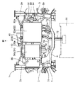
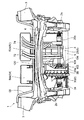
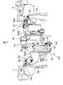
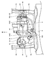
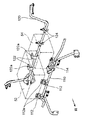
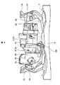
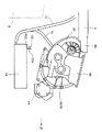
図1および図2は、前記電動車両の前部に形成されたモータルーム1内の構造を示す概略図である。図3〜図6は、後述する駆動ユニット8および電動コンプレッサ40の構造をより明確にするべく、モータルーム1内の構造のうち、後述するインバータ(高電圧部品)52と、車載充電器54と、補機バッテリ56およびこれらの支持構造を省略した図である。図7は、前記インバータ52等の支持構造を示した図である。以下の説明において車幅方向を左右方向(車両前方に向かって右側を右側、前方に向かって左側を左側)といい、車両前後方向を単に前後方向という。
FIG. 1 and FIG. 2 are schematic views showing the structure in the motor room 1 formed in the front part of the electric vehicle. FIGS. 3 to 6 show an inverter (high voltage component) 52, an in-
前記モータルーム1は、図1等に示すように、車室の前方に設けられて左右および上下に延びるダッシュパネル6よりも前方に形成されている。
As shown in FIG. 1 and the like, the motor room 1 is formed in front of a
前記モータルーム1の左右両端には、前後方向に延びる左右一対のフロントサイドフレーム(フレーム部材)2a,2bが設けられている。これらフロントサイドフレーム2a,2bは、後方に向かって略水平に延びた後、ダッシュパネル6近傍で下方に傾斜している。これらフロントサイドフレーム2a,2bのうちモータルーム1内に配置される部分の前後方向中央部分にはビードが形成されており、この部分は他の部分よりも脆弱に構成されている。これらフロントサイドフレーム2a,2bは、後述するように、車両の前突時においてその前端に前方から荷重が加えられると、図8に示すように、前記ビード部分が左右外側に突出する姿勢で折れ曲がり、この変形により衝突荷重を吸収するよう構成されている。なお、図8では、サスクロスメンバ5は破線で示している。
The left and right ends of the motor room 1 are provided with a pair of left and right front side frames (frame members) 2a and 2b extending in the front-rear direction. These
モータルーム1内には、前輪のサスペンションが設けられている。このサスペンションは従来と同様の構造を有しておりその詳細な構造の説明は省略するが、サスペンション本体(不図示)と、図1等に示すように、サスペンション本体を支持するための左右一対のサスペンションタワー3,3およびサスクロスメンバ5を有している。前記サスペンションタワー3は、上方に延びる車体部材であり、前記ダッシュパネル6近傍において前記フロントサイドフレーム2a,2bにそれぞれ取り付けられている。前記サスクロスメンバ5は、モータルーム1の下部であって前記フロントサイドフレーム2a,2b間に配設されている。このサスクロスメンバ5は、前記フロントサイドフレーム2a、2bに固定されている。このサスクロスメンバ5は、前記ダッシュパネル6付近から前方に向かって延びる板状部材であって、左右に延びるサスクロスメンバ本体5aと、このサスクロスメンバ本体5aの左右両前端から前方に向かって突出する突出部5b,5bとを有している。
A front wheel suspension is provided in the motor room 1. This suspension has the same structure as that of the prior art, and a detailed description of the structure is omitted. However, as shown in FIG. 1 and the like, a pair of right and left for supporting the suspension body is provided. Suspension towers 3 and 3 and a
前記モータルーム1内であって、前記フロントサイドフレーム2a,2b間、かつ、前記サスクロスメンバ5よりも上側となる領域には、モータユニット20とトランスアクスル30とからなる駆動ユニット8と、電動コンプレッサ(剛性部材)40と、インバータ52と、車載充電器54と、補機バッテリ56とが設けられている。
In the motor room 1, in a region between the front side frames 2a and 2b and above the
前記モータユニット20は、モータ本体(不図示)と、このモータ本体等を収容するモータユニットハウジング20aとを有する。前記モータ本体は、永久磁石を含み所定の回転軸周りに回転するロータと、このロータの外周に配置されてステータコアにコイルが巻きつけられることで構成されたステータとを有する。前記回転軸の一方端はロータよりも外側に延びておりロータの回転力を外部に伝達するための出力軸を構成している。前記モータユニットハウジング20aは、略円筒状を有し、前記モータ本体はその回転軸とモータユニットハウジング20aの中心軸とが同軸となる姿勢で、このモータユニットハウジング20a内に収容されている。
The
前記トランスアクスル30は、前記モータの出力を車輪に伝達するためのものであり減速機構(トランスミッション)と差動機構とを含む。このトランスアクスル30は、図3および図4に示すように、前記モータユニット20の前記回転軸方向の一方端(出力軸側の端部)に連結部29を介して連結されている。このトランスアクスル30は、前記モータ本体の出力軸に連結されてモータ本体からの回転力が伝達される伝達軸(不図示)と、この回転を減速するための複数のギヤ(不図示)と、車輪に接続されたドライブシャフト4(図2)と連結されるデフ軸(不図示)を含み前記減速されたモータ本体の回転を車輪に伝達するためのデファレンシャルギヤ(不図示)と、これら伝達軸およびギヤを収容するトランスアクスルハウジング38とを有する。このトランスアクスル30は、前記モータ本体の出力軸と前記デフ軸ひいてはドライブシャフト4とが互いに平行となる姿勢で、前記モータユニット20に連結されている。
The
このように構成された前記モータユニット20とトランスアクスル30とを含む駆動ユニット8は、図4に示すように、その駆動軸すなわち前記モータ本体の回転軸およびデフ軸が左右に延びる姿勢で、前記フロントサイドフレーム2a,2bおよび前記サスクロスメンバ5に連結され、これらに支持されている。
As shown in FIG. 4, the
具体的には、前記駆動ユニット8は、左側マウント装置(第1連結機構)80により左側のフロントサイドフレーム2bに連結支持されており、右側マウント装置(第2連結機構)90により右側のフロントサイドフレーム2aに連結支持されており、後側マウント装置(第3連結機構)100により前記サスクロスメンバ4に連結支持されている。
Specifically, the
前記左マウント装置80は、図3および図4に示すように、駆動ユニット8に固定された駆動ユニット側ブラケット82と、左側のフロントサイドフレーム2bに固定された車体側ブラケット84とを有している。前記駆動ユニット側ブラケット82は、トランスアクスルハウジング38の左端上端部分に、上方に突出する状態で固定されている。前記車体側ブラケット84は、前記左側のフロントサイドフレーム2bの上面に上方に突出する状態で固定されている。そして、これら駆動ユニット側ブラケット82と前記車体側ブラケット84とがゴムブッシュを挟んで連結されることで、前記駆動ユニット8の左側上端部は左側のフロントサイドフレーム2bに連結され、駆動ユニット8は左側のフロントサイドフレーム2bにマウント支持(弾性支持)されている。
As shown in FIGS. 3 and 4, the
前記右マウント装置90は、図3および図4に示すように、駆動ユニット8に固定された駆動ユニット側ブラケット92と、右側のフロントサイドフレーム2bに固定された車体側ブラケット94とを有している。前記駆動ユニット側ブラケット92は、前記モータユニットハウジング20aの右端上端部分に、この端部から右側に延びる状態で固定されている。前記車体側ブラケット94は、前記右側のフロントサイドフレーム2aの左側においてこのフロンサイドフレーム2aにその上面よりも上方に突出した状態で固定されている。そして、これら車体側ブラケット94と前記駆動ユニット側ブラケット92の右端部とがゴムブッシュを含むマウント本体(不図示)を挟んで連結されることで、前記駆動ユニット8の右側上端部は前記右側のフロントサイドフレーム2aに連結され、駆動ユニット8は右側のフロントサイドフレーム2aにマウント支持(弾性支持)されている。なお、前記右マウント装置90と左マウント装置80とはほぼ同じ高さに配置されている。
As shown in FIGS. 3 and 4, the
前記右マウント装置90の駆動ユニット側ブラケット92には、その左右中央部分に、その左右外側の部分よりも破断しやすく所定値以上の荷重が加えられることで破断する脆弱部92aが設けられている。この脆弱部92aは、駆動ユニット側ブラケット92のうち前記駆動ユニット8に固定される左側部分と、前記フロントサイドフレーム2aに固定される右側部分との間に介在しており、この脆弱部92aが破断すると駆動ユニット8と前記フロントサイドフレーム2aとの連結は解除される。
The drive
前記後側マウント装置100は、図5に示すように、トルクロッド102と、駆動ユニット側ブラケット104と、サスクロス側ブラケット106と、ゴムブッシュ107,108とを有している。
As shown in FIG. 5, the
前記トルクロッド102は、前記駆動ユニット8の左右方向に延びる軸周りの回動を適切な量に制御するためのものである。すなわち、駆動ユニット8は、前述のようにその左右上端部が弾性支持されることで、加減速等において左右に延びる軸周りに回動可能であるが、前記トルクロッド102はこの回動が過剰になるのを規制する。このトルクロッド102は、板状部材であり、図4および図5に示すように、車幅方向略中央付近において前記トランスアクスルハウジング38の後端下端部からその後方に配置されたサスクロスメンバ5に向かって延びている。
The
前記トランスアクスルハウジング38の後端下端部からは、右側すなわち車幅方向中央側に向かってロッド38aが突出している。前記後側マウント装置100の駆動ユニット側ブラケット104は、このロッド38a近傍に固定されている。前記トルクロッド102の前端は、前記ロッド38aおよび駆動ユニット側ブラケット104により、その左右両側にゴムブッシュ107が取り付けられた状態で、トランスアクスルハウジング38ひいては駆動ユニット8の後端下端部に前記ロッド38aすなわち左右に延びる軸周りに回動可能に固定されている。
A
前記サスクロス側ブラケット106は、前記サスクロスメンバ5の左右中央部分に固定されている。このサスクロス側ブラケット106は、一対の円板部材からなり、左右方向に互いに平行な姿勢で、サスクロスメンバ5の上面から前方かつ上方に突出する姿勢で固定されている。前記トルクロッド102の後端は、このサスクロス側ブラケット106にゴムブッシュ108を介して挟持されており、このサスクロス側ブラケット106を介して前記サスクロスメンバ5に左右に延びる軸周りに回動可能に固定されている。
The suspension
前記オイルパン39は、前記トランスアクスル30の各ギヤに潤滑油として供給されたオイルが流入する部分である。このオイルは、前記各ギヤに供給された後、オイルパン39に流入後、トランスアクスルハウジング38のうちデファレンシャルギヤ側の部分に貯留される。本実施形態では、このオイルパン39は、図5に示すように、略矩形箱状を有し、トランスアクスルハウジング38内のオイルが流入するように、前記トランスアクスルハウジング38の下方にこのトランスアクスルハウジング38の内部と連通した状態で固定されている。このオイルパン39は、図9に示すように、前記トランスアクスルハウジング38の下方に、このトランスアクスルハウジング38の前端付近から前後方向中央付近まで、後方に向かうに従って下方に傾斜した状態で配設されている。また、このオイルパン39は、図5および図9に示すように、その後端部が前記サスクロスメンバ5の突出部5bとほぼ同じ高さ位置であって、通常時にはこの突出部5bから前方に離間する一方、車両の前突時にはその後端部が前記サスクロスメンバ5の突出部5bと当接する位置に配設されている。
The
前記電動コンプレッサ40は、エアコンユニットを構成するものであり、冷媒を膨張させるコンプレッサ本体と、このコンプレッサ本体を収容する略円筒状のコンプレッサケース41とを有している。この電動コンプレッサ40は、図3等に示すように、前記駆動ユニット8よりも小さい。この電動コンプレッサ40は、コンプレッサケース41の中心軸が左右方向に延びる姿勢で、前記モータユニットハウジング20aの外周面前部にブラケット48を介して固定されている。この固定状態において、電動コンプレッサ40の前端は、駆動ユニット8の前端よりも前方に位置し、電動コンプレッサ40の下端は前記駆動ユニット8のうち前記モータユニット20の出力軸すなわち中心軸よりも上方に位置している。また、電動コンプレッサ40は、車幅方向略中央に配設されており、その上端は前記駆動ユニット8の上端よりも上方に位置しているとともに、その前端は前記フロントサイドフレーム2a,2bの前端よりも後方に位置している。
The
前記インバータ52は、車室フロアの下側に設けられた主バッテリ50からの直流電力を交流電力に変換して前記モータ本体に電力を供給するためのものであり、図1および図2に示すように、高電圧の主バッテリ50と第1高電圧ケーブル72により連結されているとともに、モータニット20と第2高電圧ケーブル74により連結されている。このインバータ52は、前記第2高電圧ケーブル74の長さがより短くなるようモータユニット20の上方に配置されている。また、このインバータ52は、後述するように、車両の前突時に電動コンプレッサ40が回動した際にこの電動コンプレッサ40によりその前部が上方に押し上げられる位置に配設されている。このインバータ52は、略矩形箱状のインバータケース52aを有し、インバータ回路はこのインバータケース52aの内側に収容されている。
The
前記第1高電圧ケーブル72は、その長さがより短くなるように、インバータ52の後端左側すなわち左右方向中央であって前記主バッテリ50により近い位置に接続されている。この第1高電圧ケーブル72は、前記インバータ52の後端からこのインバータ52とダッシュパネル6との間で下方に延びた後、ダッシュパネル6の後方に配置された前記主バッテリ50に接続されている。
The first
前記第2高電圧ケーブル74は、前記インバータ52とダッシュパネル6との間に配索されており、前記インバータ52の後端右側から前記ダッシュパネル6の前方で下方に延びた後、前方に湾曲してモータユニット20の右側に接続されている。
The second
前記インバータ52は、図1および図7に示すように、左右のフロントサイドフレーム2a,2bの前端付近にこれらにわたって車幅方向に延びる状態で固定された前側ステー110と、この前側ステー110よりも後方に位置して左右のサスペンションタワー3,3にこれらにわたって車幅方向に延びる状態で固定された後側ステー120とに固定されている。
As shown in FIGS. 1 and 7, the
具体的には、前記前側ステー110には、左右一対の前側インバータ取付部112が固定されている。これら前側インバータ取付部112は、上下方向に延びる取付け面112aを有している。前記インバータ52は、その前面下端部に前記取付面112aが前方から当接してこれらがボルトにより締結されることで、その前端部が前側インバータ取付部112に支持されている。
Specifically, a pair of left and right front
また、前記後側ステー120には、左右一対の後側インバータ取付部122が固定されている。これら後側インバータ取付部122は、後側ステー120から上方に延びて後方に湾曲した後、後方に向かって水平方向に延びる形状を有しており、その上端部に、水平方向に延びる取付面122aを有している。前記インバータ52は、その下面後端部に前記取付面122aが下方から当接してこれらがボルトにより締結されることで、その下面後端部が後側インバータ取付部122により支持されている。
A pair of left and right rear
前記車載充電器54は、車両外部の電源(例えば100V又は200Vの家庭用電源)から電力を入力して前記主バッテリ50を充電するためのものである。この車載充電器54は、図1および図2に示すように、略矩形箱状の充電器ケース54aを有し、この充電器ケース54a内側に充電回路が収容されている。この車載充電器54も前記主バッテリ50と電力ケーブル(不図示)で接続されており、この電力ケーブルの長さがより短くなるように、この車載充電器54は、前記駆動ユニット8の上方であって前記インバータ50の左側の左右方向中央付近に配設されている。
The on-
前記車載充電器54も、前記前側ステー110および後側ステー120に固定されている。具体的には、各ステー110,120に設けられた充電器取付部114,124によりその前端および後端部が支持されている。
The in-
前記補機バッテリ56は、電動パワーステアリング用モータやワイパーモータ等の各種アクチュエータに電力を供給するためのものある。この補機バッテリ56は、図1および図2に示すように、前記駆動ユニット8の左端の上方であって前記車載充電器54の左側に配設されている。この補記バッテリ56は、ブラケット(不図示)により左側のフロントサイドフレーム2bに固定されている。
The
以上のように構成された本電動車両における前突時の作用について説明する。 The operation at the time of a front collision in the electric vehicle configured as described above will be described.
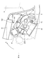
本電動車両では、前述のように、前記電動コンプレッサ40の前端よりもフロントサイドフレーム2a,2bの前端の方が前方に位置している。そのため、車両が前突すると、電動コンプレッサ40よりも先にフロントサイドフレーム2a,2bに後方に向かう衝突荷重が加えられる。この荷重を受けてフロントサイドフレーム2a,2bは、前述のように、そのビード部分を基点とした折れ曲がりを開始する。その後、前記電動コンプレッサ40およびこの電動コンプレッサ40を介して前記駆動ユニット8に後方への荷重が加えられる。ここで、前記電動コンプレッサ40は車幅方向略中央に設けられており、前記駆動ユニット8には、車幅方向にほぼ均一に荷重が加えられる。
In the present electric vehicle, as described above, the front ends of the front side frames 2a and 2b are located in front of the front end of the
前記電動コンプレッサ40は、前述のように、その前端が駆動ユニット8の前端よりも前方に位置し、かつ、その下端が前記駆動ユニット8のうち前記モータユニット20の出力軸すなわち中心軸よりも上方に位置する状態で、前記駆動ユニット8の前部に固定されている。そのため、電動コンプレッサ40に後方への荷重が加えられると、この電動コンプレッサ40を介して、駆動ユニット8には、その前方斜め上方部位に後向きの荷重が加えられる。
As described above, the
前記駆動ユニット8は、前述のように、その左右両端の上端部およびその後側下端部において前記各マウント装置に車幅方向に延びる軸周りに回動可能に支持されている。また、駆動ユニット8が前記荷重を受けて後退するのに伴い前記オイルパン39の後端部は前記サスクロスメンバ5の突出部5bに当接する。そのため、前記のように前方斜め上方部位に後ろ向きの荷重が加えられると、駆動ユニット8は、前記後側マウント装置100および前記オイルパン39の後端部付近すなわちその後側下端部を支点として上方(図10のR方向)に回動し、これに伴い電動コンプレッサ40は後ろ斜め上方へ移動する。ここで、駆動ユニット8に荷重が加えられると前記右側マウント装置90の駆動ユニット側ブラケット92に設けられた脆弱部92aは破断し、右側フロントサイドフレーム2bと駆動ユニット8との連結は解除される。従って、前記駆動ユニット8は容易に上方へ回動する。
As described above, the
前記駆動ユニット8が回動して前記電動コンプレッサ40が後ろ斜め上方へ移動すると、この電動コンプレッサ40および駆動ユニット8に妨害されることなく前記フロントサイドフレーム2a,2bには前方からの荷重が適切に加えられる。そのため、駆動ユニットおよび電動コンプレッサ40の回動とともに、前記フロントサイドフレーム2a,2bはさらに後方(左右外側)へと折れ曲がる。すなわち、電動コンプレッサ40は、容易に変形できない剛性部材として構成されている。そのため、この電動コンプレッサ40が後方に移動しない場合には、前方からの荷重がこの電動コンプレッサ40で受けとめられる結果、フロントサイドフレーム2a,2bに荷重が伝達されずその折れ曲がりが阻害される。これに対して、本電動車両では前記電動コンプレッサ40が後ろ斜め上方へ移動するため、この電動コンプレッサ40の移動とともにフロントサイドフレーム2a,2bに荷重が適切に伝達される。特に、前記脆弱部92aの破断により、右側フロントサイドフレーム2bと駆動ユニット8との連結が解除されており、フロントサイドフレーム2bは、その剛性が小さくされることで容易に折れ曲がる。
When the
また、前記駆動ユニット8が回動して前記電動コンプレッサ40が後ろ斜め上方へ移動すると、前記インバータ52の前端下面にこの電動コンプレッサ40が当接し、インバータ52の前端は電動コンプレッサ40により上方に押し上げられる。前述のように、前記インバータ52は、その下面後端部が前記後側インバータ取付部122により下方から支持されており、その後面は、この後面が後方から支持されている場合に比べて容易に傾斜することができる。そのため、前記インバータ52は、その前端が電動コンプレッサ40により上方に押し上げられると前記後側インバータ取付部122との連結部分を支点として上方に回動する。
When the
以上のように、本電動車両によれば、車両の前突時に電動コンプレッサ40および駆動ユニット8をその後端下端部を支点として上方に回動させることでこの駆動ユニット8に加えられる荷重を分散させてこの駆動ユニット8を介して車室側に加えられる荷重を小さく抑えることができるとともに、電動コンプレッサ40を後ろ斜め上方へ逃がすことでサイドフレーム2a、2bに適切に荷重を伝達させてサイドフレーム2a,2bの変形すなわち荷重の吸収を確実に行い車室側への荷重の伝達を小さく抑えることができる。
As described above, according to the present electric vehicle, the load applied to the
また、車両の前突時に、前記インバータ52がその後端下端部を支点として上方に回動するため、インバータ52が後方に向かって水平方向に移動する場合に比べてその後方への移動量を小さく抑えることができ、このインバータ52の後面に取り付けられた前記第1高電圧ケーブル72および第2高電圧ケーブル74がこの後面と前記ダッシュパネル6との間に挟まり損傷するのを抑制することができる。
ここで、前記オイルパン39の位置は前記に限らない。ただし、駆動ユニット8に取り付けられるオイルパン39を、トランスアクスル38の下方であって前記サスクロスメンバ5に前方から当接する位置すなわちその後端部がサスクロスメンバ5と当接する位置に設ければ、この当接によりオイルパン39の後端を支点として駆動ユニット8を容易に上方に回動させることができる。
Further, at the time of a frontal collision of the vehicle, the
Here, the position of the
また、前記電動コンプレッサ40の車幅方向の位置は前記略中央に限らない。ただし、この位置に設ければ、電動コンプレッサ40ひいては駆動ユニット8により均一に前方からの荷重が加えられるため、これらを適切に回動させることができる。また、例えば、電動コンプレッサ40を車幅方向中央からインバータ52側にオフセットした位置としてもよい。このようにすれば、車両の前突時においてインバータ52を適切に回動させることができる。
Further, the position of the
また、前記右マウント装置90の駆動ユニット側ブラケット92の脆弱部92aは省略可能である。例えば、前記フロントサイドフレーム2a,2bが上方に折れ曲がる場合、すなわち、側面視でくの字型に折れ曲がる場合には、車両の前突時においてフロントサイドフレーム2a,2bと駆動ユニット8との連結を維持しておいたとしても、フロントサイドフレーム2a,2bを駆動ユニット8とともに上方に折れ曲がらせることができるため、前記脆弱部92aを省略してもよい。ただし、前記実施形態のように、フロンとサイドフレーム2a,2bが後方に折れ曲がる場合、すなわち、平面視でくの字型に折れ曲がる場合等には、これらが連結されていることで駆動ユニット8の上方への回動およびフロントサイドフレーム2a,2bの折れ曲がりが妨害されるので、前記脆弱部92aを設けて車両の前突時に前記駆動ユニット8とフロントサイドフレーム2aとの連結を解除するのが好ましい。なお、前記連結を解除するための機構は、破断によりこの連結を解除するという機構に限らない。また、この連結を解除するための機構は、両フロントサイドフレーム2a,2bに設けてもよい。
Further, the weakened
また、前記インバータ52の取り付け構造は前記に限らない。ただし、インバータ52の下面後端部を前記後側インバータ取付部122により下方から支持する構造とすれば、インバータ52をより容易にその下側後端部を支点として上方に回動させることができ、これにより、前記第1高電圧ケーブル72および第2高電圧ケーブル74の損傷を確実に抑制することができる。また、前記インバータ52の代わりあるいはインバータ52とともに前記車載充電器54や補機バッテリ56等に前記電動コンプレッサ40を当接させるようにしてもよい。
Further, the mounting structure of the
また、前記駆動ユニット8の前斜め上方に配設される剛性部材は前記電動コンプレッサ40に限らない。例えば、電動コンプレッサ40の代わりにバキュームポンプやウォータポンプ等を配置してもよい。
Further, the rigid member disposed obliquely above the front of the
1 モータルーム
2 フロントサイドフレーム(フレーム部材)
5 サスクロスメンバ
6 ダッシュパネル
20 モータユニット
30 トランスアクスル(トランスミッション)
40 電動コンプレッサ(剛性部材)
52 インバータ(高電圧部品)
80 左側マウント装置(第1連結機構)
90 右側マウント装置(第2連結機構)
92a 脆弱部
100 後側マウント装置(第3連結機構)
122 後側インバータ取り付け部(保持部材)
1 Motor room 2 Front side frame (frame member)
5
40 Electric compressor (rigid member)
52 Inverter (High voltage component)
80 Left-side mounting device (first coupling mechanism)
90 Right-side mounting device (second coupling mechanism)
92a
122 Rear inverter mounting part (holding member)
Claims (8)
前輪のサスペンションの一部を構成し、前記モータルームの下部に配設されたサスクロスメンバと、
前記駆動ユニットの車幅方向両外側に設けられて車両前後方向に延びる一対のフレーム部材と、
前記駆動ユニットの車幅方向一方側の上端部と当該車幅方向一方側に配設された前記フレーム部材とを連結する第1連結機構と、
前記駆動ユニットの車幅方向他方側の上端部と当該車幅方向他方側に配設された前記フレーム部材とを連結する第2連結機構と、
前記駆動ユニットの後側、かつ、下側部分と前記サスクロスメンバとを連結する第3連結機構と、
前端が前記駆動ユニットの前端よりも前方に位置する状態で当該駆動ユニットに取り付けられた剛性部材とを備え、
前記剛性部材は、車両の前突時に当該剛性部材を介して前記駆動ユニットのうち前記出力軸よりも上側の部分に衝突荷重が加えられるように、その下端が前記モータの出力軸よりも上方に位置する状態で前記駆動ユニットに取り付けられており、
前記各連結機構は、車両の前突時に前記剛性部材を介して前記駆動ユニットのうち前記出力軸よりも上側の部分に前方から衝突荷重が加えられた際に、当該駆動ユニットが前記第3連結機構を支点として上方に回動しつつ後方に移動するよう当該駆動ユニットと前記フレーム部材および前記サスクロスメンバとを連結していることを特徴とする電動車両。 A drive unit including a motor unit including a motor having an output shaft extending from a rotation shaft and a transmission coupled to the motor unit in a motor room formed in a front portion of the vehicle, wherein the output shaft is a vehicle width In the electric vehicle that extends in the direction and is arranged in a posture in which the transmission is positioned at one end in the vehicle width direction of the motor unit,
A part of the suspension of the front wheel, a suspension cross member disposed at the bottom of the motor room;
A pair of frame members provided on both outer sides in the vehicle width direction of the drive unit and extending in the vehicle front-rear direction;
A first connection mechanism that connects an upper end portion on one side in the vehicle width direction of the drive unit and the frame member disposed on one side in the vehicle width direction;
A second connection mechanism that connects the upper end of the drive unit on the other side in the vehicle width direction and the frame member disposed on the other side in the vehicle width direction;
A third connection mechanism that connects the rear side of the drive unit and the lower portion to the suspension cross member;
A rigid member attached to the drive unit in a state where the front end is located forward of the front end of the drive unit;
The rigid member has a lower end above the output shaft of the motor so that a collision load is applied to a portion of the drive unit above the output shaft through the rigid member during a frontal collision of the vehicle. It is attached to the drive unit in a positioned state,
Each of the connection mechanisms is configured such that when a collision load is applied from the front to a portion of the drive unit above the output shaft through the rigid member during a frontal collision of the vehicle, the drive unit is connected to the third connection. An electric vehicle characterized in that the drive unit, the frame member, and the suspension cross member are connected so as to move backward while rotating upward with a mechanism as a fulcrum.
前記トランスミッションの下方に取り付けられたオイルパンを備え、
前記オイルパンは、車両の前突時に前記駆動ユニットが後方に移動するのに伴ってその後端が前記サスクロスメンバに前方から当接する位置に配設されていることを特徴とする電動車両。 The electric vehicle according to claim 1,
An oil pan attached below the transmission;
The electric vehicle is characterized in that the oil pan is disposed at a position where a rear end of the oil pan comes into contact with the suspension cross member from the front as the drive unit moves rearward during a frontal collision of the vehicle.
前記剛性部材は、車幅方向略中央に配設されていることを特徴とする電動車両。 The electric vehicle according to claim 1 or 2,
The electric vehicle according to claim 1, wherein the rigid member is disposed substantially in the center in the vehicle width direction.
前記駆動ユニットの上方に配設されて少なくともその後端部分が車体部材により保持された高電圧部品と、当該高電圧部品の後端部に接続された高電圧配線とを備え、
前記高電圧部品は、車両の前突時に前記駆動ユニットおよび当該駆動ユニットに取り付けられた前記剛性部材が上方に回動した際に、前記剛性部材が当該高電圧部品の前部に下方から当接する位置に配設されていることを特徴とする電動車両。 In the electric vehicle according to any one of claims 1 to 3,
A high voltage component disposed above the drive unit and having at least a rear end portion thereof held by a vehicle body member, and a high voltage wiring connected to a rear end portion of the high voltage component;
When the drive unit and the rigid member attached to the drive unit rotate upward during a frontal collision of the vehicle, the high-voltage component contacts the front portion of the high-voltage component from below. An electric vehicle characterized by being disposed at a position.
車体部材に固定されて前記高電圧部品を保持するための保持部材を備え、
前記保持部材は、前記高電圧部品の下面の後端部を下方から保持していることを特徴とする電動車両。 The electric vehicle according to claim 4,
A holding member for holding the high voltage component fixed to a vehicle body member;
The electric vehicle according to claim 1, wherein the holding member holds a rear end portion of the lower surface of the high-voltage component from below.
前記第1連結機構と第2連結機構の少なくとも一方は、車両の前突時に前記駆動ユニットに前方から荷重が加えられるのに伴って前記駆動ユニットと前記フレーム部材との連結を解除可能であることを特徴とする電動車両。 In the electric vehicle according to any one of claims 1 to 5,
At least one of the first connection mechanism and the second connection mechanism is capable of releasing the connection between the drive unit and the frame member as a load is applied to the drive unit from the front during a frontal collision of the vehicle. An electric vehicle characterized by
前記第1連結機構と第2連結機構の少なくとも一方は、車両の前突時に前記駆動ユニットに前方からの衝突荷重が加えられるのに伴って破断する脆弱部を有し、当該脆弱部の破断により前記駆動ユニットと前記フレーム部材との連結を解除することを特徴とする電動車両。 The electric vehicle according to claim 6,
At least one of the first coupling mechanism and the second coupling mechanism has a fragile portion that breaks when a collision load from the front is applied to the drive unit during a frontal collision of the vehicle. An electric vehicle characterized in that the connection between the drive unit and the frame member is released.
前記剛性部材は電動コンプレッサであることを特徴とする電動車両。 In the electric vehicle according to any one of claims 1 to 7,
The electric vehicle characterized in that the rigid member is an electric compressor.
Priority Applications (1)
| Application Number | Priority Date | Filing Date | Title |
|---|---|---|---|
| JP2011003858A JP5494499B2 (en) | 2011-01-12 | 2011-01-12 | Electric vehicle |
Applications Claiming Priority (1)
| Application Number | Priority Date | Filing Date | Title |
|---|---|---|---|
| JP2011003858A JP5494499B2 (en) | 2011-01-12 | 2011-01-12 | Electric vehicle |
Publications (2)
| Publication Number | Publication Date |
|---|---|
| JP2012144142A true JP2012144142A (en) | 2012-08-02 |
| JP5494499B2 JP5494499B2 (en) | 2014-05-14 |
Family
ID=46788190
Family Applications (1)
| Application Number | Title | Priority Date | Filing Date |
|---|---|---|---|
| JP2011003858A Expired - Fee Related JP5494499B2 (en) | 2011-01-12 | 2011-01-12 | Electric vehicle |
Country Status (1)
| Country | Link |
|---|---|
| JP (1) | JP5494499B2 (en) |
Cited By (25)
| Publication number | Priority date | Publication date | Assignee | Title |
|---|---|---|---|---|
| JP2012206582A (en) * | 2011-03-29 | 2012-10-25 | Toyota Motor Corp | Electric vehicle |
| WO2014148410A1 (en) * | 2013-03-18 | 2014-09-25 | 日立オートモティブシステムズ株式会社 | Drive device for electric vehicle |
| WO2015083698A1 (en) | 2013-12-02 | 2015-06-11 | 本田技研工業株式会社 | Vehicle |
| JP2016002960A (en) * | 2014-06-19 | 2016-01-12 | スズキ株式会社 | Protective structure for vehicle electrical equipment |
| EP3023281A4 (en) * | 2013-07-18 | 2016-08-10 | Nissan Motor | Hybrid vehicle |
| JP2016203902A (en) * | 2015-04-27 | 2016-12-08 | 三菱自動車工業株式会社 | Wiring fixing structure of vehicle |
| JP2018114786A (en) * | 2017-01-16 | 2018-07-26 | マツダ株式会社 | Electric vehicle |
| CN109263456A (en) * | 2017-07-14 | 2019-01-25 | 丰田自动车株式会社 | Body structure |
| CN110315952A (en) * | 2019-06-15 | 2019-10-11 | 江苏开沃汽车有限公司 | A kind of suspension of driving motor and compressor integration installation structure |
| WO2019197857A1 (en) * | 2018-04-12 | 2019-10-17 | 日産自動車株式会社 | Vehicle front-arrangement structure and vehicle equipped with vehicle front-arrangement structure |
| JP2020026219A (en) * | 2018-08-10 | 2020-02-20 | トヨタ自動車株式会社 | Vehicle front structure |
| JP2020032954A (en) * | 2018-08-31 | 2020-03-05 | スズキ株式会社 | Motor unit support structure |
| JP2020037313A (en) * | 2018-09-03 | 2020-03-12 | トヨタ自動車株式会社 | Power unit room structure for vehicle |
| JP2020199892A (en) * | 2019-06-11 | 2020-12-17 | 本田技研工業株式会社 | Electric vehicle |
| JP2021003939A (en) * | 2019-06-25 | 2021-01-14 | スズキ株式会社 | Front part structure of vehicle |
| JP2021011165A (en) * | 2019-07-05 | 2021-02-04 | 三菱自動車工業株式会社 | Mount structure of power plant to vehicle body |
| JP2021030833A (en) * | 2019-08-22 | 2021-03-01 | マツダ株式会社 | Vehicle front structure |
| CN112996683A (en) * | 2018-10-04 | 2021-06-18 | 艾里逊变速箱公司 | Electric axle assembly for low-chassis vehicle |
| CN113853320A (en) * | 2019-05-07 | 2021-12-28 | 株式会社斯巴鲁 | Power unit suspension structure |
| KR102347766B1 (en) * | 2020-09-14 | 2022-01-05 | 현대자동차주식회사 | Drive motor module for vehicle |
| US11305628B2 (en) | 2019-04-25 | 2022-04-19 | Toyota Jidosha Kabushiki Kaisha | Electric vehicle |
| JPWO2023007978A1 (en) * | 2021-07-27 | 2023-02-02 | ||
| CN116461310A (en) * | 2022-01-18 | 2023-07-21 | 丰田自动车株式会社 | electric vehicle |
| JP2023184359A (en) * | 2022-06-17 | 2023-12-28 | 本田技研工業株式会社 | Vehicle high voltage equipment mounting structure |
| JP2024136034A (en) * | 2023-03-23 | 2024-10-04 | ダイハツ工業株式会社 | Electric compressor mounted structure |
Families Citing this family (1)
| Publication number | Priority date | Publication date | Assignee | Title |
|---|---|---|---|---|
| JP6521757B2 (en) | 2015-06-17 | 2019-05-29 | 本田技研工業株式会社 | Electric vehicle |
Citations (5)
| Publication number | Priority date | Publication date | Assignee | Title |
|---|---|---|---|---|
| JP2002127762A (en) * | 2000-10-23 | 2002-05-08 | Kobe Steel Ltd | Engine mount |
| JP2002200924A (en) * | 2000-12-28 | 2002-07-16 | Mazda Motor Corp | Power plant support structure |
| JP2004161260A (en) * | 2002-10-21 | 2004-06-10 | Nissan Motor Co Ltd | Drive motor mounting structure |
| JP2006219020A (en) * | 2005-02-10 | 2006-08-24 | Nissan Motor Co Ltd | Motor room component mounting structure and motor room shock absorption structure |
| JP2009286287A (en) * | 2008-05-29 | 2009-12-10 | Toyota Motor Corp | Mounting structure |
-
2011
- 2011-01-12 JP JP2011003858A patent/JP5494499B2/en not_active Expired - Fee Related
Patent Citations (5)
| Publication number | Priority date | Publication date | Assignee | Title |
|---|---|---|---|---|
| JP2002127762A (en) * | 2000-10-23 | 2002-05-08 | Kobe Steel Ltd | Engine mount |
| JP2002200924A (en) * | 2000-12-28 | 2002-07-16 | Mazda Motor Corp | Power plant support structure |
| JP2004161260A (en) * | 2002-10-21 | 2004-06-10 | Nissan Motor Co Ltd | Drive motor mounting structure |
| JP2006219020A (en) * | 2005-02-10 | 2006-08-24 | Nissan Motor Co Ltd | Motor room component mounting structure and motor room shock absorption structure |
| JP2009286287A (en) * | 2008-05-29 | 2009-12-10 | Toyota Motor Corp | Mounting structure |
Cited By (45)
| Publication number | Priority date | Publication date | Assignee | Title |
|---|---|---|---|---|
| JP2012206582A (en) * | 2011-03-29 | 2012-10-25 | Toyota Motor Corp | Electric vehicle |
| WO2014148410A1 (en) * | 2013-03-18 | 2014-09-25 | 日立オートモティブシステムズ株式会社 | Drive device for electric vehicle |
| CN105073464A (en) * | 2013-03-18 | 2015-11-18 | 日立汽车系统株式会社 | Drive device for electric vehicle |
| JPWO2014148410A1 (en) * | 2013-03-18 | 2017-02-16 | 日立オートモティブシステムズ株式会社 | Electric vehicle drive |
| EP3023281A4 (en) * | 2013-07-18 | 2016-08-10 | Nissan Motor | Hybrid vehicle |
| WO2015083698A1 (en) | 2013-12-02 | 2015-06-11 | 本田技研工業株式会社 | Vehicle |
| KR20160093002A (en) | 2013-12-02 | 2016-08-05 | 혼다 기켄 고교 가부시키가이샤 | Vehicle |
| US9764644B2 (en) | 2013-12-02 | 2017-09-19 | Honda Motor Co., Ltd. | Vehicle |
| JP2016002960A (en) * | 2014-06-19 | 2016-01-12 | スズキ株式会社 | Protective structure for vehicle electrical equipment |
| JP2016203902A (en) * | 2015-04-27 | 2016-12-08 | 三菱自動車工業株式会社 | Wiring fixing structure of vehicle |
| JP2018114786A (en) * | 2017-01-16 | 2018-07-26 | マツダ株式会社 | Electric vehicle |
| CN109263456B (en) * | 2017-07-14 | 2021-03-26 | 丰田自动车株式会社 | Body structure |
| CN109263456A (en) * | 2017-07-14 | 2019-01-25 | 丰田自动车株式会社 | Body structure |
| JPWO2019197857A1 (en) * | 2018-04-12 | 2021-02-12 | 日産自動車株式会社 | Vehicle front arrangement structure and vehicle equipped with the vehicle front arrangement structure |
| WO2019197857A1 (en) * | 2018-04-12 | 2019-10-17 | 日産自動車株式会社 | Vehicle front-arrangement structure and vehicle equipped with vehicle front-arrangement structure |
| JP7055196B2 (en) | 2018-04-12 | 2022-04-15 | 日産自動車株式会社 | Vehicle front arrangement structure and vehicle equipped with the vehicle front arrangement structure |
| JP2020026219A (en) * | 2018-08-10 | 2020-02-20 | トヨタ自動車株式会社 | Vehicle front structure |
| JP7196455B2 (en) | 2018-08-10 | 2022-12-27 | トヨタ自動車株式会社 | vehicle front structure |
| JP2020032954A (en) * | 2018-08-31 | 2020-03-05 | スズキ株式会社 | Motor unit support structure |
| JP7180214B2 (en) | 2018-08-31 | 2022-11-30 | スズキ株式会社 | Motor unit support structure |
| JP7063203B2 (en) | 2018-09-03 | 2022-05-09 | トヨタ自動車株式会社 | Vehicle power unit room structure |
| US11524561B2 (en) | 2018-09-03 | 2022-12-13 | Toyota Jidosha Kabushiki Kaisha | Vehicle power unit room structure |
| JP2020037313A (en) * | 2018-09-03 | 2020-03-12 | トヨタ自動車株式会社 | Power unit room structure for vehicle |
| CN112996683A (en) * | 2018-10-04 | 2021-06-18 | 艾里逊变速箱公司 | Electric axle assembly for low-chassis vehicle |
| US11305628B2 (en) | 2019-04-25 | 2022-04-19 | Toyota Jidosha Kabushiki Kaisha | Electric vehicle |
| CN113853320A (en) * | 2019-05-07 | 2021-12-28 | 株式会社斯巴鲁 | Power unit suspension structure |
| JP2020199892A (en) * | 2019-06-11 | 2020-12-17 | 本田技研工業株式会社 | Electric vehicle |
| CN110315952A (en) * | 2019-06-15 | 2019-10-11 | 江苏开沃汽车有限公司 | A kind of suspension of driving motor and compressor integration installation structure |
| JP2021003939A (en) * | 2019-06-25 | 2021-01-14 | スズキ株式会社 | Front part structure of vehicle |
| JP7238629B2 (en) | 2019-06-25 | 2023-03-14 | スズキ株式会社 | vehicle front structure |
| JP2021011165A (en) * | 2019-07-05 | 2021-02-04 | 三菱自動車工業株式会社 | Mount structure of power plant to vehicle body |
| JP7276687B2 (en) | 2019-08-22 | 2023-05-18 | マツダ株式会社 | vehicle front structure |
| JP2021030833A (en) * | 2019-08-22 | 2021-03-01 | マツダ株式会社 | Vehicle front structure |
| KR102347766B1 (en) * | 2020-09-14 | 2022-01-05 | 현대자동차주식회사 | Drive motor module for vehicle |
| WO2023007978A1 (en) * | 2021-07-27 | 2023-02-02 | 三菱自動車工業株式会社 | Vehicular mount apparatus |
| JPWO2023007978A1 (en) * | 2021-07-27 | 2023-02-02 | ||
| JP7529162B2 (en) | 2021-07-27 | 2024-08-06 | 三菱自動車工業株式会社 | Vehicle Mounting Device |
| CN116461310A (en) * | 2022-01-18 | 2023-07-21 | 丰田自动车株式会社 | electric vehicle |
| JP2023104736A (en) * | 2022-01-18 | 2023-07-28 | トヨタ自動車株式会社 | electric vehicle |
| JP7647600B2 (en) | 2022-01-18 | 2025-03-18 | トヨタ自動車株式会社 | Electric vehicles |
| US12280652B2 (en) | 2022-01-18 | 2025-04-22 | Toyota Jidosha Kabushiki Kaisha | Electrified vehicle power system arrangement |
| JP2023184359A (en) * | 2022-06-17 | 2023-12-28 | 本田技研工業株式会社 | Vehicle high voltage equipment mounting structure |
| JP7483793B2 (en) | 2022-06-17 | 2024-05-15 | 本田技研工業株式会社 | High voltage device mounting structure for vehicle |
| JP2024136034A (en) * | 2023-03-23 | 2024-10-04 | ダイハツ工業株式会社 | Electric compressor mounted structure |
| JP7711119B2 (en) | 2023-03-23 | 2025-07-22 | ダイハツ工業株式会社 | Electric compressor mounted structure |
Also Published As
| Publication number | Publication date |
|---|---|
| JP5494499B2 (en) | 2014-05-14 |
Similar Documents
| Publication | Publication Date | Title |
|---|---|---|
| JP5494499B2 (en) | Electric vehicle | |
| CN112895921B (en) | Electric vehicle drive system | |
| KR100899266B1 (en) | Electric motor mounting structure for vehicles | |
| JP5589766B2 (en) | Parts mounting structure in the motor room of electric vehicles | |
| JP5924692B2 (en) | Motor vehicle equipped with electric power train and power supply module thereof arranged in the vicinity of vehicle axle | |
| US11383592B2 (en) | Mounting structure for drive device in series hybrid vehicle | |
| JP5561156B2 (en) | Electric vehicle | |
| JP6119790B2 (en) | Holding mechanism, electric vehicle, front wheel drive electric vehicle, and rear wheel drive electric vehicle | |
| CN102085797B (en) | Attachment structure of electromotor of hybrid vehicle | |
| JP5691559B2 (en) | Mounting structure of electric junction box for vehicles | |
| JP2012096587A (en) | Electrical component mounting structure of electric vehicle | |
| JP2008081009A (en) | Vehicle motor mount structure | |
| JP2004161260A (en) | Drive motor mounting structure | |
| CN109515143B (en) | electric vehicle | |
| JP6620763B2 (en) | Electric vehicle | |
| JP5338642B2 (en) | Motor mounting structure | |
| JP2019151174A (en) | Arrangement structure of power source unit in electric vehicle | |
| JP2019055765A (en) | Electric vehicle | |
| JP4345795B2 (en) | Vehicle motor mount structure | |
| JP2019077355A (en) | On-vehicle structure of power control device | |
| EP4309936A1 (en) | Structure for mounting electric unit to vehicle | |
| JP2017100611A (en) | On-vehicle structure of electric power control device | |
| JP5488409B2 (en) | Power unit support device for electric vehicle | |
| JP5929749B2 (en) | On-board equipment mounting structure | |
| JP2015166581A (en) | Vehicular generating device |
Legal Events
| Date | Code | Title | Description |
|---|---|---|---|
| A621 | Written request for application examination |
Free format text: JAPANESE INTERMEDIATE CODE: A621 Effective date: 20130313 |
|
| TRDD | Decision of grant or rejection written | ||
| A977 | Report on retrieval |
Free format text: JAPANESE INTERMEDIATE CODE: A971007 Effective date: 20140130 |
|
| A01 | Written decision to grant a patent or to grant a registration (utility model) |
Free format text: JAPANESE INTERMEDIATE CODE: A01 Effective date: 20140204 |
|
| A61 | First payment of annual fees (during grant procedure) |
Free format text: JAPANESE INTERMEDIATE CODE: A61 Effective date: 20140217 |
|
| R150 | Certificate of patent or registration of utility model |
Ref document number: 5494499 Country of ref document: JP Free format text: JAPANESE INTERMEDIATE CODE: R150 |
|
| LAPS | Cancellation because of no payment of annual fees |