JP2012120362A - Dc−dcコンバータ - Google Patents
Dc−dcコンバータ Download PDFInfo
- Publication number
- JP2012120362A JP2012120362A JP2010269162A JP2010269162A JP2012120362A JP 2012120362 A JP2012120362 A JP 2012120362A JP 2010269162 A JP2010269162 A JP 2010269162A JP 2010269162 A JP2010269162 A JP 2010269162A JP 2012120362 A JP2012120362 A JP 2012120362A
- Authority
- JP
- Japan
- Prior art keywords
- switching element
- reactor
- circuit
- voltage
- current
- Prior art date
- Legal status (The legal status is an assumption and is not a legal conclusion. Google has not performed a legal analysis and makes no representation as to the accuracy of the status listed.)
- Pending
Links
- 239000003990 capacitor Substances 0.000 claims abstract description 44
- 238000009499 grossing Methods 0.000 claims abstract description 27
- 238000010586 diagram Methods 0.000 description 14
- 230000003071 parasitic effect Effects 0.000 description 12
- 101100033865 Saccharomyces cerevisiae (strain ATCC 204508 / S288c) RFA1 gene Proteins 0.000 description 8
- 101100524516 Saccharomyces cerevisiae (strain ATCC 204508 / S288c) RFA2 gene Proteins 0.000 description 7
- 230000000694 effects Effects 0.000 description 3
- 230000007423 decrease Effects 0.000 description 2
- 238000011084 recovery Methods 0.000 description 2
- 230000000630 rising effect Effects 0.000 description 2
- 239000004065 semiconductor Substances 0.000 description 2
- 230000001052 transient effect Effects 0.000 description 2
- 230000000295 complement effect Effects 0.000 description 1
- 238000007796 conventional method Methods 0.000 description 1
- 108010017036 dynorphin A-converting enzyme Proteins 0.000 description 1
- 238000000034 method Methods 0.000 description 1
- 230000001360 synchronised effect Effects 0.000 description 1
- 230000007704 transition Effects 0.000 description 1
Images


Classifications
-
- H—ELECTRICITY
- H02—GENERATION; CONVERSION OR DISTRIBUTION OF ELECTRIC POWER
- H02M—APPARATUS FOR CONVERSION BETWEEN AC AND AC, BETWEEN AC AND DC, OR BETWEEN DC AND DC, AND FOR USE WITH MAINS OR SIMILAR POWER SUPPLY SYSTEMS; CONVERSION OF DC OR AC INPUT POWER INTO SURGE OUTPUT POWER; CONTROL OR REGULATION THEREOF
- H02M3/00—Conversion of DC power input into DC power output
- H02M3/02—Conversion of DC power input into DC power output without intermediate conversion into AC
- H02M3/04—Conversion of DC power input into DC power output without intermediate conversion into AC by static converters
- H02M3/10—Conversion of DC power input into DC power output without intermediate conversion into AC by static converters using discharge tubes with control electrode or semiconductor devices with control electrode
- H02M3/145—Conversion of DC power input into DC power output without intermediate conversion into AC by static converters using discharge tubes with control electrode or semiconductor devices with control electrode using devices of a triode or transistor type requiring continuous application of a control signal
- H02M3/155—Conversion of DC power input into DC power output without intermediate conversion into AC by static converters using discharge tubes with control electrode or semiconductor devices with control electrode using devices of a triode or transistor type requiring continuous application of a control signal using semiconductor devices only
- H02M3/156—Conversion of DC power input into DC power output without intermediate conversion into AC by static converters using discharge tubes with control electrode or semiconductor devices with control electrode using devices of a triode or transistor type requiring continuous application of a control signal using semiconductor devices only with automatic control of output voltage or current, e.g. switching regulators
- H02M3/158—Conversion of DC power input into DC power output without intermediate conversion into AC by static converters using discharge tubes with control electrode or semiconductor devices with control electrode using devices of a triode or transistor type requiring continuous application of a control signal using semiconductor devices only with automatic control of output voltage or current, e.g. switching regulators including plural semiconductor devices as final control devices for a single load
- H02M3/1588—Conversion of DC power input into DC power output without intermediate conversion into AC by static converters using discharge tubes with control electrode or semiconductor devices with control electrode using devices of a triode or transistor type requiring continuous application of a control signal using semiconductor devices only with automatic control of output voltage or current, e.g. switching regulators including plural semiconductor devices as final control devices for a single load comprising at least one synchronous rectifier element
-
- H—ELECTRICITY
- H02—GENERATION; CONVERSION OR DISTRIBUTION OF ELECTRIC POWER
- H02M—APPARATUS FOR CONVERSION BETWEEN AC AND AC, BETWEEN AC AND DC, OR BETWEEN DC AND DC, AND FOR USE WITH MAINS OR SIMILAR POWER SUPPLY SYSTEMS; CONVERSION OF DC OR AC INPUT POWER INTO SURGE OUTPUT POWER; CONTROL OR REGULATION THEREOF
- H02M1/00—Details of apparatus for conversion
- H02M1/0003—Details of control, feedback or regulation circuits
- H02M1/0032—Control circuits allowing low power mode operation, e.g. in standby mode
-
- Y—GENERAL TAGGING OF NEW TECHNOLOGICAL DEVELOPMENTS; GENERAL TAGGING OF CROSS-SECTIONAL TECHNOLOGIES SPANNING OVER SEVERAL SECTIONS OF THE IPC; TECHNICAL SUBJECTS COVERED BY FORMER USPC CROSS-REFERENCE ART COLLECTIONS [XRACs] AND DIGESTS
- Y02—TECHNOLOGIES OR APPLICATIONS FOR MITIGATION OR ADAPTATION AGAINST CLIMATE CHANGE
- Y02B—CLIMATE CHANGE MITIGATION TECHNOLOGIES RELATED TO BUILDINGS, e.g. HOUSING, HOUSE APPLIANCES OR RELATED END-USER APPLICATIONS
- Y02B70/00—Technologies for an efficient end-user side electric power management and consumption
- Y02B70/10—Technologies improving the efficiency by using switched-mode power supplies [SMPS], i.e. efficient power electronics conversion e.g. power factor correction or reduction of losses in power supplies or efficient standby modes
Landscapes
- Engineering & Computer Science (AREA)
- Power Engineering (AREA)
- Dc-Dc Converters (AREA)
Abstract
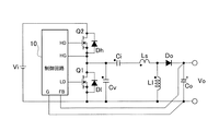
【解決手段】直流電源Vinの両端に接続され、第1スイッチング素子Q1と第2スイッチング素子Q2とが直列に接続された第1直列回路と、第1スイッチング素子及び第2スイッチング素子を交互にオン・オフさせる制御回路10と、第1スイッチング素子の両端に接続され、第1コンデンサCiと第1リアクトルLsと第1リアクトルの値よりも大きい第2リアクトルLlとが直列に接続された第2直列回路と、第2リアクトルの両端電圧を整流平滑して直流出力電圧を取り出す整流平滑回路Do,Coとを有する。
【選択図】図1
Description
Vron=リアクトル電流IL×スイッチング素子Q1のオン抵抗Ron
となるので、オン抵抗Ronの小さなMOS−FETを選定することにより、寄生ダイオードのVfより小さい飽和電圧となり、スイッチング素子Q1がオン時の損失が低減される。

Vo≒Vi−VCi
Vo≒Vi×DQ1 (DQ1は、Q1のオン比率) (1)
と表わせる。式(1)から、負荷電流と出力電圧Voは、直接関係が無く、負荷電流の変化に対してスイッチング素子Q1とスイッチング素子Q2とのオン・オフ比率はほとんど変化しない。実際の回路ではラインドロップや半導体素子の抵抗分などによる電圧降下が発生するため、これらを補うために僅かにオン・オフ比率が変化する。
Vo≒VCi
Vo≒Vi×DQ2 (DQ2は、Q2のオン比率) (2)
と表わせる。式(2)から、負荷電流と出力電圧は、直接関係が無く、負荷電流の変化に対してスイッチング素子Q1とQ2のオン・オフ比率はほとんど変化しない。実際の回路ではラインドロップや半導体素子の抵抗分などによる電圧降下が発生するため、これらを補うために僅かにオン・オフ比率が変化する。
Q1,Q2 スイッチング素子
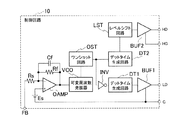
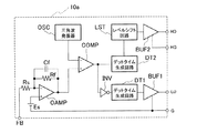
10,10a,10b,11 制御回路
Ci,Cf コンデンサ
Cv 電圧共振コンデンサ
Ll,Ls リアクトル
Do ダイオード
Co 平滑コンデンサ
OAMP オペアンプ
OST ワンショット回路
INV インバータ
DT1,DT2 デットタイム生成回路
BUF1,BUF2 バッファ回路
LST レベルシフト回路
VCO 可変周波数発振器
Rs,Ra,Rb,Rc,Rf 抵抗
Claims (5)
- 直流電源の両端に接続され、第1スイッチング素子と第2スイッチング素子とが直列に接続された第1直列回路と、
前記第1スイッチング素子及び前記第2スイッチング素子を交互にオン・オフさせる制御回路と、
前記第1スイッチング素子の両端に接続され、第1コンデンサと第1リアクトルと前記第1リアクトルの値よりも大きい第2リアクトルとが直列に接続された第2直列回路と、
前記第2リアクトルの両端電圧を整流平滑して直流出力電圧を取り出す整流平滑回路と、
を有することを特徴とするDC−DCコンバータ。 - 前記整流平滑回路は、整流素子と平滑素子とからなる半波整流平滑回路であることを特徴とする請求項1記載のDC−DCコンバータ。
- 前記第2リアクトルの一端が、前記直流電源の一端に接続されていることを特徴とする請求項1又は請求項2記載のDC−DCコンバータ。
- 前記直流電源の一端と前記直流出力電圧の一端が、それぞれ同一極性により接続されることを特徴とする請求項1又は請求項2記載のDC−DCコンバータ。
- 前記直流電源の一端と前記直流出力電圧の一端が、それぞれ逆極性により接続されることを特徴とする請求項1又は請求項2記載のDC−DCコンバータ。
Priority Applications (2)
| Application Number | Priority Date | Filing Date | Title |
|---|---|---|---|
| JP2010269162A JP2012120362A (ja) | 2010-12-02 | 2010-12-02 | Dc−dcコンバータ |
| US13/304,919 US8648577B2 (en) | 2010-12-02 | 2011-11-28 | DC-DC converter |
Applications Claiming Priority (1)
| Application Number | Priority Date | Filing Date | Title |
|---|---|---|---|
| JP2010269162A JP2012120362A (ja) | 2010-12-02 | 2010-12-02 | Dc−dcコンバータ |
Publications (1)
| Publication Number | Publication Date |
|---|---|
| JP2012120362A true JP2012120362A (ja) | 2012-06-21 |
Family
ID=46161616
Family Applications (1)
| Application Number | Title | Priority Date | Filing Date |
|---|---|---|---|
| JP2010269162A Pending JP2012120362A (ja) | 2010-12-02 | 2010-12-02 | Dc−dcコンバータ |
Country Status (2)
| Country | Link |
|---|---|
| US (1) | US8648577B2 (ja) |
| JP (1) | JP2012120362A (ja) |
Cited By (5)
| Publication number | Priority date | Publication date | Assignee | Title |
|---|---|---|---|---|
| JP2017112679A (ja) * | 2015-12-15 | 2017-06-22 | 田淵電機株式会社 | 非絶縁型複合共振dc−dcコンバータ |
| JP6215510B1 (ja) * | 2016-11-11 | 2017-10-18 | 新電元工業株式会社 | Mosfet及び電力変換回路 |
| WO2018087943A1 (ja) * | 2016-11-11 | 2018-05-17 | 新電元工業株式会社 | Mosfet及び電力変換回路 |
| JP6362154B1 (ja) * | 2017-05-26 | 2018-07-25 | 新電元工業株式会社 | Mosfet及び電力変換回路 |
| TWI692924B (zh) * | 2017-11-17 | 2020-05-01 | 日商新電元工業股份有限公司 | 電力轉換電路 |
Families Citing this family (4)
| Publication number | Priority date | Publication date | Assignee | Title |
|---|---|---|---|---|
| FR2998735B1 (fr) * | 2012-11-27 | 2022-10-07 | Hispano Suiza Sa | Convertisseur de tension continu-continu a haute tension |
| TWI538373B (zh) * | 2013-05-24 | 2016-06-11 | 中心微電子德累斯頓股份公司 | 切換式功率轉換器以及用於控制切換式功率轉換器的方法 |
| US9991794B2 (en) * | 2016-03-22 | 2018-06-05 | Texas Instruments Incorporated | Hybrid capacitive-inductive voltage converter |
| CN113507208B (zh) * | 2021-06-30 | 2022-07-22 | 中国科学技术大学 | 多相串联电容直流-直流转换器、控制方法 |
Citations (4)
| Publication number | Priority date | Publication date | Assignee | Title |
|---|---|---|---|---|
| JPH0295168A (ja) * | 1988-10-18 | 1990-04-05 | Nippon Telegr & Teleph Corp <Ntt> | Dc−dc変換回路 |
| JP2005524375A (ja) * | 2002-04-23 | 2005-08-11 | コーニンクレッカ フィリップス エレクトロニクス エヌ ヴィ | Llcハーフブリッジコンバータ |
| JP2006187159A (ja) * | 2004-12-28 | 2006-07-13 | Mitsumi Electric Co Ltd | 共振型スイッチング電源装置 |
| JP2008507946A (ja) * | 2004-07-21 | 2008-03-13 | コーニンクレッカ フィリップス エレクトロニクス エヌ ヴィ | 直列共振スイッチモード電源装置のための自動周波数制御 |
Family Cites Families (9)
| Publication number | Priority date | Publication date | Assignee | Title |
|---|---|---|---|---|
| US5481238A (en) * | 1994-04-19 | 1996-01-02 | Argus Technologies Ltd. | Compound inductors for use in switching regulators |
| US6236191B1 (en) * | 2000-06-02 | 2001-05-22 | Astec International Limited | Zero voltage switching boost topology |
| US6809503B1 (en) * | 2003-01-13 | 2004-10-26 | Linear Technology Corporation | Systems and methods for conserving energy in a switching circuit |
| US7579814B2 (en) * | 2007-01-12 | 2009-08-25 | Potentia Semiconductor Corporation | Power converter with snubber |
| JP5056149B2 (ja) | 2007-05-14 | 2012-10-24 | サンケン電気株式会社 | Dc−dcコンバータ |
| JP2009044814A (ja) | 2007-08-07 | 2009-02-26 | Fuji Electric Device Technology Co Ltd | 同期整流型dc/dcコンバータ |
| TWI382642B (zh) * | 2008-05-22 | 2013-01-11 | Acbel Polytech Inc | Resonant circuit with narrow operating frequency band and resonant power converter |
| JP4924659B2 (ja) | 2009-05-27 | 2012-04-25 | サンケン電気株式会社 | Dc−dcコンバータ |
| JP2011019371A (ja) | 2009-07-10 | 2011-01-27 | Sanken Electric Co Ltd | Dc−dcコンバータ |
-
2010
- 2010-12-02 JP JP2010269162A patent/JP2012120362A/ja active Pending
-
2011
- 2011-11-28 US US13/304,919 patent/US8648577B2/en not_active Expired - Fee Related
Patent Citations (4)
| Publication number | Priority date | Publication date | Assignee | Title |
|---|---|---|---|---|
| JPH0295168A (ja) * | 1988-10-18 | 1990-04-05 | Nippon Telegr & Teleph Corp <Ntt> | Dc−dc変換回路 |
| JP2005524375A (ja) * | 2002-04-23 | 2005-08-11 | コーニンクレッカ フィリップス エレクトロニクス エヌ ヴィ | Llcハーフブリッジコンバータ |
| JP2008507946A (ja) * | 2004-07-21 | 2008-03-13 | コーニンクレッカ フィリップス エレクトロニクス エヌ ヴィ | 直列共振スイッチモード電源装置のための自動周波数制御 |
| JP2006187159A (ja) * | 2004-12-28 | 2006-07-13 | Mitsumi Electric Co Ltd | 共振型スイッチング電源装置 |
Cited By (13)
| Publication number | Priority date | Publication date | Assignee | Title |
|---|---|---|---|---|
| JP2017112679A (ja) * | 2015-12-15 | 2017-06-22 | 田淵電機株式会社 | 非絶縁型複合共振dc−dcコンバータ |
| JP6362153B1 (ja) * | 2016-11-11 | 2018-07-25 | 新電元工業株式会社 | Mosfet及び電力変換回路 |
| WO2018087943A1 (ja) * | 2016-11-11 | 2018-05-17 | 新電元工業株式会社 | Mosfet及び電力変換回路 |
| WO2018087899A1 (ja) * | 2016-11-11 | 2018-05-17 | 新電元工業株式会社 | Mosfet及び電力変換回路 |
| WO2018087896A1 (ja) * | 2016-11-11 | 2018-05-17 | 新電元工業株式会社 | Mosfet及び電力変換回路 |
| JP6362152B1 (ja) * | 2016-11-11 | 2018-07-25 | 新電元工業株式会社 | Mosfet及び電力変換回路 |
| JP6215510B1 (ja) * | 2016-11-11 | 2017-10-18 | 新電元工業株式会社 | Mosfet及び電力変換回路 |
| TWI647854B (zh) * | 2016-11-11 | 2019-01-11 | 日商新電元工業股份有限公司 | 金氧半場效電晶體(mosfet)以及電力轉換電路 |
| US10290734B2 (en) | 2016-11-11 | 2019-05-14 | Shindengen Electric Manufacturing Co., Ltd. | MOSFET and power conversion circuit |
| US10468480B1 (en) | 2016-11-11 | 2019-11-05 | Shindengen Electric Manufacturing Co., Ltd. | MOSFET and power conversion circuit |
| JP6362154B1 (ja) * | 2017-05-26 | 2018-07-25 | 新電元工業株式会社 | Mosfet及び電力変換回路 |
| WO2018216222A1 (ja) * | 2017-05-26 | 2018-11-29 | 新電元工業株式会社 | Mosfet及び電力変換回路 |
| TWI692924B (zh) * | 2017-11-17 | 2020-05-01 | 日商新電元工業股份有限公司 | 電力轉換電路 |
Also Published As
| Publication number | Publication date |
|---|---|
| US20120139512A1 (en) | 2012-06-07 |
| US8648577B2 (en) | 2014-02-11 |
Similar Documents
| Publication | Publication Date | Title |
|---|---|---|
| Shi et al. | Burst-mode and phase-shift hybrid control method of LLC converters for wide output range applications | |
| JP2012120362A (ja) | Dc−dcコンバータ | |
| US10199819B2 (en) | Resonant converter and driving method thereof | |
| CN102801341B (zh) | 具有pfc和dc/dc转换器的ac/dc转换器 | |
| Abu-Qahouq et al. | Maximum efficiency point tracking (MEPT) method and digital dead time control implementation | |
| JP5704124B2 (ja) | スイッチング電源装置 | |
| CN102396140B (zh) | 开关电源装置 | |
| US20210111632A1 (en) | Single-stage isolated dc-dc converters | |
| JP2008312355A (ja) | Ac−dcコンバータ | |
| JP2015035851A (ja) | スイッチング電源装置 | |
| TW201005461A (en) | Voltage regulator and control method thereof | |
| JP6242654B2 (ja) | 電力変換装置 | |
| JP2012050264A (ja) | 負荷駆動装置 | |
| US9831786B2 (en) | Switching power-supply device | |
| CN106537750A (zh) | 电力转换装置 | |
| JP2013236428A (ja) | 直流変換装置 | |
| JP2013090432A (ja) | フォワード形直流−直流変換装置 | |
| CN104115387A (zh) | 直流-直流转换装置 | |
| Nene et al. | Digital controller with integrated valley switching control for light load efficiency and THD improvements in PFC converter | |
| JP2010172146A (ja) | スイッチング電源および電源制御用半導体集積回路 | |
| US20170110981A1 (en) | Power Conversion Method and Power Converter | |
| Alaql et al. | Improved LLC resonant converter with rectifier operating in three operation modes for wide voltage range applications | |
| JP5577933B2 (ja) | コンバータ | |
| JP2012029397A (ja) | 負荷駆動装置 | |
| JP2021058064A (ja) | 整流電圧平滑回路、交流直流変換回路及び電力変換回路 |
Legal Events
| Date | Code | Title | Description |
|---|---|---|---|
| A621 | Written request for application examination |
Free format text: JAPANESE INTERMEDIATE CODE: A621 Effective date: 20131125 |
|
| A977 | Report on retrieval |
Free format text: JAPANESE INTERMEDIATE CODE: A971007 Effective date: 20140910 |
|
| A131 | Notification of reasons for refusal |
Free format text: JAPANESE INTERMEDIATE CODE: A131 Effective date: 20140924 |
|
| A521 | Request for written amendment filed |
Free format text: JAPANESE INTERMEDIATE CODE: A523 Effective date: 20141112 |
|
| A02 | Decision of refusal |
Free format text: JAPANESE INTERMEDIATE CODE: A02 Effective date: 20150526 |