JP2012106162A - Crushing and sorting apparatus - Google Patents
Crushing and sorting apparatus Download PDFInfo
- Publication number
- JP2012106162A JP2012106162A JP2010255850A JP2010255850A JP2012106162A JP 2012106162 A JP2012106162 A JP 2012106162A JP 2010255850 A JP2010255850 A JP 2010255850A JP 2010255850 A JP2010255850 A JP 2010255850A JP 2012106162 A JP2012106162 A JP 2012106162A
- Authority
- JP
- Japan
- Prior art keywords
- crushing
- hammer
- separating
- processed
- separating apparatus
- Prior art date
- Legal status (The legal status is an assumption and is not a legal conclusion. Google has not performed a legal analysis and makes no representation as to the accuracy of the status listed.)
- Granted
Links
Images


Abstract
Description
本発明は、固形物と流動物を含む廃棄物を、破砕及び分別する破砕分別装置に関する。 The present invention relates to a crushing and separating apparatus that crushes and separates waste including solids and fluids.
都市ゴミには、合成樹脂性のゴミ袋に生ゴミや可燃ゴミが詰められた袋詰めゴミが多く混在しており、このような袋詰めゴミを処理するために、特許文献1のような破砕分別装置が提案されている。 Urban garbage contains a lot of bagged garbage in which garbage or combustible garbage is packed in a synthetic resin garbage bag. A sorting device has been proposed.
この破砕分別装置は、縦長の円筒形状のケーシング内に、鉛直方向に延在する回転軸と、この回転軸に連結されて回転駆動される板状の第1の破砕刃と、回転軸にチェーンで連結されて第1の破砕刃の下方に配置された板状の第2の破砕刃を備える。ケーシングの上部に第1の排出口を有すると共にケーシングの下部に第2の排出口を有し、第1及び第2の排出口に、空気流によってゴミを吸引する吸引装置を接続している。ケーシングの上端の投入口から投入された袋詰めゴミを第1の破砕刃で破砕し、ゴミ袋の破片や比較的軽いゴミ破砕片を第1の排出口から排出する一方、ケーシング内を落下した比較的重いゴミ破砕片は、第2の破砕刃で破砕して第2の排出口から排出する。こうして、軽いゴミ破砕片と、重いゴミ破砕片とに分別するように形成されている。 The crushing / separating apparatus includes a vertically extending rotating shaft, a plate-shaped first crushing blade connected to the rotating shaft and driven to rotate, and a chain connected to the rotating shaft. And a plate-like second crushing blade that is connected to the first crushing blade and disposed below the first crushing blade. The upper part of the casing has a first outlet, the lower part of the casing has a second outlet, and a suction device that sucks dust by an air flow is connected to the first and second outlets. Bag-filled trash introduced from the inlet at the upper end of the casing was crushed by the first crushing blade, and fragments of the trash bag and relatively light crushed pieces were discharged from the first outlet, while falling inside the casing. The relatively heavy debris fragments are crushed by the second crushing blade and discharged from the second discharge port. Thus, it is formed so as to be separated into light crushed pieces and heavy crushed pieces.
都市ゴミに含まれる生ゴミは水や食用油等の流動物を含み、これらの流動物は、被処理物の処理が進むに伴って下方に流れ落ちる。したがって、上記従来の破砕分別装置は、ベアリング等を含んで回転軸の下端部を回転可能に支持する可動部品が、被処理物から流出した流動物で劣化しやすいという問題がある。 Garbage contained in municipal waste includes fluids such as water and edible oil, and these fluids flow downward as the processing of the object to be treated proceeds. Therefore, the conventional crushing and separating apparatus has a problem that the movable part including the bearing and the like that rotatably supports the lower end portion of the rotating shaft is easily deteriorated by the fluid flowing out from the object to be processed.
また、上記破砕分別装置は、流動物を含んだ被処理物を破砕すると、被処理物の破砕片が流動物によってケーシング内に付着して残留する問題がある。また、第1及び第2排出口から排出される破砕片は、流動物が付着した状態であるので、流動物の除去や乾燥を行う必要があり、取り扱いに手間がかかる問題がある。 Further, the crushing / separating apparatus has a problem that, when a processing object including a fluid is crushed, a fragment of the processing object remains in the casing due to the fluid. Moreover, since the crushed piece discharged | emitted from the 1st and 2nd discharge port is a state which the fluid adhered, it is necessary to perform removal and drying of a fluid, and there exists a problem which requires a troublesome handling.
また、上記破砕分別装置は、第1及び第2の排出口から、吸引装置で破砕片を吸引して排出するので、特に上方へ吸引する第1の排出口に関して、破砕片の排出が不十分になりやすい問題がある。 Moreover, since the said crushing and separating apparatus sucks and discharges the crushed pieces from the first and second discharge ports by the suction device, the crushed pieces are not sufficiently discharged particularly with respect to the first discharge port sucked upward. There is a problem that tends to become.
また、上記破砕分別装置は、比較的重いゴミを破砕するための第2の破砕刃が、チェーンで回転軸に連結された板状体であるので、金属缶やガラスビン等を十分に破砕できない問題がある。都市ゴミには、生ゴミや可燃ごみに金属缶やガラスビンが混入することが多いので、都市ゴミを上記破砕分別装置で処理する前に、缶やビンを除去する工程が必要となる。したがって、ゴミ処理の手間の増大や、装置構成の大型化を招く恐れがある。 In the crushing / separating apparatus, since the second crushing blade for crushing relatively heavy garbage is a plate-like body connected to the rotating shaft with a chain, a metal can, a glass bottle, or the like cannot be crushed sufficiently. There is. Since municipal waste often contains metal cans and glass bottles in raw garbage and combustible waste, a process for removing the cans and bottles is required before the municipal waste is processed by the crushing and separating apparatus. Therefore, there is a risk of increasing the time for waste disposal and increasing the size of the apparatus configuration.
そこで、本発明の課題は、流動物と固形物を含む被処理物を比較的簡易な構成で安定かつ効率的に破砕及び分別でき、また、故障し難く、さらに、金属やガラス等の硬い固形物が混入していても問題無く破砕及び分別できる破砕分別装置を提供することにある。 Therefore, an object of the present invention is to stably and efficiently crush and separate a material to be processed including a fluid and a solid with a relatively simple configuration, and is difficult to break down, and further, a hard solid such as metal or glass. An object of the present invention is to provide a crushing / separating apparatus capable of crushing and separating without any problem even if an object is mixed.
上記課題を解決するため、本発明の破砕分別装置は、一端側に被処理物の投入口を有すると共に他端側に被処理物の排出口を有する横長のケーシング内に、略水平に配置された駆動軸と、この駆動軸の回りを公転するように回動自在に設けられた複数のハンマーとを備え、ケーシング内部が上記投入口から排出口に向かって順に破砕部と、破砕分別部と、破砕排出部とに区画される破砕分別装置であって、
上記破砕部は、上記投入口から投入された被処理物を、上記ハンマーで破砕すると共に破砕分別部に送るように形成され、
上記破砕分別部は、上記ハンマーの公転経路の外側に配置されて透過隙間を有する分別手段を備え、上記破砕部から送られた被処理物を、上記ハンマーで破砕すると共に遠心力を与えて上記分別手段を通過させる一方、上記分別手段を透過しない被処理物を破砕排出部に送るように形成され、
上記破砕排出部は、上記破砕分別部から送られた被処理物を、上記ハンマーで破砕すると共に、上記ハンマーで生成した風と遠心力により、破砕した被処理物を排出口から排出するように形成されていることを特徴としている。
In order to solve the above-mentioned problems, the crushing and separating apparatus of the present invention is disposed substantially horizontally in a horizontally long casing having a workpiece inlet on one end side and a workpiece outlet on the other end side. A drive shaft and a plurality of hammers rotatably provided so as to revolve around the drive shaft, and the inside of the casing in order from the input port to the discharge port, a crushing portion, a crushing and separating portion, A crushing and separating device divided into a crushing discharge unit,
The crushing part is formed so as to crush the object to be processed introduced from the charging port with the hammer and send it to the crushing and separating part.
The crushing / separating unit includes a separating unit disposed outside the revolution path of the hammer and having a permeation gap, and crushes the object to be processed sent from the crushing unit with the hammer and applies a centrifugal force to the processing unit. While passing through the separation means, it is formed so as to send an object to be processed that does not pass through the separation means to the crushing discharge part,
The crushing and discharging unit crushes the object to be processed sent from the crushing and separating unit with the hammer, and discharges the crushed object to be processed from the discharge port by wind and centrifugal force generated by the hammer. It is characterized by being formed.
上記構成によれば、投入口に投入された被処理物が、ケーシング内の破砕部で、ハンマーの作用によって破砕されると共に破砕分別部に向かって送られる。破砕部で破砕された被処理物は、破砕分別部でハンマーの作用によってさらに破砕されると共に、ハンマーから分別手段に向かって遠心力が与えられる。遠心力を受けた被処理物は、分別手段の透過隙間を透過するものと、上記分別手段の透過隙間を透過しないものとに分別される。分別手段の透過隙間を透過しないで残留した被処理物は、破砕搬出部に送られる。破砕分別手段から送られた被処理物は、破砕排出部でハンマーによって破砕される。このハンマーは、被処理物に遠心力を与えると共に風を生成し、このハンマーで生成された遠心力と風により、破砕された被処理物が排出口から排出される。 According to the said structure, the to-be-processed object thrown into the insertion port is crushed by the effect | action of a hammer in a crushing part in a casing, and is sent toward a crushing and classification part. The object to be processed crushed in the crushing unit is further crushed by the action of the hammer in the crushing and sorting unit, and centrifugal force is applied from the hammer toward the sorting means. The object to be processed that has been subjected to the centrifugal force is classified into one that passes through the transmission gap of the sorting means and one that does not pass through the transmission gap of the sorting means. The to-be-processed object which did not permeate | transmit the permeation | transmission gap | interval of a classification means is sent to a crushing and carrying-out part. The object to be processed sent from the crushing and separating means is crushed by a hammer at the crushing discharge section. The hammer applies centrifugal force to the object to be processed and generates wind, and the crushed object to be processed is discharged from the discharge port by the centrifugal force and wind generated by the hammer.
上記被処理物が水分や食用油等の流動物を含む場合、上記破砕分別部で、流動物が被処理物と共にハンマーから遠心力を受けて分別手段を透過する。これにより、分別出段を透過しない被処理物から流動物が離脱する。ここで、ハンマーは略水平に配置された駆動軸の回りを公転するように駆動され、分別手段はハンマーの公転経路の外側に配置されているので、分別手段で分離された流動物が、駆動軸を伝達してベアリング等の可動部品に浸入することが防止される。したがって、被処理物が、生ゴミ等のように水分や食用油を含んでいても、生ゴミから分離した水分等が可動部品に浸入して劣化を招く不都合が防止される。 In the case where the object to be processed includes a fluid such as moisture or edible oil, the fluid receives a centrifugal force from the hammer together with the object to be processed and passes through the separation means in the crushing and separating unit. Thereby, a fluid leaves | separates from the to-be-processed object which does not permeate | transmit a separation extraction stage. Here, the hammer is driven to revolve around a drive shaft arranged substantially horizontally, and the separation means is arranged outside the revolution path of the hammer, so that the fluid separated by the separation means is driven. It is possible to prevent the shaft from being transmitted and entering a moving part such as a bearing. Therefore, even if the object to be processed contains moisture or edible oil, such as garbage, the inconvenience that the moisture separated from the garbage enters the movable part and deteriorates is prevented.
また、この破砕分別装置は、破砕分別部で、ハンマーと分別手段によって被処理物から効果的に流動物を離脱させるので、例えば紙パック入り飲料等を破砕すると共に、紙パックの破砕片から飲料を十分に分離し、飲料の付着の少ない紙パックの破砕片を排出することができる。このように、破砕分別部で流動物を効果的に離脱して、流動物の付着が少ない状態の固形物を得ることができる。したがって、この破砕分別装置は、処理後の被処理物の取り扱いを容易にできる。 Moreover, since this crushing and separating apparatus effectively detaches the fluid from the object to be processed by the crushing and separating unit by means of a hammer and a separating means, for example, crushing beverages in paper packs and the like and crushing beverages from pieces of paper packs. Can be separated sufficiently, and the crushed pieces of the paper pack with less adherence of beverage can be discharged. In this way, the fluid can be effectively separated at the crushing and fractionating section, and a solid material with less adhesion of the fluid can be obtained. Therefore, this crushing and separating apparatus can easily handle the processed object after processing.
また、この破砕分別装置は、流動物や分別手段を透過する固形物を破砕分別部で分離した後、破砕排出部でハンマーによって生成した遠心力と風の力で被処理物を排出する。したがって、被処理物を、ケーシング内の残留を防止して効果的に排出することができる。 Moreover, this crushing and separating apparatus separates the fluid and solids that pass through the separating means by the crushing and separating unit, and then discharges the object to be processed by the centrifugal force and wind force generated by the hammer in the crushing and discharging unit. Accordingly, the object to be processed can be effectively discharged while preventing the object from remaining in the casing.
また、この破砕分別装置は、被処理物を、ケーシング内の破砕部と、破砕分別部と、破砕排出部の夫々においてハンマーで破砕するので、例えば、金属缶やガラスビン等の硬い固形物が被処理物に混在しても、この被処理物を効果的に破砕することができる。 Further, this crushing / separating apparatus crushes the object to be treated with a hammer in each of the crushing part, crushing / separating part, and crushing / discharging part in the casing, so that, for example, hard solids such as metal cans and glass bottles are covered. Even if it mixes with a processed material, this processed material can be crushed effectively.
このように、本発明の破砕分別装置によれば、水や油等の流動物を比較的多く含む被処理物や、金属缶等の硬い固形物が混在する被処理物を安定して処理できる。したがって、生ゴミと共に飲料缶や飲料ビンを含む都市ゴミのほか、例えば食品加工工場から排出される食品残渣や、農水産業の廃棄物等のような高水分の廃棄物を、効果的に破砕して、流動物と固形物とに分別することができる。また、例えば水や油を収容した金属缶体等のように、比較的多くの液体を含むと共に金属製の部材を有する被処理物を、効果的に破砕して、流動物と固形物とに分別することができる。また、例えば農業用のプラスチック製の廃棄物のように、土砂や堆肥等が付着した廃棄物を、水分と共に破砕分別装置に投入することにより、破砕分別部で土砂等の付着物を効果的に分離して破砕することができる。 As described above, according to the crushing and separating apparatus of the present invention, it is possible to stably process an object to be processed containing a relatively large amount of fluid such as water or oil, or an object to be processed in which hard solids such as metal cans are mixed. . Therefore, in addition to municipal waste including beverage cans and beverage bottles as well as raw garbage, high-moisture waste such as food residues discharged from food processing factories, agricultural and fishery industry waste, etc. is effectively crushed. Thus, it can be separated into a fluid and a solid. In addition, for example, a metal can that contains a relatively large amount of liquid and a metal member, such as a metal can containing water or oil, is effectively crushed into a fluid and a solid. Can be separated. Also, for example, by putting waste with soil and compost attached to the crushing / separating device together with moisture, such as plastic waste for agriculture, the crushing / separating part effectively removes the deposits such as earth and sand. It can be separated and crushed.
本発明において、分別手段に形成された透過隙間とは、所定寸法よりも小さい被処理物を透過させる孔、スリット及び網目等をいい、分別手段は、板状体に孔を形成したものや、複数の板状体又は棒状体を組み合わせてスリットを形成したものや、網体を用いたもの等、種々の形態のものを採用することができる。 In the present invention, the permeation gap formed in the separation means refers to holes, slits, meshes, etc. that allow the object to be processed smaller than a predetermined dimension to pass through, and the separation means includes a plate-like body formed with holes, Various forms such as those formed by combining a plurality of plate-like bodies or rod-like bodies to form slits and those using a net body can be employed.
一実施形態の破砕分別装置は、上記破砕部の少なくとも1つのハンマーが、被処理物を駆動軸の延在方向に送るように形成されている。 In one embodiment, the crushing / separating apparatus is configured such that at least one hammer of the crushing section sends an object to be processed in the extending direction of the drive shaft.
上記実施形態によれば、破砕部に投入された被処理物を、ハンマーによって破砕しながら、このハンマーを駆動する駆動軸の他端側に位置する破砕分別部に送ることができる。ここで、上記ハンマーは、被処理物に駆動軸の延在方向の力を作用させる送り面を有することにより、上記被処理物を駆動軸の延在方向に送ることができる。 According to the said embodiment, the to-be-processed object thrown into the crushing part can be sent to the crushing classification part located in the other end side of the drive shaft which drives this hammer, crushing with a hammer. Here, the hammer has a feeding surface for applying a force in the extending direction of the drive shaft to the workpiece, so that the workpiece can be fed in the extending direction of the drive shaft.
一実施形態の破砕分別装置は、上記破砕部の少なくとも1つのハンマーが、先端部が鉤状に形成されている In one embodiment of the crushing / separating apparatus, at least one hammer of the crushing portion has a tip portion formed in a bowl shape.
上記実施形態によれば、先端部が鉤状に形成されたハンマーにより、破砕部に投入された被処理物を効果的に破砕することができる。 According to the said embodiment, the to-be-processed object thrown into the crushing part can be effectively crushed with the hammer in which the front-end | tip part was formed in bowl shape.
一実施形態の破砕分別装置は、上記破砕分別部の少なくとも1つのハンマーが、被処理物を駆動軸の延在方向に送るように形成されている。 In one embodiment, the crushing / separating apparatus is configured such that at least one hammer of the crushing / separating unit feeds an object to be processed in the extending direction of the drive shaft.
上記実施形態によれば、破砕部から破砕分別部に送られた被処理物を、ハンマーによって破砕しながら、このハンマーを駆動する駆動軸の他端側に位置する破砕排出部に送ることができる。ここで、上記ハンマーは、被処理物に駆動軸の延在方向の力を作用させる送り面を有することにより、上記被処理物を駆動軸の延在方向に送ることができる。 According to the embodiment, the object to be processed sent from the crushing part to the crushing / separating part can be sent to the crushing / discharging part located on the other end side of the drive shaft that drives the hammer while crushing with the hammer. . Here, the hammer has a feeding surface for applying a force in the extending direction of the drive shaft to the workpiece, so that the workpiece can be fed in the extending direction of the drive shaft.
一実施形態の破砕分別装置は、上記破砕排出部の少なくとも1つのハンマーが、上記駆動軸と略平行に延在する風生成面を有する。 In one embodiment of the crushing and separating apparatus, at least one hammer of the crushing / discharging unit has a wind generating surface that extends substantially parallel to the drive shaft.
上記実施形態によれば、ハンマーが駆動軸回りに公転することにより、このハンマーの風生成面によって、駆動軸回りの空気の回転流を生成することができる。また、ハンマーの回転力によって、被処理物を公転円の概ね接線方向に送ることができる。これらの回転流と回転力により、被処理物を排出口から効果的に排出することができる。 According to the above embodiment, when the hammer revolves around the drive shaft, the rotational flow of air around the drive shaft can be generated by the wind generating surface of the hammer. Further, the workpiece can be sent in the direction of the tangential line of the revolution circle by the rotational force of the hammer. By these rotational flow and rotational force, the object to be processed can be effectively discharged from the discharge port.
一実施形態の破砕分別装置は、上記破砕分別部に、上記分別手段の透過隙間を透過した被処理物を収集するホッパと、このホッパで収集された被処理物をケーシング外に排出する排出機構が設けられている。 The crushing / separating apparatus according to an embodiment includes a hopper that collects an object to be processed that has passed through the permeation gap of the separating unit, and a discharge mechanism that discharges the object to be processed collected by the hopper to the outside of the casing. Is provided.
上記実施形態によれば、分別手段の透過隙間を透過した被処理物をホッパで収集し、排出機構でケーシング外に排出することにより、寸法が比較的小さく、あるいは、比較的柔軟な被処理物を、水分等の流動物と共に抽出して排出することができる。 According to the above-described embodiment, the object to be processed that has passed through the permeation gap of the sorting means is collected by the hopper, and is discharged out of the casing by the discharge mechanism, whereby the object to be processed is relatively small or relatively flexible. Can be extracted together with a fluid such as moisture and discharged.
一実施形態の破砕分別装置は、上記破砕排出部に、分別手段を透過した被処理物を下方に導くダクトと、このダクトで導かれた被処理物をケーシング外に排出する排出機構が設けられている。 In the crushing and separating apparatus according to an embodiment, the crushing and discharging unit is provided with a duct that guides a workpiece that has passed through the sorting means downward, and a discharge mechanism that discharges the workpiece guided by the duct to the outside of the casing. ing.
上記実施形態によれば、被処理物をダクトで収集し、排出機構でケーシング外に排出することにより、比重が比較的大きい被処理物を排出することができる。 According to the said embodiment, a to-be-processed object with a comparatively large specific gravity can be discharged | emitted by collecting a to-be-processed object with a duct, and discharging | emitting a casing outside with a discharge mechanism.
一実施形態の破砕分別装置は、上記排出機構が、スクリューコンベヤで形成されている。 As for the crushing and separating apparatus of one Embodiment, the said discharge mechanism is formed with the screw conveyor.
上記実施形態によれば、破砕分別部で排出されて流動物を主体とする被処理物と、破砕排出部で排出された固形物の被処理物とを、効率的に排出することができる。 According to the said embodiment, the to-be-processed object mainly discharged | emitted by the crushing-and-separation part and discharged | emitted by the crushing discharge part can be discharged | emitted efficiently.
一実施形態の破砕分別装置は、上記破砕分別部の分別手段が、上記ハンマーの先端の公転経路の少なくとも一部を取り囲むように上記駆動軸の径方向に延在して配置された複数の板状体を有し、これら板状体の相互間に形成されたスリット状の隙間によって上記透過隙間が形成されている In one embodiment, the crushing / separating device includes a plurality of plates arranged such that the crushing / separating unit has a separating means extending in the radial direction of the drive shaft so as to surround at least a part of the revolution path of the tip of the hammer. The transmission gap is formed by a slit-like gap formed between the plate-like bodies.
上記実施形態によれば、複数の板状体を有する分別手段は、ハンマーから遠心力を受けた被処理物から衝撃を受けても損傷し難いので、安定して被処理物を分別することができる。また、駆動軸の径方向に延在して配置された複数の板状体で分別手段を形成することにより、駆動軸の径方向に比較的高い強度を確保して透過間隔を形成できるので、被処理物の接触により磨耗が進んでも、安定して分別性能を発揮することができる。また、分別手段の磨耗に対する余裕を確保できるので、メンテナンス頻度を少なくでき、長期にわたって安定した処理性能を有する破砕分別装置が得られる。 According to the above embodiment, the separating means having a plurality of plate-like bodies is difficult to be damaged even if it receives an impact from a workpiece subjected to centrifugal force from a hammer, so that the workpiece can be stably separated. it can. Further, by forming the separating means with a plurality of plate-like bodies arranged extending in the radial direction of the drive shaft, it is possible to form a transmission interval while ensuring a relatively high strength in the radial direction of the drive shaft. Even if the wear proceeds due to the contact of the workpiece, the separation performance can be exhibited stably. Moreover, since a margin for wear of the sorting means can be ensured, the frequency of maintenance can be reduced, and a crushing and sorting apparatus having stable processing performance over a long period of time can be obtained.
以下、本発明の破砕分別装置を、図示の実施形態により詳細に説明する。 Hereinafter, the crushing and separating apparatus of the present invention will be described in detail with reference to the illustrated embodiments.
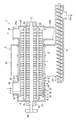
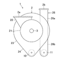
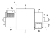
図1は、本発明の実施形態の破砕分別装置を示す縦断面図であり、図2は、破砕分別装置の正面図であり、図3は、破砕分別装置の平面図である。実施形態の破砕分別装置1は、ゴミ処理施設に設置されて都市ゴミの破砕分別処理を行うものである。 FIG. 1 is a longitudinal sectional view showing a crushing and separating apparatus according to an embodiment of the present invention, FIG. 2 is a front view of the crushing and separating apparatus, and FIG. 3 is a plan view of the crushing and separating apparatus. The crushing and separating apparatus 1 according to the embodiment is installed in a garbage disposal facility and performs a crushing and separating process for municipal waste.
この破砕分別装置1は、被処理物が投入される投入口2aと、処理済みの被処理物を排出するは排出口2bとを有するケーシング2内に、投入口2aと排出口2bを概ね結ぶように延在する駆動軸3を備える。駆動軸3の外周面には、両端部に円盤状の端部プレート31,31が固定されており、これら端部プレート31,31の間に複数の円盤状の支持プレート32,32,・・・が固定されている。駆動軸3の外周側には、駆動軸3のまわりに略90°をおいて4つの回転軸4,4,・・・が設けられている。4つの回転軸4,4,・・・は、両端が端部プレート31,31に固定されており、この端部プレート31,31の間の複数の支持プレート31,31,・・・の周縁部を貫通している。各回転軸4,4,・・・には、支持ディスク32,32,・・・の相互間にハンマー5が回動自在に取り付けられている。駆動軸3は、両端がケーシング2の外側に設けられた調心軸受35,35によって支持されている。駆動軸3の一端には、複数のV溝を有するプーリ36が連結されており、このプーリ36に図示しないVベルトが掛け渡され、このVベルトが図示しないモータで駆動されて、駆動軸3を回転駆動するようになっている。
The crushing / separating apparatus 1 generally connects an
上記駆動軸3は、支持ディスク32の縁における周速度が30〜65m/secとなる回転速度で駆動される。ここで、周速度の測定位置は、駆動軸3の中心軸から800〜1000mmの径に相当する位置であり、駆動軸3の回転数は450〜900RPMである。
The
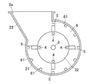
破砕分別装置1のケーシング2内部は、投入口2aが形成された破砕部6と、破砕分別部7と、排出口2bが形成された破砕排出部8とで大略構成されている。図4は、破砕部6の横断面図であり、図5は、破砕分別部7の横断面図であり、図6は、破砕排出部8の横断面図である。
The inside of the
破砕部6は、図4に示すように、ケーシング2の破砕部6に対応する部分である略円筒形状の破砕部ケーシング21内に形成されている。この破砕部ケーシング21の上部には、上端に投入口2aが形成された投入ダクト22が連通して形成されている。破砕部ケーシング21の内側面には、矩形断面を有してケーシングの軸方向に延在する複数の固定刃61,61,・・・が固定されている。
As shown in FIG. 4, the crushing portion 6 is formed in a substantially cylindrical crushing portion casing 21 that is a portion corresponding to the crushing portion 6 of the
破砕部6に配置するハンマー5,5,・・・としては、破砕機能を有する破砕ハンマーと、破砕機能と共に送り機能を有する送りハンマーとを採用できる。
As the
破砕ハンマーとしては、図7Aの正面図に示すような矩形ハンマー51を用いることができる。矩形ハンマー51は、上端部に、回転軸4に挿通されて回転軸4回りに回動自在に支持されるための貫通孔511を有し、この貫通孔511の下側にハンマー本体部512を有する。ハンマー本体部512は、図7Bの底面図からわかるように、矩形断面を有し、図7Aにおいて上下方向に長い直方体形状に形成されている。
As the crushing hammer, a
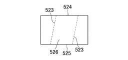
また、破砕部6に配置される破砕ハンマーとしては、図8Aの正面図に示すように、正面視において下端部が幅方向の両側に向かって尖った鉤状ハンマー52を用いることができる。この鉤状ハンマー52は、回転軸4に挿通される貫通孔521と、貫通孔521の下方のハンマー本体部522を有する。ハンマー本体部522は、正面視において、上下方向の中央部にくびれを有する。ハンマー本体部522の対向する側面523,523は、図8Bの底面図に破線で示されるように、幅方向断面が平行四辺形となるように傾斜している。これにより、ハンマー本体部522の側面523と、正面524又は背面525との間に連なる縁が、鋭角に形成されている。正面視において、ハンマー本体部522のくびれた部分の下方の部分は、下端側ほど幅広に形成され、下端の両端部が鋭角に形成されている。これにより、側面523と底面526が連なる縁が鋭角に形成されている。この鉤状ハンマー52が、駆動軸3回りに回転し、また、回転軸4回りに回動することにより、ハンマー本体部522の鋭角の縁が被処理物に食い込んで、金属缶やガラスビン等の硬い被処理物を効果的に破砕するようになっている。
Moreover, as the crushing hammer arranged in the crushing part 6, as shown in the front view of FIG. 8A, a hook-shaped
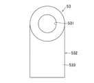
破砕部6に配置される送りハンマーとしては、図9Aの正面図に示すように、ハンマー本体部532が回転軸を法線とする面に対して傾斜した傾斜ハンマー53を用いることができる。この傾斜ハンマー53は、回転軸4に挿通される貫通孔531と、貫通孔531の下方のハンマー本体部532を有する。ハンマー本体部532は、正面視において略矩形に形成され、図9Bの底面図に示すように、正面533と背面534の法線が、回転軸4の中心軸、すなわち、貫通孔531の中心軸に対して傾斜して形成されている。これにより、回転軸4と平行の駆動軸3回りに回転駆動され、また、回転軸4回りに回転したとき、ハンマー本体部532の正面533又は背面534から被処理物に、回転軸4方向へ向かう成分を有する力を作用させることができる。したがって、傾斜ハンマー53は、被処理物を、破砕しつつ回転軸4、すなわち、駆動軸3の延在方向へ送ることができる。
As the feed hammer arranged in the crushing part 6, as shown in the front view of FIG. 9A, an
これらのハンマー51,52,53が設けられた破砕部6では、破砕部ケーシング21の投入ダクト22の投入口2aから投入された被処理物を、矩形ハンマー51、鉤状ハンマー52及び傾斜ハンマー53の打撃作用と、これらハンマー51,52,53と固定刃61,61,・・・とのせん断作用により破砕する。破砕した被処理物を、傾斜ハンマー53の送り作用により、駆動軸3の他端側に連なる破砕分別部7に送るようになっている。
In the crushing unit 6 provided with these
破砕分別部7は、図5の横断面図に示すように、ケーシング2の破砕分別部7に対応する部分である破砕分別部ケーシング23内に、ハンマー5の公転経路の外側に配置された分別手段としてのプレートスクリーン9を収容している。
As shown in the cross-sectional view of FIG. 5, the crushing / separating portion 7 is provided in the crushing / separating portion casing 23 corresponding to the crushing / separating portion 7 of the
破砕分別部ケーシング23は、横断面において上部の略4分の3に相当する部分が円筒形状に形成されている。破砕分別部ケーシング23の円筒形状部分の下側に、ホッパ24が形成されている。ホッパ24は、下方に向かって互いの離隔が狭まる2つの面を有し、下端に排出機構としてのスクリューコンベヤ10を収容している。
The crushing / separating
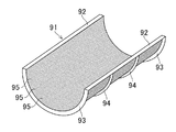
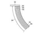
プレートスクリーン9は、図10に示す半円筒スクリーン91を2つ組み合わせて筒状に形成されている。半円筒スクリーン91は、軸方向に延びる2つの直線フレーム92と、直線フレーム92,92の間に掛け渡された両端の円弧フレーム93,93と、直線フレーム92,92の中間に掛け渡された円弧状の中間フレーム94,94を有する。これらのフレームに、複数の板状のスクリーン部材95,95,・・・が支持されている。図11は、半円筒スクリーン91の横断面の端部を拡大して示す図である。図11に示すように、スクリーン部材95,95は、長手方向が半円筒スクリーン91の軸方向に延在し、かつ、短手方向が、半円筒スクリーン91の径方向に延材するように積み重ねられている。スクリーン部材95は、半円筒スクリーン91の径方向の内側から外側に向かって厚みが減少する楔状の断面を有し、厚みの大きい側の端面を、半円筒スクリーン91の内側に臨ませて配列されている。スクリーン部材95は、厚みの大きい側の端面の相互間の隙間を1〜2mmに形成しており、これにより、半円筒スクリーン91の内側に1〜2mmのスリット状の隙間を形成している。スリット状の隙間を1〜2mmに形成することにより、水、食品及び砂等を透過する一方、金属、紙及びプラスチックは透過しないように設定されている。また、スクリーン部材95が、半円筒スクリーン91の径方向の外側に向かうにつれて厚みが小さく形成されていることにより、隣り合うスクリーン部材95の対向する面の間に形成される隙間の大きさが、入口が最も小さい一方、半円筒スクリーン91の径方向の外側に進むにつれて大きくなっている。これにより、半円筒スクリーン91の内側からスクリーン部材95,95の隙間に入った被処理物が、スクリーン部材95,95の隙間を半円筒スクリーン91の径方向の外側に向かって詰まりを生じることなく進行できるようにしている。
The
なお、プレートスクリーン9は、2つの半円筒スクリーン91のうち、下側の半円筒スクリーン91のみを設けてもよい。この場合、上側の半円筒スクリーン91に相当する部分は、ハンマー5の公転経路を取り囲んで被処理物を透過しない壁面等で構成する。あるいは、下側の半円筒スクリーン91の上端と、破砕分別部ケーシング23の内側面との間をシールしてもよい。
The
また、本実施形態では、分別手段としてプレートスクリーン9を用いるが、所定寸法の透過孔を形成した板状体や、所定幅のスリットを形成するように組み合わせた棒状体や、所定寸法の網目を有する網体等を分別手段に用いてもよい。
In the present embodiment, the
破砕分別部7に配置するハンマー5,5,・・・としては、破砕ハンマーと送りハンマーとを採用できる。破砕ハンマーとしては、図7A及び7Bに示す矩形ハンマー51を用いることができ、送りハンマーとしては、図9A及び9Bに示す傾斜ハンマー53を用いることができる。
As the
破砕ハンマーは、図12A及び12Bに示す八角ハンマー54を用いてもよい。八角ハンマー54は、図12Aの正面図に示すように、上端部に、回転軸4に挿通されて回転軸4回りに回動自在に支持されるための貫通孔541を有し、この貫通孔541の下側に、ハンマー本体部542を有する。ハンマー本体部542は、図12Bの底面図からわかるように、幅方向に扁平の八角形断面を有する。この八角ハンマー54は、破砕部6の破砕ハンマーとして用いることも可能である。
As the crushing hammer, an
上記矩形ハンマー51、八角ハンマー54及び傾斜ハンマー53を、駆動軸3回りに回転駆動し、また、回転軸4回りに回動させ、これらのハンマー51,54,53で被処理物を打撃する。ハンマー51,54,53により被処理物に撃力を与えて破砕すると共に、主に矩形ハンマー51及び八角ハンマー54により被処理物に遠心力を与える。遠心力を受けた被処理物は、ハンマー51,54,53の公転軌道の外側に位置するプレートスクリーン9に向かって移動し、スクリーン部材95の相互間の1〜2mmの隙間よりも小さい被処理物が、プレートスクリーン9を透過する。プレートスクリーン9を透過する被処理物は、水や油等の流動体や、食品等の柔軟な固形物や、砂等の寸法の小さい固形物である。プレートスクリーン9を通過した被処理物を、プレートスクリーン9と破砕分別部ケーシング23の内側面との間を移動させてホッパ24に収集し、スクリューコンベヤ10によってケーシング2外に排出するようになっている。
The
プレートスクリーン9を透過しないでプレートスクリーン9内に残留した被処理物は、傾斜ハンマー53の送り作用により、駆動軸3の他端側に連なる破砕排出部8に送るようになっている。プレートスクリーン9内に残留して破砕排出部8に送る被処理物は、例えば金属、紙及びプラスチック等であり、これらは、プレートスクリーン9で水が分離されることにより、脱水状態となる。
The object to be processed that does not pass through the
破砕排出部8は、図6に示すように、ケーシング2の破砕排出部8に対応する部分である破砕排出部ケーシング25と、破砕排出部ケーシング25の側部に設けられたダクト26を備える。破砕排出部ケーシング25は、ハンマー5の公転経路の外側を取り囲むように、概ね円筒形状を有する。破砕排出部ケーシング25の内部とダクト26の内部は互いに連通しており、横断面において、破砕排出部ケーシング25の接線がダクト26の中心線に概ね重なるように形成されている。ダクト26の破砕排出部ケーシング25との接続部よりも上側の部分は上部ダクト26aであり、この上部ダクト26aの上端には排出口2bが形成されている。ダクト26の破砕排出部ケーシング25との接続部よりも下側の部分は下部ダクト26bであり、この下部ダクト26bの下端は、スクリューコンベヤ11に連結されている。
As shown in FIG. 6, the crushing / discharging
破砕排出部8に配置するハンマー5,5,・・・としては、図13A及び13Bに示すような送風ハンマー55を用いることができる。送風ハンマー55は、図13Aの正面図に示すように、上端部に、回転軸4に挿通されて回転軸4回りに回動自在に支持されるための貫通孔551を有し、この貫通孔551の下側にハンマー本体部552を有する。ハンマー本体部552は、図13Bの底面図からわかるように、貫通孔551の中心軸と略並行に形成されている。送風ハンマー55は、駆動軸3回りに回転駆動され、また、回転軸4回りに回動することにより、破砕分別部7から導かれた被処理物を打撃して破砕するようになっている。また、送風ハンマー55は、貫通孔551、すなわち、回転軸4と平行なハンマー本体部552により、破砕排出部ケーシング25内に、駆動軸3回りの空気の回転流れを形成する。さらに、送風ハンマー55のハンマー本体552は、被処理物に、送風ハンマー55の公転経路の接線方向を概ね向いた力を作用させる。このように、送風ハンマー55の本体部552は、破砕及び風生成面として機能する。
As the
送風ハンマー55で生成した駆動軸3回りの風は、破砕排出部ケーシング25から上部ダクト26aに流入して上部ダクト26aを上方に向かって流れる。比重が比較的小さい被処理物を、送風ハンマー55で生成した風で破砕排出部ケーシング25から上部ダクト26aに導いて、排出口2bから排出する。排出口2bから排出される被処理物の多くは、紙及びプラスチックであり、排出口2bに接続した図示しないフィルタ装置で収集して再生資源として利用する。
The wind around the
下部ダクト26bでは、送風ハンマー55で生成された風では搬送されない被処理物が、送風ハンマー55から受けた公転経路の接線方向の力により、破砕排出部ケーシング25から導かれて落下する。下部ダクト26bを落下する被処理物は、比重が比較的大きい金属やガラス等である。下部ダクト26bを落下した被処理物は、下端のスクリューコンベヤ11で収集される。
In the
スクリューコンベヤ10は、破砕分別部7で分別収集された水、食品及び砂等を搬送し、排出口10aから排出する。また、スクリューコンベヤ11は、破砕排出部8で分別収集された金属等を搬送し、図示しない排出口から排出する。スクリューコンベヤ10で搬送された水、食品及び砂等には乾燥処理を施す一方、スクリューコンベヤ11で搬送された金属等には再生処理を施すことにより、分別収集した材料を効率的かつ有効に処理することができる。
The
本実施形態の破砕分別装置1によれば、破砕分別部7において、水平方向を向く駆動軸3で駆動されるハンマー5の遠心力により、水がプレートスクリーン9を透過して、プレートスクリーン9を透過しない被処理物と分離する。プレートスクリーン9を透過した水は、破砕分別部ケーシング23の下方のホッパ24で収集してスクリューコンベヤ10で排出する。したがって、被処理物に含まれる水及び油等の流動物は、駆動軸3等を伝わることなく効果的に収集されて排出されるので、従来のように、水や油が鉛直向きの駆動軸を伝って可動部品に浸入する不都合を防止できる。したがって、この破砕分別装置1は、水や油等の流動物を含む生ゴミ等を含んだ被処理物を安定して処理でき、しかも、故障が少なく、メンテナンスや修理の手間を削減できる。
According to the crushing / separating apparatus 1 of this embodiment, in the crushing / separating unit 7, water permeates the
また、本実施形態の破砕分別装置1によれば、軽量の被処理物を、破砕分別部7で脱水した後に、破砕排出部8の送風ハンマー55で生成された風で排出するので、上部ダクト26aの内側面や、排出口2bに接続される搬送用のダクトの内側面に付着することなく、軽量の被処理物を風によって効率的に排出することができる。したがって、従来のように、水を含んだ被処理物がダクトや収集容器に付着する不都合を防止できる。また、被処理物を、破砕分別部7においてプレートスクリーン9で分別し、また、脱水した後、風の力で排出口2bから排出するので、排出する被処理物の大きさや比重のばらつきを少なくできる。
Moreover, according to the crushing and separating apparatus 1 of the present embodiment, the light-weight object to be processed is dehydrated by the crushing and separating unit 7 and then discharged by the wind generated by the
また、破砕部6、破砕分別部7及び破砕排出部8において、ハンマー5で被処理物を破砕するので、被処理物に金属等が含まれていても、容易に破砕して分別することができる。したがって、この破砕分別装置1から排出された被処理物は、再生資源として有効に利用することができる。
Moreover, in the crushing part 6, the crushing and separating part 7 and the crushing and discharging
また、本実施形態の破砕分別装置1によれば、1つの装置で破砕、選別及び脱水を行うことができるので、従来よりも、選別装置や脱水装置を削減できる。したがって、被処理物の処理施設の省スペースができると共に、設備コストを削減することができる。 Moreover, according to the crushing and separating apparatus 1 of the present embodiment, the crushing, sorting and dewatering can be performed with one apparatus, so that the sorting apparatus and the dewatering apparatus can be reduced as compared with the prior art. Therefore, it is possible to save the space of the processing facility for the object to be processed and reduce the equipment cost.
本実施形態の破砕分別装置1は、水分を比較的多く含む被処理物や、金属製の比較的大型の被処理物を安定して処理できる。したがって、生ゴミを多く含む都市ゴミ等の一般廃棄物のほか、例えば食品加工工場から排出される食品残渣や、農水産業の廃棄物等のような高水分の廃棄物を、効果的に破砕及び分別することができる。また、例えば水や油を収容した金属缶等のように、比較的多くの流動体を含むと共に金属製の部材を有する被処理物を、効果的に破砕及び分別することができる。また、例えば農業用のプラスチック製の廃棄物のように、土砂や堆肥等が付着した廃棄物を、水分と共に破砕分別装置に投入することにより、破砕分別部で土砂等の付着物を効果的に分離して破砕することができる。 The crushing and separating apparatus 1 of the present embodiment can stably process an object to be processed that contains a relatively large amount of water or a metal object that is relatively large. Therefore, in addition to general waste such as municipal waste that contains a lot of raw garbage, high-moisture waste such as food residues discharged from food processing factories and agricultural and fishery wastes can be effectively crushed and Can be separated. In addition, for example, a processing object including a relatively large amount of fluid and having a metal member, such as a metal can containing water or oil, can be effectively crushed and separated. Also, for example, by putting waste with soil and compost attached to the crushing / separating device together with moisture, such as plastic waste for agriculture, the crushing / separating part effectively removes the deposits such as earth and sand. It can be separated and crushed.
また、本発明の破砕分別装置は、廃石膏ボードの破砕分別処理に好適である。最近、建築廃材として排出される廃石膏ボードを再生処理して石膏成分を抽出し、リサイクル資源として活用することが試行されている。廃石膏ボードには、石膏と共に紙等の可燃成分が用いられているが、リサイクル資源として実用に耐える品質の石膏を得るには、廃石膏ボードの紙成分を高精度に除去する必要がある。また、石膏がリサイクル資源として再利用されず、最終処分に付された場合も考慮し、硫化水素の発生防止の観点や熱しゃく減量の低下の観点から、石膏に残留する紙等の可燃成分を、所定の割合以下とする必要がある。このように、廃石膏ボードの処理では、石膏と可燃成分を高度に分別する必要がある。 Moreover, the crushing and sorting apparatus of the present invention is suitable for crushing and sorting processing of waste gypsum board. Recently, attempts have been made to recycle waste gypsum board discharged as building waste material, extract gypsum components, and use them as recycling resources. The waste gypsum board uses combustible components such as paper together with gypsum. However, in order to obtain a gypsum that can be used practically as a recycled resource, it is necessary to remove the paper components of the waste gypsum board with high accuracy. In consideration of cases where gypsum is not reused as a recycling resource and is subject to final disposal, combustible components such as paper remaining on the gypsum should be removed from the viewpoint of preventing hydrogen sulfide generation and reducing heat loss. , It is necessary to set it to a predetermined ratio or less. Thus, in the treatment of waste gypsum board, it is necessary to highly separate gypsum and combustible components.
従来、廃石膏ボードの再生処理では、破砕装置で廃石膏ボードを破砕した後、分別装置で石膏と可燃成分を分別していた。しかしながら、廃石膏ボードは、建築廃材として排出された状態で多量の水分を含んでいることが多く、従来の破砕装置では、水分で粘着性を帯びた石膏が破砕刃に付着して、破砕効率の悪化や、破砕装置の異常停止を招く問題がある。また、廃石膏ボードを破砕した後、石膏と可燃成分を分別する前に、乾燥を行う必要がある。石膏と可燃成分を含んだ破砕片を乾燥させるには、可燃成分の引火を防止する必要があるため、手間を要する問題がある。 Conventionally, in the recycling treatment of waste gypsum board, after the waste gypsum board is crushed with a crushing device, gypsum and combustible components are separated with a sorting device. However, waste gypsum board often contains a large amount of moisture in the state of being discharged as building waste, and with conventional crushing devices, gypsum sticky with moisture adheres to the crushing blade, and crushing efficiency There is a problem of causing deterioration of the crushing device and abnormal stopping of the crushing device. Moreover, after crushing a waste gypsum board, it is necessary to dry before fractionating gypsum and a combustible component. In order to dry the crushed piece containing gypsum and the combustible component, it is necessary to prevent the combustible component from being ignited.
ここで、本発明の実施形態の破砕分別装置1を廃石膏ボードの破砕分別処理に用いることにより、水分を含んだ廃石膏ボードであっても、精度良く石膏と可燃成分とに分別することができる。例えば、廃石膏ボードに粗破砕を行って15cm角程度の大きさとし、この粗破砕片を投入口2aに投入する。投入された廃石膏ボードの粗破砕片は、破砕部6で矩形ハンマー51や八角ハンマー54で破砕された後、傾斜ハンマー53で破砕分別部7へ送られる。破砕分別部7では、矩形ハンマー51や八角ハンマー54で更に破砕されて遠心力を受け、プレートスクリーン9を、水分を含んだ石膏成分が透過する。プレートスクリーン9を透過した石膏成分は、ホッパ24を通ってスクリューコンベヤ10で排出される。プレートスクリーン9の内側に残留した紙等の可燃成分は、傾斜ハンマー53で破砕排出部8へ送られる。破砕排出部8では、送風ハンマー55で破砕され、送風ハンマー55で生成された風の力によって上部ダクト26aを通って排出される。また、廃石膏ボードの固定金具等の重量物は、下部ダクト26bを通してスクリューコンベヤ11によって排出される。
Here, by using the crushing and separating apparatus 1 of the embodiment of the present invention for the crushing and separating processing of the waste gypsum board, even waste waste gypsum board containing moisture can be accurately separated into gypsum and combustible components. it can. For example, the waste gypsum board is roughly crushed to a size of about 15 cm square, and this coarsely crushed piece is put into the
このように、破砕分別部7のプレートスクリーン9で、石膏と可燃成分とを精度よく分別することができる。また、破砕分別部7で、紙等の可燃成分から水分を分離するので、破砕排出部8を通って排出口2aから排出された可燃成分は、引火を防止しながら乾燥させる必要が無い。したがって、可燃成分の取り扱いの容易化を図ることができる。なお、排出口2aに、バグフィルタ等のフィルタ装置を接続することにより、石膏成分の粉塵の飛散を防止することができる。
Thus, the plaster and the combustible component can be accurately separated by the
また、破砕分別部7のプレートスクリーン9で分別した石膏成分は、水分を含有するが、スクリューコンベヤ10によって効率的に排出することができる。また、プレートスクリーン9で分別した石膏成分は、殆ど可燃成分を含まないので、引火防止対策が不要であり、したがって、効率的に乾燥させることができる。
Further, the gypsum component separated by the
1 破砕分別装置
2 ケーシング
2a 投入口
2b 排出口
3 駆動軸
4 回転軸
5 ハンマー
6 破砕部
7 破砕分別部
8 破砕排出部
DESCRIPTION OF SYMBOLS 1 Crushing and separating
Claims (9)
上記破砕部は、上記投入口から投入された被処理物を、上記ハンマーで破砕すると共に破砕分別部に送るように形成され、
上記破砕分別部は、上記ハンマーの公転経路の外側に配置されて透過隙間を有する分別手段を備え、上記破砕部から送られた被処理物を、上記ハンマーで破砕すると共に遠心力を与えて上記分別手段を通過させる一方、上記分別手段を透過しない被処理物を破砕排出部に送るように形成され、
上記破砕排出部は、上記破砕分別部から送られた被処理物を、上記ハンマーで破砕すると共に、上記ハンマーで生成した風と遠心力により、破砕した被処理物を排出口から排出するように形成されていることを特徴とする破砕分別装置。 In a horizontally long casing having a workpiece inlet on one end side and a workpiece outlet on the other end side, a drive shaft arranged substantially horizontally and revolving around the drive shaft A crushing / separating apparatus comprising a plurality of hammers provided to be rotatable, wherein a casing is divided into a crushing part, a crushing / separating part, and a crushing / discharging part in order from the inlet to the outlet. ,
The crushing part is formed so as to crush the object to be processed introduced from the charging port with the hammer and send it to the crushing and separating part.
The crushing / separating unit includes a separating unit disposed outside the revolution path of the hammer and having a permeation gap, and crushes the object to be processed sent from the crushing unit with the hammer and applies a centrifugal force to the processing unit. While passing through the separation means, it is formed so as to send an object to be processed that does not pass through the separation means to the crushing discharge part,
The crushing and discharging unit crushes the object to be processed sent from the crushing and separating unit with the hammer, and discharges the crushed object to be processed from the discharge port by wind and centrifugal force generated by the hammer. A crushing and separating apparatus characterized by being formed.
上記破砕部の少なくとも1つのハンマーが、被処理物を駆動軸の延在方向に送るように形成されていることを特徴とする破砕分別装置。 In the crushing and separating apparatus according to claim 1,
The crushing and separating apparatus, wherein at least one hammer of the crushing part is formed so as to send an object to be processed in the extending direction of the drive shaft.
上記破砕部の少なくとも1つのハンマーが、先端部が鉤状に形成されていることを特徴とする破砕分別装置。 In the crushing and separating apparatus according to claim 1,
The crushing and separating apparatus, wherein at least one hammer of the crushing part is formed in a bowl shape at a tip part.
上記破砕分別部の少なくとも1つのハンマーが、被処理物を駆動軸の延在方向に送るように形成されていることを特徴とする破砕分別装置。 In the crushing and separating apparatus according to claim 1,
A crushing / separating apparatus, wherein at least one hammer of the crushing / separating unit is formed so as to send an object to be processed in an extending direction of a drive shaft.
上記破砕排出部の少なくとも1つのハンマーが、上記駆動軸と略平行に延在する風生成面を有することを特徴とする破砕分別装置。 In the crushing and separating apparatus according to claim 1,
The crushing and separating apparatus, wherein at least one hammer of the crushing discharge section has a wind generating surface extending substantially parallel to the drive shaft.
上記破砕分別部に、上記分別手段の透過隙間を透過した被処理物を収集するホッパと、このホッパで収集された被処理物をケーシング外に排出する排出機構が設けられていることを特徴とする破砕分別装置。 In the crushing and separating apparatus according to claim 1,
The crushing / separating section is provided with a hopper that collects the workpiece that has passed through the permeation gap of the sorting means, and a discharge mechanism that discharges the workpiece collected by the hopper to the outside of the casing. Crushing and separating device.
上記破砕排出部に、分別手段を透過した被処理物を下方に導くダクトと、このダクトで導かれた被処理物をケーシング外に排出する排出機構が設けられていることを特徴とする破砕分別装置。 In the crushing and separating apparatus according to claim 1,
In the crushing and discharging unit, a crushing and separating unit is provided with a duct that guides the object to be processed that has passed through the separating means downward, and a discharge mechanism that discharges the object to be processed guided by the duct to the outside of the casing. apparatus.
上記排出機構が、スクリューコンベヤで形成されていることを特徴とする破砕分別装置。 In the crushing and separating apparatus according to claim 6 or 7,
The crushing and separating apparatus, wherein the discharge mechanism is formed by a screw conveyor.
上記破砕分別部の分別手段が、上記ハンマーの先端の公転経路の少なくとも一部を取り囲むように上記駆動軸の径方向に延在して配置された複数の板状体を有し、これら板状体の相互間に形成されたスリット状の隙間によって上記透過隙間が形成されていることを特徴とする破砕分別装置。 In the crushing and separating apparatus according to claim 1,
The separation means of the crushing and separating unit has a plurality of plate-like bodies arranged extending in the radial direction of the drive shaft so as to surround at least a part of the revolution path of the tip of the hammer, The crushing and separating apparatus, wherein the permeation gap is formed by a slit-like gap formed between the bodies.
Priority Applications (1)
| Application Number | Priority Date | Filing Date | Title |
|---|---|---|---|
| JP2010255850A JP5686579B2 (en) | 2010-11-16 | 2010-11-16 | Crushing and separating apparatus and crushing and separating method |
Applications Claiming Priority (1)
| Application Number | Priority Date | Filing Date | Title |
|---|---|---|---|
| JP2010255850A JP5686579B2 (en) | 2010-11-16 | 2010-11-16 | Crushing and separating apparatus and crushing and separating method |
Publications (2)
| Publication Number | Publication Date |
|---|---|
| JP2012106162A true JP2012106162A (en) | 2012-06-07 |
| JP5686579B2 JP5686579B2 (en) | 2015-03-18 |
Family
ID=46492400
Family Applications (1)
| Application Number | Title | Priority Date | Filing Date |
|---|---|---|---|
| JP2010255850A Active JP5686579B2 (en) | 2010-11-16 | 2010-11-16 | Crushing and separating apparatus and crushing and separating method |
Country Status (1)
| Country | Link |
|---|---|
| JP (1) | JP5686579B2 (en) |
Cited By (6)
| Publication number | Priority date | Publication date | Assignee | Title |
|---|---|---|---|---|
| CN102962242A (en) * | 2012-12-04 | 2013-03-13 | 汨罗万容电子废弃物处理有限公司 | Harmless treatment and resource recovery method and harmless treatment and resource recovery equipment for waste circuit board with components |
| JP2016131956A (en) * | 2015-01-22 | 2016-07-25 | 株式会社大貴 | Separation unit and manufacturing method for water absorption treatment material |
| KR101825266B1 (en) * | 2014-06-19 | 2018-03-22 | 대보건설 주식회사 | Hacking dry-cutter equipment for combustible waste |
| CN110201750A (en) * | 2019-07-06 | 2019-09-06 | 枣庄鑫金山智能机械股份有限公司 | A kind of automatic material clearing hammer type sand production machine |
| CN113731782A (en) * | 2021-09-16 | 2021-12-03 | 侯芳 | Graded sand screening treatment device and method for water conservancy municipal engineering |
| CN114160265A (en) * | 2021-12-03 | 2022-03-11 | 萍乡市旭华电瓷电器制造有限公司 | Soil mud screening mechanism for porcelain insulator production |
Citations (6)
| Publication number | Priority date | Publication date | Assignee | Title |
|---|---|---|---|---|
| JPS62103437U (en) * | 1985-12-20 | 1987-07-01 | ||
| JP3018367U (en) * | 1995-05-20 | 1995-11-21 | 和雄 平川 | Waste shredder |
| JP2008036577A (en) * | 2006-08-09 | 2008-02-21 | Miike Iron Works Co Ltd | Garbage crusher |
| JP3139608U (en) * | 2007-12-07 | 2008-02-21 | シキボウ株式会社 | Defibrating equipment |
| JP2010082559A (en) * | 2008-09-30 | 2010-04-15 | Tajiri:Kk | Apparatus for sorting garbage |
| JP2010234222A (en) * | 2009-03-31 | 2010-10-21 | Hitachi Zosen Corp | Waste disposal facility |
-
2010
- 2010-11-16 JP JP2010255850A patent/JP5686579B2/en active Active
Patent Citations (6)
| Publication number | Priority date | Publication date | Assignee | Title |
|---|---|---|---|---|
| JPS62103437U (en) * | 1985-12-20 | 1987-07-01 | ||
| JP3018367U (en) * | 1995-05-20 | 1995-11-21 | 和雄 平川 | Waste shredder |
| JP2008036577A (en) * | 2006-08-09 | 2008-02-21 | Miike Iron Works Co Ltd | Garbage crusher |
| JP3139608U (en) * | 2007-12-07 | 2008-02-21 | シキボウ株式会社 | Defibrating equipment |
| JP2010082559A (en) * | 2008-09-30 | 2010-04-15 | Tajiri:Kk | Apparatus for sorting garbage |
| JP2010234222A (en) * | 2009-03-31 | 2010-10-21 | Hitachi Zosen Corp | Waste disposal facility |
Cited By (8)
| Publication number | Priority date | Publication date | Assignee | Title |
|---|---|---|---|---|
| CN102962242A (en) * | 2012-12-04 | 2013-03-13 | 汨罗万容电子废弃物处理有限公司 | Harmless treatment and resource recovery method and harmless treatment and resource recovery equipment for waste circuit board with components |
| KR101825266B1 (en) * | 2014-06-19 | 2018-03-22 | 대보건설 주식회사 | Hacking dry-cutter equipment for combustible waste |
| JP2016131956A (en) * | 2015-01-22 | 2016-07-25 | 株式会社大貴 | Separation unit and manufacturing method for water absorption treatment material |
| WO2016117145A1 (en) * | 2015-01-22 | 2016-07-28 | 株式会社大貴 | Separating apparatus and method for manufacturing water absorption material |
| US10124371B2 (en) | 2015-01-22 | 2018-11-13 | Daiki Co., Ltd. | Separation device and method for manufacturing water absorption material |
| CN110201750A (en) * | 2019-07-06 | 2019-09-06 | 枣庄鑫金山智能机械股份有限公司 | A kind of automatic material clearing hammer type sand production machine |
| CN113731782A (en) * | 2021-09-16 | 2021-12-03 | 侯芳 | Graded sand screening treatment device and method for water conservancy municipal engineering |
| CN114160265A (en) * | 2021-12-03 | 2022-03-11 | 萍乡市旭华电瓷电器制造有限公司 | Soil mud screening mechanism for porcelain insulator production |
Also Published As
| Publication number | Publication date |
|---|---|
| JP5686579B2 (en) | 2015-03-18 |
Similar Documents
| Publication | Publication Date | Title |
|---|---|---|
| JP5686579B2 (en) | Crushing and separating apparatus and crushing and separating method | |
| RU2596129C2 (en) | Device and method for processing garbage packed into bags | |
| US11180391B2 (en) | Method and device for processing solid waste | |
| JP6511168B2 (en) | Separator for separating paper and plastic film from paper container | |
| CA3001749C (en) | Method and device for processing solid waste | |
| JP4585494B2 (en) | Crusher with wind sorter | |
| JP2010029829A (en) | Cleaning and sorting apparatus for kitchen garbage bag | |
| JP5670707B2 (en) | Waste crushing and sorting equipment | |
| KR20140134829A (en) | Combustible foreign matter dry blow screening device | |
| KR20170012764A (en) | Garbage crushing and sorting apparatus of organic waste | |
| US20150306631A1 (en) | Waste sorting device having a rotary screen | |
| TWM546265U (en) | Continuous dewatering de-oiling centrifugal machine | |
| WO2017173983A1 (en) | Bale breaking and dust removing device | |
| KR101546356B1 (en) | Hit wind type sorting apparatus for waste | |
| EP0893220B1 (en) | Apparatus for recycling polyethylene, particularly polyethylene foil | |
| KR101638182B1 (en) | Waste film recycling system | |
| KR101341277B1 (en) | Drying device for waste vinyl | |
| JP2008030364A (en) | Washing apparatus for sheet made of synthetic resin | |
| JP6143719B2 (en) | Waste sorting machine | |
| JP7418783B2 (en) | Separation device | |
| WO2017173985A1 (en) | Dust dry removal apparatus | |
| EP3960298A1 (en) | Machine for triturating and separating biodegradable material from non-biodegradable material and installation comprising said machine | |
| JP5127761B2 (en) | Waste treatment facility | |
| KR100904303B1 (en) | A wet sorting method for waste plastics using specific gravity difference | |
| JP2002138379A (en) | Washing dehydrator for small piece of recovered paper cup, milk carton, or the like, and recycling treatment apparatus |
Legal Events
| Date | Code | Title | Description |
|---|---|---|---|
| A621 | Written request for application examination |
Free format text: JAPANESE INTERMEDIATE CODE: A621 Effective date: 20130730 |
|
| A977 | Report on retrieval |
Free format text: JAPANESE INTERMEDIATE CODE: A971007 Effective date: 20140417 |
|
| A131 | Notification of reasons for refusal |
Free format text: JAPANESE INTERMEDIATE CODE: A131 Effective date: 20140603 |
|
| A521 | Written amendment |
Free format text: JAPANESE INTERMEDIATE CODE: A523 Effective date: 20140804 |
|
| TRDD | Decision of grant or rejection written | ||
| A01 | Written decision to grant a patent or to grant a registration (utility model) |
Free format text: JAPANESE INTERMEDIATE CODE: A01 Effective date: 20150120 |
|
| A61 | First payment of annual fees (during grant procedure) |
Free format text: JAPANESE INTERMEDIATE CODE: A61 Effective date: 20150120 |
|
| R150 | Certificate of patent or registration of utility model |
Ref document number: 5686579 Country of ref document: JP Free format text: JAPANESE INTERMEDIATE CODE: R150 |
|
| R250 | Receipt of annual fees |
Free format text: JAPANESE INTERMEDIATE CODE: R250 |
|
| R250 | Receipt of annual fees |
Free format text: JAPANESE INTERMEDIATE CODE: R250 |