JP2012003197A - Microscope device and image acquisition method - Google Patents
Microscope device and image acquisition method Download PDFInfo
- Publication number
- JP2012003197A JP2012003197A JP2010140790A JP2010140790A JP2012003197A JP 2012003197 A JP2012003197 A JP 2012003197A JP 2010140790 A JP2010140790 A JP 2010140790A JP 2010140790 A JP2010140790 A JP 2010140790A JP 2012003197 A JP2012003197 A JP 2012003197A
- Authority
- JP
- Japan
- Prior art keywords
- sample
- image
- micro
- block
- macro
- Prior art date
- Legal status (The legal status is an assumption and is not a legal conclusion. Google has not performed a legal analysis and makes no representation as to the accuracy of the status listed.)
- Granted
Links
- 238000000034 method Methods 0.000 title claims description 15
- 239000011521 glass Substances 0.000 claims abstract description 28
- 238000003384 imaging method Methods 0.000 claims abstract description 24
- 238000000605 extraction Methods 0.000 claims abstract description 19
- 238000004040 coloring Methods 0.000 claims description 2
- 230000003287 optical effect Effects 0.000 description 12
- 230000005484 gravity Effects 0.000 description 4
- 239000003550 marker Substances 0.000 description 2
- 238000010586 diagram Methods 0.000 description 1
- 239000000284 extract Substances 0.000 description 1
- 230000004048 modification Effects 0.000 description 1
- 238000012986 modification Methods 0.000 description 1
- 238000005070 sampling Methods 0.000 description 1
Images


Classifications
-
- H—ELECTRICITY
- H04—ELECTRIC COMMUNICATION TECHNIQUE
- H04N—PICTORIAL COMMUNICATION, e.g. TELEVISION
- H04N7/00—Television systems
- H04N7/18—Closed-circuit television [CCTV] systems, i.e. systems in which the video signal is not broadcast
- H04N7/183—Closed-circuit television [CCTV] systems, i.e. systems in which the video signal is not broadcast for receiving images from a single remote source
-
- G—PHYSICS
- G02—OPTICS
- G02B—OPTICAL ELEMENTS, SYSTEMS OR APPARATUS
- G02B21/00—Microscopes
- G02B21/24—Base structure
- G02B21/241—Devices for focusing
-
- G—PHYSICS
- G02—OPTICS
- G02B—OPTICAL ELEMENTS, SYSTEMS OR APPARATUS
- G02B21/00—Microscopes
- G02B21/36—Microscopes arranged for photographic purposes or projection purposes or digital imaging or video purposes including associated control and data processing arrangements
- G02B21/365—Control or image processing arrangements for digital or video microscopes
- G02B21/367—Control or image processing arrangements for digital or video microscopes providing an output produced by processing a plurality of individual source images, e.g. image tiling, montage, composite images, depth sectioning, image comparison
Abstract
Description
本発明は、顕微鏡装置および画像取得方法に関するものである。 The present invention relates to a microscope apparatus and an image acquisition method.
従来、スライドガラス上の試料のマクロ画像を取得して、該マクロ画像内の試料の領域を抽出し、この領域を複数の小領域に分割して、各小領域に対応する高解像度のミクロ画像を取得する顕微鏡が知られている(例えば、特許文献1参照。)。取得された複数のミクロ画像をつなぎ合わせることにより、試料全体を高解像度で観察可能ないわゆるバーチャルスライドを構築することができる。 Conventionally, a macro image of a sample on a slide glass is acquired, a region of the sample in the macro image is extracted, this region is divided into a plurality of small regions, and a high-resolution micro image corresponding to each small region There is known a microscope that acquires the above (see, for example, Patent Document 1). A so-called virtual slide capable of observing the entire sample with high resolution can be constructed by connecting a plurality of acquired micro images.
しかしながら、スライドガラス上の試料にオートフォーカスによって合焦位置を追従させながらミクロ画像を取得する場合には、オートフォーカスの失敗を回避するために、オートフォーカス範囲を一定の範囲に限定し、この範囲を超える場合には、オートフォーカス動作を停止することが行われる。 However, when acquiring a micro image while following the in-focus position by autofocusing on the sample on the slide glass, the autofocus range is limited to a certain range in order to avoid autofocus failure. If it exceeds, auto-focus operation is stopped.
すなわち、試料がスライドガラス上に連続的に存在している場合には、オートフォーカス範囲内において合焦位置が小刻みに変化するので、常に合焦状態を維持することができる。しかしながら、スライドガラスに搭載される試料は、スライドガラス上に点在して複数の島を構成して配置される場合があり、スライドガラスの厚さの変動等により、各島の試料にオートフォーカス範囲を超える高低差が発生している場合には、ミクロ画像の取得領域が一の島からの他の島へ移行する際に、オートフォーカスに失敗して、合焦が得られず、不鮮明なミクロ画像が取得されてしまうという不都合がある。 That is, when the sample is continuously present on the slide glass, the in-focus state can be always maintained because the in-focus position changes in small increments within the autofocus range. However, the sample mounted on the slide glass may be arranged in a plurality of islands scattered on the slide glass, and auto focus on each island sample due to the variation of the slide glass thickness, etc. When the height difference exceeding the range has occurred, when the micro image acquisition area shifts from one island to another, autofocusing fails, focusing is not obtained, and the micro image is unclear. Has the disadvantage of being acquired.
本発明は上述した事情に鑑みてなされたものであって、スライドガラス上に試料が点在する場合においても、すべての試料において鮮明なミクロ画像を取得して、空間分解能の高いバーチャルスライドを構築することができる顕微鏡装置および画像取得方法を提供することを目的としている。 The present invention has been made in view of the above-described circumstances, and even when samples are scattered on a slide glass, a clear micro image is obtained for all samples to construct a virtual slide with high spatial resolution. It is an object of the present invention to provide a microscope apparatus and an image acquisition method that can be used.
上記目的を達成するために、本発明は以下の手段を提供する。
本発明は、試料を搭載したスライドガラスのマクロ画像を取得するマクロ撮像部と、該マクロ撮像部により取得されたスライドガラスのマクロ画像において、試料を抽出する抽出部と、該抽出部により抽出された試料が複数点在している場合に、各試料の塊を含む複数のブロックを定義するブロック設定部と、該ブロック設定部により定義されたブロック内において、試料を含む領域を複数の小領域に分割する領域分割部と、該領域分割部により生成された各小領域について、該小領域内の試料に対しオートフォーカス動作を行いながら前記マクロ画像よりも解像度の高いミクロ画像を取得するミクロ撮像部とを備え、該ミクロ撮像部が、前記ブロック設定部により設定されたブロック毎に、オートフォーカスの合焦位置を探索する顕微鏡装置を提供する。
In order to achieve the above object, the present invention provides the following means.
The present invention provides a macro imaging unit that acquires a macro image of a slide glass on which a sample is mounted, an extraction unit that extracts a sample in the macro image of the slide glass acquired by the macro imaging unit, and the extraction unit that is extracted by the extraction unit. When a plurality of samples are scattered, a block setting unit for defining a plurality of blocks including a lump of each sample, and a region including the sample in a block defined by the block setting unit Micro-imaging that obtains a micro image having a higher resolution than the macro image while performing an autofocus operation on a sample in the small region for each of the small regions generated by the region dividing unit A microscope device for searching for a focus position of autofocus for each block set by the block setting unit. To provide.
本発明によれば、マクロ撮像部により取得されたスライドガラスのマクロ画像から、抽出部により試料が抽出され、試料が複数点在している場合には、ブロック設定部により複数のブロックが定義される。そして、各ブロックにおいて領域分割部により試料を含む領域が複数の小領域に分割され、ミクロ撮像部において各小領域のミクロ画像が取得される。この場合において、ミクロ撮像部によるミクロ画像の取得に先立って、ブロック毎にオートフォーカスの合焦位置の探索が行われ、その後、各小領域内の試料に対しオートフォーカス動作を行いながらミクロ画像が取得される。これにより、異なるブロックの試料間に大きな高低差が発生していたとしても、オートフォーカスを失敗することなく、試料の鮮明なミクロ画像を取得することができる。 According to the present invention, the sample is extracted by the extraction unit from the macro image of the slide glass acquired by the macro imaging unit, and when a plurality of samples are scattered, the block setting unit defines a plurality of blocks. The In each block, the region including the sample is divided into a plurality of small regions by the region dividing unit, and a micro image of each small region is acquired in the micro imaging unit. In this case, prior to the acquisition of the micro image by the micro imaging unit, the focus position of the auto focus is searched for each block, and then the micro image is obtained while performing the auto focus operation on the sample in each small region. To be acquired. Thereby, even if a large height difference occurs between samples in different blocks, a clear micro image of the sample can be acquired without failing the autofocus.
上記発明においては、前記ミクロ撮像部は、前記ブロック毎の合焦位置の探索において合焦位置が発見できなかったブロックにおけるミクロ画像の取得を行わないこととしてもよい。
合焦位置の探索によっても合焦位置が発見できない場合は、例えば、スライドガラスの表面に油性インクでかかれた文字のようにコントラスト差のないものである場合があり、そのような場合にまで、ミクロ画像が取得されてしまう不都合の発生を防止することができる。
In the above invention, the micro imaging unit may not acquire a micro image in a block in which a focus position cannot be found in a search for a focus position for each block.
If the in-focus position cannot be found by searching for the in-focus position, for example, the surface of the slide glass may have no contrast difference, such as characters written with oil-based ink. It is possible to prevent the occurrence of inconvenience that a micro image is acquired.
また、上記発明においては、前記ミクロ撮像部による前記ブロック毎の合焦位置の探索の結果、合焦位置が発見できなかったブロックに、前記マクロ画像上において標識を付与する画像処理部を備えていてもよい。
このようにすることで、合焦位置が発見できず、ミクロ画像の取得が行われなかったブロックは、マクロ画像上において付与される標識により、事後的にその旨を確認することができる。
In the above invention, the image processing unit for adding a marker on the macro image to a block in which the in-focus position cannot be found as a result of the in-focus position search for each block by the micro imaging unit is provided. May be.
By doing in this way, the fact that the in-focus position cannot be found and the block for which the micro image has not been acquired can be confirmed afterwards by the label attached on the macro image.
また、上記発明においては、前記画像処理部は、合焦位置が発見できなかったブロックに着色することにより標識を付与してもよい。
このようにすることで、合焦位置が発見できず、ミクロ画像の取得が行われなかったブロックを、視覚的により容易に確認することができる。
Moreover, in the said invention, the said image process part may provide a label | marker by coloring the block in which the focus position was not found.
By doing so, it is possible to more easily visually confirm the block in which the in-focus position cannot be found and the micro image has not been acquired.
また、本発明は、試料を搭載したスライドガラスのマクロ画像を取得するマクロ画像取得ステップと、該マクロ画像取得ステップにより取得されたスライドガラスのマクロ画像において試料を抽出する試料抽出ステップと、該試料抽出ステップにより抽出された試料が複数点在している場合に、各試料の塊を含む複数のブロックを定義するブロック設定ステップと、該ブロック設定ステップにおいて設定されたブロック内において、試料を含む領域を複数の小領域に分割する小領域生成ステップと、前記ブロック設定ステップにおいて設定されたブロック毎に、オートフォーカスの合焦位置を探索する合焦探索ステップと、該合焦探索ステップにおいて、合焦位置が発見されたブロックについて、いずれかの前記小領域から、該小領域内の試料に対しオートフォーカス動作を行いながら前記マクロ画像よりも解像度の高いミクロ画像を取得するミクロ画像取得ステップとを含む画像取得方法を提供する。 The present invention also provides a macro image acquisition step for acquiring a macro image of a slide glass on which a sample is mounted, a sample extraction step for extracting a sample from the macro image of the slide glass acquired by the macro image acquisition step, and the sample When there are a plurality of samples extracted by the extraction step, a block setting step for defining a plurality of blocks including the lump of each sample, and an area including the sample in the block set in the block setting step A sub-region generating step for dividing the sub-region into a plurality of sub-regions, a focus search step for searching for a focus position of autofocus for each block set in the block setting step, and in-focus search step The block in which the position is found is tested from any one of the small areas in the small area. To provide an image acquisition method comprising the micro image acquiring step of acquiring a high resolution micro image than the macro image while an autofocus operation on.
本発明によれば、スライドガラス上に試料が点在する場合においても、すべての試料において鮮明なミクロ画像を取得して、空間分解能の高いバーチャルスライドを構築することができるという効果を奏する。 According to the present invention, even when samples are scattered on a slide glass, it is possible to acquire a clear micro image from all the samples and construct a virtual slide with high spatial resolution.
本発明の一実施形態に係る顕微鏡装置1および画像取得方法について、図面を参照して以下に説明する。
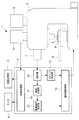
本実施形態に係る顕微鏡装置1は、図1に示されるように、顕微鏡本体2と、制御部3と、後述するマクロ画像およびミクロ画像等を表示する表示部としてのモニタ4と、画像記憶部5とを備えている。
A microscope apparatus 1 and an image acquisition method according to an embodiment of the present invention will be described below with reference to the drawings.
As shown in FIG. 1, the microscope apparatus 1 according to the present embodiment includes a microscope
顕微鏡本体2は、試料Aを搭載したスライドガラスBを載置して水平でかつ互いに直交する2方向にマクロ撮像部としての移動させるステージ6と、該ステージ6上に搭載された試料A全体を含むマクロ画像を取得するマクロカメラ7と、マクロ画像より高い解像度を有する試料Aの部分的なミクロ画像を取得するミクロ撮像部としてのミクロカメラ8と、試料Aに対して自動的に焦点位置合わせを行うオートフォーカス装置9とを備えている。
The
オートフォーカス装置9は、ステージ6を水平方向に移動させながら、試料Aに対して合焦位置を連続的に検出する(オートフォーカス動作を連続的に行う)いわゆるリアルタイムオートフォーカス装置である。
このオートフォーカス装置9は、ミクロカメラ8の光軸上に配置されている小領域に対する合焦位置が、直前の小領域における合焦位置に対して一定の移動範囲内に収まる場合にオートフォーカス動作を行い、一定の移動範囲内に収まらない場合には、直前のオートフォーカス動作を行った小領域における合焦位置を維持するようになっている。
The
The
制御部3は、CPU(中央演算処理装置)であり、マクロカメラ7により取得されたマクロ画像を処理して、スライドガラスB上の試料Aの輪郭形状を抽出する抽出部10と、該抽出部10により抽出された輪郭形状を含むようにグリッドを当てはめて、試料Aを複数の小領域に分割する領域分割部11とを備えている。ここで、小領域の大きさは、ミクロカメラ8の視野と同一に設定している。
また、制御部3は、生成された複数の小領域に対して、ミクロカメラ8によるミクロ画像の取得順序を定める撮像順序設定部12を備えている。例えば、格子状に正方配列された複数の小領域について、図2(c)に矢印Cで示されるように、配列の左上から順に、左右に蛇行しながら一筆書きで最下段まで走査する順序でミクロ画像を取得していくようになっている。
The
In addition, the
さらに、制御部3は、抽出部10により抽出された試料Aが、スライドガラスB上に複数点在するか否かを判定し、点在する場合には、各試料Aの塊を含む複数のブロックB1,B2,B3を定義するブロック設定部13を備えている。試料Aが点在するか否かについては、抽出部10により抽出された試料Aが分離独立した複数の塊を形成しているか否かによって判定するようになっている。図2に示される例では、3つのブロックB1,B2,B3が定義されるようになっている。
Furthermore, the
また、制御部3は、ブロック設定部13により定義されたブロックB1.B2,B3の情報(例えば、試料の塊の重心位置情報)を得るとともに、撮像順序設定部12により設定されたミクロ画像の取得順序の情報を得て、顕微鏡本体2を制御する顕微鏡制御部14を備えている。
顕微鏡制御部14は、上述のように複数点在する試料Aの塊にそれぞれブロックB1,B2,B3を定義した場合には、ミクロ画像の取得に先立って、各ブロックB1,B2,B3毎に、試料Aの塊の重心位置において、オートフォーカスの合焦位置の探索を行うようオートフォーカス装置9に指令するようになっている。
In addition, the
When the blocks B1, B2, and B3 are respectively defined in the lump of the sample A that is scattered in plural as described above, the
そして、合焦位置が発見されたブロックB1,B2,B3については、その合焦位置を基準としてオートフォーカス動作を行いつつミクロ画像を取得させるようになっている。一方、合焦位置が発見されなかったブロックについては、ミクロ画像を取得することなく、次のブロックにおけるオートフォーカスの合焦位置の探索を行わせるようになっている。
また、ミクロカメラ8によって取得されたミクロ画像は画像処理部15によって処理された後、画像記憶部5に記憶されるとともに、必要に応じて複数つなぎ合わせてモニタ4に表示されるようになっている。
For the blocks B1, B2, and B3 in which the in-focus positions are found, a micro image is acquired while performing an autofocus operation with reference to the in-focus positions. On the other hand, for the block in which the in-focus position has not been found, the search for the in-focus position in the next block is performed without acquiring a micro image.
In addition, the micro image acquired by the micro camera 8 is processed by the
このように構成された本実施形態に係る顕微鏡装置1を用いた画像取得方法について、以下に説明する。
本実施形態に係る画像取得方法は、図3に示されるように、スライドガラスBのマクロ画像G1を取得するマクロ画像取得ステップS1と、取得されたスライドガラスBのマクロ画像G1において試料Aを抽出する試料抽出ステップS2と、抽出された試料AがスライドガラスB上に複数点在している場合には、各試料Aの塊にそれぞれブロックB1,B2,B3を定義するブロック設定ステップS3と、各ブロックB1,B2,B3内において、試料Aを含む領域に格子状のグリッドGを当てはめて、複数の小領域Rに分割する小領域生成ステップS4とを含んでいる。
An image acquisition method using the microscope apparatus 1 according to the present embodiment configured as described above will be described below.
Image acquiring method according to the present embodiment, as shown in FIG. 3, a macro image acquiring step S1 for acquiring a macro image G 1 of the slide glass B, the sample A in the macro image G 1 of the acquired slide glass B Sample extraction step S2 for extracting the sample, and when a plurality of extracted samples A are scattered on the slide glass B, a block setting step S3 for defining blocks B1, B2, and B3 for each sample A block, respectively. In each of the blocks B1, B2, and B3, a small area generation step S4 that divides the area including the sample A into a plurality of small areas R by applying the grid G to the area.
マクロ画像取得ステップS1においては、図2(a)に示されるように、マクロカメラ7により試料A全体のマクロ画像G1が取得される。
試料抽出ステップS2においては、制御部3に備えられた抽出部10により、マクロ画像G1から試料Aの輪郭形状が抽出される。
そして、小領域生成ステップS3においては、制御部3に備えられた領域分割部11により、図2(b)に示されるように、抽出部10によって抽出された輪郭形状を含むようにグリッドGが当てはめられ、試料Aが複数の小領域Rに分割される。
In the macro image acquiring step S1, as shown in FIG. 2 (a), the macro image G 1 of the entire sample A is obtained by the
In sampling step S2 is by the
In the small region generation step S3, the grid G is formed so as to include the contour shape extracted by the
この時点で、制御部3は、生成された複数の小領域Rについてミクロ画像を取得する順序を決定する(順序決定ステップS5)。制御部3は、図2(c)に矢印Cで示されるように、正方配列された複数の小領域Rのうちの左上の小領域R0から順に、左右に蛇行しながら最下段まで走査するようにミクロ画像の取得順序を決定する。したがって、ミクロ画像の取得は、小領域R内に部分的に試料Aが存在するような、試料Aの輪郭を含む小領域(取得開始小領域)R0から開始されるようになっている。
At this point, the
また、本実施形態に係る画像取得方法は、まず、設定されたブロックB1について、オートフォーカスの合焦位置を探索する合焦探索ステップS6と、合焦位置が発見された場合に(ステップS7)、そのブロックB1におけるオートフォーカス動作を行って合焦位置を設定する合焦位置設定ステップS9と、いずれかの小領域Rから、該小領域R内の試料Aに対しオートフォーカス動作を行いながらマクロ画像よりも解像度の高いミクロ画像を取得するミクロ画像取得ステップS10とを含んでいる。 In the image acquisition method according to the present embodiment, first, in the set block B1, the focus search step S6 for searching for the focus position of autofocus, and when the focus position is found (step S7). The focus position setting step S9 for setting the focus position by performing the autofocus operation in the block B1, and the macro while performing the autofocus operation from any one of the small regions R to the sample A in the small region R. And a micro image acquisition step S10 for acquiring a micro image having a resolution higher than that of the image.
合焦探索ステップS6は、各ブロックB1,B2,B3毎に、当該ブロックB1,B2,B3のミクロ画像取得に際してのオートフォーカス動作の基準となる合焦位置を探索するステップであり、ブロックB1,B2,B3内でのミクロ画像取得時にオートフォーカス動作によって合焦位置を試料Aの起伏に追従させる場合のオートフォーカス範囲よりも広い範囲にわたって合焦位置の探索を行うようになっている。この合焦探索ステップS6は、試料Aが多く存在する小領域、例えば、ブロックB1,B2,B3の重心近傍に位置する小領域Rにミクロカメラ8の光軸を一致させて行われる。なお、この合焦探索ステップS6は、ブロックB1,B2,B3の重心を含む小領域Rの中心部にミクロカメラ8の光軸を一致させて行ってもよい。 The in-focus search step S6 is a step for searching for the in-focus position that is a reference for the autofocus operation when acquiring the micro images of the blocks B1, B2, and B3 for each of the blocks B1, B2, and B3. When the micro image is acquired in B2 and B3, the in-focus position is searched over a wider range than the auto-focus range when the in-focus position follows the undulation of the sample A by the auto-focus operation. This focus search step S6 is performed by making the optical axis of the micro camera 8 coincide with a small region where a lot of the sample A exists, for example, a small region R located near the center of gravity of the blocks B1, B2, and B3. This focus search step S6 may be performed by aligning the optical axis of the micro camera 8 with the central portion of the small region R including the center of gravity of the blocks B1, B2, and B3.
ミクロ画像取得ステップS10においては、制御部3に備えられた顕微鏡制御部14がステージ6を作動させて、順序決定ステップS5において決定された取得開始小領域R0の中央部をミクロカメラ8の光軸上に配置し、合焦位置設定ステップS9において設定された合焦位置から、オートフォーカス装置9によるオートフォーカス動作が行われ、ミクロカメラ8によるミクロ画像の取得が行われる。ミクロ画像取得ステップS10においては、これらの動作が、順序決定ステップS5によって決定された順序に従って全ての小領域Rに対して繰り返される。
In the micro image acquisition step S10, the
ここで、合焦探索ステップS6で探索した小領域Rの中央部がミクロカメラ8の光軸上に配置されている状態から取得開始小領域R0の中央部がミクロカメラ8の光軸上に配置される状態に移動するときも、オートフォーカス装置9によるオードフォーカス動作は行われている。
Here, from the state in which the central portion of the small region R searched in the focus search step S6 is arranged on the optical axis of the micro camera 8, the central portion of the acquisition starting small region R 0 is on the optical axis of the micro camera 8. The autofocus operation by the
したがって、顕微鏡制御部14は、取得開始小領域R0の中央部がミクロカメラ8の光軸上に配置されるまでの間に、ミクロカメラ8の光軸上に試料Aが存在しなくなった場合、試料Aに対して合焦位置が検出できなくなる直前の合焦位置すなわちミクロカメラ8の光軸上に試料Aが存在しなくなる直前の合焦位置を維持するように制御する。
そして、ミクロカメラ8は、取得開始小領域R0の中央部がミクロカメラ8の光軸上に配置された時点で、最初のミクロ画像の取得が行われる。
Therefore, the
The micro camera 8 acquires the first micro image when the center of the acquisition start small region R 0 is arranged on the optical axis of the micro camera 8.
その後、取得開始小領域R0の中央部がミクロカメラ8の光軸上に配置されている状態から取得開始小領域R0に隣接する小領域Rの中央部がミクロカメラ8の光軸上に配置される状態に移動するときも、オートフォーカス装置9によるオードフォーカス動作は行われる。
そして、ミクロカメラ8は、取得開始小領域R0に隣接する小領域Rの中央部がミクロカメラ8の光軸上に配置された時点で、次のミクロ画像の取得が行われる。
Thereafter, from the state in which the central portion of the acquisition start small region R 0 is arranged on the optical axis of the micro camera 8, the central portion of the small region R adjacent to the acquisition start small region R 0 is on the optical axis of the micro camera 8. The autofocus operation by the
The micro camera 8 acquires the next micro image when the center of the small area R adjacent to the acquisition start small area R 0 is arranged on the optical axis of the micro camera 8.
一方、合焦探索ステップS6において合焦位置が発見されなかった場合には(ステップS7)、当該ブロックB1におけるミクロ画像の取得を行うことなく、対象とするブロックを次のブロックB2に変更し(ステップS8)、合焦探索ステップS6から行わせる。
そして、全てのブロックB1,B2,B3について処理が終了するまでステップS6〜S10を繰り返す(ステップS11)。
On the other hand, when the focus position is not found in the focus search step S6 (step S7), the target block is changed to the next block B2 without acquiring the micro image in the block B1 ( Step S8), starting from the focus search step S6.
Then, steps S6 to S10 are repeated until the processing is completed for all the blocks B1, B2, and B3 (step S11).
このように構成された本実施形態に係る顕微鏡装置1および画像取得方法によれば、取得開始領域R0におけるミクロ画像の取得に先立って、スライドガラスB上に試料Aが点在している場合には、ブロック設定ステップS3によって試料Aの塊毎にブロックB1,B2,Bが定義されるとともに、ブロックB1,B2,B3毎に合焦探索ステップS7が行われて合焦位置が探索されるので、ブロックB1,B2,B3間に試料Aの高低差が発生している場合においても、オートフォーカス動作を失敗することなく、より確実に試料Aの各小領域Rの鮮明なミクロ画像を取得することができるという利点がある。 According to the microscope apparatus 1 and the image acquisition method according to the present embodiment configured as described above, when the samples A are scattered on the slide glass B prior to the acquisition of the micro image in the acquisition start region R0 . The block setting step S3 defines the blocks B1, B2, and B for each block of the sample A, and the focus search step S7 is performed for each of the blocks B1, B2, and B3 to search for the in-focus position. Therefore, even when there is a height difference of the sample A between the blocks B1, B2, and B3, a clear micro image of each small region R of the sample A can be obtained more reliably without failing the autofocus operation. There is an advantage that you can.
すなわち、合焦探索ステップS7においては、ミクロ画像取得時におけるオートフォーカス範囲よりも範囲を広げて合焦位置の探索が行われるので、ブロックB1,B2,B間で試料Aの高低差が発生していても、より確実に合焦位置を発見することができる。そして、各小領域Rのミクロ画像の取得時には、オートフォーカス範囲を通常の狭い範囲に戻した後に、上記のようにして発見された合焦位置を基準としてオートフォーカス動作を行わせる。これにより、ブロックB1,B2,B3間に試料Aの高低差が存在していても、各ブロックB1,B2,B3におけるミクロ画像取得時に、オートフォーカス動作に失敗することを防止することができる。 That is, in the focus search step S7, since the focus position is searched with a range wider than the autofocus range at the time of micro image acquisition, the height difference of the sample A occurs between the blocks B1, B2, and B. Even if it is, it can discover a focus position more reliably. When acquiring the micro image of each small region R, the autofocus range is returned to the normal narrow range, and then the autofocus operation is performed based on the in-focus position found as described above. Thereby, even if there is a height difference of the sample A between the blocks B1, B2, and B3, it is possible to prevent the autofocus operation from failing at the time of micro image acquisition in each of the blocks B1, B2, and B3.
なお、本実施形態においては、合焦探索ステップS6において合焦位置が発見されなかったブロックについては、単に、ミクロ画像の取得を行うことなく次のブロックの処理を進めることとしたが、これに代えて、図4に示されるように、合焦位置が発見されなかったブロックには、画像処理部15によって標識を付して(ステップS12)、次のブロックの処理へ進行させることとしてもよい。 In the present embodiment, for the block in which the in-focus position has not been found in the in-focus search step S6, the processing of the next block is simply performed without acquiring the micro image. Instead, as shown in FIG. 4, a block for which the in-focus position has not been found may be marked by the image processing unit 15 (step S <b> 12), and the process may proceed to the next block. .
標識としては、モニタ4に表示されているマクロ画像中において該当するブロックを線で囲んだり、該当するブロックの存在する領域に周囲から判別しやすい色を付したりすることが挙げられる。
このようにすることで、ミクロ画像取得の終了後に、モニタ4に表示されている標識が付された領域については、合焦探索の結果、合焦位置が発見されなかったためにミクロ画像が取得されなかったことを一目で確認することができるという利点がある。
Examples of the sign include surrounding the corresponding block in a macro image displayed on the monitor 4 with a line, or adding a color that makes it easy to distinguish the area where the corresponding block exists from the surroundings.
In this way, after the micro image acquisition is completed, the micro image is acquired for the region with the mark displayed on the monitor 4 because the focus position is not found as a result of the focus search. There is an advantage that it can be confirmed at a glance that there was not.
また、上記実施形態においては、マクロ画像を取得するマクロカメラ7とミクロ画像を取得するミクロカメラ8とを別個に設けたが、単一のカメラによってマクロ画像およびミクロ画像の両方を取得することにしてもよい。
In the above embodiment, the
1 顕微鏡装置
7 マクロカメラ(マクロ撮像部)
8 ミクロカメラ(ミクロ撮像部)
9 オートフォーカス装置(ミクロ撮像部)
10 抽出部
11 領域分割部
13 ブロック設定部
15 画像処理部
A 試料
B スライドガラス
B1,B2,B3 ブロック
G1 マクロ画像
R 小領域
S1 マクロ画像取得ステップ
S2 試料抽出ステップ
S3 ブロック設定ステップ
S4 小領域生成ステップ
S6 合焦探索ステップ
S10 ミクロ画像取得ステップ
1
8 Micro camera (micro imaging unit)
9 Autofocus device (micro imaging unit)
DESCRIPTION OF
Claims (5)
該マクロ撮像部により取得されたスライドガラスのマクロ画像において、試料を抽出する抽出部と、
該抽出部により抽出された試料が複数点在している場合に、各試料の塊を含む複数のブロックを定義するブロック設定部と、
該ブロック設定部により定義されたブロック内において、試料を含む領域を複数の小領域に分割する領域分割部と、
該領域分割部により生成された各小領域について、該小領域内の試料に対しオートフォーカス動作を行いながら前記マクロ画像よりも解像度の高いミクロ画像を取得するミクロ撮像部とを備え、
該ミクロ撮像部が、前記ブロック設定部により設定されたブロック毎に、オートフォーカスの合焦位置を探索する顕微鏡装置。 A macro imaging unit that acquires a macro image of a slide glass mounted with a sample;
In the macro image of the slide glass acquired by the macro imaging unit, an extraction unit for extracting a sample;
A block setting unit for defining a plurality of blocks including a lump of each sample when a plurality of samples extracted by the extraction unit are scattered;
In the block defined by the block setting unit, a region dividing unit that divides the region including the sample into a plurality of small regions;
For each small region generated by the region dividing unit, a micro imaging unit that acquires a micro image having a higher resolution than the macro image while performing an autofocus operation on a sample in the small region,
A microscope apparatus in which the micro imaging unit searches for a focus position of autofocus for each block set by the block setting unit.
該マクロ画像取得ステップにより取得されたスライドガラスのマクロ画像において試料を抽出する試料抽出ステップと、
該試料抽出ステップにより抽出された試料が複数点在している場合に、各試料の塊を含む複数のブロックを定義するブロック設定ステップと、
該ブロック設定ステップにおいて設定されたブロック内において、試料を含む領域を複数の小領域に分割する小領域生成ステップと、
前記ブロック設定ステップにおいて設定されたブロック毎に、オートフォーカスの合焦位置を探索する合焦探索ステップと、
該合焦探索ステップにおいて、合焦位置が発見されたブロックについて、いずれかの前記小領域から、該小領域内の試料に対しオートフォーカス動作を行いながら前記マクロ画像よりも解像度の高いミクロ画像を取得するミクロ画像取得ステップとを含む画像取得方法。 A macro image acquisition step for acquiring a macro image of a slide glass mounted with a sample;
A sample extraction step of extracting a sample in the macro image of the slide glass acquired by the macro image acquisition step;
A block setting step for defining a plurality of blocks including a lump of each sample when a plurality of samples extracted by the sample extraction step are scattered;
In the block set in the block setting step, a small region generating step for dividing the region including the sample into a plurality of small regions;
For each block set in the block setting step, an in-focus search step for searching for an in-focus position for autofocus,
In the focus search step, a micro image having a resolution higher than that of the macro image is performed from any one of the small areas while performing an autofocus operation on a sample in the small area. An image acquisition method including a micro image acquisition step of acquiring.
Priority Applications (2)
| Application Number | Priority Date | Filing Date | Title |
|---|---|---|---|
| JP2010140790A JP5537281B2 (en) | 2010-06-21 | 2010-06-21 | Microscope device and image acquisition method |
| US13/160,201 US8890947B2 (en) | 2010-06-21 | 2011-06-14 | Microscope apparatus and method for image acquisition of specimen slides having scattered specimens |
Applications Claiming Priority (1)
| Application Number | Priority Date | Filing Date | Title |
|---|---|---|---|
| JP2010140790A JP5537281B2 (en) | 2010-06-21 | 2010-06-21 | Microscope device and image acquisition method |
Publications (2)
| Publication Number | Publication Date |
|---|---|
| JP2012003197A true JP2012003197A (en) | 2012-01-05 |
| JP5537281B2 JP5537281B2 (en) | 2014-07-02 |
Family
ID=45352173
Family Applications (1)
| Application Number | Title | Priority Date | Filing Date |
|---|---|---|---|
| JP2010140790A Active JP5537281B2 (en) | 2010-06-21 | 2010-06-21 | Microscope device and image acquisition method |
Country Status (2)
| Country | Link |
|---|---|
| US (1) | US8890947B2 (en) |
| JP (1) | JP5537281B2 (en) |
Cited By (4)
| Publication number | Priority date | Publication date | Assignee | Title |
|---|---|---|---|---|
| JP2013167816A (en) * | 2012-02-16 | 2013-08-29 | Sony Corp | Imaging apparatus, imaging control program and imaging method |
| JP2014215582A (en) * | 2013-04-30 | 2014-11-17 | オリンパス株式会社 | Confocal microscope device |
| JPWO2014006964A1 (en) * | 2012-07-04 | 2016-06-02 | ソニー株式会社 | Information processing apparatus, information processing method, program, and microscope system |
| WO2020110712A1 (en) * | 2018-11-27 | 2020-06-04 | オムロン株式会社 | Inspection system, inspection method, and program |
Families Citing this family (12)
| Publication number | Priority date | Publication date | Assignee | Title |
|---|---|---|---|---|
| ES2617664T3 (en) | 2009-03-11 | 2017-06-19 | Sakura Finetek U.S.A., Inc. | Autofocus procedure and autofocus device |
| US10139613B2 (en) | 2010-08-20 | 2018-11-27 | Sakura Finetek U.S.A., Inc. | Digital microscope and method of sensing an image of a tissue sample |
| JP6455829B2 (en) * | 2013-04-01 | 2019-01-23 | キヤノン株式会社 | Image processing apparatus, image processing method, and program |
| DE102013103971A1 (en) | 2013-04-19 | 2014-11-06 | Sensovation Ag | Method for generating an overall picture of an object composed of several partial images |
| JP6127926B2 (en) * | 2013-11-11 | 2017-05-17 | ソニー株式会社 | Image processing apparatus and image processing method |
| US10007102B2 (en) | 2013-12-23 | 2018-06-26 | Sakura Finetek U.S.A., Inc. | Microscope with slide clamping assembly |
| US11280803B2 (en) | 2016-11-22 | 2022-03-22 | Sakura Finetek U.S.A., Inc. | Slide management system |
| CN109087356A (en) * | 2018-06-29 | 2018-12-25 | 齐鲁工业大学 | Recognition positioning method, system and the device of medicine glass slide based on machine vision |
| WO2021104776A1 (en) * | 2019-11-29 | 2021-06-03 | Robert Bosch Gmbh | A control unit for focusing a sample and a method thereof |
| CN113395484A (en) * | 2020-03-12 | 2021-09-14 | 平湖莱顿光学仪器制造有限公司 | Method and equipment for presenting microscopic sub-video information of target object |
| CN112986239A (en) * | 2021-02-05 | 2021-06-18 | 爱威科技股份有限公司 | Layered image collection method and device, computer equipment and storage medium |
| JP2022127536A (en) * | 2021-02-19 | 2022-08-31 | 株式会社キーエンス | Enlarging observation device, enlarged image observation method, enlarged image observation program, and computer-readable recording medium, and apparatus storing program |
Citations (3)
| Publication number | Priority date | Publication date | Assignee | Title |
|---|---|---|---|---|
| JPH063597A (en) * | 1992-06-22 | 1994-01-14 | Olympus Optical Co Ltd | Microscope still picture observing system |
| JP2001091846A (en) * | 1999-09-24 | 2001-04-06 | Olympus Optical Co Ltd | Microscopic image transferring system |
| JP2004108947A (en) * | 2002-09-18 | 2004-04-08 | Olympus Corp | Height measuring method and confocal optical measuring device |
Family Cites Families (5)
| Publication number | Priority date | Publication date | Assignee | Title |
|---|---|---|---|---|
| JP3863993B2 (en) | 1998-03-18 | 2006-12-27 | オリンパス株式会社 | microscope |
| US20060078217A1 (en) * | 2004-05-20 | 2006-04-13 | Seiko Epson Corporation | Out-of-focus detection method and imaging device control method |
| JP4917329B2 (en) | 2006-03-01 | 2012-04-18 | 浜松ホトニクス株式会社 | Image acquisition apparatus, image acquisition method, and image acquisition program |
| JP5168121B2 (en) | 2008-12-12 | 2013-03-21 | カシオ計算機株式会社 | LIGHT EMITTING PANEL AND METHOD FOR MANUFACTURING LIGHT EMITTING PANEL |
| JP5152077B2 (en) * | 2009-04-01 | 2013-02-27 | ソニー株式会社 | Biological image presentation device, biological image presentation method and program, and biological image presentation system |
-
2010
- 2010-06-21 JP JP2010140790A patent/JP5537281B2/en active Active
-
2011
- 2011-06-14 US US13/160,201 patent/US8890947B2/en active Active
Patent Citations (3)
| Publication number | Priority date | Publication date | Assignee | Title |
|---|---|---|---|---|
| JPH063597A (en) * | 1992-06-22 | 1994-01-14 | Olympus Optical Co Ltd | Microscope still picture observing system |
| JP2001091846A (en) * | 1999-09-24 | 2001-04-06 | Olympus Optical Co Ltd | Microscopic image transferring system |
| JP2004108947A (en) * | 2002-09-18 | 2004-04-08 | Olympus Corp | Height measuring method and confocal optical measuring device |
Cited By (8)
| Publication number | Priority date | Publication date | Assignee | Title |
|---|---|---|---|---|
| JP2013167816A (en) * | 2012-02-16 | 2013-08-29 | Sony Corp | Imaging apparatus, imaging control program and imaging method |
| JPWO2014006964A1 (en) * | 2012-07-04 | 2016-06-02 | ソニー株式会社 | Information processing apparatus, information processing method, program, and microscope system |
| JP2017199026A (en) * | 2012-07-04 | 2017-11-02 | ソニー株式会社 | Information processing apparatus, information processing method, program, and microscope system |
| JP2020154317A (en) * | 2012-07-04 | 2020-09-24 | ソニー株式会社 | Medical system and medical image processing method |
| US10955655B2 (en) | 2012-07-04 | 2021-03-23 | Sony Corporation | Stitching images based on presence of foreign matter |
| JP2014215582A (en) * | 2013-04-30 | 2014-11-17 | オリンパス株式会社 | Confocal microscope device |
| WO2020110712A1 (en) * | 2018-11-27 | 2020-06-04 | オムロン株式会社 | Inspection system, inspection method, and program |
| JP2020086152A (en) * | 2018-11-27 | 2020-06-04 | オムロン株式会社 | Inspection system, inspection method, and program |
Also Published As
| Publication number | Publication date |
|---|---|
| JP5537281B2 (en) | 2014-07-02 |
| US20110316999A1 (en) | 2011-12-29 |
| US8890947B2 (en) | 2014-11-18 |
Similar Documents
| Publication | Publication Date | Title |
|---|---|---|
| JP5537281B2 (en) | Microscope device and image acquisition method | |
| JP5555014B2 (en) | Virtual slide creation device | |
| US20140313312A1 (en) | Digital microscope and method for optimizing the work process in a digital microscope | |
| JP5221614B2 (en) | Three-dimensional confocal observation device and observation focal plane displacement / correction unit | |
| JP5447516B2 (en) | Image processing apparatus, image processing method, program, and microscope | |
| US11112952B2 (en) | Interface for display of multi-layer images in digital microscopy | |
| JP6147080B2 (en) | Microscope system, method for determining bonded area, and program | |
| JP6147079B2 (en) | Microscope system, method for determining bonded area, and program | |
| JP2013088530A (en) | Magnifying observation device | |
| JP6716383B2 (en) | Microscope system, information presentation method, program | |
| US11010914B2 (en) | Image processing device, microscope system, image processing method, and program | |
| US10721413B2 (en) | Microscopy system, microscopy method, and computer readable recording medium | |
| JP2016099370A (en) | Microscope system | |
| JP2017134115A (en) | Microscope device, and image display program | |
| JP4598492B2 (en) | Processing positioning method in charged particle beam apparatus and infrared microscope used therefor | |
| JP5019279B2 (en) | Confocal microscope and method for generating focused color image | |
| JP5718012B2 (en) | Scanning laser microscope | |
| JP6312410B2 (en) | Alignment apparatus, microscope system, alignment method, and alignment program | |
| JP2010020075A (en) | Microscope system and microscope control program | |
| JP2007122118A (en) | Image connection method | |
| JP6068010B2 (en) | Microscope system | |
| JP2006292528A (en) | Cross-sectional observation method | |
| JP2009277618A (en) | Magnetic domain structural image acquisition method and scanning transmission electron microscope | |
| JP2005156847A (en) | Confocal microscope system and program | |
| Usuki et al. | Resolution-improved digital refocusing microscope for microstructure measurement |
Legal Events
| Date | Code | Title | Description |
|---|---|---|---|
| A621 | Written request for application examination |
Free format text: JAPANESE INTERMEDIATE CODE: A621 Effective date: 20130419 |
|
| A977 | Report on retrieval |
Free format text: JAPANESE INTERMEDIATE CODE: A971007 Effective date: 20140117 |
|
| A131 | Notification of reasons for refusal |
Free format text: JAPANESE INTERMEDIATE CODE: A131 Effective date: 20140121 |
|
| A521 | Request for written amendment filed |
Free format text: JAPANESE INTERMEDIATE CODE: A523 Effective date: 20140320 |
|
| TRDD | Decision of grant or rejection written | ||
| A01 | Written decision to grant a patent or to grant a registration (utility model) |
Free format text: JAPANESE INTERMEDIATE CODE: A01 Effective date: 20140415 |
|
| A61 | First payment of annual fees (during grant procedure) |
Free format text: JAPANESE INTERMEDIATE CODE: A61 Effective date: 20140425 |
|
| R151 | Written notification of patent or utility model registration |
Ref document number: 5537281 Country of ref document: JP Free format text: JAPANESE INTERMEDIATE CODE: R151 |
|
| S531 | Written request for registration of change of domicile |
Free format text: JAPANESE INTERMEDIATE CODE: R313531 |
|
| R350 | Written notification of registration of transfer |
Free format text: JAPANESE INTERMEDIATE CODE: R350 |
|
| R250 | Receipt of annual fees |
Free format text: JAPANESE INTERMEDIATE CODE: R250 |
|
| R250 | Receipt of annual fees |
Free format text: JAPANESE INTERMEDIATE CODE: R250 |
|
| R250 | Receipt of annual fees |
Free format text: JAPANESE INTERMEDIATE CODE: R250 |
|
| R250 | Receipt of annual fees |
Free format text: JAPANESE INTERMEDIATE CODE: R250 |
|
| S111 | Request for change of ownership or part of ownership |
Free format text: JAPANESE INTERMEDIATE CODE: R313111 |
|
| R371 | Transfer withdrawn |
Free format text: JAPANESE INTERMEDIATE CODE: R371 |
|
| S111 | Request for change of ownership or part of ownership |
Free format text: JAPANESE INTERMEDIATE CODE: R313111 |
|
| R371 | Transfer withdrawn |
Free format text: JAPANESE INTERMEDIATE CODE: R371 |
|
| S111 | Request for change of ownership or part of ownership |
Free format text: JAPANESE INTERMEDIATE CODE: R313111 |
|
| R350 | Written notification of registration of transfer |
Free format text: JAPANESE INTERMEDIATE CODE: R350 |
|
| R250 | Receipt of annual fees |
Free format text: JAPANESE INTERMEDIATE CODE: R250 |
|
| R250 | Receipt of annual fees |
Free format text: JAPANESE INTERMEDIATE CODE: R250 |