JP6068010B2 - Microscope system - Google Patents
Microscope system Download PDFInfo
- Publication number
- JP6068010B2 JP6068010B2 JP2012129720A JP2012129720A JP6068010B2 JP 6068010 B2 JP6068010 B2 JP 6068010B2 JP 2012129720 A JP2012129720 A JP 2012129720A JP 2012129720 A JP2012129720 A JP 2012129720A JP 6068010 B2 JP6068010 B2 JP 6068010B2
- Authority
- JP
- Japan
- Prior art keywords
- imaging
- image
- image data
- unit
- area
- Prior art date
- Legal status (The legal status is an assumption and is not a legal conclusion. Google has not performed a legal analysis and makes no representation as to the accuracy of the status listed.)
- Expired - Fee Related
Links
Images


Description
本発明は、拡大して観察すべき被写体を撮像して撮像された画像を出力する顕微鏡システムに関する。 The present invention relates to a microscope system that images a subject to be magnified and observes and outputs the captured image.
例えば、従来型の光学顕微鏡においても、デジタルカメラを装着し、デジタルカメラからモニタに拡大画像を出力可能になっているものがあったが、近年、撮像素子が組み込まれ、接眼レンズがなく、モニタに出力された拡大画像の観察、撮像を行うタイプの顕微鏡が増加している(例えば、特許文献1参照)。 For example, some conventional optical microscopes are equipped with a digital camera and can output an enlarged image from the digital camera to the monitor. However, in recent years, an image sensor is incorporated, there is no eyepiece, and the monitor There are an increasing number of types of microscopes that perform observation and imaging of the magnified image output to (see, for example, Patent Document 1).
ところで、光学顕微鏡は、比較的単純な装置であり、使用者が操作できるのは、例えば、レンズ交換による倍率の変更、ピント合わせ、XYステージでの対象物の位置合わせ等である。いずれも比較的単純な操作であるが、顕微鏡の操作に慣れていない人にとっては、意外と難しい作業である。例えば、ピント合わせにおいては、光学顕微鏡は、通常のカメラに比較して焦点深度が小さく、かつ、ピントが合うような状況では対物レンズと対象物とが近接するので、対物レンズを対象物に接触させる虞があり、対象物にピントを合わせるのに繊細な操作が必要になる。 By the way, the optical microscope is a relatively simple device, and the user can operate, for example, change of magnification by exchanging lenses, focusing, positioning of an object on an XY stage, and the like. Both are relatively simple operations, but are surprisingly difficult for those who are not used to operating the microscope. For example, in focusing, the optical microscope has a smaller depth of focus than a normal camera, and the objective lens and the object are close to each other in a situation where the object is in focus. Therefore, a delicate operation is required to focus on the object.
また、XYステージで対象物または対象物内の観察位置を視野の中央部分に移動するのも、例えば、初心者には難しい操作になる。
例えば、比較的小さな倍率の場合に、視野の範囲が広く、比較的簡単に対象物またはその被観察位置を見つけて視野の中央部分に配置できるが、この状態で、倍率を高めた際に、視野が狭くなることで、被観察位置となる部分が視野内に入らなかった場合に、どこに被観察位置があるのかわからなくなり、XYステージを操作して、狭い視野内に被観察位置を導くことが難しい。
Also, moving the object or the observation position in the object to the center of the field of view on the XY stage is an operation difficult for beginners, for example.
For example, when the magnification is relatively small, the range of the field of view is wide, and it is relatively easy to find the object or its observation position and place it in the center of the field of view. By narrowing the field of view, if the part to be observed does not enter the field of view, it becomes impossible to know where the position to be observed is, and the XY stage is operated to guide the position to be observed within the narrow field of view. Is difficult.
ピント合わせにおいては、顕微鏡用のオートフォーカス装置が開発されており、自動化可能だが、汎用の顕微鏡で様々な種類の対象物を拡大表示する場合に、XYステージにおける対象物(被観察位置)の位置合わせを自動化することが難しい。 In focusing, an autofocus device for microscopes has been developed and can be automated, but when magnifying and displaying various types of objects with a general-purpose microscope, the position of the object (observation position) on the XY stage It is difficult to automate the alignment.
本発明は、上記事情に鑑みてなされたものであり、顕微鏡で対象物(被写体)を拡大して表示する場合に、対象物の必要とされる部分の位置合わせを不要とし、対象物を撮像した画像データから対象物の必要とされる範囲の拡大画像を得られる顕微鏡システムを提供することを目的とする。 The present invention has been made in view of the above circumstances, and when a target object (subject) is enlarged and displayed with a microscope, it is not necessary to align a required portion of the target object, and the target object is imaged. It is an object of the present invention to provide a microscope system that can obtain an enlarged image of a required range of an object from the obtained image data.
上記課題を解決するために、本発明の顕微鏡システムは、被写体を拡大して撮像するための顕微鏡システムであって、
被写体の画像を表示する表示手段と、
前記被写体の像を撮像エリアに拡大して結像させる光学結像手段と、
画素が縦横に並んだ撮像素子を備え、画像信号を出力する撮像手段と、
前記撮像手段を、前記撮像素子の画像を撮像する撮像領域より広い前記撮像エリア内で、最も短い単位移動距離として、1/2画素に対応する長さより長く、かつ、1/2画素に対応する長さの奇数倍になる長さ単位でX方向とY方向とに移動させる移動手段と、
前記移動手段により移動された前記撮像手段から画像信号として入力する複数箇所で撮像された複数の画像を繋ぎ合わせるように、前記画像信号を処理するとともに、この処理により繋げられた複数の画像からなる結合画像データを生成する信号処理手段と、
前記信号処理手段から出力された前記結合画像データを記憶し、記憶した前記結合画像データを前記表示手段に出力する画像処理手段と、
操作者が操作するとともに操作に基づいた信号を出力する操作手段と、
を備え、
前記画像処理手段は、前記操作手段から出力された信号に基づいて、記憶された前記結合画像データ中の任意の範囲を、任意の拡大倍率で拡大して前記表示手段に出力し、
前記撮像エリアは、前記撮像領域に略対応する大きさの複数の分割領域に分割され、
前記移動手段は、前記撮像領域が各分割領域に順次配置されるように前記撮像手段を移動させるとともに、各分割領域で前記撮像手段をX方向およびY方向にそれぞれ前記単位移動距離だけ移動させ、
前記撮像手段は、各分割領域内の異なる位置毎に撮像を繰り返し、
前記信号処理手段は、各分割領域で複数回撮像された画像を一つに合成するとともに、各分割領域で合成された画像を繋ぎ合わせた画像データを生成して出力することを特徴とする。
In order to solve the above problems, a microscope system of the present invention is a microscope system for enlarging and imaging a subject,
Display means for displaying an image of the subject;
Optical imaging means for enlarging and forming an image of the subject in an imaging area;
An image pickup means including an image pickup element in which pixels are arranged in rows and columns and outputting an image signal;
The imaging means is longer than the length corresponding to 1/2 pixel and corresponds to 1/2 pixel as the shortest unit movement distance in the imaging area wider than the imaging area for imaging the image of the imaging element. Moving means for moving in the X direction and the Y direction in units of length that is an odd multiple of the length ;
The image signal is processed so as to connect a plurality of images picked up at a plurality of positions inputted as image signals from the image pickup means moved by the moving means, and a plurality of images connected by this processing are included. Signal processing means for generating combined image data;
Image processing means for storing the combined image data output from the signal processing means, and outputting the stored combined image data to the display means;
Operation means for operating the operator and outputting a signal based on the operation;
With
The image processing means enlarges an arbitrary range in the stored combined image data at an arbitrary magnification based on the signal output from the operation means, and outputs the enlarged range to the display means .
The imaging area is divided into a plurality of divided areas having a size substantially corresponding to the imaging area,
The moving unit moves the imaging unit so that the imaging region is sequentially arranged in each divided region, and moves the imaging unit in each divided region by the unit moving distance in the X direction and the Y direction,
The imaging means repeats imaging at different positions in each divided area,
The signal processing unit synthesizes the images captured a plurality of times in each divided region into one, and generates and outputs image data obtained by joining the images synthesized in each divided region .
このような構成によれば、光学結像手段により画像エリアに例えば被写体の広い範囲の像を結像させ、この広い範囲に結像された像を移動手段により移動する撮像手段により撮像することができる。例えば、移動する撮像手段により画像エリア全体を撮像できる。
この際に撮像素子の単位面積当たり画素数は、画像エリアを広くしても変化せず、撮像手段の撮像素子の画像を撮像する撮像領域の面積と、撮像領域内の画素数(有効なフォトトランジスタやフォトダイオード等のセンサの数)により決まる。
According to such a configuration, for example, an image of a wide range of a subject can be formed on the image area by the optical imaging unit, and the image formed on the wide range can be captured by the imaging unit that moves by the moving unit. it can. For example, the entire image area can be imaged by moving imaging means.
At this time, the number of pixels per unit area of the image sensor does not change even when the image area is widened. The number of sensors such as transistors and photodiodes).
したがって、画像エリアを広くするとともに、被写体のより広い範囲を画像エリアに結像させることにより、被写体の広い範囲を解像度を低下させることなく撮像して画像データを得ることができる。この場合に、通常の顕微鏡での作業のように被写体となるサンプルをX−Yステージ上で縦横に移動し、観察すべき範囲を探して拡大するような作業を行う必要はない。なお、本発明の顕微鏡システムでは、X−Yステージを設けなくともよく、サンプル(被写体)をセットする際に簡単に位置を合わせればよい。画像処理手段により撮像されて記憶された画像データの任意の範囲を、任意の倍率で表示手段に表示できるので、被写体を拡大して撮像した後に、被写体の撮像された範囲内の任意の位置を拡大して観察することができる。 Therefore, by widening the image area and forming a wider range of the subject in the image area, it is possible to capture the wide range of the subject without reducing the resolution and obtain image data. In this case, it is not necessary to perform an operation of moving a sample to be a subject vertically and horizontally on an XY stage so as to search and enlarge an area to be observed as in an ordinary microscope operation. In the microscope system of the present invention, it is not necessary to provide an XY stage, and the position may be simply adjusted when setting a sample (subject). Since an arbitrary range of image data captured and stored by the image processing means can be displayed on the display means at an arbitrary magnification, after the subject is enlarged and imaged, an arbitrary position within the imaged range of the subject is displayed. It can be magnified and observed.
また、この際には、上述のように解像度(単位面積当たりの画素数)を低下させることなく、被写体の広い範囲を撮像可能なので、表示手段に撮像された画像データの任意の範囲をデジタルズームで拡大する際に解像度が下がり過ぎるのを防止できる。
以上のことから、顕微鏡の操作に不慣れな使用者であっても、顕微鏡を操作することなく、表示手段を見ながら画像処理手段を操作することにより容易に被写体の見たい部分を拡大して見ることができる。
In this case, since a wide range of the subject can be imaged without reducing the resolution (number of pixels per unit area) as described above, any range of the image data imaged on the display means can be digitally zoomed. It is possible to prevent the resolution from being lowered too much when enlarging.
From the above, even a user who is unfamiliar with the operation of the microscope can easily enlarge the portion of the subject to be viewed by operating the image processing means while viewing the display means without operating the microscope. be able to.
本発明の上記構成において、前記画像処理手段は、操作者が操作するとともに操作に基づいた信号を出力する操作手段を備え、前記操作手段から出力された信号に基づいて、記憶された前記画像データの観察すべき範囲を決定し、決定された範囲を前記操作手段から出力された信号に基づいて決定された拡大倍率で前記表示手段に表示することが好ましい。 In the above-described configuration of the present invention, the image processing unit includes an operation unit that is operated by an operator and outputs a signal based on the operation, and the stored image data based on the signal output from the operation unit It is preferable that the range to be observed is determined and the determined range is displayed on the display unit at an enlargement magnification determined based on a signal output from the operation unit.
このような構成によれば、使用者(操作者)は、顕微鏡で上述のように解像度を低下させることなく、被写体の広い範囲の画像データを取得して記憶しておくことにより、いつでも表示手段を見ながら操作手段を操作して被写体の観察すべき部分を探し出し、探し出された部分を表示手段により大きく拡大して観察することができる。また、画像データを保管しておけば、被写体の最初のときとは異なる部分を観察する必要が生じた場合でも、顕微鏡で被写体を撮像することなく、新たに観察する必要が生じた部分を拡大して表示手段に表示することができる。 According to such a configuration, the user (operator) can always display the display means by acquiring and storing image data of a wide range of the subject without reducing the resolution with the microscope as described above. It is possible to search the portion of the subject to be observed by operating the operating means while viewing the image, and to observe the enlarged portion by the display means. Also, if the image data is stored, even if it is necessary to observe a different part from the first time of the subject, the part that needs to be newly observed can be enlarged without imaging the subject with a microscope. Can be displayed on the display means.
本発明の上記構成において、前記撮像エリアは、前記撮像領域に略対応する大きさの複数の分割領域に分割され、
前記移動手段は、前記撮像領域が各分割領域に順次配置されるように前記撮像手段を移動させ、かつ、各分割領域に移動した前記撮像領域に結像された前記被写体の像を複数回繰り返し撮像し、
前記移動手段は、前記撮像手段が各分割領域のそれぞれで複数回撮像を繰り返す際に、前記撮像手段の前記撮像素子の各画素が、前記分割領域での最初の撮影時の前記撮像素子の画素の配置における前記画素どうしの間に配置されるように前記撮像手段を移動させ、
前記信号処理手段は、各分割領域で複数回撮像された画像を一つに合成するとともに、各分割領域で合成された画像を繋ぎ合わせた画像データを生成して出力することが好ましい。
In the above-described configuration of the present invention, the imaging area is divided into a plurality of divided areas having a size substantially corresponding to the imaging area,
The moving means moves the imaging means so that the imaging area is sequentially arranged in each divided area, and repeats the image of the subject formed in the imaging area moved to each divided area a plurality of times. Image
When the imaging unit repeats imaging a plurality of times in each of the divided regions, each pixel of the imaging device of the imaging unit is a pixel of the imaging device at the time of first shooting in the divided region. Moving the imaging means to be arranged between the pixels in the arrangement of
It is preferable that the signal processing unit synthesizes the images captured a plurality of times in each divided region into one, and generates and outputs image data obtained by joining the images synthesized in each divided region.
このような構成によれば、広い範囲を撮像する際に解像度の低下を防止できるだけではなく、解像度を高めることができる。したがって、撮像された画像データの任意の範囲を任意の倍率で表示する際に、表示時の倍率を高くしても、解像度が低下し過ぎるのを防止できる。 According to such a configuration, it is possible not only to prevent a decrease in resolution when imaging a wide range, but also to increase the resolution. Therefore, when displaying an arbitrary range of captured image data at an arbitrary magnification, it is possible to prevent the resolution from being excessively lowered even if the magnification at the time of display is increased.
なお、各分割領域で複数回撮像手段で撮像する方法としては、各分割領域で連続して複数回撮影した後に次の分割領域に移動して同様に複数回の撮影を繰り返す方法や、撮像エリアの全ての分割領域で一回ずつ撮像する動作を複数回繰り返す方法や、全ての分割領域を複数グループに分け、各グループに属する分割領域において、一回ずつ撮像する動作を複数回繰り返す方法などを用いることができる。 In addition, as a method of imaging with the imaging unit multiple times in each divided area, a method in which a plurality of continuous imaging is performed in each divided area and then moved to the next divided area and the imaging is repeated a plurality of times in the same manner. The method of repeating the operation of imaging once in all the divided areas multiple times, the method of dividing all the divided areas into a plurality of groups, and the operation of imaging once in the divided areas belonging to each group, etc. Can be used.
また、信号処理手段で一つの画像データを得る方法は、各分割領域毎に複数繰り返して撮像された画像を合成した画像データを得た後に、各分割領域毎に合成された画像データを繋ぎ合わせて一つの画像データを得るものとしてもよいし、各分割領域の同じ画素配置で撮影された画像を繋ぎ合わせて画像エリア全体に対応する画像データを各分割領域での撮影回数分だけ得た後に、これら繋ぎ合わされた複数の画像データを合成して一つの画像データを得るものとしてもよい。 In addition, the method of obtaining one image data by the signal processing means is to obtain image data obtained by combining a plurality of repeatedly captured images for each divided region, and then connecting the image data combined for each divided region. It is also possible to obtain one image data, or after connecting the images taken with the same pixel arrangement in each divided area and obtaining image data corresponding to the entire image area for the number of times taken in each divided area. Alternatively, one piece of image data may be obtained by synthesizing a plurality of these connected image data.
本発明の上記構成において、前記撮像手段の前記撮像素子の各画素が、X方向とこのX方向に直交するY方向とにそれぞれ沿って並べて配置され、前記撮像手段が各分割領域で、複数回撮像を繰り返す際に、前記分割領域での最初の撮影時の前記撮像手段の前記撮像素子における画素の配置に対して、X方向に画素の配置が略1/2画素ずれた位置での撮像と、Y方向に画素の配置が略1/2画素ずれた位置での撮像と、X方向およびY方向の両方に画素の配置が略1/2画素ずれた位置での撮像とを行うことが好ましい。 In the above configuration of the present invention, the pixels of the image sensor of the imaging unit are arranged side by side along the X direction and the Y direction orthogonal to the X direction, and the imaging unit is in each divided region a plurality of times. When the imaging is repeated, the imaging at the position where the pixel arrangement is shifted by approximately ½ pixel in the X direction with respect to the pixel arrangement in the imaging element of the imaging means at the time of the first imaging in the divided region It is preferable to perform imaging at a position where the pixel arrangement is shifted by approximately ½ pixel in the Y direction and imaging at a position where the pixel arrangement is shifted by approximately ½ pixel in both the X direction and the Y direction. .
このような構成によれば、最終的に合成された画像データにおいては、最初の撮影時の画素の配置に対して、X方向に並んだ各画素の間に画素が新たに配置され、Y方向に並んだ各画素の間に画素が新たに配置され、X方向とY方向を合成した斜め方向に並んだ各画素の間に新たに画素が配置される。これにより、4倍密に画素が配置された高解像度の画像データを得ることができる。これにより画像データの任意の範囲を高倍率で表示する際に解像度の劣化を防止することができる。なお、1/2画素とは、隣り合う画素の中心間の距離の1/2であり、例えば、後述の1/2画素ピッチである。 According to such a configuration, in the finally synthesized image data, pixels are newly arranged between the pixels arranged in the X direction with respect to the arrangement of the pixels at the time of the first shooting, and the Y direction Pixels are newly arranged between the pixels arranged in the same direction, and pixels are newly arranged between the pixels arranged in the oblique direction obtained by combining the X direction and the Y direction. Thereby, high-resolution image data in which pixels are arranged four times densely can be obtained. As a result, it is possible to prevent resolution degradation when displaying an arbitrary range of image data at a high magnification. Note that the ½ pixel is ½ of the distance between the centers of adjacent pixels, for example, a ½ pixel pitch described later.
本発明の上記構成において、前記移動手段は、前記撮像手段を1/2画素に対応する長さの奇数倍になる長さ単位でX方向とY方向とに移動可能に設定され、各分割領域で前記撮像手段を移動する際に、X方向および/またはY方向に1/2画素に対応する長さの奇数倍になる長さだけ移動させることが好ましい。 In the above-described configuration of the present invention, the moving unit is set to be movable in the X direction and the Y direction in units of length that is an odd multiple of the length corresponding to 1/2 pixel. When moving the imaging means, it is preferable to move in the X direction and / or Y direction by a length that is an odd multiple of the length corresponding to 1/2 pixel.
上述ように各分割領域で最初に撮影された際の撮像素子の画素の配置に対して、各方向に1/2画素ずらすように撮像手段を移動する場合に、基本的には撮像手段を各方向に1/2画素の長さだけずらせばよいが、1/2画素の長さが短いので、精度高く1/2画素の長さだけ撮像手段を移動させることが難しい。 As described above, when moving the image pickup means so as to be shifted by 1/2 pixel in each direction with respect to the arrangement of the pixels of the image pickup element at the time of first shooting in each divided region, Although it is sufficient to shift the direction by a length of ½ pixel in the direction, it is difficult to move the imaging unit by a length of ½ pixel with high accuracy because the length of ½ pixel is short.
また、移動手段の精度を高めるには高いコストがかかるという問題があった。そこで、移動手段による撮像手段の移動の単位長さを1/2画素の長さの奇数倍とすることにより、撮像手段の単位移動長さが短くなるのを防止し、大きな単位長さで移動することができる。これにより、精度を高めるためのコストの増加を抑制することができる。また、移動手段が撮像手段を1/2画素の長さ単位で移動させる場合に比較して、1/2画素の長さの奇数倍の長さ単位で移動させることにより、移動手段による撮像手段の移動速度の向上や移動制御の簡便化を図ることができる。 Further, there is a problem that high cost is required to improve the accuracy of the moving means. Therefore, by making the unit length of the movement of the imaging means by the moving means an odd multiple of 1/2 pixel length, it is possible to prevent the unit movement length of the imaging means from being shortened and move by a large unit length. can do. Thereby, the increase in the cost for improving a precision can be suppressed. In addition, the moving means moves the image pickup means by a unit of length that is an odd multiple of the length of 1/2 pixel as compared to the case where the image pickup means is moved by a length unit of 1/2 pixel. The moving speed can be improved and the movement control can be simplified.
本発明によれば、顕微鏡における操作を簡便化できるとともに、解像度を劣化させることなく、被写体の広い範囲を撮像した画像データを用いて、顕微鏡を用いた撮像後に、顕微鏡を操作することなく、被写体の観察すべき部分を探して拡大表示することができる。 According to the present invention, the operation in the microscope can be simplified and the subject can be used without operating the microscope after imaging using the microscope using image data obtained by imaging a wide range of the subject without degrading the resolution. The portion to be observed can be searched and enlarged.
以下、図面を参照しながら本発明の第1実施形態について説明する。
図1に示すように、この実施形態の顕微鏡システムは、撮像装置(撮像部4)が内蔵されたものであり、かつ、基本的に静止画用の顕微鏡であり、撮像した静止画としての拡大画像をモニタに表示するようになっている。
Hereinafter, a first embodiment of the present invention will be described with reference to the drawings.
As shown in FIG. 1, the microscope system according to this embodiment includes an imaging device (imaging unit 4), and is basically a microscope for still images, and is enlarged as a captured still image. The image is displayed on the monitor.
この顕微鏡システムは、図1に示すように、顕微鏡システム内の顕微鏡として、被写体2(対象物)に撮像用の光を当てる照明部(照明手段)1、被写体2の拡大像を得るためのレンズ部(光学結像手段)3、撮像素子を備える撮像部(撮像手段)4、レンズ部3により被写体の拡大像が結像される撮像エリア5、撮像部4を撮像エリア5内でX−Y方向に移動するためのX−Y可動部(移動手段)6、撮像部4から出力される映像信号を処理する信号処理部(信号処理手段)7、レンズ部3、撮像部4、X−Y可動部6および信号処理部7等を制御する制御部(制御手段)8を備える。
As shown in FIG. 1, this microscope system is a microscope in the microscope system. As a microscope in the microscope system, an illumination unit (illuminating means) 1 that applies imaging light to a subject 2 (object), and a lens for obtaining an enlarged image of the subject 2 An image pickup unit (image pickup means) 4 having an image pickup element, an
また、このような顕微鏡を有する顕微鏡システムには、顕微鏡での撮像時に被写体2を表示するとともに、後述の画像処理装置21で取り扱う各種画像データを表示するためのモニタ(表示手段)22を有し、信号処理部7から出力された画像データを処理する画像処理装置21を有する。なお、画像処理装置21は、顕微鏡部分と一体に設けられた構造であってもよいし、顕微鏡部分と別体に設けられた構成でもよい。また、画像処理装置21は、パーソナルコンピュータ(PC)や、タブレット型(パッド型)の電子装置(コンピュータ)や、スマートフォン等であってもよい。また、モニタ22は、顕微鏡での撮像時に使用するモニタと、画像処理装置21で用いるモニタとに分けてもよい。
Further, the microscope system having such a microscope has a monitor (display means) 22 for displaying the subject 2 at the time of imaging with the microscope and displaying various image data handled by the
照明部1は、被写体2を適切な光量で照明する。照明部1による照明は、この実施形態において、被写体の裏面から照明して透過光で撮像する構成としている。なお、レンズ部3の方向より照明して反射光で撮像する構成としても良い。また、照明部1は、制御部8の制御により明るさの調整が可能になっている。
The
レンズ部3は、被写体2の被撮像範囲を撮像エリア5に拡大して結像させる。この顕微鏡においては、レンズ部3は、撮像部4の撮像素子の撮像領域9(図2に図示)の面積に対応じて像を結像させるのではなく、例えば、撮像素子の撮像領域9の面積より大きな面積、例えば、4倍や9倍やそれ以上の倍率の面積の撮像エリア5に対応して被写体2の像を結像させる。これは、後述のように撮像部4をX−Y可動部6により移動させて複数個所で撮像エリア5を撮像することにより、実質的に大きな面積を有する撮像素子で撮像したのと同じ画像データを得るためである。
The
これにより、画素数の多い画像データを得ることができ、画像データの一部を部分的に抜き出してモニタに拡大表示する際(デジタルズームする際)に、所定の画素数の画像データから少ない画素数の範囲を抜き出すことにより生じる画像の画素数の減少による画像の劣化を防止することができる。すなわち、撮像時の画素数を撮像部4を移動することにより増加しておくことができ、画像データの各部分を抜き出した際の抜き出された部分の画素数が多くなるようにしておくものである。 As a result, image data with a large number of pixels can be obtained, and when a part of the image data is partially extracted and enlarged and displayed on a monitor (when digital zooming is performed), the number of pixels from the image data with a predetermined number of pixels is reduced. It is possible to prevent image degradation caused by a decrease in the number of pixels of an image caused by extracting the range. That is, the number of pixels at the time of imaging can be increased by moving the imaging unit 4, and the number of pixels in the extracted portion when each portion of the image data is extracted is increased. It is.
また、レンズ部3により撮像エリア5で結像される被写体の像は、その視野範囲を広いものとする。例えば、従来の撮像装置付きの顕微鏡で最終的に撮像する際、すなわち、顕微鏡の視野内に適切な倍率で適切な範囲の被観察位置が配置されている際の視野範囲よりも大きな範囲、例えば、従来の顕微鏡の視野範囲の10倍やそれ以上の範囲が撮像エリア5で結像されるようになっている。
The subject image formed in the
この顕微鏡においては、被写体の観察すべき部分である被観察位置を適切な拡大倍率で見るか、撮像する場合に、従来のように撮像前に被観察位置を適切な拡大倍率で視野の中央に配置してから撮像するのではなく、撮像時に被写体の被観察位置を含む広い範囲を撮像して画像データを取得し、この画像データの表示に際し、例えば、低倍率で被観察位置を特定し、特定された被観察位置をデジタルズームにより高倍率で表示させることで、目的とする被観察位置(範囲)または観察に適した被観察位置を観察に適した拡大倍率で表示させるようになっている。 In this microscope, when observing the observation position of the subject at an appropriate magnification, or when imaging, the observation position is set at the center of the field of view at an appropriate magnification before imaging as in the past. Rather than taking an image after placing it, the image data is acquired by imaging a wide range including the observed position of the subject at the time of imaging, and when the image data is displayed, for example, the observed position is specified at a low magnification, By displaying the specified observation position at a high magnification by digital zoom, the target observation position (range) or the observation position suitable for observation is displayed at an enlargement magnification suitable for observation.
したがって、被写体の結像された像の撮像範囲である撮像エリア5内に含まれる被写体の範囲が上述のように最終的に観察される被観察範囲より広い範囲である必要がある。
なお、レンズ部3は、例えば、レンズ交換による倍率の変更や、ピント合わせを行う機構を有し、制御部8の制御により、倍率の変更とピント合わせが可能になっている。なお、ピント合わせは、オートフォーカスを可能にしてもよい。
Therefore, the range of the subject included in the
The
撮像部4は、例えば、デジタルカメラ等で使用される周知のCCDやCMOSの撮像素子を備えるものである。この撮像部4は、X−Y可動部6により、撮像エリア5内をX方向およびY方向に移動可能になっている。上述のように撮像部4の撮像素子の撮像領域9より広い範囲である撮像エリア5内を移動して被写体2の像を撮像するようになっている。なお、撮像部4における撮像は、制御部8に制御されるもので、後述のようにX−Y可動部6により移動させられた各移動位置で自動的に撮像を行うようになっている。
The imaging unit 4 includes, for example, a well-known CCD or CMOS imaging device used in a digital camera or the like. The imaging unit 4 can be moved in the X direction and the Y direction within the
撮像エリア5は、レンズ部3により被写体2の像が結像される平面(薄い平板上のスペース)であり、撮像領域9(撮像部4)の移動範囲となるエリアであるが、たとえば、外光を遮断するように図示しないケーシング内に配置され、レンズ部3から光が入射するようになっている。
X−Y可動部6は、周知の自動X―Yテーブルとしての機能を有するものであり、制御部8の制御により撮像部4を予め設定されたXY座標位置に移動するようになっている。
また、X−Y可動部6は、例えば、ステッピングモータとプーリとベルトにより撮像部4をX方向およびX方向に直交するY方向に移動させる。なお、リニアステッピングモータを用いるものとしてもよい。
The
The XY
In addition, the XY
信号処理部7は、後述のように撮像エリア5を複数箇所に分割して撮像された画像の画像信号を繋ぎ合わせて一つの画像データを生成する処理と、後述のように画素をずらして複数回撮像された画像の画像信号を合成して一つの画像データを生成する処理とを行う。なお、これらの処理は、周知の画像処理方法により行うことができる。
The
制御部8は、各種スイッチ、レバー、ダイヤル等を有する操作盤を備え、操作入力が可能になっている。
制御部8は、操作盤からの操作入力により照明部1の明るさの調整を行う。なお、光センサを備え。外光に対応して明るさを自動調整するものとしてもよい。
また、制御部8は、操作盤からの操作入力によりレンズ部3における倍率とピント合わせを制御する。なお、ピント合わせをオートフォーカスとしてもよい。なお、ピント合わせでは、撮像部4を撮像エリア5の所定位置に固定した状態で行うものとしてもよい。
The
The
The
また、制御部8は、撮像部4を制御して、上述のように自動で撮像を行わせる。
また、制御部8は、X−Y可動部6を制御して、撮像部4を撮像エリア5の複数の配置位置(分割領域5a〜i)に移動させる制御を行う(なお、後述の第2実施形態において、各配置位置で後述のように画素をずらすための移動を制御する)。
また、制御部8は、信号処理部7を制御し、上述の処理を行わせる。
In addition, the
Further, the
The
画像処理装置21は、記憶した画像データの拡大、縮小や、表示位置の移動を行うもので、操作手段として、各種ポイントデバイスのいずれかを備え、画像の表示位置の移動、拡大、縮小等を指示することが可能になっている。なお、モニタ22の画面にポインティングデバイスとしてタッチパネル(ペンタブレット含む)を設けるものとしてもよい。
The
次に、撮像エリア5内における撮像部4のX−Y可動部6による移動について説明する。
例えば、図2および図3に示すように、撮像エリア5内の撮像部4の撮像素子の撮像領域9の面積に対して、例えば、撮像エリア5の面積が9倍等の倍率で広くなっている。なお、撮像エリア5は、撮像領域9より大きい必要があり、少なくとも4倍以上あることが好ましく、顕微鏡のサイズやコスト的に許される範囲で広いことが好ましい。また、撮像素子の撮像領域9とは、撮像素子のフォトセンサがマトリックス状に配置されている部分であり、結像された像を撮像可能な領域である。
自動X−YテーブルとしてのX−Y可動部6により、撮像部4が移動すると、撮像部4の撮像素子の撮像領域9が撮像エリア5上を移動することになる。
Next, the movement of the imaging unit 4 in the
For example, as shown in FIGS. 2 and 3, for example, the area of the
When the imaging unit 4 is moved by the XY
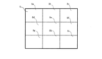
例えば、撮像エリア5の面積が撮像領域9の9個分の面積の場合(撮像エリア5と撮像領域が相似形であることが好ましい)に、撮像エリア5は、図3に示すように、撮像領域9のサイズに対応して9つの分割領域5a〜iに分割される。撮像部4の撮像領域9は、撮像エリア5の各分割領域5a〜iに移動させられる。すなわち、撮像領域9が撮像エリア5の各分割領域5a〜iに配置されるように撮像部4が9箇所の各分割領域5a〜iにX−Y可動部6により移動させられ、各分割領域5a〜iで撮像素子による撮像が行われる。なお、このような複数回の撮像において、撮像領域9の周縁部が前の撮像時の撮影領域9の周縁部と重なるように撮像部4を移動してもよい。
For example, when the area of the
図4に示すように、撮像エリア5の各分割領域5a〜iで撮像部4により撮像された例えば、9つの画像データ51〜59は、画像信号として信号処理部7に送られる。信号処理部7で撮像エリア5の各分割領域5a〜iにそれぞれ対応する例えば9つの画像データ51〜59が一つの画像データ50に繋ぎ合わされてモニタ22を備えた画像処理装置21に出力される。なお、各画像データ51〜59は、撮像エリア5の各分割領域5a〜iに結像された像を撮像した画像であり、各画像データ51〜59を、その画像データ51〜59が撮像された分割領域5a〜iの配置に対応して配置して各画像データ51,59を繋げることにより、撮像エリア5で結像された像の全体を示す画像データ50を得ることができる。
As shown in FIG. 4, for example, nine
このような顕微鏡にあっては、被写体を含む被撮像範囲の最終的に撮像されて利用される範囲より広い範囲を、撮像エリア5に結像させ、撮像エリア5より小さい撮像領域9を有する撮像部4をX−Y方向(縦横)に移動させることにより、通常の顕微鏡で撮像される被撮像範囲より広い範囲を撮像することができる。また、この際に撮像領域9を移動することで、広い被撮像範囲を撮影しているので、例えば、撮像領域9に広い被撮像範囲全体を結像させて撮像させた場合に比較して、解像度の高い画像(画素数の多い画像)を得ることができる。したがって、画像データから一部を抜き出して高倍率で表示しても、解像度が低くなり過ぎるのを防止できる。
In such a microscope, a range wider than the range that is finally captured and used in the imaging range including the subject is imaged in the
この場合に、撮像時(撮像前)に高い拡大倍率で拡大するとともに、必要とされる被観察位置が含まれた被撮像範囲を決定してから撮影を行う必要はない。すなわち、被撮像範囲のどこかに必要とされる被観察位置が含まれていればよい。この場合に被撮像範囲を広く設定しているので、被写体としてのサンプルのセット位置が正しければ、そのままピントを合わせて撮像することにより、被観察位置が含まれる画像データを得ることができる。
上述のように得られて記憶された画像データには、被観察位置を含む広い範囲が含まれているので、この広い範囲の画像データから被観察位置を観察に適した倍率で拡大するとともに、被観察位置を切り抜いた状態の画像データを作成して記憶することになる。
In this case, it is not necessary to shoot at the time of imaging (before imaging) while magnifying at a high magnification and determining an imaging range that includes a required observation position. That is, it is only necessary that the observation position required somewhere in the imaging range is included. In this case, since the imaging range is set wide, if the set position of the sample as the subject is correct, the image data including the observation position can be obtained by focusing and capturing the image as it is.
Since the image data obtained and stored as described above includes a wide range including the observed position, the observed position is enlarged from the wide range of image data at a magnification suitable for observation, and Image data in a state where the observation position is cut out is created and stored.
なお、この際に被観察位置をモニタ22上で探す場合に、表示倍率(デジタルズームの倍率)を任意に変えながら観察位置を探すことができる。すなわち、低解像度の表示として広い範囲をモニタに表示させ、広い範囲から被観察位置と思われる部分を探し、探した部分を拡大して被観察位置であることを確認する。さらに、被観察位置の表示に適した倍率および撮像範囲を設定する。この際には、実際に撮像するのではなく、記憶した画像データから被観察位置を最適なデジタルズームの倍率で表示できる状態にするために、画像データから被観察位置の画像部分を切り取ること、言い換えれば画像データから不必要な部分をトリミングすることになる。
In this case, when searching the observation position on the
したがって、顕微鏡の使用者(ユーザ)は、デジタルズーム処理により、画像を拡大することにより、任意の倍率の拡大画像を、レンズの交換なしに得ることができる。すなわち、使用者が顕微鏡に慣れておらず、顕微鏡の視野から観察すべき被観察位置を探し出し、この被観察位置を適切な倍率で拡大して表示するのに時間を要するような場合でも、この顕微鏡では、被写体の一部である被観察位置を拡大表示する目的の場合に、例えば、被写体全体を撮像して画像データを得た後に、顕微鏡に接続されたモニタ22上で画像処理装置21により、上述のように被観察位置を探し出し、探し出された被観察位置を適切な倍率で表示させることができる。
Therefore, the user (user) of the microscope can obtain an enlarged image with an arbitrary magnification without replacing the lens by enlarging the image by digital zoom processing. That is, even if the user is not used to the microscope and finds the observation position to be observed from the microscope's field of view, and it takes time to enlarge and display the observation position at an appropriate magnification, this In the microscope, for the purpose of magnifying and displaying the observed position that is a part of the subject, for example, after the entire subject is imaged to obtain image data, the
すなわち、通常顕微鏡で撮像時に行われている作業の一部を、顕微鏡での被写体の撮像後に撮像された画像データを用いて行うことができる。この場合に、モニタ22上で操作を行うことができるので、顕微鏡に不慣れな使用者でも、被観察位置を拡大して表示する操作を容易に行うことができる。
That is, a part of work normally performed at the time of imaging with a microscope can be performed using image data captured after imaging of a subject with a microscope. In this case, since the operation can be performed on the
この際に、上述のように広い撮像エリア5を撮像部4を移動させて複数個所で撮像させたものを繋ぎ合わせて広い撮像範囲を撮像しているので、撮像部4の撮像素子の画素数より多い画素数の画像データを得ることができる。これにより、デジタルズームで表示倍率を高める際の解像度の低下を抑制できる。
At this time, as described above, since the
また、記憶されている画像データの任意の部分を選択、拡大することにより任意の位置を拡大して観察することができる。画像は、例えば画像処理装置21としてのホストPCなどに取り組みファイリングすることにより、撮像以降はいつでも上述のように任意の倍率で、任意の位置を観察できる。この時、低倍率の画像で観察すべき位置を確認した後、拡大する部分の位置、倍率を指定するだけで、簡単に被写体を拡大して観察できる。また、同じ種類の被写体を用いて異なる被観察位置を観察するような場合には、再び、顕微鏡で撮像を行わなくても、過去に撮像された画像データから被観察位置のデータを探し出すことも可能である。
In addition, an arbitrary position can be enlarged and observed by selecting and enlarging an arbitrary portion of stored image data. The image can be observed at any position at any magnification as described above at any time after imaging, for example, by filing with a host PC as the
次に、本発明の第2実施形態について説明する。
第1実施形態では、上述のようにレンズ部3により撮像エリアで結像された像に対して撮像部4を移動可能にすることにより、解像度を低下させることなく、被写体の撮像範囲を広げることができる。それに対して、第2実施形態では、第1実施形態において解像度を下げることなく広範囲の撮像を可能にするために、撮像部4が撮像エリア5内をX−Y可動部6により移動可能になっている構成を利用して、解像度を下げずに撮影範囲を広げるだけではなく、撮像素子に基づく解像度より高い解像度での撮像を可能にしている。
Next, a second embodiment of the present invention will be described.
In the first embodiment, the imaging unit 4 can be moved with respect to the image formed in the imaging area by the
第2実施形態の顕微鏡システムは、第1実施形態の顕微鏡システムと同様の構成を有するとともに、撮像部4が上述のように移動可能なことから、撮像部4で所定範囲(例えば、撮像エリア5の各分割領域5a〜i)を撮像する場合に、同じ所定範囲を複数回撮像するとともに、この際に、各撮像時に、画素の配置がずれるように、撮像部4を少しだけずらすように移動させる。このようにすることで、画素の配置が異なる複数回の撮像により得られた画像データを重ねあわせて、画像データ上の画素数を多くして、解像度を高めることができる。
The microscope system of the second embodiment has the same configuration as the microscope system of the first embodiment, and the imaging unit 4 is movable as described above. Therefore, the imaging unit 4 has a predetermined range (for example, the imaging area 5). When imaging each of the divided
図5に示すように、第2実施形態では、撮像部4を移動させることで、画素の配置をずらした撮像を複数回行うとともに、各撮像毎に移動方向を異なるものとする。この場合に、同じ範囲を撮像していても、画素の配置がずれているので、これら複数回の撮像により得られた画像データを合成すると、一回の撮像時より高い解像度の画像データを得ることができる。すなわち、最初に撮影された画像データの画素の間に後から撮像された画像データの画素が配置されることで、解像度を高くすることができる。 As illustrated in FIG. 5, in the second embodiment, by moving the imaging unit 4, imaging with the pixel arrangement shifted is performed a plurality of times, and the moving direction is different for each imaging. In this case, even if the same range is imaged, the pixel arrangement is misaligned. Therefore, when image data obtained by multiple times of imaging is combined, image data with a higher resolution than that obtained at the time of one imaging is obtained. be able to. That is, the pixel of the image data captured later is arranged between the pixels of the image data captured first, whereby the resolution can be increased.
以下の説明で、画素ピッチとは、例えば、複数列に並んで配置された各画素において、隣り合う画素の中心間の距離である。また、撮像素子において、各画素は、縦横にマトリックス状に配置されており、例えば、横方向(X方向)に沿う画素の列のピッチであるX方向画素ピッチと、縦方向(Y方向)に沿う画素の列のピッチであるY方向画素ピッチとがある。なお、X方向画素ピッチと、Y方向画素ピッチとは、同じ距離であっても少し異なる距離であってもよい。 In the following description, the pixel pitch is, for example, the distance between the centers of adjacent pixels in each pixel arranged in a plurality of columns. In the imaging device, the pixels are arranged in a matrix in the vertical and horizontal directions. For example, the pixel pitch in the horizontal direction (X direction) is the pixel pitch in the X direction and the vertical direction (Y direction). Y-direction pixel pitch which is the pitch of the line of pixels along. Note that the X-direction pixel pitch and the Y-direction pixel pitch may be the same distance or slightly different distances.
この実施形態では、一か所の撮像(例えば、一つの分割領域5a〜iの撮像)において、基準位置での撮像と、基準位置での撮像の画素の配置に対して、画素の配置をX方向に沿って1/2X方向画素ピッチだけずらした撮像と、画素の配置をY方向に沿って1/2Y方向画素ピッチだけずらした撮像と、画素の配置をX方向に沿って1/2X方向画素ピッチずらすとともに、Y方向に沿って1/2Y方向画素ピッチずらした撮像とを行うようになっている。
In this embodiment, in one imaging (for example, imaging of one divided
ここで、画素の配置をずらす際に、上述の1/2X方向画素ピッチまたは1/2Y方向画素ピッチ(以下の説明で、これらX方向画素ピッチとY方向画素ピッチをいずれも1/2画素ピッチと称する場合がある)の奇数倍となる距離だけ撮像部4を移動するようになっている。X−Y可動部6により撮像部4の移動を例えばステッピングモータ(またはリニアステッピングモータ)で駆動するものとした場合に、撮像部4を1/2画素ピッチだけ移動しようとすると、ステッピングモータの1ステップ分の動作により撮像部4が移動する距離が1/2画素ピッチまたはそれより短い距離となりX−Y可動部6を精度の高い構造とする必要がある。
Here, when shifting the pixel arrangement, the above-mentioned 1 / 2X direction pixel pitch or 1 / 2Y direction pixel pitch (in the following description, both the X direction pixel pitch and the Y direction pixel pitch are set to 1/2 pixel pitch. The imaging unit 4 is moved by a distance that is an odd multiple of the number of times. When the movement of the imaging unit 4 is driven by, for example, a stepping motor (or linear stepping motor) by the XY
その場合に構造的に精度をだすことが困難であったり、精度をだすために高いコストがかかったりする虞がある。そこで、X−Y可動部6による撮像部4の最も短い移動距離(単位移動距離)を1/2画素ピッチの奇数倍とすることにより、最も短い移動距離を長く設定できる。これにより、画素の配置を各撮像で1/2画素ピッチだけずらすことができ、かつ、コストの低減を図ることができる。この実施形態では、1/2画素ピッチの7倍となる距離を撮像部4の最低移動距離、例えば、ステッピングモータの1ステップ分の移動距離としている。なお、奇数倍は7倍に限定されるものではなく、それより小さな倍率であっても、大きな倍率であってもよい。
In that case, there is a risk that it is difficult to obtain accuracy structurally, or high cost is required to obtain accuracy. Therefore, the shortest moving distance can be set long by setting the shortest moving distance (unit moving distance) of the imaging unit 4 by the XY
画素の配置を1/2画素ピッチずらして撮影する際に、1/2画素ピッチの奇数倍ずらすものとすると、得られた画像データの周縁部では、奇数倍の画素の長さ部分で、画像データの中央部の画素の密度に対して、ずらした画素の数が少なくなり、画像データの周縁部の画像データの解像度が低くなってしまうが、解像度が低くなるのは画像データの周縁部だけであり画像データの被観察位置が解像度が落ちる周縁部より内側にあれば特に問題がない。 When shooting with the pixel arrangement shifted by a 1/2 pixel pitch, if the pixel image is shifted by an odd multiple of the 1/2 pixel pitch, the image data will be displayed at the peripheral portion of the obtained image data at the odd pixel multiple. The number of shifted pixels decreases with respect to the pixel density at the center of the data, and the resolution of the image data at the periphery of the image data becomes low, but the resolution is only reduced at the periphery of the image data If the observed position of the image data is inside the peripheral edge where the resolution is lowered, there is no particular problem.
また、画像データの周縁部を使えないものとしても、元の撮像範囲を広く設定しておくことにより、撮像範囲が多少狭くなっても問題ない。また、上述のように撮像エリア5を9分割して、各分割領域5a〜iに撮像領域9を移動して撮像するとともに、各分割領域5a〜iで1/2画素ピッチの奇数倍の距離だけずらしての撮影を3回行う場合に、各分割領域5a〜iの周縁部が使えなくなるわけではなく、分割領域5a〜iで他の分割領域5a〜iと隣り合う周縁部は、各分割領域5a〜iで画素をずらして撮影する際に画素が補われることになり、分割領域5a〜iの周縁部であっても高解像度の状態になる。すなわち、分割領域5a〜i毎の画像データ51〜59を繋ぎ合わせて生成された画像データ50の周縁部が低解像度の状態になる。
Even if the peripheral portion of the image data cannot be used, there is no problem even if the imaging range is somewhat narrowed by setting the original imaging range wide. Further, as described above, the
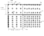
図5には、最終的に合成された矩形状の画像データの右上の角部が図示されている。図5において、実線10aで囲まれた範囲が撮像部4(撮像領域9)の基準となる位置(基準の画素配置になる位置)での撮像範囲を示し、灰色の丸10が、基準位置での撮像における各画素の中心位置を示す。
FIG. 5 shows the upper right corner of the finally synthesized rectangular image data. In FIG. 5, a range surrounded by a
また、二重線11aで囲まれた範囲が基準位置に対して撮像部4をX方向に1/2X方向画素ピッチの奇数倍となる距離だけ移動した場合の撮像範囲を示し、白抜きの三角11が、基準位置に対してX方向に1/2画素ピッチの奇数倍の長さだけずらして撮像した場合の各画素の中心位置を示す。
In addition, the range surrounded by the double line 11a indicates the imaging range when the imaging unit 4 is moved in the X direction by a distance that is an odd multiple of the 1 / 2X direction pixel pitch with respect to the reference position, and the white
また、三重線12aで囲まれた範囲が基準位置に対して撮像部4をY方向に1/2Y方向画素ピッチの奇数倍となる距離だけ移動した場合の撮像範囲を示し、白抜きの丸12が、基準位置に対してY方向に1/2画素ピッチの奇数倍の長さだけずらして撮像した場合の各画素の中心位置を示す。
In addition, the range surrounded by the
また、点線13aで囲まれた範囲が基準位置に対して撮像部4をX方向に1/2X方向画素ピッチの奇数倍となる距離だけ移動し、かつ、Y方向に1/2Y方向画素ピッチの奇数倍となる距離だけ移動した場合の撮像範囲を示し、白抜きのひし形13が、基準位置に対してX方向に1/2画素ピッチの奇数倍の長さをずらし、さらに、Y方向に1/2画素ピッチの奇数倍の長さだけずらして撮像した場合の各画素の中心位置を示す。なお、点線13aで囲まれた範囲では、基準となる画素配置(灰色の丸10)と、X方向にずらした画素配置(白抜き三角11)と、Y方向にずらした画素配置(白抜き丸12)と、X方向およびY方向にずらした画素配置(白抜きのひし形13)とが重なった状態になる。
In addition, the range surrounded by the dotted line 13a moves the imaging unit 4 with respect to the reference position by a distance that is an odd multiple of the 1 / 2X direction pixel pitch in the X direction and has a 1 / 2Y direction pixel pitch in the Y direction. The imaging range when moving by an odd number of distances is shown. The
画素をずらした異なる位置で4回撮像することにより、1回の撮像に比較して画素が4倍(4倍密で)配置されることになり、高解像度とすることが可能になる。すなわち、1/2画像ピッチの奇数倍の長さずらして4回(基準位置の撮像含む)撮像して得られた画像データとしての画像信号が信号処理部7に出力され、信号処理部7で4回分の撮像データを重ね合わせて図5に示す画素配置の画像データを生成してモニタ22等に出力する。
By capturing images four times at different positions where the pixels are shifted, the pixels are arranged four times (four times denser) compared to one imaging, and a high resolution can be achieved. That is, an image signal as image data obtained by imaging four times (including imaging of the reference position) by shifting the length by an odd multiple of 1/2 image pitch is output to the
ここで、空間的な周期をもつ構造の性質である空間周波数に基づいて、上述のように画素をずらして画像を撮像した場合についての効果を説明する。なお、マトリックス状に配置されたセンサにより順次画像を撮像することは、連続信号を一定の間隔をおいて測定することにより、離散信号として収集するサンプリングにあたることになる。 Here, the effect when an image is picked up by shifting the pixels as described above based on the spatial frequency which is the property of the structure having a spatial period will be described. Note that sequentially capturing images with sensors arranged in a matrix means sampling for collecting discrete signals by measuring continuous signals at regular intervals.
図5に示すように、1/2画素ピッチだけ画素をずらした画素の配置を示す位相は、元の撮像部4の撮像素子の画素配置(撮像素子のマトリックス状の各センサの配置)の位相、すなわち、灰色の丸10の配置で示される位相に対して、X方向に1/2画素ピッチずらした白抜き三角11の配置で示される位相と、Y方向に1/2画素ピッチずらした白抜きの丸12の配置で示される位相と、X方向に1/2画素ピッチ、Y方向に1/2画素ピッチずらした白抜きのひし形13の配置で示される位相の3つの位相がある。
As shown in FIG. 5, the phase indicating the pixel arrangement in which the pixels are shifted by ½ pixel pitch is the phase of the pixel arrangement of the original imaging unit 4 (arrangement of each sensor in the matrix of the imaging element). That is, with respect to the phase indicated by the arrangement of the
画素の位置をずらす前のセンサの画素位置(灰色の丸10の配置)の位相を含めると、図5における画素の配置の位相は、すべてで4位相ある。なお、以下の説明において、画素をずらす前の灰色の丸10の配置で示される位相を位相10とし、この位相10に対してX方向に1/2画素ピッチずらした白抜き三角11の配置で示される位相を位相11とし、位相10に対してY方向に1/2画素ピッチずらした白抜きの丸12の配置で示される位相を位相12とし、X方向に1/2画素ピッチ、Y方向に1/2画素ピッチずらした白抜きのひし形13の配置で示される位相を位相13とする。
Including the phase of the pixel position of the sensor (arrangement of gray circles 10) before shifting the pixel position, the phase of the pixel arrangement in FIG. In the following description, the phase indicated by the arrangement of the
この実施形態の撮像では、まず、撮像素子のセンサの画素配置(灰色の丸10で示される画素配置)で撮像する。この時に撮像された画像信号の空間周波数範囲は、図6のaの領域になる。なお、図6は、横軸がサンプリング周波数(fs)で縦軸が基準信号(fl)の周波数である。
なお、ナイキスト定理(標本化定理)では、サンプリング周波数の1/2の周波数(ナイキスト周波数)まで、サンプリング前の原信号(連続信号)を再現できるものとされている。言い換えれば、サンプリング周波数は、サンプリング前の原信号(連続信号)を再現する上では、原信号に含まれる最大周波数の2倍の周波数に設定する必要がある。
In the imaging of this embodiment, first, imaging is performed with the pixel arrangement of the sensor of the imaging element (pixel arrangement indicated by the gray circle 10). The spatial frequency range of the image signal imaged at this time is the region a in FIG. In FIG. 6, the horizontal axis represents the sampling frequency (fs) and the vertical axis represents the frequency of the reference signal (fl).
In the Nyquist theorem (sampling theorem), it is assumed that the original signal (continuous signal) before sampling can be reproduced up to half the sampling frequency (Nyquist frequency). In other words, in order to reproduce the original signal before sampling (continuous signal), it is necessary to set the sampling frequency to a frequency that is twice the maximum frequency included in the original signal.
位相10での撮像後に、上述のように位相10に対してX方向に1/2画素ピッチ、Y方向に1/2画素ピッチずらした位相13の撮像を行い、基準位置での画素位置の撮像画像と、位相13の撮像画像を合成して、1つの画像を合成する。なお、この画像の合成に際しては、位相10の画像に位相13の画像を挿入し、さらに未だ撮像していない位相11で配置される画素の位置と、位相12で配置される画素の位置との値を、その回りの画素(位相10および位相13の画素)の値から周知の内挿(補間)法により生成する。
After imaging at
生成された位相11の画像を合成される画像の位相11の位置に挿入するとともに、生成された位相12の画像を位相12の位置に挿入する。
これにより、X方向、Y方向共に2倍のサンプルを持つ画像を合成できる。この合成した画像信号の空間周波数範囲は、aの領域に、b,cの領域を足した領域となり、空間周波数範囲は広がる。
The generated
Thereby, an image having twice as many samples in both the X direction and the Y direction can be synthesized. The spatial frequency range of the synthesized image signal is a region obtained by adding the regions b and c to the region a, and the spatial frequency range is widened.
次に、位相11の画像を撮像して、上記の合成画像の位相11の画像(内挿で作成した画像)と入れ替える。これにより、空間周波数領域は、さらにdの領域が再現できる範囲となり、さらに空間周波数範囲は広がる。
Next, the
さらに、位相12の撮像を行い、位相12の画像を使って、内挿により生成された位相12の画像を撮像された位相12の画像と入れ替えることにより、同様に画像合成すると、空間周波数領域は、さらにeの領域が再現できる範囲となり、さらに空間周波数範囲は広がる。以上の結果、本発明によれば、被写体の広い範囲の撮像を高精細に撮像できる。
ここで、撮像素子として、1400万画素の撮像素子を使い、1/2画素ピッチだけ各方向に位相をシフトした画像を合成すると、5600万画素相当の撮像素子で撮像した画素が得られる。
Further, when the image of
Here, when an image sensor having 14 million pixels is used as an image sensor and an image whose phase is shifted in each direction by a ½ pixel pitch is synthesized, a pixel imaged by an image sensor equivalent to 56 million pixels is obtained.
また、例えば、上述のように撮像エリア5が撮像部4の撮像素子の撮像領域9の9倍となっていると、上述の4回の撮像を異なる9つの領域で行うことにより、5600万画素の9倍のエリア、すなわち、5億400万画素の画像データが得られることになる。
Further, for example, when the
最終出力の解像度をVGA(640画素×480画素)、最少の倍率を100倍とすると、デジタルズーム処理により、画質劣化なく1300倍程度までの拡大ができる。 If the resolution of the final output is VGA (640 pixels × 480 pixels) and the minimum magnification is 100 times, the digital zoom process can enlarge the image up to about 1300 times without image quality degradation.
このような第2実施形態の顕微鏡システムにおいては、1/2画素ピッチずらした画像データを合成することにより、4倍蜜の画素数で画像データを得られるので、デジタルズームで表示倍率を上げる際に、元の画像データの解像度を高くすることにより、得られる被観察範囲を含む適切な表示倍率の画像データを得た際に、解像度が低くなり過ぎるのを防止できる。 In such a microscope system according to the second embodiment, image data can be obtained with 4 times the number of pixels by synthesizing image data shifted by 1/2 pixel pitch. Therefore, when the display magnification is increased by digital zoom. By increasing the resolution of the original image data, it is possible to prevent the resolution from becoming too low when obtaining image data having an appropriate display magnification including the observed range to be obtained.
たとえば、撮像エリア5の面積を撮像部4の撮像領域9の面積の9倍にし、画素をずらすことにより解像度を4倍にすると、画像データの画素数は、例えば、撮像素子の画素数の約36倍になる。画素数だけで考えれば、画像データの36分の1となる部分を元の画像データと同じ大きさで表示しても、もともとの撮像素子の解像度での画像データの表示になる。
For example, when the area of the
なお、X方向と、Y方向と、X方向にY方向を加えた方向とに、それぞれ1/2画素ピッチだけ画素の配置をずらして上述のように4回撮像した場合には画素が4倍密で配置されるが、例えば、1/3画素ピッチずつ画像の配置をずらして9回撮像してもよく、この場合には画素を9倍密で配置できる。 In addition, when the pixel arrangement is shifted by a ½ pixel pitch in each of the X direction, the Y direction, and the direction in which the Y direction is added to the X direction, the number of pixels is quadrupled as described above. Although the images are arranged densely, for example, images may be captured nine times while shifting the image arrangement by 1/3 pixel pitch. In this case, the pixels can be arranged nine times densely.
この場合、例えば、基準位置での撮像、X方向に1/3X方向画素ピッチずらした撮像、X方向に2/3X方向画素ピッチずらした撮像、Y方向に1/3Y方向画素ピッチずらした撮像、Y方向に2/3Y方向画素ピッチずらした撮像、X方向に1/3X方向画素ピッチずらすとともにY方向に1/3Y方向画素ピッチずらした撮像、X方向に2/3X方向画素ピッチずらすとともにY方向に2/3Y方向画素ピッチずらした撮像、X方向に1/3X方向画素ピッチずらすとともにY方向に2/3Y方向画素ピッチずらした撮像、X方向に2/3X方向画素ピッチずらすとともにY方向に1/3Y方向画素ピッチずらした撮像を行うことになる。
In this case, for example, imaging at the reference position, imaging shifted by 1/3 X direction pixel pitch in the X direction, imaging shifted by 2/3 X direction pixel pitch in the X direction, imaging shifted by 1/3 Y direction pixel pitch in the Y direction, Imaging with 2 / 3Y pixel pitch shifted in Y direction, 1 / 3X pixel pitch shifted in X direction and 1/3 Y pixel pitch shifted in Y direction, 2 / 3X pixel pitch shifted in X direction and
また、同様に1/4画素ピッチずつ画像の配置をずらして16回撮像してもよく、この場合には画素を16倍密で配置できる。 Similarly, the image may be imaged 16 times by shifting the image arrangement by 1/4 pixel pitch. In this case, the pixels can be arranged 16 times denser.
2 被写体
3 レンズ部(光学結像手段)
4 撮像部(撮像手段、撮像装置)
5 撮像エリア
6 X−Y可動部(移動手段)
7 信号処理部(信号処理手段)
9 撮像領域
21 画像処理装置(画像処理手段)
22 モニタ(表示手段)
2
4 Imaging unit (imaging means, imaging device)
5
7 Signal processing part (signal processing means)
9
22 Monitor (display means)
Claims (1)
被写体の画像を表示する表示手段と、
前記被写体の像を撮像エリアに拡大して結像させる光学結像手段と、
画素が縦横に並んだ撮像素子を備え、画像信号を出力する撮像手段と、
前記撮像手段を、前記撮像素子の画像を撮像する撮像領域より広い前記撮像エリア内で、最も短い単位移動距離として、1/2画素に対応する長さより長く、かつ、1/2画素に対応する長さの奇数倍になる長さ単位でX方向とY方向とに移動させる移動手段と、
前記移動手段により移動された前記撮像手段から画像信号として入力する複数箇所で撮像された複数の画像を繋ぎ合わせるように、前記画像信号を処理するとともに、この処理により繋げられた複数の画像からなる結合画像データを生成する信号処理手段と、
前記信号処理手段から出力された前記結合画像データを記憶し、記憶した前記結合画像データを前記表示手段に出力する画像処理手段と、
操作者が操作するとともに操作に基づいた信号を出力する操作手段と、
を備え、
前記画像処理手段は、前記操作手段から出力された信号に基づいて、記憶された前記結合画像データ中の任意の範囲を、任意の拡大倍率で拡大して前記表示手段に出力し、
前記撮像エリアは、前記撮像領域に略対応する大きさの複数の分割領域に分割され、
前記移動手段は、前記撮像領域が各分割領域に順次配置されるように前記撮像手段を移動させるとともに、各分割領域で前記撮像手段をX方向およびY方向にそれぞれ前記単位移動距離だけ移動させ、
前記撮像手段は、各分割領域内の異なる位置毎に撮像を繰り返し、
前記信号処理手段は、各分割領域で複数回撮像された画像を一つに合成するとともに、各分割領域で合成された画像を繋ぎ合わせた画像データを生成して出力することを特徴とする顕微鏡システム。 A microscope system for enlarging and imaging a subject,
Display means for displaying an image of the subject;
Optical imaging means for enlarging and forming an image of the subject in an imaging area;
An image pickup means including an image pickup element in which pixels are arranged in rows and columns and outputting an image signal;
The imaging means is longer than the length corresponding to 1/2 pixel and corresponds to 1/2 pixel as the shortest unit movement distance in the imaging area wider than the imaging area for imaging the image of the imaging element. Moving means for moving in the X direction and the Y direction in units of length that is an odd multiple of the length ;
The image signal is processed so as to connect a plurality of images picked up at a plurality of positions inputted as image signals from the image pickup means moved by the moving means, and a plurality of images connected by this processing are included. Signal processing means for generating combined image data;
Image processing means for storing the combined image data output from the signal processing means, and outputting the stored combined image data to the display means;
Operation means for operating the operator and outputting a signal based on the operation;
With
The image processing means enlarges an arbitrary range in the stored combined image data at an arbitrary magnification based on the signal output from the operation means, and outputs the enlarged range to the display means .
The imaging area is divided into a plurality of divided areas having a size substantially corresponding to the imaging area,
The moving unit moves the imaging unit so that the imaging region is sequentially arranged in each divided region, and moves the imaging unit in each divided region by the unit moving distance in the X direction and the Y direction,
The imaging means repeats imaging at different positions in each divided area,
The signal processing means synthesizes images captured multiple times in each divided region into one, and generates and outputs image data obtained by joining the images synthesized in each divided region. system.
Priority Applications (1)
| Application Number | Priority Date | Filing Date | Title |
|---|---|---|---|
| JP2012129720A JP6068010B2 (en) | 2012-06-07 | 2012-06-07 | Microscope system |
Applications Claiming Priority (1)
| Application Number | Priority Date | Filing Date | Title |
|---|---|---|---|
| JP2012129720A JP6068010B2 (en) | 2012-06-07 | 2012-06-07 | Microscope system |
Publications (2)
| Publication Number | Publication Date |
|---|---|
| JP2013255100A JP2013255100A (en) | 2013-12-19 |
| JP6068010B2 true JP6068010B2 (en) | 2017-01-25 |
Family
ID=49952277
Family Applications (1)
| Application Number | Title | Priority Date | Filing Date |
|---|---|---|---|
| JP2012129720A Expired - Fee Related JP6068010B2 (en) | 2012-06-07 | 2012-06-07 | Microscope system |
Country Status (1)
| Country | Link |
|---|---|
| JP (1) | JP6068010B2 (en) |
Families Citing this family (1)
| Publication number | Priority date | Publication date | Assignee | Title |
|---|---|---|---|---|
| WO2024047884A1 (en) * | 2022-08-29 | 2024-03-07 | 技術開発合同会社 | Electronic magnifier |
Family Cites Families (6)
| Publication number | Priority date | Publication date | Assignee | Title |
|---|---|---|---|---|
| JP2753541B2 (en) * | 1990-02-19 | 1998-05-20 | 株式会社ニコン | Still image pickup device |
| JP4818592B2 (en) * | 2003-07-01 | 2011-11-16 | オリンパス株式会社 | Microscope system, microscope image display system, observation object image display method, and program |
| JP4481178B2 (en) * | 2004-02-13 | 2010-06-16 | パナソニック株式会社 | Imaging method and imaging apparatus |
| JP2007108223A (en) * | 2005-10-11 | 2007-04-26 | Olympus Corp | Microscopic system |
| JP2009033318A (en) * | 2007-07-25 | 2009-02-12 | Nikon Corp | Controller, imaging apparatus, and program |
| JP2010118818A (en) * | 2008-11-12 | 2010-05-27 | Sharp Corp | Image capturing apparatus |
-
2012
- 2012-06-07 JP JP2012129720A patent/JP6068010B2/en not_active Expired - Fee Related
Also Published As
| Publication number | Publication date |
|---|---|
| JP2013255100A (en) | 2013-12-19 |
Similar Documents
| Publication | Publication Date | Title |
|---|---|---|
| JP5555014B2 (en) | Virtual slide creation device | |
| JP2007316258A (en) | Microscope system, microscope image composition method, and program | |
| EP2796918A2 (en) | Image processing apparatus and image processing method | |
| US10613313B2 (en) | Microscopy system, microscopy method, and computer-readable recording medium | |
| CN111788508A (en) | Digital microscope and method for changing the magnification of a digital microscope | |
| KR20110030275A (en) | Method and apparatus for image generation | |
| WO2013100029A9 (en) | Image processing device, image display system, image processing method, and image processing program | |
| US10721413B2 (en) | Microscopy system, microscopy method, and computer readable recording medium | |
| US10429632B2 (en) | Microscopy system, microscopy method, and computer-readable recording medium | |
| JP2006284965A (en) | Microscope device and enlarged image generating method | |
| JP5249799B2 (en) | Image output system, image output method, and image output program | |
| JP2018017969A (en) | Microscope system, information presentation method, and program | |
| JP6068010B2 (en) | Microscope system | |
| JP2010117229A (en) | Height information acquisition apparatus, height information acquisition method, and program | |
| KR100897674B1 (en) | Sample inspection system and sample inspection method | |
| JP5730696B2 (en) | Image processing apparatus and image display system | |
| JP2004012192A (en) | Measuring microscope device, its display method, and its display program | |
| JP2016038542A (en) | Image processing method and image processing apparatus | |
| JP4346888B2 (en) | Microscope equipment | |
| JP2005266718A (en) | Microscopic image photographing system | |
| JP2009042462A (en) | Microscope apparatus, observation method, and observed image processing method | |
| JP2012003216A (en) | Device and method for capturing microscopic image | |
| JPH08201025A (en) | Noncontact coordinate dimension measuring machine | |
| JP4046161B2 (en) | Sample image data processing method and sample inspection system | |
| JP2012150142A (en) | Microscope control apparatus, microscope system and control method thereof |
Legal Events
| Date | Code | Title | Description |
|---|---|---|---|
| A621 | Written request for application examination |
Free format text: JAPANESE INTERMEDIATE CODE: A621 Effective date: 20150529 |
|
| A977 | Report on retrieval |
Free format text: JAPANESE INTERMEDIATE CODE: A971007 Effective date: 20160229 |
|
| A131 | Notification of reasons for refusal |
Free format text: JAPANESE INTERMEDIATE CODE: A131 Effective date: 20160315 |
|
| A521 | Request for written amendment filed |
Free format text: JAPANESE INTERMEDIATE CODE: A523 Effective date: 20160516 |
|
| A131 | Notification of reasons for refusal |
Free format text: JAPANESE INTERMEDIATE CODE: A131 Effective date: 20160621 |
|
| A521 | Request for written amendment filed |
Free format text: JAPANESE INTERMEDIATE CODE: A523 Effective date: 20160818 |
|
| TRDD | Decision of grant or rejection written | ||
| A01 | Written decision to grant a patent or to grant a registration (utility model) |
Free format text: JAPANESE INTERMEDIATE CODE: A01 Effective date: 20161213 |
|
| A61 | First payment of annual fees (during grant procedure) |
Free format text: JAPANESE INTERMEDIATE CODE: A61 Effective date: 20161222 |
|
| R150 | Certificate of patent or registration of utility model |
Ref document number: 6068010 Country of ref document: JP Free format text: JAPANESE INTERMEDIATE CODE: R150 |
|
| S111 | Request for change of ownership or part of ownership |
Free format text: JAPANESE INTERMEDIATE CODE: R313111 |
|
| R350 | Written notification of registration of transfer |
Free format text: JAPANESE INTERMEDIATE CODE: R350 |
|
| R250 | Receipt of annual fees |
Free format text: JAPANESE INTERMEDIATE CODE: R250 |
|
| LAPS | Cancellation because of no payment of annual fees |