JP2011256575A - Composite beam structure - Google Patents

Composite beam structure Download PDF

Info

Publication number
JP2011256575A
JP2011256575A JP2010131053A JP2010131053A JP2011256575A JP 2011256575 A JP2011256575 A JP 2011256575A JP 2010131053 A JP2010131053 A JP 2010131053A JP 2010131053 A JP2010131053 A JP 2010131053A JP 2011256575 A JP2011256575 A JP 2011256575A
Authority
JP
Japan
Prior art keywords
composite beam
steel
composite
steel wire
sheath tube
Prior art date
Legal status (The legal status is an assumption and is not a legal conclusion. Google has not performed a legal analysis and makes no representation as to the accuracy of the status listed.)
Granted
Application number
JP2010131053A
Other languages
Japanese (ja)
Other versions
JP5613465B2 (en
Inventor
Yuji Ishikawa
裕次 石川
Yasumasa Miyauchi
靖昌 宮内
Hiroyuki Ueda
博之 上田
Takaaki Hiroshige
隆明 廣重
Current Assignee (The listed assignees may be inaccurate. Google has not performed a legal analysis and makes no representation or warranty as to the accuracy of the list.)
Takenaka Komuten Co Ltd
Original Assignee
Takenaka Komuten Co Ltd
Priority date (The priority date is an assumption and is not a legal conclusion. Google has not performed a legal analysis and makes no representation as to the accuracy of the date listed.)
Filing date
Publication date
Application filed by Takenaka Komuten Co Ltd filed Critical Takenaka Komuten Co Ltd
Priority to JP2010131053A priority Critical patent/JP5613465B2/en
Publication of JP2011256575A publication Critical patent/JP2011256575A/en
Application granted granted Critical
Publication of JP5613465B2 publication Critical patent/JP5613465B2/en
Expired - Fee Related legal-status Critical Current
Anticipated expiration legal-status Critical

Links

Images

Landscapes

  • Rod-Shaped Construction Members (AREA)

Abstract

PROBLEM TO BE SOLVED: To provide a composite beam structure capable of resisting the vertical load of a long-span structure.SOLUTION: A composite beam 14 has: a reinforced-concrete beam member 15; beam steel frames 28 joined to junctions 40 embedded in both ends of the beam member 15 and provided on pillars 12, respectively; and PC steel wires 34 provided from one end of the beam member 15 to the other end thereof and introducing compressive force to the beam member 15. Because the beam steel frames 28 are embedded in the both ends of the beam member 15 respectively and thus the beam steel frames 28 and the beam member 15 are joined together, then the PC steel wires require no prestress force for joining the beam member 15 and the beam steel frames 28 together and the prestress force can be freely set. Therefore, even if the required span of the composite beam 14 becomes longer, the prestress force required for the beam member 15 can be introduced by the PC steel wires 34 and the composite beam 14 can resist the vertical load of a long-span structure.

Description

本発明は、合成梁構造に関する。   The present invention relates to a composite beam structure.

従来、柱に接合される鉄骨造の梁端部と鉄筋コンクリート造の梁中央部とを有し、梁端部の端面と梁中央部の端面とを圧着接合した合成梁構造がある(例えば、特許文献1参照)。   2. Description of the Related Art Conventionally, there is a composite beam structure that has a steel beam end part and a reinforced concrete beam center part that are joined to a column, and is bonded to the end face of the beam end part and the end face of the beam center part (for example, a patent) Reference 1).

特許文献1の合成梁構造は、梁端部を鉄骨造とし、梁中央部をPC鋼材を用いたPRC造とすると共に、PC鋼材により付与されたプレストレス力(圧縮力)で梁端部の鉄骨部材と梁中央部のPRC部材とを接合している。   In the composite beam structure of Patent Document 1, the beam end is made of steel and the center of the beam is made of PRC using PC steel, and the prestress force (compressive force) applied by the PC steel is used for the beam end. The steel member and the PRC member at the center of the beam are joined.

しかし、特許文献1の合成梁構造は、PC鋼材により付与されるプレストレス力が鉄骨部材とPRC部材の接合に使われるため、長大スパン(例えば12m以上の幅)の構造物に適用した場合に、PC鋼材により付与されるプレストレス力が不十分となり、鉛直荷重に耐えることが困難であった。   However, the composite beam structure of Patent Document 1 is applied to a structure having a long span (for example, a width of 12 m or more) because the prestressing force applied by the PC steel material is used for joining the steel member and the PRC member. The prestressing force imparted by the PC steel material is insufficient, and it is difficult to withstand the vertical load.

特開2007−211507JP 2007-2111507

本発明は、長大スパン構造物の鉛直荷重に耐えることができる合成梁構造を得ることを目的とする。   An object of this invention is to obtain the composite beam structure which can endure the vertical load of a long span structure.

本発明の請求項1に係る合成梁構造は、鉄筋コンクリート造の梁部材と、前記梁部材の両端部に埋設され露出した露出部が、柱に設けられた接合部に接合される鉄骨部材と、前記梁部材に圧縮力を導入するプレストレス部材と、を有する。   The composite beam structure according to claim 1 of the present invention is a reinforced concrete beam member, and a steel member in which exposed portions embedded and exposed at both ends of the beam member are joined to a joint provided on a column, A prestressing member that introduces a compressive force into the beam member.

上記構成によれば、鉄筋コンクリート造の梁部材の両端部に鉄骨部材が埋設されることにより、鉄骨部材が梁部材と接合される。ここで、梁部材に設けられるプレストレス部材は、梁部材と鉄骨部材の接合にプレストレス力を必要とされないため、プレストレス力を自由に設定できる。   According to the said structure, a steel frame member is joined to a beam member by embedding a steel frame member in the both ends of the beam member of a reinforced concrete structure. Here, since the prestress member provided in the beam member does not require a prestressing force for joining the beam member and the steel member, the prestressing force can be set freely.

これにより、合成梁の必要とされるスパンが長くなっても、プレストレス部材によって梁部材に必要なプレストレス力を導入することができ、合成梁が長大スパン構造物の鉛直荷重に耐えることができる。また、梁部材の両端部のみに鉄骨部材が用いられているので、合成梁全体を鉄骨部材で構成したものに較べて鉄骨量を減らすことができ、低コスト化が可能となる。   As a result, even if the span required for the composite beam becomes long, the prestressing force required for the beam member can be introduced by the prestress member, and the composite beam can withstand the vertical load of the long span structure. it can. In addition, since the steel member is used only at both ends of the beam member, the amount of steel frame can be reduced as compared with a case where the entire composite beam is formed of the steel member, and the cost can be reduced.

本発明の請求項2に係る合成梁構造は、前記プレストレス部材は、前記梁部材に配置されたシース管へ挿通されたPC鋼線であり、前記PC鋼線には施工現場で引張力が導入され、前記シース管にグラウトを注入しない。   In the composite beam structure according to claim 2 of the present invention, the prestress member is a PC steel wire inserted into a sheath tube disposed in the beam member, and the PC steel wire has a tensile force at a construction site. Introduced and does not inject grout into the sheath tube.

上記構成によれば、シース管に挿通されたPC鋼線に施工現場で引張力が導入される。ここで、シース管にはグラウトが注入されず、PC鋼線がアンボンド状態となっているので、定着を緩めるだけでシース管からPC鋼線を取り除くことができる。これにより、PC鋼線を取り除いて梁部材を交換することが容易となり、異なる長さの梁部材を配置して合成梁の長さ調整が容易となる。   According to the said structure, tensile force is introduce | transduced in the construction site to the PC steel wire penetrated by the sheath pipe | tube. Here, since the grout is not injected into the sheath tube and the PC steel wire is in an unbonded state, the PC steel wire can be removed from the sheath tube simply by loosening the fixing. Thereby, it becomes easy to remove the PC steel wire and replace the beam member, and it is easy to adjust the length of the composite beam by arranging the beam members having different lengths.

本発明の請求項3に係る合成梁構造は、前記プレストレス部材は、前記梁部材に配置されたシース管へ挿通されたPC鋼線であり、前記PC鋼線には施工現場で引張力が導入され、前記シース管にグラウトが注入される。この構成によれば、シース管に挿通したPC鋼線に施工現場で引張力を導入後、シース管にグラウトを注入することでPC鋼線が固定されるので、プレストレス部材の固定が容易となる。   In the composite beam structure according to claim 3 of the present invention, the pre-stress member is a PC steel wire inserted into a sheath tube disposed in the beam member, and the PC steel wire has a tensile force at a construction site. The grout is injected into the sheath tube. According to this configuration, the PC steel wire is fixed by injecting the grout into the sheath tube after introducing tensile force to the PC steel wire inserted through the sheath tube at the construction site. Become.

本発明の請求項4に係る合成梁構造は、前記梁部材には複数のせん断補強筋が設けられ、該複数のせん断補強筋の配置間隔が、前記梁部材の中央部よりも両端部で狭くなっている。この構成によれば、鉄骨部材の端部で梁部材に作用するてこ反力の一部が、梁の中央部よりも狭い間隔で配置された両端部のせん断補強筋で負担されるため、梁の鉛直荷重に対する耐性が向上する。   In the composite beam structure according to claim 4 of the present invention, the beam member is provided with a plurality of shear reinforcement bars, and the arrangement interval of the plurality of shear reinforcement bars is narrower at both ends than the center part of the beam member. It has become. According to this configuration, a part of the lever reaction force acting on the beam member at the end of the steel member is borne by the shear reinforcement bars at both ends arranged at a smaller interval than the center of the beam. The resistance to vertical load is improved.

本発明は、上記構成としたので、長大スパン構造物の鉛直荷重に耐えることができる。   Since this invention was set as the said structure, it can endure the vertical load of a long span structure.

本発明の第1実施形態に係る合成梁を有する建物の全体図である。It is a general view of the building which has a composite beam concerning a 1st embodiment of the present invention. 本発明の第1実施形態に係る合成梁の構造を示す説明図である。It is explanatory drawing which shows the structure of the composite beam which concerns on 1st Embodiment of this invention. (a)本発明の第1実施形態に係る合成梁の図1のA−A’における断面図である。(b)本発明の第1実施形態に係る合成梁の図1のB−B’における断面図である。(A) It is sectional drawing in A-A 'of FIG. 1 of the composite beam which concerns on 1st Embodiment of this invention. (B) It is sectional drawing in B-B 'of FIG. 1 of the composite beam which concerns on 1st Embodiment of this invention. (a)本発明の第1実施形態に係る合成梁の図3のC−C’における断面図である。(b)本発明の第1実施形態に係る合成梁の他の実施例を示す断面図である。(A) It is sectional drawing in C-C 'of FIG. 3 of the composite beam which concerns on 1st Embodiment of this invention. (B) It is sectional drawing which shows the other Example of the composite beam which concerns on 1st Embodiment of this invention. 本発明の第1実施形態に係る合成梁を有する建物の施工状態を示す説明図である。It is explanatory drawing which shows the construction state of the building which has the composite beam which concerns on 1st Embodiment of this invention. (a)本発明の第1実施形態に係る合成梁の模式図である。(b)本発明の第1実施形態に係る合成梁のモーメント図である。(c)本発明の第1実施形態に係る合成梁のせん断力図である。(d)本発明の第1実施形態に係る合成梁の鉛直荷重及びてこ反力の作用位置を示す模式図である。(A) It is a schematic diagram of the composite beam which concerns on 1st Embodiment of this invention. (B) It is a moment figure of the composite beam which concerns on 1st Embodiment of this invention. (C) It is a shear-force figure of the composite beam which concerns on 1st Embodiment of this invention. (D) It is a schematic diagram which shows the action position of the vertical load and leverage reaction force of the composite beam which concerns on 1st Embodiment of this invention. 本発明の第2実施形態に係る合成梁の構造を示す説明図である。It is explanatory drawing which shows the structure of the composite beam which concerns on 2nd Embodiment of this invention. (a)本発明の第2実施形態に係る合成梁の図7のD−D’における断面図である。(b)本発明の第2実施形態に係る合成梁の図1のE−E’における断面図である。(A) It is sectional drawing in D-D 'of FIG. 7 of the composite beam which concerns on 2nd Embodiment of this invention. (B) It is sectional drawing in E-E 'of FIG. 1 of the composite beam which concerns on 2nd Embodiment of this invention. (a)〜(c)本発明の第2実施形態に係る合成梁の一部のプレキャスト部材を交換する手順を示す工程図である。(A)-(c) It is process drawing which shows the procedure of replacing | exchanging some precast members of the composite beam which concerns on 2nd Embodiment of this invention. 本発明の第1実施形態の他の実施例に係る合成梁の部分断面図である。It is a fragmentary sectional view of the composite beam which concerns on the other Example of 1st Embodiment of this invention.

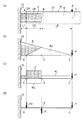
本発明の合成梁構造の第1実施形態を図面に基づき説明する。図1には、地盤20上に構築された構造物としての建物10の1、2階層が示されている。建物10は、地盤20上に立設された複数の柱12と、柱12に架設された複数の合成梁14とで構成されている。なお、合成梁14には小梁が架設されると共にコンクリート打設によりスラブが形成されているが、これらの図示を省略している。また、図1では、柱12及び合成梁14を正面視にて透視した状態での各部材の配置が示されている。   1st Embodiment of the composite beam structure of this invention is described based on drawing. FIG. 1 shows the first and second floors of a building 10 as a structure constructed on the ground 20. The building 10 includes a plurality of columns 12 standing on the ground 20 and a plurality of composite beams 14 installed on the columns 12. In addition, although the small beam is constructed in the composite beam 14, and the slab is formed by concrete placement, these are abbreviate | omitting illustration. Further, FIG. 1 shows the arrangement of each member in a state where the column 12 and the composite beam 14 are seen through in front view.

図2に示すように、柱12は、軸方向(矢印Z方向:鉛直方向)に沿って配設された複数の柱主筋16と、柱主筋16に対して垂直方向に柱主筋16を囲んで複数配置され柱主筋16に緊結された帯筋18と、柱12の仕口部で略水平に配置されると共に大半が柱12に内包され、一方の端部が柱12の側面から外側へ突出したH形鋼からなる柱鉄骨22とを有している。   As shown in FIG. 2, the column 12 surrounds the column main bars 16 in a direction perpendicular to the column main bars 16 and a plurality of column main bars 16 disposed along the axial direction (arrow Z direction: vertical direction). A plurality of strips 18 that are arranged and fastened to the column main bars 16 are arranged substantially horizontally at the joints of the columns 12, most of which are included in the columns 12, and one end portion projects outward from the side surface of the columns 12. And a column steel frame 22 made of H-shaped steel.

柱鉄骨22の柱12の側面から外側へ突出した部位は、合成梁14が接合される接合部40を構成しており、柱鉄骨22の接合部40のウェブには、鉛直方向に並んだ複数の貫通孔23(図5参照)が形成されている。   The portion of the column steel frame 22 that protrudes outward from the side surface of the column 12 constitutes a joint 40 to which the composite beam 14 is joined. The web of the joint 40 of the column steel frame 22 is arranged in a plurality in the vertical direction. Through-holes 23 (see FIG. 5) are formed.

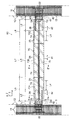
一方、合成梁14は、梁主筋24及びせん断補強筋としてのあばら筋26が設けられ、コンクリート打設により直方体状に形成された梁部材15を有している。梁部材15には、さらに、鉄骨部材としての梁鉄骨28と、シース管32と、プレストレス部材としてのPC鋼線34と、定着具36とが設けられている。   On the other hand, the composite beam 14 is provided with a beam main bar 24 and a rib bar 26 as a shear reinforcement bar, and has a beam member 15 formed in a rectangular parallelepiped shape by concrete placement. The beam member 15 is further provided with a beam steel frame 28 as a steel frame member, a sheath tube 32, a PC steel wire 34 as a prestress member, and a fixing tool 36.

ここで、合成梁14の左端面15Aと柱12との間隔、及び右端面15Bと柱12との間隔はL1となっている。また、合成梁14は、軸方向(矢印X方向:水平方向)において、長さL2の左端部14A、長さL3の中央部14B、及び長さL2の右端部14Cで区分されており、左端部14A及び右端部14Cに梁鉄骨28の一部が埋設されている。   Here, the interval between the left end surface 15A of the composite beam 14 and the column 12 and the interval between the right end surface 15B and the column 12 are L1. The composite beam 14 is divided in the axial direction (arrow X direction: horizontal direction) by a left end portion 14A having a length L2, a central portion 14B having a length L3, and a right end portion 14C having a length L2. Part of the beam steel frame 28 is embedded in the portion 14A and the right end portion 14C.

梁主筋24は、合成梁14の軸方向に沿って延伸した異形鉄筋であり、合成梁14の幅方向(図2の奥行き方向)及び鉛直方向に間隔を空けて複数(本実施形態では4本)配設されている。また梁主筋24は、両端部がU字状に曲げられた形状となっている。なお、合成梁14の梁主筋としては、両端部がU字形状の梁主筋24に限らず、例えば、図10(a)に示すように、瘤(こぶ)状部25Aが両端部に形成された梁主筋25を用いてもよく、あるいは、図10(b)に示すように、ナットや鍔(つば)部材等の金具27Aが螺合又は溶接により両端部に取り付けられた梁主筋27を用いてもよい。つまり、主筋の外径より大径で、アンカー効果が期待できるものであればよい。   The beam main reinforcing bars 24 are deformed reinforcing bars extending along the axial direction of the composite beam 14, and a plurality (four in this embodiment) are spaced apart in the width direction (depth direction in FIG. 2) and the vertical direction of the composite beam 14. ) Is arranged. Further, the beam main bar 24 has a shape in which both ends are bent in a U-shape. Note that the beam main reinforcement of the composite beam 14 is not limited to the beam main reinforcement 24 having both ends at the U-shape, and for example, as shown in FIG. Alternatively, the main beam bar 25 may be used, or as shown in FIG. 10B, a main beam beam 27 in which a metal fitting 27A such as a nut or a collar member is attached to both ends by screwing or welding is used. May be. That is, it is sufficient if the diameter is larger than the outer diameter of the main muscle and the anchor effect can be expected.

図2に示すように、あばら筋26は、梁主筋24に対して垂直となる方向に配置された異形鉄筋からなるせん断補強筋であり、全ての梁主筋24を四角形状に取り囲むと共に合成梁14の軸方向に間隔を空けて複数配置されている。ここで、合成梁14の左端部14A及び右端部14Cにおけるあばら筋26の間隔d2は、中央部14Bにおけるあばら筋26の間隔d1よりも小さくなっている。   As shown in FIG. 2, the stirrups 26 are shear reinforcing bars made of deformed reinforcing bars arranged in a direction perpendicular to the beam main bars 24, surround all the beam main bars 24 in a square shape, and combine with the composite beam 14. A plurality of them are arranged at intervals in the axial direction. Here, the spacing d2 of the stirrups 26 at the left end 14A and the right end 14C of the composite beam 14 is smaller than the spacing d1 of the stirrups 26 at the central portion 14B.

また、合成梁14の中央部14Bでは、両端からそれぞれ内側へ向けて距離L4の範囲のみ、あばら筋26の間隔がd2となっている。あばら筋26は、梁主筋24に緊結されている。なお、各図面における梁主筋24及びあばら筋26の表示は、異形鉄筋としての表示を省略して丸鋼として表示している。   In the central portion 14B of the composite beam 14, the spacing between the streaks 26 is d2 only in the range of the distance L4 from both ends toward the inside. The stirrup 26 is tightly coupled to the beam main bar 24. In addition, the display of the beam main reinforcement 24 and the stirrup reinforcement 26 in each drawing is omitted as a deformed reinforcing bar, and is displayed as a round steel bar.

梁鉄骨28は、合成梁14の左端部14Aと右端部14Cに一つずつ設けられており、大半の部位が左端部14A又は右端部14Cに埋設され、残りの部位が柱12と対向する梁部材15の左端面15A又は右端面15Bから外側へ露出した配置となっている。   One beam steel frame 28 is provided at each of the left end portion 14A and the right end portion 14C of the composite beam 14, most of the portions are embedded in the left end portion 14A or the right end portion 14C, and the remaining portions are beams facing the column 12. The arrangement is such that the member 15 is exposed to the outside from the left end surface 15A or the right end surface 15B.

また、図3(a)に示すように、梁鉄骨28はH形鋼であり、合成梁14の幅方向(矢印Y方向)を面外方向として合成梁14の断面中央に立設された板状のウェブ28Aと、ウェブ28Aの上端で合成梁14の幅方向両側に突出した上側フランジ28Bと、ウェブ28Aの下端で合成梁14の幅方向両側に突出した下側フランジ28Cとを有している。上側フランジ28B及び下側フランジ28Cは、上側フランジ28Bの上面から上方に向けて、又は下側フランジ28Cの下面から下方に向けて、それぞれ複数のスタッド38が突設されている。なお、梁鉄骨28は、上側フランジ28B及び下側フランジ28Cにスタッド38を設けたものに限定されず、スタッド38が無いものであってもよい。   Further, as shown in FIG. 3A, the beam steel frame 28 is H-shaped steel, and is a plate erected at the center of the cross section of the composite beam 14 with the width direction (arrow Y direction) of the composite beam 14 being the out-of-plane direction. A web-shaped web 28A, an upper flange 28B projecting on both sides in the width direction of the composite beam 14 at the upper end of the web 28A, and a lower flange 28C projecting on both sides in the width direction of the composite beam 14 at the lower end of the web 28A. Yes. The upper flange 28B and the lower flange 28C are each provided with a plurality of studs 38 protruding upward from the upper surface of the upper flange 28B or downward from the lower surface of the lower flange 28C. In addition, the beam steel frame 28 is not limited to what provided the stud 38 in the upper side flange 28B and the lower side flange 28C, The thing without the stud 38 may be sufficient.

図4(a)に示すように、梁部材15の各端面15A、15Bからそれぞれ外側へ露出した梁鉄骨28の露出部28Dには、鉛直方向に並んだ複数の貫通孔29が形成されている。ここで、図2に示すように、柱鉄骨22の接合部40と梁鉄骨28の露出部28Dとを合わせた状態で、柱鉄骨22のウェブ22Aと梁鉄骨28のウェブ28A(図3(a)参照)とに跨って接合用のプレート部材42が配置されており、プレート部材42に形成された貫通孔(図示省略)と柱鉄骨22の貫通孔23(図5参照)、及びプレート部材42に形成された貫通孔と梁鉄骨28の貫通孔29を連通させた状態でボルト44を締結することで、柱鉄骨22に合成梁14が接合されている。   As shown in FIG. 4 (a), a plurality of through holes 29 arranged in the vertical direction are formed in the exposed portion 28D of the beam steel frame 28 exposed outward from the end faces 15A and 15B of the beam member 15, respectively. . Here, as shown in FIG. 2, in a state where the joint 40 of the column steel 22 and the exposed portion 28D of the beam steel 28 are combined, the web 22A of the column steel 22 and the web 28A of the beam steel 28 (FIG. 3A ) (See FIG. 5), the plate member 42 for joining is disposed, the through hole (not shown) formed in the plate member 42, the through hole 23 (see FIG. 5) of the column steel frame 22, and the plate member 42. The composite beam 14 is joined to the column steel frame 22 by fastening the bolts 44 in a state where the through-holes formed in the through hole and the through-holes 29 of the beam steel frame 28 are in communication with each other.

図3(a)には、図2の合成梁14の左端部14AをA−A’で切ったときの断面図が示されており、図3(b)には、図2の合成梁14の中央部14BをB−B’で切ったときの断面図が示されている。なお、合成梁14の左端部14Aと右端部14Cの構成は同様であるため、ここでは左端部14Aについて説明し、右端部14Cの説明を省略する。   3A shows a cross-sectional view when the left end portion 14A of the composite beam 14 of FIG. 2 is cut along AA ′, and FIG. 3B shows the composite beam 14 of FIG. Sectional drawing when the center part 14B of this is cut by BB 'is shown. Since the left end portion 14A and the right end portion 14C of the composite beam 14 have the same configuration, only the left end portion 14A will be described here, and the description of the right end portion 14C will be omitted.

図3(a)に示すように、合成梁14の左端部14Aでは、梁部材15のコンクリートで覆われた梁鉄骨28のウェブ28Aの両側にシース管32(32A、32B)が埋設されている。シース管32A内及びシース管32B内には、それぞれPC鋼線34(34A、34B)が挿通されており、PC鋼線34には、プレストレス力(圧縮力)が作用している。なお、左端部14Aの断面におけるシース管32の埋設位置は、合成梁14の梁せい方向(矢印Z方向)の略中央となっている。   As shown in FIG. 3A, at the left end portion 14A of the composite beam 14, sheath tubes 32 (32A and 32B) are embedded on both sides of the web 28A of the beam steel frame 28 covered with the concrete of the beam member 15. . PC steel wires 34 (34A, 34B) are respectively inserted into the sheath tube 32A and the sheath tube 32B, and a prestressing force (compression force) acts on the PC steel wire 34. The embedded position of the sheath tube 32 in the cross section of the left end portion 14A is substantially the center of the beam direction of the composite beam 14 (arrow Z direction).

図3(b)に示すように、合成梁14の中央部14Bでは、梁鉄骨28が無く、梁主筋24、あばら筋26、シース管32、及びPC鋼線34だけが設けられた構成となっている。また、中央部14Bでは、断面におけるシース管32の埋設位置が、合成梁14の梁せい方向(矢印Z方向)の下端側となっている。   As shown in FIG. 3B, the central portion 14B of the composite beam 14 has no beam steel frame 28, and only the beam main bar 24, the stirrup 26, the sheath tube 32, and the PC steel wire 34 are provided. ing. Further, in the central portion 14B, the embedded position of the sheath tube 32 in the cross section is the lower end side in the beam crushing direction (arrow Z direction) of the composite beam 14.

図4(a)には、合成梁14を図3(a)、(b)のC−C’で切ったときの断面図が示されている。合成梁14において、シース管32及びPC鋼線34は、全体が下側に凸となるように偏心して曲線配置されている。   FIG. 4A shows a cross-sectional view of the composite beam 14 taken along C-C ′ in FIGS. 3A and 3B. In the composite beam 14, the sheath tube 32 and the PC steel wire 34 are eccentrically arranged so as to be convex downward.

ここで、シース管32は、梁部材15の左端面15Aでウェブ28Aの両側に形成された凹部35Aから、梁部材15の右端面15Bでウェブ28Aの両側に形成された凹部35Bまで埋設されている。   Here, the sheath tube 32 is embedded from the recesses 35A formed on both sides of the web 28A on the left end surface 15A of the beam member 15 to the recesses 35B formed on both sides of the web 28A on the right end surface 15B of the beam member 15. Yes.

一方、PC鋼線34は、シース管32内に挿通されると共に両端部が凹部35A、35B内にそれぞれ突出されており、即ち合成梁14の一方端から他方端まで設けられている。また、PC鋼線34の両端部は、凹部35A、35B内でそれぞれ定着具36によって固定(定着)され、梁部材15に圧縮力を導入している。なお、定着具36は、凹部35A、35B内に配置された支圧板及び雌コーンと、図示しないジャッキで引っ張られたPC鋼線34に外挿されるクサビ状の雄コーンとで構成されており、PC鋼線34の引張力を解除することで雄コーンが雌コーンと接触して固定されるクサビ方式のものを用いている。   On the other hand, the PC steel wire 34 is inserted into the sheath tube 32 and both end portions thereof protrude into the recesses 35A and 35B, that is, provided from one end to the other end of the composite beam 14. Further, both ends of the PC steel wire 34 are fixed (fixed) by the fixing tool 36 in the recesses 35 </ b> A and 35 </ b> B, respectively, and a compressive force is introduced to the beam member 15. The fixing device 36 is composed of a pressure bearing plate and a female cone disposed in the recesses 35A and 35B, and a wedge-shaped male cone extrapolated to a PC steel wire 34 pulled by a jack (not shown). The wedge type is used in which the male cone is fixed in contact with the female cone by releasing the tensile force of the PC steel wire 34.

次に、合成梁14及び建物10の施工手順について説明する。   Next, the construction procedure of the composite beam 14 and the building 10 will be described.

図2、図3(a)、(b)、及び図4(a)に示すように、まず、合成梁14に合わせて形成された型枠(図示省略)内に梁主筋24(図2参照)及びあばら筋26を配置し、梁主筋24にあばら筋26を緊結する。そして、梁鉄骨28を露出部28Dが露出するように型枠の両端にそれぞれ配置し、型枠内で梁鉄骨28のウェブ28Aの両側に下側に凸となるようにシース管32を配置する。このとき、シース管32の両端部には凹部35A、35Bを形成するための型枠を配置する。   As shown in FIGS. 2, 3 (a), 3 (b), and 4 (a), first, a beam main bar 24 (see FIG. 2) in a mold (not shown) formed in accordance with the composite beam 14. ) And the stirrup 26, and the stirrup 26 is tightly coupled to the main beam 24. The beam steel frames 28 are arranged at both ends of the mold so that the exposed portions 28D are exposed, and the sheath tube 32 is arranged so as to protrude downward on both sides of the web 28A of the beam steel frames 28 within the mold. . At this time, molds for forming the recesses 35 </ b> A and 35 </ b> B are disposed at both ends of the sheath tube 32.

続いて、型枠内にコンクリートを打設し所定の期間養生してから型枠を取り外すことにより梁部材15が形成される。そして、梁部材15のシース管32内にPC鋼線34を挿通する。挿通したPC鋼線34の両端部には、凹部35A、35B内において定着具36の支圧板及び雌コーンを配置する。   Subsequently, the concrete is placed in the mold and cured for a predetermined period, and then the mold is removed to form the beam member 15. Then, the PC steel wire 34 is inserted into the sheath tube 32 of the beam member 15. At both ends of the inserted PC steel wire 34, a bearing plate and a female cone of the fixing tool 36 are disposed in the recesses 35A and 35B.

続いて、施工現場にてPC鋼線34の両端部を図示しないジャッキを用いて引っ張り、PC鋼線34に所定の引張力を導入すると共にPC鋼線34に定着具36の雄コーンを外挿した後、ジャッキを取り外す。このとき、PC鋼線34が元の状態に縮もうとする復元力によって定着具36の雄コーンが移動し、雌コーンと接触して、PC鋼線34の両端部が凹部35A、35B内に固定される。そして、シース管32内にグラウトを充填して硬化させる。このようにして、合成梁14が形成される。   Subsequently, both ends of the PC steel wire 34 are pulled using a jack (not shown) at the construction site, a predetermined tensile force is introduced into the PC steel wire 34, and the male cone of the fixing tool 36 is extrapolated to the PC steel wire 34. After that, remove the jack. At this time, the male cone of the fixing tool 36 is moved by the restoring force of the PC steel wire 34 to shrink to the original state, and comes into contact with the female cone, so that both ends of the PC steel wire 34 are in the recesses 35A and 35B. Fixed. The sheath tube 32 is filled with grout and cured. In this way, the composite beam 14 is formed.

一方、図5に示すように、柱主筋16、帯筋18、及び柱鉄骨22を図示しない型枠内に配設した状態でコンクリートを打設することにより、地盤20上に複数の柱12を立設する。なお、ここでは例として、3本の柱12が立設され8箇所の接合部40が設けられている場合について説明するが、これに限らず、柱12及び接合部40の数は適宜選択されるものである。   On the other hand, as shown in FIG. 5, by placing concrete in a state where the column main reinforcement 16, the band reinforcement 18, and the column steel frame 22 are arranged in a mold not shown, a plurality of columns 12 are formed on the ground 20. Stand up. Here, as an example, a case where three pillars 12 are erected and eight joints 40 are provided will be described. However, the present invention is not limited thereto, and the number of pillars 12 and joints 40 is appropriately selected. Is.

続いて、柱12の立設後、合成梁14の上面にワイヤーWを取り付けると共にクレーン(図示省略)で吊り下げ、1階左側の1組の接合部40の間に合成梁14を配置する。そして、柱鉄骨22の接合部40と梁鉄骨28の露出部28Dの位置を合わせた状態で、柱鉄骨22のウェブ22Aと梁鉄骨28のウェブ28Aとに跨ってプレート部材42を配置し、ボルト44で締結する。これにより、柱12へ合成梁14が接合される。   Subsequently, after the pillar 12 is erected, the wire W is attached to the upper surface of the composite beam 14 and suspended by a crane (not shown), and the composite beam 14 is disposed between the pair of joint portions 40 on the left side of the first floor. Then, in a state where the positions of the joint portion 40 of the column steel 22 and the exposed portion 28D of the beam steel frame 28 are aligned, the plate member 42 is disposed across the web 22A of the column steel frame 22 and the web 28A of the beam steel frame 28, and bolts Fasten at 44. Thereby, the composite beam 14 is joined to the column 12.

同様にして、2階左側の接合部40、1階右側の接合部40、及び2階右側の接合部40に順次合成梁14を接合することで、柱12への複数の合成梁14の接合が完了する。そして、合成梁14の接合が完了した後、小梁(図示省略)を配設し、型枠を配置してコンクリート打設することによりスラブ(図示省略)を形成する。このようにして、建物10が構築される。   Similarly, a plurality of composite beams 14 are joined to the column 12 by sequentially joining the composite beams 14 to the second floor left joint 40, the first floor right joint 40, and the second floor right joint 40. Is completed. Then, after the joining of the composite beam 14 is completed, a small beam (not shown) is arranged, and a slab (not shown) is formed by placing a formwork and placing concrete. In this way, the building 10 is constructed.

次に、本発明の第1実施形態の作用について説明する。   Next, the operation of the first embodiment of the present invention will be described.

図2に示すように、梁部材15の両端部に梁鉄骨28が埋設されることにより、梁鉄骨28が梁部材15と接合される。ここで、梁部材15に設けられるPC鋼線34は、梁部材15と梁鉄骨28の接合にプレストレス力(圧縮力)が必要とされないため、プレストレス力を自由に設定できる。   As shown in FIG. 2, the beam steel frame 28 is joined to the beam member 15 by embedding the beam steel frame 28 at both ends of the beam member 15. Here, since the prestressing force (compression force) is not required for joining the beam member 15 and the beam steel frame 28, the PC steel wire 34 provided in the beam member 15 can freely set the prestressing force.

これにより、合成梁14の必要とされるスパンが長くなっても、PC鋼線34によって梁部材15に必要な圧縮力を導入することができ、合成梁14が、長大スパン構造物の鉛直荷重に耐えることができる。また、合成梁14の左端部14A及び右端部14Cのみに梁鉄骨28が用いられているので、合成梁14全体を鉄骨部材で構成したものに較べて鉄骨量を減らすことができ、低コスト化が可能となる。   Thereby, even if the span required for the composite beam 14 becomes long, the necessary compressive force can be introduced to the beam member 15 by the PC steel wire 34, and the composite beam 14 can be applied to the vertical load of the long span structure. Can withstand. Further, since the beam steel frame 28 is used only at the left end portion 14A and the right end portion 14C of the composite beam 14, the amount of the steel frame can be reduced and the cost can be reduced as compared with a case where the entire composite beam 14 is configured by a steel member. Is possible.

ここで、図6(a)〜(d)を用いて、合成梁14に作用する応力伝達状態について説明する。図6(a)には、柱12に接合された合成梁14の中央から左半分が模式図で示されている。なお、合成梁14の中央から右半分については同様のため説明を省略する。柱12の側面から梁部材15の左端面15Aまでの距離L1の領域では、鉄骨部材のみで構成されているため、この領域を鉄骨部Tとする。また、梁部材15の左端面15Aから梁部材15に埋設された梁鉄骨28の右端面までの距離L2の領域では、鉄筋コンクリートと鉄骨部材が混在しており、鉄筋コンクリートから鉄骨部材へ応力が伝達されるため、この領域を伝達部Dとする。   Here, the stress transmission state which acts on the composite beam 14 is demonstrated using Fig.6 (a)-(d). FIG. 6A schematically shows the left half from the center of the composite beam 14 joined to the column 12. In addition, since it is the same about the center half of the composite beam 14, description is abbreviate | omitted. Since the region of the distance L1 from the side surface of the column 12 to the left end surface 15A of the beam member 15 is composed of only steel members, this region is referred to as a steel frame portion T. Further, in the region of the distance L2 from the left end surface 15A of the beam member 15 to the right end surface of the beam steel frame 28 embedded in the beam member 15, reinforced concrete and the steel member are mixed, and stress is transmitted from the reinforced concrete to the steel member. Therefore, this region is referred to as a transmission part D.

さらに、梁鉄骨28の右端面から梁部材15の中央までの距離L5(=(L3)/2)の領域では、鉄筋コンクリートのみで構成されているため、この領域を鉄筋コンクリート部Rとする。なお、鉄骨部Tと伝達部Dの境界位置を点A、伝達部Dと鉄筋コンクリート部Rの境界位置を点B、鉄筋コンクリート部Rで梁部材15の中央位置を点Cとし、点Cの位置において梁部材15に鉛直荷重Pが作用しているものとする。   Further, since the region of the distance L5 (= (L3) / 2) from the right end surface of the beam steel frame 28 to the center of the beam member 15 is composed only of reinforced concrete, this region is defined as a reinforced concrete portion R. In addition, the boundary position of the steel frame part T and the transmission part D is a point A, the boundary position of the transmission part D and the reinforced concrete part R is a point B, and the central position of the beam member 15 in the reinforced concrete part R is a point C. It is assumed that a vertical load P is acting on the beam member 15.

図6(b)には、合成梁14に作用するモーメント図が示されており、図6(c)には、合成梁14に作用するせん断力図が示されている。図6(b)、(c)では、梁鉄骨28に作用するモーメント又はせん断力の分布領域をSとし、梁部材15の鉄筋コンクリートに作用するモーメント又はせん断力の分布領域をRCで表示している。また、図6(d)には、合成梁14に作用する鉛直荷重P、P2及びてこ反力P1が模式図で示されている。   FIG. 6B shows a moment diagram acting on the composite beam 14, and FIG. 6C shows a shear force diagram acting on the composite beam 14. In FIGS. 6B and 6C, the distribution area of the moment or shearing force acting on the beam steel frame 28 is represented by S, and the distribution area of the moment or shearing force acting on the reinforced concrete of the beam member 15 is represented by RC. . Further, in FIG. 6D, vertical loads P and P2 and a lever reaction force P1 acting on the composite beam 14 are schematically shown.

図6(d)において、点Cの位置に作用する鉛直荷重をP、点Bの位置に作用するてこ反力をP1、点Aの位置に作用する鉛直荷重をP2とすると、合成梁14は静止しているので、鉛直分力の総和ΣV=0、力のモーメントの総和ΣM=0となる。いま、ΣV=P1−P−P2=0であるから、P1=P+P2となる。また、ΣM=P×L5−P2×L2=0であるから、P2=P×L5/L2となる。これらの式から、てこ反力P1を鉛直荷重Pで表すと、P1=P×(L2+L5)/L2となる。   In FIG. 6D, if the vertical load acting on the position of point C is P, the lever reaction force acting on the position of point B is P1, and the vertical load acting on the position of point A is P2, the composite beam 14 is Since it is stationary, the sum of vertical component forces ΣV = 0 and the sum of moments of force ΣM = 0. Since ΣV = P1−P−P2 = 0, P1 = P + P2. Since ΣM = P × L5−P2 × L2 = 0, P2 = P × L5 / L2. From these equations, when the lever reaction force P1 is expressed by the vertical load P, P1 = P × (L2 + L5) / L2.

ここで、図2に示すように、合成梁14は、中央部14Bでのあばら筋26の間隔d1よりも、左端部14Aでのあばら筋26の間隔d2の方が狭くなっており、中央部14Bよりも左端部14Aの方が、反力を負担できるようになっている。このため、梁鉄骨28の右端面位置(点B)で梁部材15に作用するてこ反力P1が、左端部14Aのあばら筋26で負担されるため、合成梁14を長大スパンとした場合でも、鉛直荷重Pに対する耐性が向上する。   Here, as shown in FIG. 2, in the composite beam 14, the spacing d2 of the stirrup 26 at the left end portion 14A is narrower than the spacing d1 of the stirrup 26 at the central portion 14B. The left end portion 14A can bear the reaction force rather than 14B. For this reason, since the lever reaction force P1 acting on the beam member 15 at the right end surface position (point B) of the beam steel frame 28 is borne by the stirrup 26 of the left end portion 14A, even when the composite beam 14 has a long span. The resistance to the vertical load P is improved.

次に、本発明の合成梁構造の第2実施形態を図面に基づき説明する。なお、前述した第1実施形態と基本的に同一の部材には、前記第1実施形態と同一の符号を付与してその説明を省略する。   Next, 2nd Embodiment of the composite beam structure of this invention is described based on drawing. Note that the same reference numerals as those in the first embodiment are given to the members that are basically the same as those in the first embodiment described above, and the description thereof is omitted.

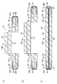
図7に示すように、第2実施形態の建物60は、第1実施形態の建物10(図1参照)の合成梁14に換えて、合成梁70が設けられた構成となっている。合成梁70は、軸方向の長さL6のプレキャスト部材70A、軸方向の長さL7のプレキャスト部材70B、及び軸方向の長さL8(=L7)のプレキャスト部材70Cが直線状に接合され形成されている。   As shown in FIG. 7, the building 60 of the second embodiment has a configuration in which a composite beam 70 is provided instead of the composite beam 14 of the building 10 (see FIG. 1) of the first embodiment. The composite beam 70 is formed by linearly joining a precast member 70A having an axial length L6, a precast member 70B having an axial length L7, and a precast member 70C having an axial length L8 (= L7). ing.

図7及び図8(a)に示すように、プレキャスト部材70Aは、合成梁70の左端部を構成しており、内部に梁主筋77A、あばら筋26、梁鉄骨28、及びシース管72(72A、72B)が設けられコンクリートで一体化されている。梁主筋77Aは、一端がU字状に形成された異形鉄筋である。また、あばら筋26は、プレキャスト部材70Aの軸方向で一方の端面から長さL2+L4の範囲において間隔d2をあけて配置されている。   As shown in FIGS. 7 and 8 (a), the precast member 70A constitutes the left end portion of the composite beam 70, and includes a beam main bar 77A, a stirrup 26, a beam steel frame 28, and a sheath tube 72 (72A). 72B) and integrated with concrete. The beam main bar 77A is a deformed bar having one end formed in a U shape. Further, the streaks 26 are arranged at a distance d2 in the range of length L2 + L4 from one end face in the axial direction of the precast member 70A.

また、プレキャスト部材70Aは、シース管72A、72Bが梁鉄骨28のウェブ28Aの両側で梁せい方向(矢印Z方向)の略中央に配設されている。そして、シース管72A、72B内にプレストレス部材としてのPC鋼線76A、76Bが挿通されており、端部に形成された凹部78において、PC鋼線76A、76Bの一端がそれぞれ定着具36で固定されている。なお、梁鉄骨28は、大半がプレキャスト部材70Aの左端部に長さL2の幅で埋設されており、一端がプレキャスト部材70Aの左端面から露出している。   Further, in the precast member 70A, sheath tubes 72A and 72B are disposed at substantially the center in the beam direction (arrow Z direction) on both sides of the web 28A of the beam steel frame 28. The PC steel wires 76A and 76B as prestress members are inserted into the sheath tubes 72A and 72B, and one end of each of the PC steel wires 76A and 76B is fixed to the fixing tool 36 in the recess 78 formed at the end. It is fixed. Note that most of the beam steel frames 28 are embedded in the left end portion of the precast member 70A with a width of length L2, and one end is exposed from the left end surface of the precast member 70A.

同様に、プレキャスト部材70Cは、合成梁70の右端部を構成しており、内部に梁主筋77A、あばら筋26、梁鉄骨28、及びシース管74(74A、74B)が設けられコンクリートで一体化されている。あばら筋26は、プレキャスト部材70Cの軸方向で一方の端面から長さL2+L4の範囲において、間隔d2をあけて配置されている。   Similarly, the precast member 70C constitutes the right end portion of the composite beam 70. The main beam 77A, the stirrup 26, the beam steel 28, and the sheath tube 74 (74A, 74B) are provided therein and integrated with concrete. Has been. The streaks 26 are arranged at an interval d2 within a range of length L2 + L4 from one end face in the axial direction of the precast member 70C.

また、プレキャスト部材70Cは、シース管74A、74Bが梁鉄骨28のウェブ28Aの両側で梁せい方向(矢印Z方向)の略中央に配設されている。そして、シース管74A、74B内にPC鋼線76A、76Bが挿通されており、端部に形成された凹部79において、PC鋼線76A、76Bの一端がそれぞれ定着具36で固定されている。なお、梁鉄骨28は、大半がプレキャスト部材70Cの右端部に長さL2の幅で埋設されており、一端がプレキャスト部材70Cの右端面から露出している。   Further, in the precast member 70C, the sheath tubes 74A and 74B are disposed at substantially the center in the beam direction (arrow Z direction) on both sides of the web 28A of the beam steel frame 28. The PC steel wires 76A and 76B are inserted into the sheath tubes 74A and 74B. One end of each of the PC steel wires 76A and 76B is fixed by the fixing tool 36 in the recess 79 formed at the end. Most of the beam steel frames 28 are embedded in the right end portion of the precast member 70C with a width of length L2, and one end is exposed from the right end surface of the precast member 70C.

図7及び図8(b)に示すように、プレキャスト部材70Bは、合成梁70の中央部を構成しており、内部に梁主筋77B、あばら筋26、梁鉄骨28、及びシース管73(73A、73B)が設けられコンクリートで一体化されている。梁主筋77Bは、直線状の異形鉄筋である。また、あばら筋26は、プレキャスト部材70Bの軸方向で間隔d1をあけて配置されている。シース管73A、73Bは、梁せい方向(矢印Z方向)の略中央に間隔をあけて配設されており、内部にPC鋼線76A、76Bが挿通されている。   As shown in FIGS. 7 and 8 (b), the precast member 70B constitutes the central portion of the composite beam 70, and includes a beam main bar 77B, a stirrup 26, a beam steel frame 28, and a sheath tube 73 (73A). 73B) and integrated with concrete. The beam main bar 77B is a linear deformed bar. Further, the streaks 26 are arranged with an interval d1 in the axial direction of the precast member 70B. The sheath tubes 73A and 73B are disposed at a substantially central position in the beam direction (arrow Z direction) with a space therebetween, and PC steel wires 76A and 76B are inserted therein.

ここで、合成梁70において、シース管72、73、74は同じ内径となっており、シース管72、73、74の内部が連通した状態でPC鋼線76が挿通され、ジャッキにより引張力が付与されて定着具36により固定された後、引張力が解除されることで合成梁70内にプレストレス力(圧縮力)が導入されている。なお、シース管72、73、74内にはグラウトは充填されておらず、PC鋼線76はアンボンド状態となっている。   Here, in the composite beam 70, the sheath tubes 72, 73, 74 have the same inner diameter, and the PC steel wire 76 is inserted in a state where the inside of the sheath tubes 72, 73, 74 is in communication, and the tensile force is applied by the jack. After being applied and fixed by the fixing tool 36, the prestressing force (compressive force) is introduced into the composite beam 70 by releasing the tensile force. The sheath tubes 72, 73, 74 are not filled with grout, and the PC steel wire 76 is in an unbonded state.

次に、合成梁70及び建物60の施工手順について説明する。   Next, the construction procedure of the composite beam 70 and the building 60 will be described.

図7に示すように、まず、プレキャスト部材70Aに合わせて形成された型枠(図示省略)内に梁主筋77A(図8(a)参照)及びあばら筋26を配置し、梁主筋77Aにあばら筋26を緊結する。そして、梁鉄骨28を貫通孔29が露出するように型枠の端部に配置し、型枠内で梁鉄骨28のウェブ28Aの両側にシース管72を配置する。このとき、シース管72の端部には凹部78を形成するための型枠を配置する。続いて、型枠内にコンクリートを打設し、所定の期間養生してから型枠を取り外すことによりプレキャスト部材70Aが形成される。   As shown in FIG. 7, first, the main beam 77A (see FIG. 8A) and the stirrup 26 are placed in a mold (not shown) formed in accordance with the precast member 70A, and the main beam 77A is separated. Tighten muscle 26. Then, the beam steel frame 28 is disposed at the end of the mold so that the through hole 29 is exposed, and the sheath tube 72 is disposed on both sides of the web 28A of the beam steel frame 28 in the mold. At this time, a mold for forming the recess 78 is disposed at the end of the sheath tube 72. Subsequently, concrete is placed in the mold, and after curing for a predetermined period, the mold is removed to form the precast member 70A.

同様に、プレキャスト部材70Cに合わせて形成された型枠(図示省略)内に梁主筋77A及びあばら筋26を配置し、梁主筋77Aにあばら筋26を緊結する。そして、梁鉄骨28を貫通孔29が露出するように型枠の端部に配置し、型枠内で梁鉄骨28のウェブ28Aの両側にシース管74を配置する。このとき、シース管74の端部には凹部79を形成するための型枠を配置する。続いて、型枠内にコンクリートを打設し、所定の期間養生してから型枠を取り外すことによりプレキャスト部材70Cが形成される。   Similarly, the main beam 77A and the stirrup 26 are arranged in a mold (not shown) formed in accordance with the precast member 70C, and the main stiffener 26 is connected to the main beam 77A. Then, the beam steel frame 28 is arranged at the end of the mold so that the through hole 29 is exposed, and the sheath tube 74 is arranged on both sides of the web 28A of the beam steel frame 28 in the mold. At this time, a mold for forming the recess 79 is disposed at the end of the sheath tube 74. Subsequently, concrete is placed in the mold, and after curing for a predetermined period, the mold is removed to form the precast member 70C.

一方、プレキャスト部材70Bに合わせて形成された型枠(図示省略)内に梁主筋77B(図8(b)参照)及びあばら筋26を配置し、梁主筋77Bにあばら筋26を緊結する。そして、型枠内にシース管73を配置する。続いて、型枠内にコンクリートを打設し、所定の期間養生してから型枠を取り外すことによりプレキャスト部材70Bが形成される。   On the other hand, the main beam 77B (see FIG. 8B) and the stirrup 26 are placed in a mold (not shown) formed in accordance with the precast member 70B, and the stirrup 26 is connected to the main beam 77B. And the sheath pipe | tube 73 is arrange | positioned in a formwork. Subsequently, concrete is cast in the mold, and after curing for a predetermined period, the mold is removed to form the precast member 70B.

続いて、プレキャスト部材70A、70B、70Cを直線状に配置して各端面を接触させ、シース管72、73、74の内部が連通した状態でシース管72、73、74内にPC鋼線76を挿通する。   Subsequently, the precast members 70A, 70B, and 70C are arranged in a straight line, the respective end surfaces are brought into contact with each other, and the PC steel wires 76 are placed in the sheath tubes 72, 73, and 74 in a state where the insides of the sheath tubes 72, 73, and 74 are in communication. Is inserted.

続いて、施工現場にてPC鋼線76の両端部を図示しないジャッキを用いて引っ張り、PC鋼線76に所定の引張力を導入すると共にPC鋼線76に定着具36の雄コーンを外挿した後、ジャッキを取り外す。このとき、PC鋼線76が元の状態に縮もうとする復元力によって定着具36の雄コーンが移動し、雌コーンと接触して、PC鋼線76の両端部が凹部78、79内に固定される。このようにして、合成梁70が形成される。なお、シース管72、73、74内にはグラウトを充填しない。   Subsequently, both ends of the PC steel wire 76 are pulled using a jack (not shown) at the construction site, a predetermined tensile force is introduced into the PC steel wire 76, and the male cone of the fixing tool 36 is extrapolated to the PC steel wire 76. After that, remove the jack. At this time, the male cone of the fixing tool 36 is moved by the restoring force of the PC steel wire 76 to shrink to the original state, and comes into contact with the female cone, so that both ends of the PC steel wire 76 are in the recesses 78 and 79. Fixed. In this way, the composite beam 70 is formed. The sheath tubes 72, 73, 74 are not filled with grout.

一方、地盤20(図1参照)上に複数の柱12を立設した後、各接合部40の間にクレーン(図示省略)を用いて合成梁70を配置する。そして、柱鉄骨22の接合部40と、梁鉄骨28の露出部28Dの位置を合わせた状態でプレート部材42を配置し、ボルト44により締結固定する。これにより、柱12への合成梁70の接合が完了する。続いて、合成梁70の接合が完了した後、小梁(図示省略)を配設し、型枠を配置してコンクリート打設することによりスラブ(図示省略)を形成する。このようにして、建物60が構築される。   On the other hand, after the plurality of pillars 12 are erected on the ground 20 (see FIG. 1), the composite beam 70 is disposed between the joints 40 using a crane (not shown). And the plate member 42 is arrange | positioned in the state which match | combined the position of the junction part 40 of the column steel frame 22, and the exposed part 28D of the beam steel frame 28, and it fastens and fixes with the volt | bolt 44. Thereby, the joining of the composite beam 70 to the column 12 is completed. Subsequently, after the joining of the composite beam 70 is completed, a small beam (not shown) is arranged, and a slab (not shown) is formed by placing a formwork and placing concrete. In this way, the building 60 is constructed.

次に、本発明の第2実施形態の作用について説明する。   Next, the operation of the second embodiment of the present invention will be described.

図7に示すように、合成梁70の両端部に梁鉄骨28が埋設されることにより、梁鉄骨28がプレキャスト部材70A、70Cとそれぞれ接合されている。ここで、合成梁70では、PC鋼線76により導入されているプレストレス力によって、プレキャスト部材70A、70B、70Cが接合しているが、プレキャスト部材70A、70Cと梁鉄骨28の接合にプレストレス力が必要とされていないため、従来のように鉄骨部材と鉄筋コンクリート部材をPC鋼線で接合させるものに比べて、プレストレス力を自由に設定できる。   As shown in FIG. 7, the beam steel frame 28 is bonded to the precast members 70 </ b> A and 70 </ b> C by embedding the beam steel frame 28 at both ends of the composite beam 70. Here, in the composite beam 70, the precast members 70 </ b> A, 70 </ b> B, 70 </ b> C are joined by the prestressing force introduced by the PC steel wire 76, but prestress is applied to the joining of the precast members 70 </ b> A, 70 </ b> C and the beam steel frame 28. Since no force is required, the prestressing force can be set freely as compared with the conventional case in which the steel member and the reinforced concrete member are joined with the PC steel wire.

これにより、合成梁70の必要とされるスパンが長くなっても、PC鋼線76によってプレキャスト部材70A、70B、70Cに必要な圧縮力を導入することができ、合成梁70が、長大スパン構造物の鉛直荷重に耐えることができる。また、合成梁70の左端部であるプレキャスト部材70A及び右端部であるプレキャスト部材70Cのみに梁鉄骨28が用いられているので、合成梁70全体を鉄骨部材で構成したものに較べて鉄骨量を減らすことができ、低コスト化が可能となる。   Thereby, even if the span required for the composite beam 70 becomes long, the compressive force required for the precast members 70A, 70B and 70C can be introduced by the PC steel wire 76, and the composite beam 70 has a long span structure. Can withstand vertical loads of objects. Moreover, since the beam steel frame 28 is used only for the precast member 70A which is the left end portion of the composite beam 70 and the precast member 70C which is the right end portion, the amount of the steel frame can be reduced as compared with a case where the entire composite beam 70 is configured by a steel member. The cost can be reduced and the cost can be reduced.

ここで、図9(a)〜(c)に示すように、合成梁70よりも長スパンの合成梁80を形成する場合、まず、接合部40(図7参照)のボルト44を外して合成梁70単体とし、さらに合成梁70の定着具36を緩めて外す。このとき、シース管72、73、74内にはグラウトが充填されておらず、PC鋼線76がアンボンド状態となっているため、PC鋼線76を引き抜いて取り除くことができる。そして、PC鋼線76を取り除くことで、合成梁70が、プレキャスト部材70A、70B、70Cに分割される。   Here, as shown in FIGS. 9A to 9C, when forming the composite beam 80 having a longer span than the composite beam 70, first, the bolts 44 of the joint 40 (see FIG. 7) are removed and combined. The beam 70 is a single unit, and the fixing tool 36 of the composite beam 70 is further loosened and removed. At this time, since the grout is not filled in the sheath tubes 72, 73, 74 and the PC steel wire 76 is in an unbonded state, the PC steel wire 76 can be pulled out and removed. Then, by removing the PC steel wire 76, the composite beam 70 is divided into precast members 70A, 70B, and 70C.

一方、プレキャスト部材70Bよりも長スパンのプレキャスト部材70Dを、プレキャスト部材70Bと同様の手順で、且つスパンが長い型枠を用いることで形成する。プレキャスト部材70Dは、シース管73よりも長いシース管82を有している。   On the other hand, a precast member 70D having a longer span than the precast member 70B is formed in the same procedure as the precast member 70B and using a mold having a long span. The precast member 70 </ b> D has a sheath tube 82 that is longer than the sheath tube 73.

続いて、プレキャスト部材70Bに換えてプレキャスト部材70Dを配置し、シース管72、82、74の内部を連通させた状態で、PC鋼線76よりも長いPC鋼線84をシース管72、82、74内に挿通する。そして、プレキャスト部材70A、70Bの凹部78、79においてPC鋼線84の両端部を定着具36で固定することにより、合成梁80が形成される。   Subsequently, the precast member 70D is disposed in place of the precast member 70B, and the PC steel wire 84, which is longer than the PC steel wire 76, is connected to the sheath tubes 72, 82, 74 is inserted. And the composite beam 80 is formed by fixing the both ends of the PC steel wire 84 with the fixing tool 36 in the recessed parts 78 and 79 of the precast members 70A and 70B.

このように、合成梁70を複数のプレキャスト部材70A、70B、70Cで形成しておき、中央部のプレキャスト部材70Bを長さの異なるプレキャスト部材70Dで置き換えることで、合成梁70のスパンを必要に応じて変更して、長大スパンの合成梁とすることができる。また、PC鋼線76をアンボンド状態としておくことで、合成梁70の各プレキャスト部材70A、70B、70Cへの分解及び交換が容易となると共に、各プレキャスト部材70A、70B、70Cを再利用することができる。なお、本実施形態ではPC鋼線76をアンボンド状態としたが、合成梁70の各プレキャスト部材70A、70B、70Cの交換が必要ない場合は、シース管72、73、74内にグラウトを充填してPC鋼線76を固定してもよい。   In this way, the composite beam 70 is formed of a plurality of precast members 70A, 70B, and 70C, and the center precast member 70B is replaced with a precast member 70D having a different length, so that the span of the composite beam 70 is required. It can be changed accordingly to make a long span composite beam. Further, by leaving the PC steel wire 76 in an unbonded state, the composite beam 70 can be easily disassembled and replaced with the precast members 70A, 70B, and 70C, and the precast members 70A, 70B, and 70C can be reused. Can do. In this embodiment, the PC steel wire 76 is in an unbonded state. However, if it is not necessary to replace the precast members 70A, 70B, 70C of the composite beam 70, the sheath tubes 72, 73, 74 are filled with grout. The PC steel wire 76 may be fixed.

なお、本発明は上記の実施形態に限定されない。   In addition, this invention is not limited to said embodiment.

柱12は、プレキャスト部材を積み上げて構築するものであってもよい。また、合成梁14は、施工現場においてPC鋼線34を引っ張り定着するポストテンション方式により形成していたが、他の実施例として図4(b)に示すように、プレテンション方式により合成梁50を形成してもよい。   The pillar 12 may be constructed by stacking precast members. The composite beam 14 is formed by a post-tension method in which the PC steel wire 34 is pulled and fixed at the construction site. However, as another embodiment, as shown in FIG. 4B, the composite beam 50 is formed by a pre-tension method. May be formed.

合成梁50は、まず、型枠内に梁主筋24(図2参照)及びあばら筋26を配置し、梁鉄骨28を貫通孔29が露出するように型枠の両端にそれぞれ配置してから、型枠内で梁鉄骨28のウェブ28Aの両側にPC鋼線52を配置する。続いて、PC鋼線52の両端部を図示しないジャッキを用いて引っ張り、PC鋼線52に所定の引張力を導入した状態で型枠内にコンクリートを打設する。そして、所定の期間養生してからジャッキ及び型枠を取り外すことにより形成される。   In the composite beam 50, first, the main beam 24 (see FIG. 2) and the stirrup 26 are arranged in the mold, and the beam steel frames 28 are arranged at both ends of the mold so that the through holes 29 are exposed. PC steel wires 52 are arranged on both sides of the web 28A of the beam steel frame 28 in the mold. Subsequently, both ends of the PC steel wire 52 are pulled using a jack (not shown), and concrete is placed in the mold with a predetermined tensile force introduced into the PC steel wire 52. And it forms by removing a jack and a formwork after curing for a predetermined period.

定着具36は、クサビ方式のものに限らず、例えば、ナットを緩めている間にPC鋼線34を引っ張り、所定の引張力を付与した後にナットを締結して定着するネジ方式のものを用いてもよい。また、接合部40における柱鉄骨22と梁鉄骨28の接合は、合成梁14のように再利用を前提としない場合において、溶接により接合してもよい。   The fixing device 36 is not limited to the wedge type, and for example, a screw type that pulls the PC steel wire 34 while loosening the nut and applies a predetermined tensile force to fasten the nut and fix it. May be. Further, the joining of the column steel frames 22 and the beam steel frames 28 in the joint portion 40 may be performed by welding in the case where reuse is not assumed as in the composite beam 14.

合成梁70の分割数は、プレキャスト部材70A、70B、70Cの3分割に限定されず、2分割又は4分割以上の複数分割であってもよい。また、各シース管及び各PC鋼線の数は、2本だけでなく4以上の偶数本であってもよい。さらに、プレストレス部材として、PC鋼線34、76、84だけでなくPC鋼棒を用いてもよい。   The number of divisions of the composite beam 70 is not limited to three divisions of the precast members 70A, 70B, and 70C, and may be two divisions or multiple divisions of four divisions or more. Moreover, the number of each sheath tube and each PC steel wire may be not only two but also an even number of four or more. Furthermore, you may use not only PC steel wire 34,76,84 but a PC steel rod as a prestress member.

10 建物
12 柱(柱)
14 合成梁(合成梁構造)
15 梁部材(梁部材)
26 あばら筋(せん断補強筋)
28 梁鉄骨(鉄骨部材)
28D 露出部(露出部)
32 シース管(シース管)
34 PC鋼線(プレストレス部材、PC鋼線)
40 接合部(接合部)
70 合成梁(合成梁構造)
70A プレキャスト部材(梁部材)
70B プレキャスト部材(梁部材)
70C プレキャスト部材(梁部材)
70D プレキャスト部材(梁部材)
72 シース管(シース管)
73 シース管(シース管)
74 シース管(シース管)
76 PC鋼線(プレストレス部材、PC鋼線)
80 合成梁(合成梁構造)
84 PC鋼線(プレストレス部材、PC鋼線)
10 Building 12 Pillar (pillar)
14 Composite beam (composite beam structure)
15 Beam members (beam members)
26 Stirrup (shear reinforcement)
28 Beam steel (steel member)
28D Exposed part (exposed part)
32 Sheath tube (sheath tube)
34 PC steel wire (prestressed member, PC steel wire)
40 joints (joints)
70 Composite beam (composite beam structure)
70A Precast member (beam member)
70B Precast member (beam member)
70C Precast member (beam member)
70D Precast member (beam member)
72 sheath tube (sheath tube)
73 Sheath tube (sheath tube)
74 Sheath tube (sheath tube)
76 PC steel wire (pre-stressed member, PC steel wire)
80 Composite beam (composite beam structure)
84 PC steel wire (pre-stressed member, PC steel wire)

Claims (4)

鉄筋コンクリート造の梁部材と、
前記梁部材の両端部に埋設され露出した露出部が、柱に設けられた接合部に接合される鉄骨部材と、
前記梁部材に圧縮力を導入するプレストレス部材と、
を有する合成梁構造。
Reinforced concrete beam members;
An exposed portion that is embedded and exposed at both ends of the beam member is a steel member that is joined to a joint provided on a column; and
A prestressing member for introducing a compressive force into the beam member;
Composite beam structure with
前記プレストレス部材は、前記梁部材に配置されたシース管へ挿通されたPC鋼線であり、前記PC鋼線には施工現場で引張力が導入され、前記シース管にグラウトを注入しない請求項1に記載の合成梁構造。   The pre-stress member is a PC steel wire inserted into a sheath tube disposed in the beam member, and a tensile force is introduced into the PC steel wire at a construction site, and no grout is injected into the sheath tube. The composite beam structure according to 1. 前記プレストレス部材は、前記梁部材に配置されたシース管へ挿通されたPC鋼線であり、前記PC鋼線には施工現場で引張力が導入され、前記シース管にグラウトが注入される請求項1に記載の合成梁構造。   The pre-stress member is a PC steel wire inserted into a sheath tube disposed in the beam member, and a tensile force is introduced into the PC steel wire at a construction site, and grout is injected into the sheath tube. Item 3. The composite beam structure according to Item 1. 前記梁部材には複数のせん断補強筋が設けられ、該複数のせん断補強筋の配置間隔が、前記梁部材の中央部よりも両端部で狭くなっている請求項1から請求項3のいずれか1項に記載の合成梁構造。   4. The beam member according to claim 1, wherein a plurality of shear reinforcement bars are provided on the beam member, and an interval between the plurality of shear reinforcement bars is narrower at both ends than a central portion of the beam member. The composite beam structure according to item 1.
JP2010131053A 2010-06-08 2010-06-08 Composite beam structure Expired - Fee Related JP5613465B2 (en)

Priority Applications (1)

Application Number Priority Date Filing Date Title
JP2010131053A JP5613465B2 (en) 2010-06-08 2010-06-08 Composite beam structure

Applications Claiming Priority (1)

Application Number Priority Date Filing Date Title
JP2010131053A JP5613465B2 (en) 2010-06-08 2010-06-08 Composite beam structure

Publications (2)

Publication Number Publication Date
JP2011256575A true JP2011256575A (en) 2011-12-22
JP5613465B2 JP5613465B2 (en) 2014-10-22

Family

ID=45473054

Family Applications (1)

Application Number Title Priority Date Filing Date
JP2010131053A Expired - Fee Related JP5613465B2 (en) 2010-06-08 2010-06-08 Composite beam structure

Country Status (1)

Country Link
JP (1) JP5613465B2 (en)

Cited By (1)

* Cited by examiner, † Cited by third party
Publication number Priority date Publication date Assignee Title
JP2019015062A (en) * 2017-07-05 2019-01-31 鹿島建設株式会社 Concrete floor slab construction method

Citations (6)

* Cited by examiner, † Cited by third party
Publication number Priority date Publication date Assignee Title
JPH025520U (en) * 1988-06-22 1990-01-16
JPH0396554A (en) * 1989-09-08 1991-04-22 Oriental Kensetsu Kk Non-corrosive reinforcing member embedding prestressed concrete member
JPH05340031A (en) * 1992-06-04 1993-12-21 Kawada Kensetsu Kk Prestressed concrete girder and its manufacture
JPH0657967A (en) * 1992-08-07 1994-03-01 Taisei Corp Framing method of building capable of reusing pc member
JPH11172786A (en) * 1997-12-09 1999-06-29 Takenaka Komuten Co Ltd Dry pressure bonding method of precast concrete member
JP2004316322A (en) * 2003-04-18 2004-11-11 Takenaka Komuten Co Ltd Construction method of column-beam skeleton by precast concrete member

Patent Citations (6)

* Cited by examiner, † Cited by third party
Publication number Priority date Publication date Assignee Title
JPH025520U (en) * 1988-06-22 1990-01-16
JPH0396554A (en) * 1989-09-08 1991-04-22 Oriental Kensetsu Kk Non-corrosive reinforcing member embedding prestressed concrete member
JPH05340031A (en) * 1992-06-04 1993-12-21 Kawada Kensetsu Kk Prestressed concrete girder and its manufacture
JPH0657967A (en) * 1992-08-07 1994-03-01 Taisei Corp Framing method of building capable of reusing pc member
JPH11172786A (en) * 1997-12-09 1999-06-29 Takenaka Komuten Co Ltd Dry pressure bonding method of precast concrete member
JP2004316322A (en) * 2003-04-18 2004-11-11 Takenaka Komuten Co Ltd Construction method of column-beam skeleton by precast concrete member

Cited By (1)

* Cited by examiner, † Cited by third party
Publication number Priority date Publication date Assignee Title
JP2019015062A (en) * 2017-07-05 2019-01-31 鹿島建設株式会社 Concrete floor slab construction method

Also Published As

Publication number Publication date
JP5613465B2 (en) 2014-10-22

Similar Documents

Publication Publication Date Title
JP5258099B2 (en) Prestressed concrete pile, method for manufacturing the same, and method for connecting pile head and footing
KR101440434B1 (en) Construction Method for Composite Type Rahmen Bridge
KR101937680B1 (en) Prefabricated Precast Structure and Construction Method Thereof
KR101495039B1 (en) A constructing method of structure using sandwich PC-wall
KR102075165B1 (en) Concrete filled tubular column and connecting structure of the same and construction method thereof
WO2011077822A1 (en) Half precast floor plank, and slab construction method using same
KR20100121866A (en) Pc slave for building having reinforcement structure as a set
JP2018135688A (en) Bridge pier and construction method thereof
KR101328045B1 (en) Reinforced concrete composite columns using precast high-performance fiber-reinforced cement
JP2015004229A (en) Pc earthquake-poof joining structure and pc earthquake-proof joining method of column-beam of using steel frame pin
JP2008266910A (en) Projection structure of anchorage or deviator of tendon, and construction method therefor
JP4834890B2 (en) Prestressing method for filling part between precast concrete members
JP5602455B2 (en) Beam members and building structures
JP5613465B2 (en) Composite beam structure
JP2003227236A (en) Permanent and emergent aseismatic reinforcement method for column with wall
KR101311207B1 (en) Column of steel framed reinforced precast concrete structure, manufacturing methods for the same, and construction methods for the same
JP6918469B2 (en) Construction method of precast member, erection structure of precast member, erection structure of precast member
KR101698807B1 (en) Manufacturing method of the psc girder using the corrugated steel plate and the psc girder manufactured thereby
JP5750246B2 (en) Composite beam, building, and composite beam construction method
JP5439016B2 (en) Buried formwork
KR100695491B1 (en) A fixing device, a pre-fabricating forms for concrete-structure and the construction method thereof
JP5024617B2 (en) Prestressed concrete beam and its construction method
JP2831934B2 (en) How to build substructure
JP2009108500A (en) Precast beam construction method, precast beam, precast beam joint structure, and building
JP2017206844A (en) Earthquake resistant wall structure

Legal Events

Date Code Title Description
A621 Written request for application examination

Free format text: JAPANESE INTERMEDIATE CODE: A621

Effective date: 20130326

A977 Report on retrieval

Free format text: JAPANESE INTERMEDIATE CODE: A971007

Effective date: 20131213

A131 Notification of reasons for refusal

Free format text: JAPANESE INTERMEDIATE CODE: A131

Effective date: 20131217

A521 Written amendment

Free format text: JAPANESE INTERMEDIATE CODE: A523

Effective date: 20140210

TRDD Decision of grant or rejection written
A01 Written decision to grant a patent or to grant a registration (utility model)

Free format text: JAPANESE INTERMEDIATE CODE: A01

Effective date: 20140826

A61 First payment of annual fees (during grant procedure)

Free format text: JAPANESE INTERMEDIATE CODE: A61

Effective date: 20140908

R150 Certificate of patent or registration of utility model

Ref document number: 5613465

Country of ref document: JP

Free format text: JAPANESE INTERMEDIATE CODE: R150

LAPS Cancellation because of no payment of annual fees