JP2011199936A - Linear motor and armature structure thereof - Google Patents
Linear motor and armature structure thereof Download PDFInfo
- Publication number
- JP2011199936A JP2011199936A JP2010060931A JP2010060931A JP2011199936A JP 2011199936 A JP2011199936 A JP 2011199936A JP 2010060931 A JP2010060931 A JP 2010060931A JP 2010060931 A JP2010060931 A JP 2010060931A JP 2011199936 A JP2011199936 A JP 2011199936A
- Authority
- JP
- Japan
- Prior art keywords
- armature
- tooth
- width dimension
- root
- teeth
- Prior art date
- Legal status (The legal status is an assumption and is not a legal conclusion. Google has not performed a legal analysis and makes no representation as to the accuracy of the status listed.)
- Granted
Links
Images


Classifications
-
- H—ELECTRICITY
- H02—GENERATION; CONVERSION OR DISTRIBUTION OF ELECTRIC POWER
- H02K—DYNAMO-ELECTRIC MACHINES
- H02K41/00—Propulsion systems in which a rigid body is moved along a path due to dynamo-electric interaction between the body and a magnetic field travelling along the path
- H02K41/02—Linear motors; Sectional motors
- H02K41/03—Synchronous motors; Motors moving step by step; Reluctance motors
- H02K41/031—Synchronous motors; Motors moving step by step; Reluctance motors of the permanent magnet type
-
- H—ELECTRICITY
- H02—GENERATION; CONVERSION OR DISTRIBUTION OF ELECTRIC POWER
- H02K—DYNAMO-ELECTRIC MACHINES
- H02K1/00—Details of the magnetic circuit
- H02K1/06—Details of the magnetic circuit characterised by the shape, form or construction
- H02K1/12—Stationary parts of the magnetic circuit
- H02K1/16—Stator cores with slots for windings
- H02K1/165—Shape, form or location of the slots
Abstract
Description
本発明は、リニアモータおよびその電機子構造に関し、特にサーボ制御に用いるのに適した低推力脈動、低ディテント推力でありながら大推力を発生可能なリニアモータに関するものである。また、本発明は、特に大出力や大推力を発生させて射出成形機の射出軸やプレス機械の加圧ラム(主軸)などに要求される高加速動作を実現するための駆動用モータを主たる対象とするものである。 The present invention relates to a linear motor and an armature structure thereof, and more particularly to a linear motor capable of generating a large thrust while having low thrust pulsation and low detent thrust suitable for use in servo control. The present invention mainly provides a drive motor for generating a high output and a large thrust to realize a high acceleration operation required for an injection shaft of an injection molding machine, a pressurization ram (main shaft) of a press machine, and the like. It is intended.
リニアモータは、所定の設計形状の電磁鋼板を積層して作ったコアに電線を巻回して固定子コイルとした固定子と、構造部品に設けた磁石挿入用空間に永久磁石を挿入し固定した可動子とを組合せて構成されか、または、上記と逆にコアに電線を巻回して可動子コイルとした可動子と、構造部品に設けた磁石挿入用空間に永久磁石を挿入し固定した固定子とを組合せて構成される。 A linear motor is a stator in which a coil is formed by winding an electric wire around a core made by laminating electromagnetic steel sheets of a predetermined design shape, and a permanent magnet is inserted and fixed in a magnet insertion space provided in a structural component. The mover is combined with the mover, or the mover coil is formed by winding an electric wire around the core in the opposite manner, and the permanent magnet is inserted and fixed in the magnet insertion space provided in the structural part. Composed of a combination of children.
近年、大出力や大推力が必要な射出成形機の射出軸やプレス機械の加圧ラムなどにおいても、制御性能の向上や高加速動作などを目的にこの種のモータを用いる需要が強くなってきている。しかし、リニアモータはその原理上、大推力を得るにはコア付方式が必要であり、固定子に対する可動子の位置に応じての磁気特性の変化が大きいため、可動子のどの位置でも安定した動作特性が望まれる位置決め特性が重要な自動加工機の機械軸の駆動用としては、出力範囲に限界がある。例えば、位置に応じて可動子に発生する外乱推力であるディテント推力(無励磁の状態で可動子に変位を与えようとした場合に発生する反発力)や、推力対推力電流の比率である推力定数の可動子位置ごとの変動(推力脈動率)は大きいものである。 In recent years, there has been a growing demand for using this type of motor for the purpose of improving control performance and high acceleration operation in injection shafts of injection molding machines and press rams of press machines that require high output and large thrust. ing. However, in principle, a linear motor requires a cored system in order to obtain a large thrust, and the magnetic characteristics change greatly depending on the position of the mover relative to the stator, so it is stable at any position of the mover. There is a limit in the output range for driving the machine shaft of an automatic machine, which is important for positioning characteristics where motion characteristics are desired. For example, a detent thrust (a repulsive force generated when an attempt is made to displace the mover in a non-excited state), which is a disturbance thrust generated in the mover according to the position, or a thrust that is a ratio of thrust to thrust current The constant fluctuation (thrust pulsation rate) for each mover position is large.
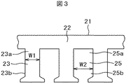
従来のこの種のリニアモータに採用される固定子側(または可動子側)の電磁鋼板の形状としては、図4に示すようにティース23の幅W1が可動子対向側(または固定子対向側)であるティース先端側23bからティース付根部側23aに向けて同一とし、かつ、スロット25の幅W2が開口部側25bから底部側25aに向けて同一となした、いわゆる「平行ティース、平行スロット」が一般的であった。このため、選択できる形状パラメータが少なく、最適設計を妨げていた。
As the shape of the electromagnetic steel plate on the stator side (or mover side) employed in the conventional linear motor of this type, the width W1 of the
また、前記用途のリニアモータに対しては、大推力であるとともに、高加速度を実現しやすいように可動子重量が小さいことが求められる。しかし、可動子重量を小さくするには可動子の寸法を小さくすることになるが、総磁束量が小さくなる問題がある。これを補うためにコイル電流を大きくして出力トルクを増大させようとすると、ティースの磁束密度が大きくなりすぎて隣接するティース間の漏れ磁束が増加して特性が頭打ちとなる。すなわち、大推力と高加速度の両者を満足させることは困難であった。 In addition, the linear motor for the above application is required to have a large thrust and a small mover weight so that high acceleration can be easily realized. However, to reduce the weight of the mover, the size of the mover is reduced, but there is a problem that the total magnetic flux amount is reduced. In order to compensate for this, if the coil current is increased to increase the output torque, the magnetic flux density of the teeth becomes too high, and the leakage magnetic flux between the adjacent teeth increases, resulting in a peak characteristic. That is, it was difficult to satisfy both large thrust and high acceleration.
上記の対策として、固定子コア(または可動子コア)のティースの幅寸法を大きくすることが考えられるが、その分スロット幅が小さくなってコイルの断面積が少なくなって電流を増加できないという問題がある。 As a measure for the above, it is conceivable to increase the width of the teeth of the stator core (or the mover core). There is.
特許文献1(特開2008−017694号)、特許文献2(特開2006−025505号)には、磁気飽和限界を高くして推力を向上させたリニアモータが示されている。可動子の磁極を固定子から遠ざかるほど広くなるように形成することにより、磁気飽和限界を高く設定している。 Patent Document 1 (Japanese Patent Laid-Open No. 2008-017694) and Patent Document 2 (Japanese Patent Laid-Open No. 2006-025505) show linear motors in which the magnetic saturation limit is increased to improve thrust. The magnetic saturation limit is set high by forming the magnetic pole of the mover so as to become wider as it moves away from the stator.
しかしながら、外乱推力である上記ディテント推力は、可動子(または固定子)に接近して対向する固定子(または可動子)のティース幅とスロット幅の関係によって左右され、それぞれの寸法の関係を吟味しないと、外乱の低減と大きな推力を得る上でよい結果が得られない。また、他の外乱トルクとして、推力対推力電流の比率である推力定数の可動子位置ごとの変動(推力脈動率)についても同様である。特許文献1、特許文献2においては、出力可能最大推力、水力脈動率、ディテント推力について要求性能を満たす上での最適設定については考慮されていない。
However, the above-mentioned detent thrust, which is a disturbance thrust, depends on the relationship between the teeth width and slot width of the stator (or mover) that is close to and facing the mover (or stator), and examines the relationship between the dimensions. Otherwise, good results cannot be obtained in reducing disturbance and obtaining a large thrust. Further, as other disturbance torques, the same applies to the variation (thrust pulsation rate) of the thrust constant, which is the ratio of thrust to thrust current, for each mover position. In
本発明は、電機子コイルが巻装されるティースとスロットの幅に関して適切な関係を設定することにより、外乱推力を少なくし、これによって可動子の移動位置に沿って一様で大きな推力が得られ、かつ、高加速度制御を行えるリニアモータ及びその電機子構造を提供するものである。 The present invention reduces the disturbance thrust by setting an appropriate relationship with respect to the teeth and slot widths around which the armature coil is wound, thereby obtaining a uniform and large thrust along the moving position of the mover. In addition, a linear motor capable of performing high acceleration control and an armature structure thereof are provided.
上記課題を解決するため本発明は、複数の永久磁石を並べて配置した磁極と、上記永久磁石列と磁気的空間を介して対向すると共に、対向面に複数のスロットとティースを有する電機子に電機子コイルを巻装した電機子とを備え、上記磁極と上記電機子との何れか一方を固定子に、他方を可動子として、上記磁極と上記電機子を相対的に走行するようにしたリニアモータにおいて、
上記電機子の上記ティース幅寸法がティース先端から付根部に向い漸次増加し、ティースとスロットとの幅寸法の比率(ティース幅寸法/スロットとの幅寸法)がティース先端から付根部に向い漸次増加していることを特徴とする。
In order to solve the above-described problems, the present invention provides an armature having an armature having a plurality of permanent magnets arranged side by side, a permanent magnet array opposed to the permanent magnet array via a magnetic space, and a plurality of slots and teeth on an opposing surface. A linear arm provided with an armature around which a child coil is wound, wherein either one of the magnetic pole and the armature is a stator and the other is a mover, and the magnetic pole and the armature are relatively driven. In the motor
The tooth width dimension of the armature gradually increases from the tooth tip toward the root, and the ratio of the width dimension between the teeth and the slot (tooth width dimension / slot width dimension) gradually increases from the tooth tip toward the root. It is characterized by that.
また、本発明は、複数の永久磁石を並べて配置した磁極と、上記永久磁石列と磁気的空間を介して対向すると共に、対向面に複数のスロットとティースを有する電機子に電機子コイルを巻装した電機子とを備え、上記磁極と上記電機子との何れか一方を固定子に、他方を可動子として、上記磁極と上記電機子を相対的に走行するようにしたリニアモータにおいて、
上記電機子の上記ティース幅寸法がティース先端から付根部に向い所定の長さ区間一定であり、上記区間からティース付根部に向い漸次増加し、ティースとスロットとの幅寸法の比率(ティース幅寸法/スロットとの幅寸法)がティース先端から付根部に向い漸次増加していることを特徴とする。
Further, the present invention provides an armature coil wound around an armature having a plurality of permanent magnets arranged side by side and an armature having a plurality of slots and teeth opposed to the permanent magnet array via a magnetic space. In a linear motor provided with a mounted armature, wherein either one of the magnetic pole and the armature is a stator and the other is a mover, and the magnetic pole and the armature are relatively driven.
The tooth width dimension of the armature is constant for a predetermined length from the tooth tip to the root, and gradually increases from the section toward the tooth root, and the ratio of the width dimension between the teeth and the slot (tooth width dimension). (Width dimension with the slot) is gradually increased from the tip of the tooth toward the root.
また、上記のリニアモータにおいて、上記電機子に巻装される電機子コイルの巻回数が、ティース先端側よりティース付根部側で少なく設定されたことを特徴とする。 In the above linear motor, the number of turns of the armature coil wound around the armature is set to be smaller on the tooth root side than on the tooth tip side.
また、電機子構造として、上記電機子の上記ティース幅寸法がティース先端から付根部に向い漸次増加し、ティースとスロットとの幅寸法の比率(ティース幅寸法/スロットとの幅寸法)がティース先端から付根部に向い漸次増加していることを特徴とする。 In the armature structure, the tooth width dimension of the armature gradually increases from the tooth tip toward the root, and the ratio of the width dimension between the tooth and the slot (tooth width dimension / width dimension with the slot) is the tooth tip. It is characterized by gradually increasing from the root toward the root.
また、電機子構造として、上記電機子の上記ティース幅寸法がティース先端から付根部に向い所定の長さ区間一定であり、上記区間からティース付根部に向い漸次増加し、ティースとスロットとの幅寸法の比率(ティース幅寸法/スロットとの幅寸法)がティース先端から付根部に向い漸次増加していることを特徴とする。 Further, as the armature structure, the width of the teeth of the armature is constant for a predetermined length from the tip of the tooth toward the root, and gradually increases from the section toward the root of the tooth. The ratio of dimensions (tooth width dimension / slot width dimension) gradually increases from the tip of the tooth toward the root.
また、上記電機子構造において、上記電機子に巻装される電機子コイルの巻回数が、ティース先端側よりティース付根部側で少なく設定されたことを特徴とする。 In the armature structure, the number of turns of the armature coil wound around the armature is set to be smaller on the tooth root side than on the tooth tip side.
本発明によれば、外乱推力を少なくすることで可動子の移動位置に沿って一様で大きな推力が得られ、高加速度制御を行うことができる。 According to the present invention, by reducing the disturbance thrust, a uniform and large thrust can be obtained along the moving position of the mover, and high acceleration control can be performed.
以下、本発明の各実施例について図面を用いて説明する。実施例においては、複数の永久磁石を並べて配置した界磁極を可動子とし、上記界磁極に磁気的空間を介して対向する電機子コアに電機子コイルを巻装した電機子を固定子としている。 Embodiments of the present invention will be described below with reference to the drawings. In the embodiment, a field pole in which a plurality of permanent magnets are arranged side by side is used as a mover, and an armature in which an armature coil is wound around an armature core that faces the field pole via a magnetic space is used as a stator. .
本発明の実施例1を図1に示す。1は電磁鋼板を積層して構成されたコアが直線状に延びる電機子(固定子)、2は電機子の背部、3は電機子に形成された複数のティース(図では3個のティースを示す。)、5はティース3の間に形成された複数のスロット、4は各ティース3を巻回するように各スロット5内に挿入された複数の電機子コイルである。ティース3には電機子の背部側の付根部3aとティース先端側3bとがあり、スロット5には電機子の背部側の底部5aと先端側の開口部5bとがある。8は電機子1のティース先端3bおよびスロット開口部5b側と磁気的空間を介して対向し、直線状に延びる所定長さの可動子であり、対向面に複数の永久磁石7が所定ピッチで並べて埋設されている。図では、コイル4が1個のスロットの一部にのみ挿入された状態を示している。
A first embodiment of the present invention is shown in FIG. DESCRIPTION OF
上記構成において、固定子の電機子1に巻回された複数の電機子コイル4に三相交流を流すことにより、電機子1に移動磁界を発生させ、この移動磁界に永久磁石7を順次磁気吸引することにより、可動子としての磁極8を、矢印方向に直線移動させる。実際には、磁極8には移動テーブルなどを固定して直線移動させることになる。
In the above configuration, a three-phase alternating current is passed through the plurality of
本実施例では、付根部3aでのティース3の幅寸法をWt5、ティース先端3bでの幅寸法をWt4とし、スロット5の底部5aの幅寸法をS5、開口部5bでの幅寸法をS4としている。そして、電機子1のティース3の幅寸法がティース先端3bからティース付根部3aに向い漸次増加し、Wt4<Wt5になるように設定されている。また、スロット5の幅寸法が開口部4bから底部4aに向い漸次減少し、S4>S5になるように設定されている。
In this embodiment, the width dimension of the
上記のように実施例1は、ティース付根部の幅WT5に対してティース先端部の幅WT4を小さくし、また、スロット底部5aでの幅S5に対して、スロット開口部5bでの幅S4を大きくした形状となっている。
As described above, in the first embodiment, the width WT4 of the tooth tip is made smaller than the width WT5 of the tooth root, and the width S4 at the
図3に従来例の電機子(固定子)形状を示す。ここで電機子21は図1の電機子1と同一外形寸法あるとし、ティース形状は付根部23aの幅寸法(図1のWT5に相当)とティース先端23bの幅寸法(図1のWT4に相当)とが同じW1であり、スロットの幅寸法は底部25aと開口部25bで同じ幅寸法W2である。
FIG. 3 shows a conventional armature (stator) shape. Here, the
電機子のティースに巻回される巻線の巻回数および並列本数が同じであり、巻線に流入する電流が同じ場合、図3において電機子21のティースの幅をできるだけ大きくとることにより、ティース部分での磁気飽和が緩和され、ティース部分の有効磁束量が増大する。これにより、出力できるトルクの最大値を増大させることが可能となる。しかし、ティースの幅を広げるとスロットの幅が狭まるので、巻線の巻回数が減って発生磁束が減少する問題がある。電機子21のコアのティース23に流れ込んだ磁束が磁気抵抗の小さい背部22に流れようとしてティースの付根部3aに磁気が集中して飽和し易くなる。そこで実施例1では、ティース3の先端3bより付根部3aの幅を広げて、磁気飽和を緩和することで、ティース部分の有効磁束量を増大させている。
When the number of windings and the number of parallel windings wound around the armature teeth are the same and the current flowing into the windings is the same, the teeth of the
ここで、ティース及びスロットについての形状は自由に選定していくことは可能であるが、最大出力推力と、各位置での一様な推力特性とを両立させることは容易ではない。特に、機械の可動部分の加速性能を向上するには駆動するモータ自体の可動子重量を小さくすることが必要であり、これによって可動子の長さは決まってしまう。固定子の可動子側の形状(ティース、スロットの寸法)は可動子長さと関連付けられているため、ティースなどに与えられる寸法をあまり小さくできず限界が生じる。 Here, the shapes of the teeth and the slots can be freely selected, but it is not easy to achieve both the maximum output thrust and the uniform thrust characteristics at each position. In particular, in order to improve the acceleration performance of the movable part of the machine, it is necessary to reduce the weight of the movable element of the motor itself to be driven, and this determines the length of the movable element. Since the shape of the stator on the side of the mover (the dimensions of the teeth and slots) is related to the length of the mover, the dimension given to the teeth cannot be made very small, and there is a limit.
本発明の実施例2を図2に示す。図1と同一部分には同一符号で示す。本実施例2では、前記電機子1のティース部3の幅寸法(Wt4)がティース先端側3bから付根側3aに向けて、ティース部3の長さの約中央の位置3cまでの区間(所定の長さ区間)で一定(Wt4)である。そして、前記位置3cから付根側3aに向けて漸次増加し、付根側3aで幅寸法Wt5となる。さらに、スロット5の幅寸法(S4)が開口部5bから底部5aに向けて、スロット部5の長さの約中央の位置5cまでの区間(所定の長さ区間)で一定(S4)である。そして、前記位置5cから底部5aに向けて漸次減少し、底部5aで幅寸法S5となる。
A second embodiment of the present invention is shown in FIG. The same parts as those in FIG. In the second embodiment, the width (Wt4) of the
本実施例2は先の実施例と同様に、ティース3とスロット5との幅寸法の比率(ティース幅寸法/スロット幅寸法)がティース先端から付根部に向かい漸次増加している。
In the second embodiment, as in the previous embodiment, the ratio of the width dimension between the
従って、実施例1と同様にティースの付根3aの幅寸法をできるだけ大きくWt5としており、磁気飽和が緩和されてティース部分の有効磁束量が増大する。
Accordingly, the width dimension of the
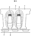
上記実施例によれば、スロット5の開口部5bと底部5aでは幅寸法が異なって、S4>S5の関係にあるため、電機子コイル4の巻回数が開口部5b付近で多く、底部5aで少なくなる。従って、コイル電流による磁束がスロット5の開口部5b付近での増加し、底部5aで減少することになる。図4にスロット5の底部5aのコイルによる磁束の流れを示し、図5にスロット5の開口側5b付近のコイルによる磁束の流れを示す。
According to the above embodiment, the
スロット5の底部5aのコイル4による磁束は、この底部5aを中心とする円形の磁束が発生するため、図4に示すようにティース先端まで届きにくく、ティース間を横切る漏れ磁束が生じ易い。本実施例では、スロット5の底部5a付近のコイルによる磁束が減少するようにスロットの幅寸法が設定されているので、ティース間での漏れ磁束を少なく抑えることができる。
The magnetic flux generated by the
スロット5の開口部5b付近のコイル4による磁束は、このコイル4を中心とした円形の磁束を発生するが、図5に示すようにティース先端5bが近いために、可動子8を流れる磁束となって可動子の推力として有効に作用する。本実施例では、スロット5の開口部5b側のコイルによる磁束が増加するようにスロットの幅寸法が設定されているため、可動子の推力をより大きくすることができる。また、ティース付根3aの幅寸法を大きく設定しているのでティース付根3aの磁気抵抗が下がるため、開口部5b側のコイルによる磁束は、ほぼ全て電機子1の背部2を通すことができ、磁気飽和による特性低下やティース間の漏れ磁束を防止することができる。
The magnetic flux generated by the
本実施例の固定子としての電機子1を用い、これと可動子としての磁極8を組合せてリニアモータを構成した場合、同じサイズおよび可動子の重量でありながら、要求される出力可能最大推力と可動子重量について、最も有利なリニアモータの特性を実現でき、射出成形機の射出性能の向上や制御性能の向上、また、プレス機械のプレス性能の向上や品質向上が実現できる。
When the
1…電機子コア(固定子)、2…電機子の背部、3…ティース、3a…ティース付根、3b…ティース先端、3c…ティース中央位置、4…電機子コイル、5…スロット、5a…スロット底部、5b…スロット開口部、5c…スロット中央部、7…永久磁石、8…可動子。
DESCRIPTION OF
Claims (8)
上記電機子の上記ティース幅寸法がティース先端から付根部に向い漸次増加し、ティースとスロットとの幅寸法の比率(ティース幅寸法/スロットとの幅寸法)がティース先端から付根部に向い漸次増加していることを特徴とするリニアモータ。 A magnetic pole in which a plurality of permanent magnets are arranged side by side, and an armature in which an armature coil is wound around an armature having a plurality of slots and teeth on the opposing surface while facing the permanent magnet array via a magnetic space. A linear motor configured to travel relatively between the magnetic pole and the armature, with one of the magnetic pole and the armature as a stator and the other as a mover,
The tooth width dimension of the armature gradually increases from the tooth tip toward the root, and the ratio of the width dimension between the teeth and the slot (tooth width dimension / slot width dimension) gradually increases from the tooth tip toward the root. A linear motor characterized by
上記電機子の上記ティース幅寸法がティース先端から付根部に向い所定の長さ区間一定であり、上記区間からティース付根部に向い漸次増加し、ティースとスロットとの幅寸法の比率(ティース幅寸法/スロットとの幅寸法)がティース先端から付根部に向い漸次増加していることを特徴とするリニアモータ。 A magnetic pole in which a plurality of permanent magnets are arranged side by side, and an armature in which an armature coil is wound around an armature having a plurality of slots and teeth on the opposing surface while facing the permanent magnet array via a magnetic space. A linear motor configured to travel relatively between the magnetic pole and the armature, with one of the magnetic pole and the armature as a stator and the other as a mover,
The tooth width dimension of the armature is constant for a predetermined length from the tooth tip to the root, and gradually increases from the section toward the tooth root, and the ratio of the width dimension between the teeth and the slot (tooth width dimension). (/ Width dimension with the slot) is gradually increased from the tip of the tooth toward the root.
上記電機子の上記ティース幅寸法がティース先端から付根部に向い漸次増加し、ティースとスロットとの幅寸法の比率(ティース幅寸法/スロットとの幅寸法)がティース先端から付根部に向い漸次増加していることを特徴とする電機子構造。 A magnetic pole in which a plurality of permanent magnets are arranged side by side, and an armature in which an armature coil is wound around an armature having a plurality of slots and teeth on the opposing surface while facing the permanent magnet array via a magnetic space. In an armature structure of a linear motor, wherein either one of the magnetic pole and the armature is a stator and the other is a mover, and the magnetic pole and the armature are relatively driven.
The tooth width dimension of the armature gradually increases from the tooth tip toward the root, and the ratio of the width dimension between the teeth and the slot (tooth width dimension / slot width dimension) gradually increases from the tooth tip toward the root. Armature structure characterized by
上記電機子の上記ティース幅寸法がティース先端から付根部に向い所定の長さ区間一定であり、上記区間からティース付根部に向い漸次増加し、ティースとスロットとの幅寸法の比率(ティース幅寸法/スロットとの幅寸法)がティース先端から付根部に向い漸次増加していることを特徴とする電機子構造。 A magnetic pole in which a plurality of permanent magnets are arranged side by side, and an armature in which an armature coil is wound around an armature having a plurality of slots and teeth on the opposing surface while facing the permanent magnet array via a magnetic space. In an armature structure of a linear motor, wherein either one of the magnetic pole and the armature is a stator and the other is a mover, and the magnetic pole and the armature are relatively driven.
The tooth width dimension of the armature is constant for a predetermined length from the tooth tip to the root, and gradually increases from the section toward the tooth root, and the ratio of the width dimension between the teeth and the slot (tooth width dimension). Armature structure, wherein the width dimension with respect to the slot) gradually increases from the tip of the tooth toward the root.
Priority Applications (1)
| Application Number | Priority Date | Filing Date | Title |
|---|---|---|---|
| JP2010060931A JP5452299B2 (en) | 2010-03-17 | 2010-03-17 | Linear motor and its armature structure |
Applications Claiming Priority (1)
| Application Number | Priority Date | Filing Date | Title |
|---|---|---|---|
| JP2010060931A JP5452299B2 (en) | 2010-03-17 | 2010-03-17 | Linear motor and its armature structure |
Publications (2)
| Publication Number | Publication Date |
|---|---|
| JP2011199936A true JP2011199936A (en) | 2011-10-06 |
| JP5452299B2 JP5452299B2 (en) | 2014-03-26 |
Family
ID=44877460
Family Applications (1)
| Application Number | Title | Priority Date | Filing Date |
|---|---|---|---|
| JP2010060931A Expired - Fee Related JP5452299B2 (en) | 2010-03-17 | 2010-03-17 | Linear motor and its armature structure |
Country Status (1)
| Country | Link |
|---|---|
| JP (1) | JP5452299B2 (en) |
Cited By (10)
| Publication number | Priority date | Publication date | Assignee | Title |
|---|---|---|---|---|
| WO2014020695A1 (en) * | 2012-07-31 | 2014-02-06 | 株式会社安川電機 | Linear motor |
| JP2014166131A (en) * | 2013-02-26 | 2014-09-08 | Toru Nagaike | Thrust motor and method of attachment to mobile object |
| CN107565716A (en) * | 2016-06-30 | 2018-01-09 | 罗伯特·博世有限公司 | Winding carrier |
| JP2019187209A (en) * | 2018-04-17 | 2019-10-24 | Kyb株式会社 | Cylindrical linear motor |
| JP2020142912A (en) * | 2019-03-08 | 2020-09-10 | 株式会社日立ハイテク | Conveying device, specimen analysis system including the same, and specimen pretreatment device |
| WO2020250555A1 (en) * | 2019-06-12 | 2020-12-17 | 株式会社日立ハイテク | Transport device |
| EP3637600A4 (en) * | 2017-11-24 | 2021-03-03 | KYB Corporation | Tubular linear motor |
| WO2021166338A1 (en) * | 2020-02-18 | 2021-08-26 | 株式会社日立ハイテク | Conveyance device and sample analysis system comprising conveyance device |
| CN115622301A (en) * | 2022-10-26 | 2023-01-17 | 浙江大学 | Double-excitation-source permanent magnet linear motor with rotor capable of being self-powered and optimal setting method thereof |
| WO2023135893A1 (en) * | 2022-01-14 | 2023-07-20 | 日立Astemo株式会社 | Linear motor, electric suspension device comprising same, and vibration damping system |
Citations (2)
| Publication number | Priority date | Publication date | Assignee | Title |
|---|---|---|---|---|
| JPH11155277A (en) * | 1997-11-25 | 1999-06-08 | Nippon Otis Elevator Co | Linear motor |
| JP2007143398A (en) * | 2007-02-26 | 2007-06-07 | Nsk Ltd | Linear motor |
-
2010
- 2010-03-17 JP JP2010060931A patent/JP5452299B2/en not_active Expired - Fee Related
Patent Citations (2)
| Publication number | Priority date | Publication date | Assignee | Title |
|---|---|---|---|---|
| JPH11155277A (en) * | 1997-11-25 | 1999-06-08 | Nippon Otis Elevator Co | Linear motor |
| JP2007143398A (en) * | 2007-02-26 | 2007-06-07 | Nsk Ltd | Linear motor |
Cited By (25)
| Publication number | Priority date | Publication date | Assignee | Title |
|---|---|---|---|---|
| JP5472489B1 (en) * | 2012-07-31 | 2014-04-16 | 株式会社安川電機 | Linear motor |
| WO2014020695A1 (en) * | 2012-07-31 | 2014-02-06 | 株式会社安川電機 | Linear motor |
| JP2014166131A (en) * | 2013-02-26 | 2014-09-08 | Toru Nagaike | Thrust motor and method of attachment to mobile object |
| CN107565716A (en) * | 2016-06-30 | 2018-01-09 | 罗伯特·博世有限公司 | Winding carrier |
| EP3637600A4 (en) * | 2017-11-24 | 2021-03-03 | KYB Corporation | Tubular linear motor |
| US11456654B2 (en) | 2017-11-24 | 2022-09-27 | Kyb Corporation | Tubular linear motor |
| JP2019187209A (en) * | 2018-04-17 | 2019-10-24 | Kyb株式会社 | Cylindrical linear motor |
| WO2019202919A1 (en) * | 2018-04-17 | 2019-10-24 | Kyb株式会社 | Cylindrical linear motor |
| JP7079444B2 (en) | 2018-04-17 | 2022-06-02 | Kyb株式会社 | Cylindrical linear motor |
| WO2020183889A1 (en) * | 2019-03-08 | 2020-09-17 | 株式会社日立ハイテク | Conveying device, and sample analysis system and sample preprocessing device comprising same |
| JP2020142912A (en) * | 2019-03-08 | 2020-09-10 | 株式会社日立ハイテク | Conveying device, specimen analysis system including the same, and specimen pretreatment device |
| WO2020250555A1 (en) * | 2019-06-12 | 2020-12-17 | 株式会社日立ハイテク | Transport device |
| JP2020201167A (en) * | 2019-06-12 | 2020-12-17 | 株式会社日立ハイテク | Conveying device |
| US11772911B2 (en) | 2019-06-12 | 2023-10-03 | Hitachi High-Tech Corporation | Conveying device |
| CN113905964A (en) * | 2019-06-12 | 2022-01-07 | 株式会社日立高新技术 | Conveying device |
| JP7319096B2 (en) | 2019-06-12 | 2023-08-01 | 株式会社日立ハイテク | Conveyor |
| JP2021130519A (en) * | 2020-02-18 | 2021-09-09 | 株式会社日立ハイテク | Conveyance device and sample analysis system including conveyance device |
| CN115023405B (en) * | 2020-02-18 | 2023-07-07 | 株式会社日立高新技术 | Conveying device and sample analysis system provided with conveying device |
| JP7304831B2 (en) | 2020-02-18 | 2023-07-07 | 株式会社日立ハイテク | Sample analysis system having transport device and transport device |
| CN115023405A (en) * | 2020-02-18 | 2022-09-06 | 株式会社日立高新技术 | Conveying device and specimen analysis system with conveying device |
| WO2021166338A1 (en) * | 2020-02-18 | 2021-08-26 | 株式会社日立ハイテク | Conveyance device and sample analysis system comprising conveyance device |
| US11933801B2 (en) | 2020-02-18 | 2024-03-19 | Hitachi High-Tech Corporation | Transport device and specimen analysis system including transport device |
| WO2023135893A1 (en) * | 2022-01-14 | 2023-07-20 | 日立Astemo株式会社 | Linear motor, electric suspension device comprising same, and vibration damping system |
| CN115622301A (en) * | 2022-10-26 | 2023-01-17 | 浙江大学 | Double-excitation-source permanent magnet linear motor with rotor capable of being self-powered and optimal setting method thereof |
| CN115622301B (en) * | 2022-10-26 | 2023-08-04 | 浙江大学 | Double-excitation-source permanent magnet linear motor with self-powered rotor and optimal setting method thereof |
Also Published As
| Publication number | Publication date |
|---|---|
| JP5452299B2 (en) | 2014-03-26 |
Similar Documents
| Publication | Publication Date | Title |
|---|---|---|
| JP5452299B2 (en) | Linear motor and its armature structure | |
| JP5370313B2 (en) | Linear motor | |
| JP6125267B2 (en) | Embedded magnet type inductor linear motor | |
| CN102195431B (en) | Synchronous motor of permanent magnet | |
| JP4458238B2 (en) | Permanent magnet synchronous linear motor | |
| US8884473B2 (en) | Mover, armature, and linear motor | |
| JP2010130871A (en) | Linear motor | |
| TW201212490A (en) | Linear motor | |
| JPWO2016159034A1 (en) | Linear motor | |
| JP5511713B2 (en) | Linear motor | |
| KR20190112153A (en) | Linear motor | |
| CN109149800A (en) | A kind of pole 9n/10n on-off reluctance motor with sectional rotor | |
| JP5525416B2 (en) | Linear actuator | |
| CN101005217B (en) | Self-magnetized motor and stator structure thereof | |
| JP2010098880A (en) | Cylindrical linear motor | |
| JP2018050430A (en) | Linear motor | |
| JP3944766B2 (en) | Permanent magnet synchronous linear motor | |
| JP5874246B2 (en) | Linear drive mover | |
| CN216056755U (en) | Permanent magnet embedded linear motor | |
| JPH0628502B2 (en) | Linear motor | |
| JP7466475B2 (en) | Linear motor | |
| US11245321B2 (en) | Cylindrical linear motor | |
| JP7228179B2 (en) | Cylindrical linear motor | |
| JP4238298B1 (en) | Magnetic flux shunt control rotating electrical machine system | |
| Goto et al. | A new linear actuator utilizing flux concentration type permanent magnet arrangement |
Legal Events
| Date | Code | Title | Description |
|---|---|---|---|
| A711 | Notification of change in applicant |
Free format text: JAPANESE INTERMEDIATE CODE: A711 Effective date: 20110916 |
|
| A621 | Written request for application examination |
Free format text: JAPANESE INTERMEDIATE CODE: A621 Effective date: 20120517 |
|
| A977 | Report on retrieval |
Free format text: JAPANESE INTERMEDIATE CODE: A971007 Effective date: 20130830 |
|
| A131 | Notification of reasons for refusal |
Free format text: JAPANESE INTERMEDIATE CODE: A131 Effective date: 20130903 |
|
| A521 | Written amendment |
Free format text: JAPANESE INTERMEDIATE CODE: A523 Effective date: 20131031 |
|
| TRDD | Decision of grant or rejection written | ||
| A01 | Written decision to grant a patent or to grant a registration (utility model) |
Free format text: JAPANESE INTERMEDIATE CODE: A01 Effective date: 20131203 |
|
| A61 | First payment of annual fees (during grant procedure) |
Free format text: JAPANESE INTERMEDIATE CODE: A61 Effective date: 20131227 |
|
| R150 | Certificate of patent or registration of utility model |
Ref document number: 5452299 Country of ref document: JP Free format text: JAPANESE INTERMEDIATE CODE: R150 Free format text: JAPANESE INTERMEDIATE CODE: R150 |
|
| LAPS | Cancellation because of no payment of annual fees |