JP2011199218A - Substrate conveyance device and substrate inspection system using the same - Google Patents
Substrate conveyance device and substrate inspection system using the same Download PDFInfo
- Publication number
- JP2011199218A JP2011199218A JP2010067267A JP2010067267A JP2011199218A JP 2011199218 A JP2011199218 A JP 2011199218A JP 2010067267 A JP2010067267 A JP 2010067267A JP 2010067267 A JP2010067267 A JP 2010067267A JP 2011199218 A JP2011199218 A JP 2011199218A
- Authority
- JP
- Japan
- Prior art keywords
- substrate
- suction
- side edge
- stage
- moving mechanism
- Prior art date
- Legal status (The legal status is an assumption and is not a legal conclusion. Google has not performed a legal analysis and makes no representation as to the accuracy of the status listed.)
- Abandoned
Links
Images

Landscapes
- Investigating Materials By The Use Of Optical Means Adapted For Particular Applications (AREA)
- Container, Conveyance, Adherence, Positioning, Of Wafer (AREA)
Abstract
Description
本発明は、例えば液晶表示パネルやプラズマ表示パネル、太陽電池、磁気ディスク、光ディスクなどの製造に用いるガラス基板、半導体製造装置用のマスク基板などの各種基板を搬送する基板搬送装置およびそれを用いた基板検査システムに関する。 The present invention, for example, a substrate transport apparatus for transporting various substrates such as a liquid crystal display panel, a plasma display panel, a solar cell, a magnetic disk, an optical disk, etc. used for manufacturing a glass substrate, a mask substrate for a semiconductor manufacturing apparatus, and the like. The present invention relates to a substrate inspection system.
従来より、例えば液晶表示パネルなどの製造に用いるガラス基板等の対象物に形成される配線パターンを検査する方法の1つとして、配線パターンが形成されたガラス基板をコンベアに載せて搬送しつつ、そのガラス基板を上方に固定された撮像装置により撮影し、画像認識によりその配線パターンに異常がないか検査する装置が提案されている。 Conventionally, as one method for inspecting a wiring pattern formed on an object such as a glass substrate used for manufacturing a liquid crystal display panel or the like, for example, while carrying a glass substrate on which a wiring pattern is formed on a conveyor, There has been proposed an apparatus in which the glass substrate is photographed by an imaging device fixed upward, and the wiring pattern is inspected for abnormality by image recognition.
近年、液晶表示パネルなどの製造に用いるガラス基板は生産効率の点から薄型化、大型化が求められている。しかし、例えば液晶表示パネルの生産工程においては基板に対して各種物質の皮膜形成や熱処理などが施され、基板に反りが生じる場合がある。そして、反りが生じた基板を、一般的なコンベアに載せて上述のような検査を行う場合、基板の反りのために搬送できなくなったり、また搬送できても撮像装置の焦点が合わなくなったりして良好な検査が困難になっていた。 In recent years, glass substrates used for manufacturing liquid crystal display panels and the like are required to be thin and large in terms of production efficiency. However, for example, in the production process of a liquid crystal display panel, the substrate may be warped by forming a film of various substances or performing a heat treatment. When a substrate with warpage is placed on a general conveyor for inspection as described above, it may not be transported due to the warp of the substrate, or the imaging device may not be focused even if it can be transported. It was difficult to perform a good inspection.
特許文献1では、基板を浮上させるステージ上で浮上させるとともに、基板を吸着する吸着部分に対して基板を上面から押圧する押圧ローラを設けることで、反りが生じた基板でも吸着部分に押し付けて吸着して搬送できるようにしている。しかしながら、基板の上面は電気配線などの微細加工が施される部分であり、たとえ基板の端部であっても機械的に接触して押圧すると、それによって微小な塵埃が付着して断線やショートなどの不都合の原因になることがある上に、基板の搬送高さ(いわゆるパスライン)よりも上方に余分な可動部があってそこから発生した塵埃が基板を汚染する可能性があり、さらなる改良が望まれていた。
In
本発明は、反りが生じた基板であっても、基板の上面に接触することなく搬送することができる基板搬送装置およびそれを用いた基板検査システムを提供することを目的とする。 An object of the present invention is to provide a substrate transport apparatus that can transport a warped substrate without contacting the upper surface of the substrate, and a substrate inspection system using the same.
かかる課題を解決する為に、請求項1に係わる発明は、基板を浮上させるステージと、
前記ステージに沿って移動可能に設けられ、上の前記基板の裏面側のいずれかの側縁部を吸着する吸着部を有する移動機構と、前記吸着部近傍において前記前記基板の裏面側の前記側縁部に対して進退可能に設けられ、前記基板の側縁部を吸着して前記吸着部に引き付ける補助吸着部と、を備えたことを特徴とする基板搬送装置である。
In order to solve such a problem, the invention according to
A moving mechanism provided movably along the stage and having a suction part that sucks any side edge of the back side of the substrate on the upper side, and the side on the back side of the substrate in the vicinity of the suction part An auxiliary suction unit that is provided so as to be capable of advancing and retreating with respect to an edge portion and attracts the side edge portion of the substrate to the suction portion.
請求項2に係わる発明は、請求項1記載の基板搬送装置において、前記補助吸着部は前記吸着部よりも基板の端縁側に設けられていることを特徴とする。 According to a second aspect of the present invention, in the substrate transfer apparatus according to the first aspect, the auxiliary suction portion is provided closer to the edge of the substrate than the suction portion.
請求項3に係わる発明は、請求項1または2に記載の基板搬送装置において、前記移動機構は、前記ステージに沿って移動可能でかつ前記吸着部を備えた移動台を有し、前記補助吸着部は前記移動台に設けられていることを特徴とする。 According to a third aspect of the present invention, in the substrate transfer apparatus according to the first or second aspect, the moving mechanism includes a moving base that is movable along the stage and includes the suction portion, and the auxiliary suction. The section is provided on the moving table.
請求項4に係わる発明は、請求項1乃至3のいずれかに記載の基板搬送装置において、前記補助吸着部は、先端の吸着口近傍に、前記基板の周縁部の反りによる基板面の傾斜に倣う倣い部を備えたことを特徴とする。 According to a fourth aspect of the present invention, in the substrate transfer apparatus according to any one of the first to third aspects, the auxiliary suction portion is disposed in the vicinity of the suction port at the front end so that the substrate surface is inclined by the warp of the peripheral portion of the substrate. It is characterized by having a copying section for copying.
請求項5に係わる発明は、基板を浮上させるステージと、前記ステージに沿って移動可能に設けられ、上の前記基板の裏面側のいずれかの側縁部を固定する固定部を有し、基板を移動させる移動機構とを備え、前記固定部は、前記移動機構の移動台に設けられ、前記前記基板の裏面側の前記側縁部に対して進退可能に設けられて前記基板の側縁部を吸着する吸着機構よりなることを特徴とする基板搬送装置である。
The invention according to
請求項6に係わる発明は、請求項1乃至5のいずれかに記載の基板搬送装置と、当該基板搬送装置に搬送される基板の表面を撮像する撮像装置と、その撮像装置によって撮像された画像を検査する検査装置と、を備えたことを特徴とする基板検査システムである。 According to a sixth aspect of the present invention, there is provided the substrate transport apparatus according to any one of the first to fifth aspects, an image capturing apparatus that images the surface of the substrate transported to the substrate transport apparatus, and an image captured by the image capturing apparatus. And a substrate inspection system.
本発明によれば、本発明は、反りが生じた基板であっても、基板の上面に接触することなく搬送でき、また基板の高さより上方には搬送のための可動部がない基板搬送装置およびそれを用いた基板検査システムを提供することができる。 According to the present invention, the present invention is capable of transporting even a warped substrate without contacting the upper surface of the substrate, and having no movable part for transporting above the height of the substrate. And a substrate inspection system using the same can be provided.
〔基板検査システムの全体構成〕 [Overall configuration of substrate inspection system]
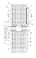
本発明の実施形態にかかる基板搬送装置とそれを用いた基板検査システムを以下に説明する。図1は、本発明の実施形態に係る基板搬送装置1とそれを用いた基板検査システム100の概要を示す平面図である。この図において二点鎖線は基板Wの大きさを示す。基板検査システム100は、基板搬送装置1と、その基板搬送装置1によって搬送される基板Wの表面を撮像する撮像装置2と、その撮像装置2によって撮像された画像を検査する検査装置3と、その検査装置3による検査結果を表示する表示装置4とから構成される。
A substrate transfer apparatus according to an embodiment of the present invention and a substrate inspection system using the same will be described below. FIG. 1 is a plan view showing an outline of a
基板搬送装置1の前工程の装置は図1中では右側に配置され、その前工程装置の一部であるローラコンベア5から基板Wが搬出される。基板搬送装置1は、前記前工程装置のローラコンベア5と連なって配置され、そのローラコンベア5から基板Wを受け入れるとともに、後述のように後工程装置のローラコンベア6へ基板Wを受け渡すローラコンベア7と、そのローラコンベア7で受け入れた基板Wに対して下方からエアを吹き付けてわずかに浮上させる浮上ステージ8と、その浮上ステージ8に沿って移動可能に設けられ、上の前記基板の裏面側のいずれかの側縁部を吸着する吸着部9を有する移動機構10とを有する。
The apparatus for the pre-process of the
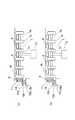
図2は基板搬送装置1の模式的側面図である。ローラコンベア7は、所定の高さに平行に設けられた複数の回転軸7aのそれぞれに、所定の間隔をもってローラ7bを取り付け、その各回転軸7aに図示しないモータや駆動ベルト等の駆動源を設けて構成される。また全ての回転軸7aは共通の軸受け部材7cを介して連結支持され、エアシリンダ等の昇降駆動源7dの駆動により昇降可能に支持されている。
FIG. 2 is a schematic side view of the
浮上ステージ8は、ローラコンベア7の隣り合うローラ7bの間に、基板Wの搬送方向に長く、複数の回転軸7aにまたがるように設けられ、その上面に気体の吹き出し口8aが形成され、また図示しない気体供給装置に接続されている。浮上ステージ8の上面は、上述した昇降駆動源7dによってローラコンベア7が上昇した際にはローラ7bの方が高く、またローラコンベア7が下降した際には浮上ステージ8の上面のほうが高い位置に設置固定されている。
The
移動機構10は、ローラコンベア7に沿ってその側方に設けられた直動案内部材10aと、その直動案内部材10a上を移動する移動部10bとからなるリニアモータ10cを備え、移動台10dは移動部10bに取り付け固定されている。移動台10dは、基板Wの搬送方向すなわち直動案内部材10aの方向に基板Wとほぼ匹敵する長さを有し、その上面には、ローラコンベア7に支持されている基板Wの裏面側すなわちすなわち下面側を下方から真空吸着する吸着部9が取り付け固定されている。吸着部9はその上端が浮上ステージ8の上面とほぼ同じか、または吸着部9のほうが若干高いがローラ7bの上端よりは低い位置になるように上向きに開口し、その長さは基板Wの長さよりも若干短く、図示しない真空吸着源や開閉バルブ等に配管を介して接続され、基板Wを下方から吸着して固定し、移動させることができる。
The
移動機構10の移動台10dには、さらに、吸着部9の近傍に、基板Wの裏面側すなわち下面側の側縁部を吸着する補助吸着部11が設けられている。補助吸着部11はエアシリンダ等の昇降機構12に取り付けられて上下移動可能であり、固定された吸着部9の上端の吸着面に対して上にある位置と、同じ高さの位置と、下にある位置との間を移動可能となっている。また補助吸着部11は吸着部9よりも基板W中心側から見て若干外側すなわち基板Wの端縁近くに位置しており、基板Wの裏面側の側縁に対して進退可能に設けられている。また、移動機構10、吸着部9、補助吸着部11およびその駆動のための昇降機構12は基板Wの搬送高さ(いわゆるパスライン)よりも低い位置に設けられているため、これらが原因で発生した塵埃が基板Wを汚染する可能性は低い。
The
撮像装置2は、ローラコンベア7と移動機構10の直動案内部材10aをまたぐように設けられた門形の支持部2aと、その支持部2aの上面に基板Wの搬送方向と交差する方向に設けられた直動案内部材2bと、その直動案内部材2b上を図示しない駆動源によって移動する移動台2cと、その移動台2c上に設けられたカメラ2dとからなる。カメラ2dは移動台2cの移動により基板Wの搬送方向と直交する方向に走査されながら、支持部2aの下方を通過する基板Wの表面を撮像する。カメラ2dとからなる。
The
検査装置3は、いわゆるマイクロコンピュータよりなり、撮像装置2のカメラ2dが撮像した基板Wの表面の画像を入力し、その表面の欠陥の有無等を検査するものである。また検査装置3のマイクロコンピュータは、ローラコンベア7や昇降駆動源7d、浮上ステージ8、移動機構10などの基板搬送装置1の駆動や、撮像装置2の全体の動作も制御する。表示装置4は検査装置3による検査結果を表示する。
The inspection device 3 is formed of a so-called microcomputer, and inputs an image of the surface of the substrate W imaged by the
〔基板検査システムの動作〕 [Operation of PCB inspection system]
次に、上記基板検査システム100の動作を説明する。基板検査システム100は、前工程装置のローラコンベア5から基板Wを受け入れる際には、基板搬送装置1の昇降駆動源7dによってローラコンベア7のローラ7bが上昇した位置にあり、また補助吸着部11は昇降機構12により吸着部9の上端の吸着面に対して下にある位置の状態とされる。このとき、ローラコンベア7に基板Wが搬送されてくると、図2(a)に示す状態となる。このとき、基板Wに反りが発生していない場合には、図2(a)に示す状態から、昇降駆動源7dによってローラコンベア7のローラ7bを下降させる。これにより基板Wは図2(b)に示すようにローラコンベア7のローラ7bから浮上ステージ8に受け渡され、基板は浮上ステージ8の吹き出し口8aから吹き出す気体によって微小に浮き上がった常態で支持されるとともに、吸着部9によって吸着して固定される。そしてこの状態で移動機構10を駆動して移動台10dを移動させることにより、移動台10dとともに移動する吸着部9に吸着されている基板Wは、搬送方向すなわち撮像装置2の方向に搬送され、撮像装置2の門形の支持部2aの下を通って後工程装置側へ搬送されてゆく。そしてその支持部2aの下方を通過する際に、その上面に設置されているカメラ2dが基板Wの移動方向と直交する方向に走査しながら基板Wの表面を撮像する。カメラ2dが撮像した画像は検査装置3に入力され、その表面の欠陥の有無等が検査される。欠陥の有無等の検査結果は表示装置4に表示され、また必要に応じ後工程装置側へも伝達される。基板Wの全体が撮像装置2の下方を通過して図1中の撮像装置2の左側に移動し検査が終了すると、吸着部9による基板Wの吸着固定を解除するとともに昇降駆動源7dを駆動してローラコンベア7を上昇させ、基板Wをローラコンベア7のローラ7bで保持する。そしてローラコンベア7を駆動して基板Wを後工程装置のローラコンベア6へ搬出する。
Next, the operation of the substrate inspection system 100 will be described. When the substrate inspection system 100 receives the substrate W from the
次に、上記基板検査システム100に搬送されてきた基板Wの側縁部に反りがある場合の動作を説明する。基板検査システム100に基板Wが搬送されて浮上ステージ8に受け渡されたときに、基板Wの移動機構10がある側に反りがあると、図3(a)に示すように基板Wの側縁が上方に反ってしまっているために、移動機構10の吸着部9が基板Wの側縁を吸着することができない。吸着部9が基板Wを吸着できなかったことは、吸着部9に真空吸着源や開閉バルブを接続している配管内にセンサを設けてその圧力や風速等を計測してその結果を検査装置3のマイクロコンピュータに入力して検出される。
Next, an operation when the side edge portion of the substrate W that has been transported to the substrate inspection system 100 is warped will be described. When the substrate W is transported to the substrate inspection system 100 and transferred to the floating
図3(a)の状態が検出されると、マイクロコンピュータは昇降機構12を駆動して補助吸着部11を上昇させ、その補助吸着部11により基板Wの側縁を吸着する。このとき、補助吸着部11の先端には、基板Wの反りによる基板面の傾斜(図3(a)(b)中では左側端部が高い)に倣うようにその先端を首振りして傾斜させる倣い機構が設けられており、反りで傾斜した基板Wを確実に吸着できる。
When the state shown in FIG. 3A is detected, the microcomputer drives the elevating
補助吸着部11が基板Wを吸着すると、その吸着を保ったまま昇降機構12を駆動して補助吸着部11を下降させ、図3(c)に示すように基板Wが吸着部9の高さになるように基板Wの反った側縁部を引き下げて、吸着部9が基板Wを吸着できるようにする。そして吸着部9が基板Wを吸着したことを検出すると、補助吸着部11の吸着を解除し、図3(d)に示すようにさらに下降する。これで吸着部9による基板Wの吸着ができたので、以後は同様に基板Wの表面検査を行うことができる。
When the
〔変形例〕 [Modification]
上記実施形態では、補助吸着部11は移動台10dに設けられているが、基板wの搬送開始箇所のみで補助吸着部11を使用するのであれば、補助吸着部11を移動台10d上に設けることは必ずしも必要ではなく、ローラコンベア7の基板Wの搬入位置近傍に固定的に設けてもよいが、基板Wの反りの力に逆らって基板Wを確実に吸着部9に引き付けるためには、吸着部9よりも基板Wの端縁側に設けることが望ましい。
In the above embodiment, the
また、基板Wの裏面に対して進退可能に設ける吸着機構が、基板Wの搬送に十分な吸着力があれば、吸着部9と補助吸着部11とを別に設ける必要はなく、移動台10dに1つの吸着機構を進退可能に設けることもできる。この場合、基板Wが反っているときにはその吸着機構を昇降させて基板W裏面の吸着を行い、その吸着機構で基板Wを吸着したまま移動台10dを移動させて基板Wを搬送すればよい。
Further, if the suction mechanism provided so as to be able to advance and retreat with respect to the back surface of the substrate W has a sufficient suction force for transporting the substrate W, it is not necessary to separately provide the
また、リニアモータ10cに代えてボールネジ等の周知の駆動源を用いてもよい。
A known drive source such as a ball screw may be used instead of the
100 基板検査システム
1 基板搬送装置
2 撮像装置
3 検査装置
7 ローラコンベア
8 浮上ステージ
9 吸着部
10 移動機構
10c リニアモータ
10d 移動台
11 補助吸着部
12 昇降機構
DESCRIPTION OF SYMBOLS 100 Board |
Claims (6)
前記ステージに沿って移動可能に設けられ、上の前記基板の裏面側のいずれかの側縁部を吸着する吸着部を有する移動機構と、
前記吸着部近傍において前記前記基板の裏面側の前記側縁部に対して進退可能に設けられ、前記基板の側縁部を吸着して前記吸着部に引き付ける補助吸着部と、
を備えたことを特徴とする基板搬送装置。 A stage for floating the substrate;
A moving mechanism that is provided movably along the stage and has a suction part that sucks any side edge of the back side of the substrate;
An auxiliary suction part that is provided so as to be able to advance and retreat with respect to the side edge part on the back surface side of the substrate in the vicinity of the suction part, and that attracts the side edge part of the substrate and attracts it to the suction part;
A substrate transfer device comprising:
前記補助吸着部は前記吸着部よりも基板の端縁側に設けられていることを特徴とする基板搬送装置。 The substrate transfer apparatus according to claim 1, wherein
The substrate transporting apparatus, wherein the auxiliary suction unit is provided closer to an edge of the substrate than the suction unit.
前記移動機構は、前記ステージに沿って移動可能でかつ前記吸着部を備えた移動台を有し、
前記補助吸着部は前記移動台に設けられていることを特徴とする基板搬送装置。 In the board | substrate conveyance apparatus of Claim 1 or 2,
The moving mechanism has a moving table that is movable along the stage and includes the suction portion;
The substrate transfer apparatus, wherein the auxiliary suction unit is provided on the movable table.
前記補助吸着部は、先端の吸着口近傍に、前記基板の周縁部の反りによる基板面の傾斜に倣う倣い部を備えたことを特徴とする基板搬送装置。 In the board | substrate conveyance apparatus in any one of Claims 1 thru | or 3,
The substrate transporting apparatus, wherein the auxiliary suction part includes a copying part that follows the inclination of the substrate surface due to the warp of the peripheral part of the substrate in the vicinity of the suction port at the tip.
前記ステージに沿って移動可能に設けられ、上の前記基板の裏面側のいずれかの側縁部を固定する固定部を有し、基板を移動させる移動機構とを備え、
前記固定部は、前記移動機構の移動台に設けられ、前記前記基板の裏面側の前記側縁部に対して進退可能に設けられて前記基板の側縁部を吸着する吸着機構よりなることを特徴とする基板搬送装置。 A stage for floating the substrate;
A movable mechanism that is provided movably along the stage, has a fixing portion that fixes any side edge of the back side of the upper substrate, and has a moving mechanism that moves the substrate;
The fixed portion is provided on a moving base of the moving mechanism, and is provided with an adsorbing mechanism that is provided so as to be able to advance and retreat with respect to the side edge on the back surface side of the substrate and adsorbs the side edge of the substrate. A substrate transfer device.
当該基板搬送装置に搬送される基板の表面を撮像する撮像装置と、
その撮像装置によって撮像された画像を検査する検査装置と、
を備えたことを特徴とする基板検査システム。 A substrate transfer apparatus according to any one of claims 1 to 5;
An imaging device for imaging the surface of the substrate conveyed to the substrate conveyance device;
An inspection apparatus for inspecting an image captured by the imaging apparatus;
A board inspection system comprising:
Priority Applications (1)
| Application Number | Priority Date | Filing Date | Title |
|---|---|---|---|
| JP2010067267A JP2011199218A (en) | 2010-03-24 | 2010-03-24 | Substrate conveyance device and substrate inspection system using the same |
Applications Claiming Priority (1)
| Application Number | Priority Date | Filing Date | Title |
|---|---|---|---|
| JP2010067267A JP2011199218A (en) | 2010-03-24 | 2010-03-24 | Substrate conveyance device and substrate inspection system using the same |
Publications (1)
| Publication Number | Publication Date |
|---|---|
| JP2011199218A true JP2011199218A (en) | 2011-10-06 |
Family
ID=44877007
Family Applications (1)
| Application Number | Title | Priority Date | Filing Date |
|---|---|---|---|
| JP2010067267A Abandoned JP2011199218A (en) | 2010-03-24 | 2010-03-24 | Substrate conveyance device and substrate inspection system using the same |
Country Status (1)
| Country | Link |
|---|---|
| JP (1) | JP2011199218A (en) |
Cited By (4)
| Publication number | Priority date | Publication date | Assignee | Title |
|---|---|---|---|---|
| JP2013152141A (en) * | 2012-01-25 | 2013-08-08 | Nippon Electric Glass Co Ltd | Glass plate edge inspection device |
| CN103247509A (en) * | 2012-02-08 | 2013-08-14 | 北京北方微电子基地设备工艺研究中心有限责任公司 | Plasma processing equipment |
| WO2016198159A1 (en) * | 2015-06-12 | 2016-12-15 | Durst Phototechnik Digital Technology Gmbh | Transport system for an inkjet printer |
| CN109484794A (en) * | 2017-09-13 | 2019-03-19 | 京东方科技集团股份有限公司 | A kind of base plate transfer device |
Citations (5)
| Publication number | Priority date | Publication date | Assignee | Title |
|---|---|---|---|---|
| JP2004179399A (en) * | 2002-11-27 | 2004-06-24 | Seiko Epson Corp | Method and apparatus for fixing substrate, printing apparatus, and manufacturing method of display |
| JP2006188313A (en) * | 2005-01-04 | 2006-07-20 | Olympus Corp | Substrate conveying device and substrate inspection device |
| JP2008063020A (en) * | 2006-09-04 | 2008-03-21 | Olympus Corp | Substrate carrying device, and substrate inspection system using it |
| JP2008235472A (en) * | 2007-03-19 | 2008-10-02 | Dainippon Screen Mfg Co Ltd | Substrate treatment apparatus |
| JP2010058869A (en) * | 2008-09-01 | 2010-03-18 | Fujifilm Corp | Film separation device and method |
-
2010
- 2010-03-24 JP JP2010067267A patent/JP2011199218A/en not_active Abandoned
Patent Citations (5)
| Publication number | Priority date | Publication date | Assignee | Title |
|---|---|---|---|---|
| JP2004179399A (en) * | 2002-11-27 | 2004-06-24 | Seiko Epson Corp | Method and apparatus for fixing substrate, printing apparatus, and manufacturing method of display |
| JP2006188313A (en) * | 2005-01-04 | 2006-07-20 | Olympus Corp | Substrate conveying device and substrate inspection device |
| JP2008063020A (en) * | 2006-09-04 | 2008-03-21 | Olympus Corp | Substrate carrying device, and substrate inspection system using it |
| JP2008235472A (en) * | 2007-03-19 | 2008-10-02 | Dainippon Screen Mfg Co Ltd | Substrate treatment apparatus |
| JP2010058869A (en) * | 2008-09-01 | 2010-03-18 | Fujifilm Corp | Film separation device and method |
Cited By (5)
| Publication number | Priority date | Publication date | Assignee | Title |
|---|---|---|---|---|
| JP2013152141A (en) * | 2012-01-25 | 2013-08-08 | Nippon Electric Glass Co Ltd | Glass plate edge inspection device |
| CN103247509A (en) * | 2012-02-08 | 2013-08-14 | 北京北方微电子基地设备工艺研究中心有限责任公司 | Plasma processing equipment |
| WO2016198159A1 (en) * | 2015-06-12 | 2016-12-15 | Durst Phototechnik Digital Technology Gmbh | Transport system for an inkjet printer |
| CN109484794A (en) * | 2017-09-13 | 2019-03-19 | 京东方科技集团股份有限公司 | A kind of base plate transfer device |
| US11230436B2 (en) | 2017-09-13 | 2022-01-25 | Boe Technology Group Co., Ltd. | Substrate conveyance device |
Similar Documents
| Publication | Publication Date | Title |
|---|---|---|
| JP4896112B2 (en) | Substrate transfer device | |
| JP5001681B2 (en) | Inline automatic inspection device and inline automatic inspection system | |
| TW200906695A (en) | Substrate adsorption device, substrate transportation device and external inspection equipment | |
| TWI393878B (en) | Panel inspection device and inspection method of panel | |
| JP2009075102A (en) | Inspection device and inspection method | |
| CN107534009A (en) | Substrate conveyance robot and substrate inspecting method | |
| JP2012094711A (en) | Inspection equipment | |
| JP2007112626A (en) | Substrate carrying device, substrate inspection device and substrate carrying method | |
| JP2007248291A (en) | Substrate inspecting apparatus | |
| JP2011199218A (en) | Substrate conveyance device and substrate inspection system using the same | |
| JP2008159784A (en) | Stage apparatus | |
| JP5005945B2 (en) | Board inspection equipment | |
| TWI746589B (en) | Substrate breaking system | |
| WO2018139244A1 (en) | Alignment device | |
| TWI707130B (en) | Carrier device, optical inspection apparatus and optical inspection method | |
| KR20150068575A (en) | Board grip and carrying device and method for using thereof | |
| JP4704756B2 (en) | Substrate transfer device | |
| JP2009022823A (en) | Inspection apparatus and substrate treatment system | |
| KR101669992B1 (en) | apparatus for inspecting both sides of substrate | |
| JP5426416B2 (en) | Substrate transport apparatus, substrate transport method, and imaging apparatus | |
| KR100837436B1 (en) | Apparatus for inspection and measurement of substrate | |
| KR101318212B1 (en) | Carrying apparatus of glass | |
| JP5928771B2 (en) | Substrate inspection apparatus and substrate inspection method | |
| JP2012017183A (en) | Substrate transfer apparatus | |
| JP2004333198A (en) | Substrate inspection apparatus |
Legal Events
| Date | Code | Title | Description |
|---|---|---|---|
| A621 | Written request for application examination |
Free format text: JAPANESE INTERMEDIATE CODE: A621 Effective date: 20120323 |
|
| RD03 | Notification of appointment of power of attorney |
Free format text: JAPANESE INTERMEDIATE CODE: A7423 Effective date: 20120323 |
|
| A977 | Report on retrieval |
Free format text: JAPANESE INTERMEDIATE CODE: A971007 Effective date: 20130417 |
|
| A131 | Notification of reasons for refusal |
Free format text: JAPANESE INTERMEDIATE CODE: A131 Effective date: 20130423 |
|
| A762 | Written abandonment of application |
Free format text: JAPANESE INTERMEDIATE CODE: A762 Effective date: 20130531 |