JP2011190833A - 止水方法および止水装置 - Google Patents
止水方法および止水装置 Download PDFInfo
- Publication number
- JP2011190833A JP2011190833A JP2010055629A JP2010055629A JP2011190833A JP 2011190833 A JP2011190833 A JP 2011190833A JP 2010055629 A JP2010055629 A JP 2010055629A JP 2010055629 A JP2010055629 A JP 2010055629A JP 2011190833 A JP2011190833 A JP 2011190833A
- Authority
- JP
- Japan
- Prior art keywords
- water
- water stop
- bag
- stopping
- fluid
- Prior art date
- Legal status (The legal status is an assumption and is not a legal conclusion. Google has not performed a legal analysis and makes no representation as to the accuracy of the status listed.)
- Pending
Links
- XLYOFNOQVPJJNP-UHFFFAOYSA-N water Substances O XLYOFNOQVPJJNP-UHFFFAOYSA-N 0.000 title claims abstract description 191
- 238000000034 method Methods 0.000 title claims abstract description 22
- 238000007789 sealing Methods 0.000 claims abstract description 23
- 239000012530 fluid Substances 0.000 claims description 43
- 239000007788 liquid Substances 0.000 claims description 13
- 230000000903 blocking effect Effects 0.000 description 9
- 230000005540 biological transmission Effects 0.000 description 7
- 150000001875 compounds Chemical class 0.000 description 4
- 239000000203 mixture Substances 0.000 description 4
- 238000005192 partition Methods 0.000 description 4
- 238000004078 waterproofing Methods 0.000 description 4
- 238000005086 pumping Methods 0.000 description 3
- 238000012986 modification Methods 0.000 description 2
- 230000004048 modification Effects 0.000 description 2
- 238000012545 processing Methods 0.000 description 2
- 238000005452 bending Methods 0.000 description 1
- 238000007796 conventional method Methods 0.000 description 1
- 238000013461 design Methods 0.000 description 1
- 238000005538 encapsulation Methods 0.000 description 1
- 238000002347 injection Methods 0.000 description 1
- 239000007924 injection Substances 0.000 description 1
- 239000000463 material Substances 0.000 description 1
- 230000002093 peripheral effect Effects 0.000 description 1
- 239000000126 substance Substances 0.000 description 1
- 230000003746 surface roughness Effects 0.000 description 1
- 230000008961 swelling Effects 0.000 description 1
Images

Landscapes
- Underground Structures, Protecting, Testing And Restoring Foundations (AREA)
Abstract
【解決手段】 管路2と電力ケーブル3との間に、内圧によって膨出可能な止水袋4を配置し、止水袋4内にゲル5を圧送するとともに、圧送されたゲル5を止水袋4内に封入し、ゲル5の封入によって膨出した止水袋4を管路2と電力ケーブル3の双方に密着させる。
【選択図】 図1
Description
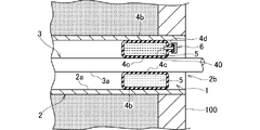
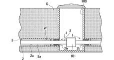
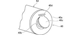
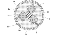
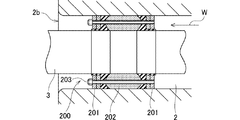
図1ないし図5は、本発明の実施の形態1を示しており、特に地中送電線路のマンホール100に適用した場合を示している。図2に示すように、地中Gに埋設された左右の管路2の端部は、マンホール100の下部側に接続されている。各管路2内に敷設された電力ケーブル(単相電力ケーブル)3は、マンホール100内まで延びており、この電力ケーブル3同士はマンホール100の下部に設けられた接続箱101内で接続されている。各管路2のマンホール100への開口部2bには、地中Gから管路2内に浸入した水Wのマンホール100への流入を防止する止水装置1が設けられている。
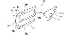
図6および図7は、本発明の実施の形態2を示している。実施の形態2が実施の形態1と異なるところは、管路2を通る電力ケーブル3の本数であり、その他の部分は実施の形態1に準じるので、準じる部分については実施の形態1と同一の符号を付すことにより、その説明を省略する。後述する他の実施の形態も同様とする。
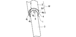
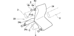
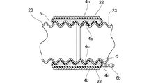
図9および図10は、本発明の実施の形態3を示しており、止水装置1をフレックス管の接続に適用した場合を示している。図10に示すように、第1の部材としての止水用パイプ22および第2の部材としてのフレックス管23は、接続後に地中に埋設されるようになっている。左右のフレックス管23の端部は、止水用パイプ22の内側に配置されている。フレックス管23は、上下および左右方向に屈曲可能であり、縦断面形状が波形をしている。すなわち、フレックス管23の外面は凹凸面に形成されている。止水装置1の止水袋4の膨出量は、例えば30mmに設定されている。
2 管路(第1の部材)
3 電力ケーブル(第2の部材)
4 止水袋
4b 第1の押圧部
4c 第2の押圧部
5 ゲル(止水用流体)
6 流体封入手段
20 止水装置
22 止水用パイプ(第1の部材)
23 フレックス管(第2の部材)
24 止水袋
24b 第1の押圧部
24c 第2の押圧部
40 逆止弁
Claims (6)
- 第1の部材と第2の部材との間からの液漏れを防止する止水方法であって、前記第1の部材と前記第2の部材との間に、内圧によって膨出可能な止水袋を配置し、前記止水袋内に止水用流体を圧送するとともに、圧送された止水用流体を前記止水袋内に封入し、前記止水用流体の封入によって膨出した前記止水袋を前記第1の部材と前記第2の部材の双方に密着させることを特徴とする止水方法。
- 第1の部材と第2の部材との間からの液漏れを防止する止水装置であって、
前記第1の部材と前記第2の部材との間に配置可能で内圧によって膨出可能な止水袋と、
前記止水袋内に圧送された止水用流体を前記止水袋内に封入する流体封入手段と、
を備え、
前記止水袋は、前記止水用流体の封入による膨出によって前記第1の部材と前記第2の部材の双方に密着可能であることを特徴とする止水装置。 - 前記止水用流体は、少なくとも水、空気、ゲルのいずれかであることを特徴とする請求項1に記載の止水方法または請求項2に記載の止水装置。
- 前記止水袋の前記止水用流体の流入口には、前記止水用流体の前記止水袋への流入を許容するとともに、前記止水用流体の前記止水袋からの流出を阻止する逆止弁が設けられていることを特徴とする請求項2に記載の止水装置。
- 前記第1の部材は地中に埋設されマンホールと接続される管路であり、前記第2の部材は前記管路内に敷設される電力ケーブルである、ことを特徴とする請求項1に記載の止水方法または請求項2に記載の止水装置。
- 前記第1の部材は地中に埋設される止水用パイプであり、前記第2の部材は少なくとも前記止水用パイプの内側に配置され地中に埋設されるフレックス管、異径管、異種管のいずれかである、ことを特徴とする請求項1に記載の止水方法または請求項2に記載の止水装置。
Priority Applications (1)
| Application Number | Priority Date | Filing Date | Title |
|---|---|---|---|
| JP2010055629A JP2011190833A (ja) | 2010-03-12 | 2010-03-12 | 止水方法および止水装置 |
Applications Claiming Priority (1)
| Application Number | Priority Date | Filing Date | Title |
|---|---|---|---|
| JP2010055629A JP2011190833A (ja) | 2010-03-12 | 2010-03-12 | 止水方法および止水装置 |
Publications (1)
| Publication Number | Publication Date |
|---|---|
| JP2011190833A true JP2011190833A (ja) | 2011-09-29 |
Family
ID=44795973
Family Applications (1)
| Application Number | Title | Priority Date | Filing Date |
|---|---|---|---|
| JP2010055629A Pending JP2011190833A (ja) | 2010-03-12 | 2010-03-12 | 止水方法および止水装置 |
Country Status (1)
| Country | Link |
|---|---|
| JP (1) | JP2011190833A (ja) |
Cited By (2)
| Publication number | Priority date | Publication date | Assignee | Title |
|---|---|---|---|---|
| KR101738539B1 (ko) | 2016-02-29 | 2017-05-22 | 우주환경건설 주식회사 | 노후 하수관로 비굴착 전체 보수 보강공법 및 장치 |
| KR20170121755A (ko) * | 2016-04-25 | 2017-11-03 | 한국전력공사 | 관로구 방수장치 |
Citations (2)
| Publication number | Priority date | Publication date | Assignee | Title |
|---|---|---|---|---|
| JPS5762713A (en) * | 1980-09-30 | 1982-04-15 | Tadao Hanaoka | Waterproof device for buried cable protecting tube end |
| JPH08501138A (ja) * | 1992-09-04 | 1996-02-06 | エヌ・ヴェ・レイケム・ソシエテ・アノニム | 周囲シーリング |
-
2010
- 2010-03-12 JP JP2010055629A patent/JP2011190833A/ja active Pending
Patent Citations (2)
| Publication number | Priority date | Publication date | Assignee | Title |
|---|---|---|---|---|
| JPS5762713A (en) * | 1980-09-30 | 1982-04-15 | Tadao Hanaoka | Waterproof device for buried cable protecting tube end |
| JPH08501138A (ja) * | 1992-09-04 | 1996-02-06 | エヌ・ヴェ・レイケム・ソシエテ・アノニム | 周囲シーリング |
Cited By (3)
| Publication number | Priority date | Publication date | Assignee | Title |
|---|---|---|---|---|
| KR101738539B1 (ko) | 2016-02-29 | 2017-05-22 | 우주환경건설 주식회사 | 노후 하수관로 비굴착 전체 보수 보강공법 및 장치 |
| KR20170121755A (ko) * | 2016-04-25 | 2017-11-03 | 한국전력공사 | 관로구 방수장치 |
| KR102521050B1 (ko) * | 2016-04-25 | 2023-04-14 | 한국전력공사 | 관로구 방수장치 |
Similar Documents
| Publication | Publication Date | Title |
|---|---|---|
| US5353842A (en) | Inflatable plug for use in plugging a large diameter pipe | |
| AU2015203930B2 (en) | Method and apparatus for lining a pipe | |
| CN111155625B (zh) | 检查井 | |
| JP2011190833A (ja) | 止水方法および止水装置 | |
| TW312652B (en) | The construction method for lining the pipe | |
| JP4948081B2 (ja) | 水圧試験装置 | |
| CN107975652B (zh) | 管维修工具 | |
| KR102521050B1 (ko) | 관로구 방수장치 | |
| JP2016180596A (ja) | 水密試験装置及びその水密試験装置を用いた水密試験方法 | |
| JP2022110386A (ja) | マンホールの下水バイパス装置用止水プラグ | |
| KR100637586B1 (ko) | 상,하수도관로의 보수-보강장치 및 방법 | |
| KR102847710B1 (ko) | 다양한 규격의 관로에 적용 가능한 관로 부분 보수장치 및 이를 이용한 관로 부분 보수공법 | |
| JP3117923B2 (ja) | 内張りライニング用反転装置 | |
| KR200333419Y1 (ko) | 유체 저장조의 누수 및 누설 방지 연결 장치 | |
| KR101513849B1 (ko) | 배관 연결부 밀봉 구조 | |
| KR101246779B1 (ko) | 누설 방지 기능을 가진 보수액 주입 장치 | |
| KR100885023B1 (ko) | 액압잭 장치 및 그의 제조방법 | |
| CN212131611U (zh) | 一种混凝土顶管 | |
| WO2011036125A1 (en) | Apparatus and method for lining a conduit | |
| US12092256B2 (en) | Pressurized push rod system and device | |
| CN107542982A (zh) | 一种直插式管道连接装置 | |
| AU2018232892B2 (en) | Device and method for repairing pipe | |
| RU89657U1 (ru) | Резьбовое соединение для труб | |
| JPH06249363A (ja) | 内挿接続管装置 | |
| RU2627812C2 (ru) | Устройство для ремонта изгибных участков трубопровода (варианты) |
Legal Events
| Date | Code | Title | Description |
|---|---|---|---|
| A977 | Report on retrieval |
Free format text: JAPANESE INTERMEDIATE CODE: A971007 Effective date: 20120625 |
|
| A131 | Notification of reasons for refusal |
Free format text: JAPANESE INTERMEDIATE CODE: A131 Effective date: 20120703 |
|
| A521 | Written amendment |
Free format text: JAPANESE INTERMEDIATE CODE: A523 Effective date: 20120810 |
|
| A131 | Notification of reasons for refusal |
Free format text: JAPANESE INTERMEDIATE CODE: A131 Effective date: 20121016 |
|
| A521 | Written amendment |
Free format text: JAPANESE INTERMEDIATE CODE: A523 Effective date: 20121205 |
|
| A02 | Decision of refusal |
Free format text: JAPANESE INTERMEDIATE CODE: A02 Effective date: 20130625 |