JP2011129901A - Method of manufacturing semiconductor light emitting device - Google Patents
Method of manufacturing semiconductor light emitting device Download PDFInfo
- Publication number
- JP2011129901A JP2011129901A JP2010258986A JP2010258986A JP2011129901A JP 2011129901 A JP2011129901 A JP 2011129901A JP 2010258986 A JP2010258986 A JP 2010258986A JP 2010258986 A JP2010258986 A JP 2010258986A JP 2011129901 A JP2011129901 A JP 2011129901A
- Authority
- JP
- Japan
- Prior art keywords
- light emitting
- semiconductor light
- emitting device
- curable resin
- ultraviolet curable
- Prior art date
- Legal status (The legal status is an assumption and is not a legal conclusion. Google has not performed a legal analysis and makes no representation as to the accuracy of the status listed.)
- Pending
Links
Images


Classifications
-
- H—ELECTRICITY
- H01—ELECTRIC ELEMENTS
- H01L—SEMICONDUCTOR DEVICES NOT COVERED BY CLASS H10
- H01L2224/00—Indexing scheme for arrangements for connecting or disconnecting semiconductor or solid-state bodies and methods related thereto as covered by H01L24/00
- H01L2224/01—Means for bonding being attached to, or being formed on, the surface to be connected, e.g. chip-to-package, die-attach, "first-level" interconnects; Manufacturing methods related thereto
- H01L2224/42—Wire connectors; Manufacturing methods related thereto
- H01L2224/47—Structure, shape, material or disposition of the wire connectors after the connecting process
- H01L2224/48—Structure, shape, material or disposition of the wire connectors after the connecting process of an individual wire connector
- H01L2224/4805—Shape
- H01L2224/4809—Loop shape
- H01L2224/48091—Arched
-
- H—ELECTRICITY
- H01—ELECTRIC ELEMENTS
- H01L—SEMICONDUCTOR DEVICES NOT COVERED BY CLASS H10
- H01L2224/00—Indexing scheme for arrangements for connecting or disconnecting semiconductor or solid-state bodies and methods related thereto as covered by H01L24/00
- H01L2224/01—Means for bonding being attached to, or being formed on, the surface to be connected, e.g. chip-to-package, die-attach, "first-level" interconnects; Manufacturing methods related thereto
- H01L2224/42—Wire connectors; Manufacturing methods related thereto
- H01L2224/47—Structure, shape, material or disposition of the wire connectors after the connecting process
- H01L2224/49—Structure, shape, material or disposition of the wire connectors after the connecting process of a plurality of wire connectors
- H01L2224/491—Disposition
- H01L2224/49105—Connecting at different heights
- H01L2224/49107—Connecting at different heights on the semiconductor or solid-state body
-
- H—ELECTRICITY
- H01—ELECTRIC ELEMENTS
- H01L—SEMICONDUCTOR DEVICES NOT COVERED BY CLASS H10
- H01L2224/00—Indexing scheme for arrangements for connecting or disconnecting semiconductor or solid-state bodies and methods related thereto as covered by H01L24/00
- H01L2224/80—Methods for connecting semiconductor or other solid state bodies using means for bonding being attached to, or being formed on, the surface to be connected
- H01L2224/85—Methods for connecting semiconductor or other solid state bodies using means for bonding being attached to, or being formed on, the surface to be connected using a wire connector
- H01L2224/85909—Post-treatment of the connector or wire bonding area
- H01L2224/8592—Applying permanent coating, e.g. protective coating
Abstract
Description
本発明は、封止材(encapsulating material)またはパッケージ材料として紫外線硬
化性樹脂を用いた半導体発光装置の製造方法に関する。より詳しくは、本発明は、紫外線と適度な熱とを併用して紫外線硬化性樹脂を硬化させて半導体発光素子を封止する、あるいは半導体発光素子を搭載するパッケージを作製する工程を有することを特徴とする耐熱性及び耐光性の高い半導体発光装置の製造方法に関する。
The present invention relates to a method for manufacturing a semiconductor light emitting device using an ultraviolet curable resin as an encapsulating material or a packaging material. More specifically, the present invention includes a step of sealing a semiconductor light emitting device by curing an ultraviolet curable resin using ultraviolet rays and appropriate heat in combination, or manufacturing a package on which the semiconductor light emitting device is mounted. The present invention relates to a method for manufacturing a semiconductor light emitting device having high heat resistance and high light resistance.
近年、発光ダイオード(LED)は各分野において利用されるが、中でも高輝度発光ダイオード(HBLED)は、極めて高いエネルギー効率を有し、特に照明用途に好適に使用される。一般に発光ダイオード装置(以下、「半導体発光装置」と称することがある。)は、通常、基材上に組み立てられたLEDチップ(以下、「半導体発光素子」と称することがある。)と、さらにそれを封止する材料(封止材)から成り、封止材はレンズの役割も担うことが多い。半導体発光素子の封止材として利用される材料の必要条件としては、光学透明度、高温耐性、UV耐性、高屈折率、及び種々の機械特性が挙げられ、用途や好みに応じて軟らかい材料から硬い材料まで種々使用される。上記の必要条件のレベルは、近年のHBLEDの開発により益々高くなっている。 In recent years, light-emitting diodes (LEDs) have been used in various fields. Among these, high-intensity light-emitting diodes (HBLEDs) have extremely high energy efficiency and are particularly suitable for lighting applications. In general, a light-emitting diode device (hereinafter sometimes referred to as “semiconductor light-emitting device”) is usually an LED chip (hereinafter also referred to as “semiconductor light-emitting element”) assembled on a substrate, and further. It consists of the material (sealing material) which seals it, and the sealing material often also plays the role of a lens. Necessary conditions for materials used as a sealing material for semiconductor light-emitting elements include optical transparency, high temperature resistance, UV resistance, high refractive index, and various mechanical properties. Various materials are used. The level of the above requirements has become higher and higher with the recent development of HBLEDs.
LED装置は、装置組み立て中(最大で260℃程度まで達する半田付け)及び実際の装置の作動中(一般的には約50℃〜100℃で数万時間)に高温状態に直面するので、半導体発光素子の封止材は、光学的に透明(90%以上の透過率)等の要件が必要とされ、さらに機械的及び光学的機能を低下させずに長時間高温に耐えることが要件とされる。
従来、半導体発光素子を封止する透明な樹脂としては、エポキシ樹脂が多用されてきた(特許文献1、2)。また、PMMA(ポリメチルメタクリレート)、ポリカーボネート、及び光学ナイロン(optical nylon)なども使用されている。しかしながら、このような
従来からある有機樹脂の光学特性は使用に際して経時的に低下してしまうという問題があった。特に、熱による劣化や短波長光の長時間照射によって黄変等の着色が生じる問題があった。このような劣化が進行すると封止材層から水分の侵入を引き起こし、半導体発光装置の性能劣化につながる虞もある。また、封止材の機械的な劣化は、基材のひび(cracking)、縮み(shrinking)又は薄層の裂け(delamination)も引き起こす。従って、封
止材としては軟らかいエラストマーであると同時にプラスチック様の硬さも有する材料系であることが望まれる。つまり、封止材は以下の性質を同時に備えることが要求される。(i)半導体発光装置を構成する部材のための機械的支持体として利用するのに充分に硬いこと(ii)装置の組み立て時に、半導体発光素子又は配線(wires)に対する損傷を防
ぐことができる程度に、また、温度の昇降時に、部材として使用する異なる熱膨張係数を有する各々の材料の膨張及び収縮の差によって剥離や割れが生じないように内部歪を和らげることができる程度に充分に軟らかくかつしなやかであること。
LED devices face high temperatures during device assembly (soldering up to about 260 ° C.) and during actual device operation (typically around 50 ° C. to 100 ° C. for tens of thousands of hours), so semiconductors The sealing material of the light emitting element is required to be optically transparent (transmittance of 90% or more) and the like, and further to withstand high temperatures for a long time without degrading mechanical and optical functions. The
Conventionally, an epoxy resin has been frequently used as a transparent resin for sealing a semiconductor light emitting device (Patent Documents 1 and 2). PMMA (polymethyl methacrylate), polycarbonate, optical nylon, and the like are also used. However, there has been a problem in that the optical properties of such conventional organic resins deteriorate over time during use. In particular, there is a problem that yellowing or other coloring occurs due to deterioration due to heat or irradiation with short wavelength light for a long time. When such deterioration proceeds, moisture may enter from the sealing material layer, which may lead to performance deterioration of the semiconductor light emitting device. Mechanical degradation of the encapsulant also causes cracking, shrinking or delamination of the substrate. Therefore, it is desirable that the sealing material be a material system that is a soft elastomer and also has a plastic-like hardness. That is, the sealing material is required to have the following properties at the same time. (I) It is hard enough to be used as a mechanical support for members constituting the semiconductor light emitting device. (Ii) To the extent that damage to the semiconductor light emitting elements or wires can be prevented during assembly of the device. In addition, when the temperature rises and falls, it is soft enough to soften the internal strain so that peeling or cracking does not occur due to the difference in expansion and contraction of each material having a different thermal expansion coefficient used as a member. Be supple.
一方、特許文献3には、透明性に優れ、経時による変色の少ない硬化物を与えるべき、発光ダイオード素子の保護材料、レンズ材料等としての適する紫外線硬化型シリコーン組成物が開示されている。
しかしながら、紫外線硬化型シリコーン組成物は以下の点で問題があった。即ち、半導体発光装置を構成するパッケージの形状によっては紫外線の当たりにくい箇所などが生じるため、硬化ムラが生じる問題があった。また、紫外線を吸収し易い蛍光体を使用した場合も、当該蛍光体の存否により硬化ムラが生じる問題があった。このような硬化ムラにより封止材内部に応力の差が生じ、パッケージから紫外線硬化型シリコーン組成物が剥離しやすいという問題もあった。また、特許文献3には耐光性に関する記載がなく、今般の高
出力・高輝度の半導体発光素子に使用できるとはいい難かった。
On the other hand, Patent Document 3 discloses an ultraviolet curable silicone composition suitable as a protective material for a light-emitting diode element, a lens material, etc., which should give a cured product having excellent transparency and little discoloration over time.
However, the ultraviolet curable silicone composition has the following problems. That is, depending on the shape of the package constituting the semiconductor light-emitting device, there are places where it is difficult for ultraviolet rays to hit, and thus there is a problem that uneven curing occurs. In addition, when a phosphor that easily absorbs ultraviolet rays is used, there is a problem that uneven curing occurs due to the presence or absence of the phosphor. Due to such unevenness of curing, a difference in stress occurs inside the sealing material, and there is also a problem that the ultraviolet curable silicone composition is easily peeled from the package. Further, Patent Document 3 has no description regarding light resistance, and it is difficult to say that it can be used for a high-power and high-brightness semiconductor light-emitting element.
上記のように、優れた光学透明性、高温耐性、紫外線耐性、高屈折率を有し、且つ種々の弾性特性を有する強健な半導体発光装置用の封止材、及びこのような封止材を用いて適切な半導体発光装置を製造する簡便な方法が求められている。本発明はこれを達成することを課題にするものである。 As described above, a sealing material for a robust semiconductor light-emitting device having excellent optical transparency, high temperature resistance, ultraviolet resistance, high refractive index, and various elastic characteristics, and such a sealing material. There is a need for a simple method of using and manufacturing a suitable semiconductor light emitting device. The present invention aims to achieve this.
本発明者らは鋭意検討の結果、紫外光〜可視光の波長領域で優れた光透過性、耐光性、耐熱性、湿熱耐性、及び紫外線耐性を有する特定の紫外線硬化性樹脂を用いた簡便な方法により、長期間使用しても亀裂及び剥離が生じない半導体発光装置を製造することができることを見出した。
また、本発明の半導体発光装置の製造方法により紫外線硬化性樹脂の硬化速度が速まり、種類の異なる蛍光体が、比重や形状の差によって硬化中に分離することを防ぐことが出来ることも見出した。
As a result of intensive studies, the present inventors have made simple use of a specific ultraviolet curable resin having excellent light transmission, light resistance, heat resistance, wet heat resistance, and ultraviolet resistance in the wavelength range of ultraviolet light to visible light. It has been found that the method can produce a semiconductor light emitting device that does not crack and peel even when used for a long time.
In addition, the method for manufacturing a semiconductor light emitting device of the present invention has also found that the curing rate of the ultraviolet curable resin is increased, and phosphors of different types can be prevented from being separated during curing due to a difference in specific gravity or shape. It was.
さらに、紫外線硬化樹脂を用いた上記の方法は半導体発光装置における半導体発光素子を搭載するパッケージ材料にも応用することができることを見出した。
すなわち、本発明は以下を特徴とする要旨を有するものである。
〔1〕 半導体発光素子を封止する工程を有する半導体発光装置の製造方法であって、前記半導体発光素子を封止する工程中、
(A)紫外線硬化性樹脂を50℃以上100℃以下の環境下で紫外線照射する工程を有し、前記紫外線硬化性樹脂の重量の15%以上が、珪素および珪素に隣接する酸素であることを特徴とする半導体発光装置の製造方法。
Furthermore, it has been found that the above-described method using an ultraviolet curable resin can be applied to a package material for mounting a semiconductor light emitting element in a semiconductor light emitting device.
That is, this invention has the summary characterized by the following.
[1] A method of manufacturing a semiconductor light emitting device including a step of sealing a semiconductor light emitting element, wherein the semiconductor light emitting element is sealed,
(A) A step of irradiating ultraviolet curable resin with ultraviolet rays in an environment of 50 ° C. or higher and 100 ° C. or lower, wherein 15% or more of the weight of the ultraviolet curable resin is silicon and oxygen adjacent to silicon. A method for manufacturing a semiconductor light emitting device.
〔2〕 半導体発光素子を搭載するパッケージを樹脂材料を用いて製造する工程を有する半導体発光装置の製造方法であって、前記パッケージを樹脂材料を用いて製造する工程中、
(A)紫外線性樹脂を50℃以上100℃以下の環境下で紫外線照射する工程を有し、前記紫外線硬化性樹脂の重量の15%以上が、珪素および珪素に隣接する酸素であることを特徴とする半導体発光装置の製造方法。
[2] A method of manufacturing a semiconductor light-emitting device including a step of manufacturing a package mounting a semiconductor light-emitting element using a resin material, wherein the package is manufactured using a resin material,
(A) It has a step of irradiating ultraviolet resin in an environment of 50 ° C. or more and 100 ° C. or less, and 15% or more of the weight of the ultraviolet curable resin is silicon and oxygen adjacent to silicon. A method for manufacturing a semiconductor light emitting device.
〔3〕 前記(A)工程の後に、(B)紫外線照射をしない状態で加熱する工程を有する前記〔1〕または〔2〕の半導体発光装置の製造方法。
〔4〕 前記(B)工程における加熱条件が、120℃以上、かつ5分以上である前記〔3〕の半導体発光装置の製造方法。
〔5〕 前記紫外線硬化性樹脂が、前記紫外線硬化性樹脂を60℃の環境下でピーク波長360nm、エネルギー量300mJ/m2で紫外線照射して厚さ2mmの硬化膜とした場合、下記の物性1および物性2の少なくとも1以上を有する前記〔1〕乃至〔4〕の半導体発光装置の製造方法。
[3] The method for manufacturing a semiconductor light-emitting device according to [1] or [2], further including a step (B) of heating without ultraviolet irradiation after the step (A).
[4] The method for manufacturing a semiconductor light-emitting device according to [3], wherein the heating condition in the step (B) is 120 ° C. or more and 5 minutes or more.
[5] When the ultraviolet curable resin is irradiated with ultraviolet rays at a peak wavelength of 360 nm and an energy amount of 300 mJ / m 2 in an environment of 60 ° C. to form a cured film having a thickness of 2 mm, the following physical properties are obtained: [1] to [4] The method for producing a semiconductor light emitting device according to any one of [1] to [4].
<物性1>
前記硬化膜を大気中150℃にて500時間保存した後の前記硬化膜のYI値が20.00以下であること
<物性2>
前記硬化膜を大気中室温にて350nm以上の波長の光を2100mW/cm2の強度で20時間照射した後の前記硬化膜のYI値が20.00以下であること
〔6〕 前記紫外線硬化性樹脂に、少なくともシリケート系、窒化物系、酸窒化物系、ガーネット系酸化物系のいずれかの物質を含む蛍光体を含有させる工程を有する前記〔1〕および〔3〕乃至〔5〕の半導体発光装置の製造方法。
<Physical property 1>
The YI value of the cured film after storing the cured film in the atmosphere at 150 ° C. for 500 hours is 20.00 or less <
The cured film has a YI value of 20.00 or less after being irradiated with light having a wavelength of 350 nm or more at room temperature in the atmosphere at an intensity of 2100 mW / cm 2 for 20 hours. The semiconductors according to [1] and [3] to [5] above, wherein the resin contains a phosphor containing at least one of a silicate, nitride, oxynitride, and garnet oxide substance. Manufacturing method of light-emitting device.
〔7〕前記半導体発光素子の発光ピーク波長が350nm以上500nm以下である前記〔1〕乃至〔6〕の半導体発光装置の製造方法。 [7] The method for manufacturing a semiconductor light emitting device according to any one of [1] to [6], wherein an emission peak wavelength of the semiconductor light emitting element is 350 nm or more and 500 nm or less.
本発明により、接着性、透明性、湿熱耐性及び紫外線耐性を有する紫外線硬化性樹脂を用いて、半導体発光素子の封止材や、半導体発光素子を搭載するパッケージとして優れた機能を有する半導体発光装置を製造することができる。 According to the present invention, a semiconductor light emitting device having an excellent function as a sealing material for a semiconductor light emitting element or a package for mounting a semiconductor light emitting element using an ultraviolet curable resin having adhesiveness, transparency, wet heat resistance and ultraviolet resistance Can be manufactured.
以下、本発明を詳細に説明するが、本発明は以下の実施の形態に限定されるものではなく、その要旨の範囲内であれば、種々に変更して実施することができる。
本発明は、半導体発光装置の製造方法であって、大きく次の二つに分けることができる。
(i)前記半導体発光素子を封止する際に紫外線硬化性樹脂を使用する半導体発光装置の製造方法(以下、「第一の本発明の製造方法」と称することがある。)
(ii)前記半導体発光素子を搭載するパッケージを製造する際にその部材の一部として紫外線硬化性樹脂を用いて製造する半導体発光装置の製造方法(以下、「第二の本発明の製造方法」と称することがある。)
そして、第一、第二の本発明の製造方法(以下、併せて「本発明の製造方法」と称することがある。)は、共通する技術的特徴として、下記(A)工程を有し、好ましくは前記(A)工程の後に、下記(B)工程を有する。
(A)特定の紫外線硬化性樹脂を50℃以上100℃以下の環境下で紫外線照射する工程(B)紫外線照射をしない状態で加熱する工程
以下、本発明の製造方法について第[1]章にて(A)、(B)工程について詳述し、第[2]章にて第一、第二の本発明の製造方法のそれぞれの実施形態を例示する。
Hereinafter, the present invention will be described in detail. However, the present invention is not limited to the following embodiments, and various modifications can be made without departing from the scope of the invention.
The present invention is a method for manufacturing a semiconductor light emitting device, and can be roughly divided into the following two.
(I) A method of manufacturing a semiconductor light emitting device that uses an ultraviolet curable resin when sealing the semiconductor light emitting element (hereinafter sometimes referred to as “the manufacturing method of the first aspect of the present invention”).
(Ii) Manufacturing method of a semiconductor light emitting device manufactured using an ultraviolet curable resin as a part of a member for manufacturing a package on which the semiconductor light emitting element is mounted (hereinafter referred to as “the manufacturing method of the second invention”). May be called.)
The first and second production methods of the present invention (hereinafter sometimes collectively referred to as “the production method of the present invention”) have the following step (A) as a common technical feature: Preferably, the method includes the following step (B) after the step (A).
(A) A step of irradiating a specific ultraviolet curable resin with ultraviolet light in an environment of 50 ° C. or higher and 100 ° C. or lower (B) A step of heating without irradiating with ultraviolet rays. Steps (A) and (B) will be described in detail, and each embodiment of the first and second production methods of the present invention will be exemplified in Chapter [2].
[1]紫外線硬化性樹脂の硬化方法
[1−1](A)紫外線照射工程
本発明の製造方法は前述の通り、半導体発光装置用樹脂として特定の紫外線硬化性樹脂を使用し、その際適度な加熱をしながら紫外線照射することを特徴とする。これにより、紫外線硬化樹脂が適度に、かつ熱エネルギーも併用することによって素早く硬化され、最終的に紫外光〜可視光の波長領域で優れた光透過性、耐光性、耐熱性、湿熱耐性、及び紫外線耐性を有する硬化物を適切に、かつ経済的に得ることができる。
本発明において、硬化とは前記紫外線硬化性樹脂または前記紫外線硬化性樹脂を含む組成物(紫外線硬化性樹脂組成物)の硬度が、通常JIS Type Aの硬度計にて10以上となることをいう。
[1] Curing method of ultraviolet curable resin [1-1] (A) Ultraviolet irradiation process As described above, the production method of the present invention uses a specific ultraviolet curable resin as a resin for a semiconductor light-emitting device, and in that case It is characterized by irradiating with ultraviolet rays while heating. As a result, the ultraviolet curable resin is moderately cured quickly by using heat energy together, and finally has excellent light transmittance, light resistance, heat resistance, wet heat resistance in the wavelength range of ultraviolet light to visible light, and A cured product having ultraviolet resistance can be obtained appropriately and economically.
In the present invention, the term “curing” means that the hardness of the ultraviolet curable resin or the composition containing the ultraviolet curable resin (ultraviolet curable resin composition) is usually 10 or more with a JIS Type A hardness meter. .
[1−1−1]紫外線照射条件
本発明における紫外線照射光源としては、高圧水銀ランプ、キセノンランプ、キセノン水銀ランプ、ブラックライトなど、450nm以下に発光を有する光源を用いることができる。特にピーク波長が380nm以下の波長の光を含む光を照射する装置を使用することが好ましい。照射エネルギー量は、通常30mJ/m2以上、好ましくは50mJ/m2以上、更に好ましくは100mJ/m2以上であり、通常10000mJ/m2以下、好ましくは5000mJ/m2以下、更に好ましくは4000mJ/m2以下である。照射エネルギー量が大きすぎると微量の不純物が徐々に着色し始めてしまうことがあり、小さすぎると十分に硬化反応が進行しないおそれがある。また、照射時間は通常0.1秒以上、好ましくは0.5秒以上、更に好ましくは1秒以上であり、通常3時間以下、好ましくは30分以下である。照射時間が短すぎると硬化が均一に行なわれないことがあり、長すぎると生産性に劣り、経済的に不利となる。
[1-1-1] Ultraviolet Irradiation Conditions As the ultraviolet irradiation light source in the present invention, a light source that emits light at 450 nm or less, such as a high-pressure mercury lamp, a xenon lamp, a xenon mercury lamp, or a black light, can be used. In particular, it is preferable to use an apparatus that emits light including light having a peak wavelength of 380 nm or less. Irradiation energy amount is usually 30 mJ / m 2 or more, preferably 50 mJ / m 2 or more, more preferably 100 mJ / m 2 or more, usually 10000 mJ / m 2 or less, preferably 5000 mJ / m 2 or less, more preferably 4000mJ / M 2 or less. If the amount of irradiation energy is too large, a trace amount of impurities may begin to color gradually, and if it is too small, the curing reaction may not proceed sufficiently. The irradiation time is usually 0.1 seconds or longer, preferably 0.5 seconds or longer, more preferably 1 second or longer, and usually 3 hours or shorter, preferably 30 minutes or shorter. If the irradiation time is too short, curing may not be performed uniformly. If it is too long, the productivity is inferior, which is economically disadvantageous.
[1−1−2]加熱条件
本発明の(A)工程では、上述の紫外線照射を50℃以上100℃以下の環境下で行うことが特徴である。適度に加熱をしながら紫外線硬化性樹脂を硬化させることは、以下の理由によって好ましい。第一に、硬化速度を促進することができる。後述するような複数の種類の異なる蛍光体を含有する封止材として紫外線硬化性樹脂を用いる場合は、加熱によって硬化速度が速まることで、種類の異なる蛍光体が、比重や形状の差によって硬化中に分離することを防ぐことが出来る。第二に、半導体発光装置を構成するパッケージの形状によっては紫外線の当たりにくい箇所などが生じるが、硬化ムラが生じる問題があるが、このような硬化ムラを低減することができる。また、紫外線を吸収し易い蛍光体や白色フィラーを含有させて封止材やパッケージとした場合、当該蛍光体や白色フィラーの存否により硬化ムラが生じる可能性があるが、このような硬化ムラも樹低減することができる。第三に、50℃以上100℃以下という環境は、実際に半導体発光装置が使用される場合に封止材やパッケージ材料にかかる温度でもあることから、硬化時の温度と実使用時の温度を同じにすることによって使用時の内部応力のかかり方が小さくなり、剥離等の問題が起こりにくくなる。よって、加熱温度としては、通常50℃以上、好ましくは55℃以上で加熱をする。また、上限としては通常100℃以下であり、好ましくは80℃以下である。加熱温度が低すぎると、硬化の促進効果がなくなる他、使用時の内部応力発生を抑えることが難しくなる。加熱温度が高すぎると、逆に使用時の内部応力発生を高めてしまうこととなり、設備としても経済的に好ましくない。
[1-1-2] Heating condition The step (A) of the present invention is characterized in that the above-described ultraviolet irradiation is performed in an environment of 50 ° C. or more and 100 ° C. or less. It is preferable to cure the ultraviolet curable resin while heating appropriately for the following reason. First, the curing rate can be accelerated. When an ultraviolet curable resin is used as a sealing material containing a plurality of different types of phosphors as will be described later, different types of phosphors are cured by differences in specific gravity and shape by increasing the curing speed by heating. It is possible to prevent separation inside. Second, depending on the shape of the package that constitutes the semiconductor light emitting device, there are places where it is difficult for ultraviolet rays to hit, but there is a problem that uneven curing occurs, but such uneven curing can be reduced. In addition, when a phosphor or white filler that easily absorbs ultraviolet rays is included to form a sealing material or package, curing unevenness may occur depending on the presence or absence of the phosphor or white filler. Trees can be reduced. Third, since the environment of 50 ° C. or more and 100 ° C. or less is also the temperature applied to the sealing material and the package material when the semiconductor light emitting device is actually used, the temperature during curing and the temperature during actual use are By making the same, the method of applying internal stress during use is reduced, and problems such as peeling are less likely to occur. Therefore, the heating temperature is usually 50 ° C. or higher, preferably 55 ° C. or higher. Moreover, as an upper limit, it is 100 degrees C or less normally, Preferably it is 80 degrees C or less. If the heating temperature is too low, the effect of accelerating curing is lost, and it is difficult to suppress the generation of internal stress during use. On the other hand, if the heating temperature is too high, the generation of internal stress at the time of use is increased, which is economically undesirable as equipment.
[1−1−3]紫外線硬化性樹脂
本発明に用いられる紫外線硬化性樹脂としては種々のものが挙げられる。中でも、シロキサン骨格を有するいわゆるシリコーン系樹脂が好ましく、当該樹脂の重量の15%以上が、珪素および珪素に隣接する酸素である紫外線硬化性樹脂が特に好ましい。珪素および珪素に隣接する酸素の前記割合は好ましくは20%以上、更に好ましくは30%以上であ
る。また、珪素と珪素に隣接する酸素の前記割合の上限は特にはないが、通常は70%以下である。珪素と珪素に隣接する酸素の量が少なすぎると、硬化物の耐熱性・耐光性などの耐久性が低くなる場合がある。
[1-1-3] Ultraviolet curable resin Examples of the ultraviolet curable resin used in the present invention include various types. Among these, a so-called silicone resin having a siloxane skeleton is preferable, and an ultraviolet curable resin in which 15% or more of the weight of the resin is silicon and oxygen adjacent to silicon is particularly preferable. The proportion of silicon and oxygen adjacent to silicon is preferably 20% or more, more preferably 30% or more. The upper limit of the ratio of silicon and oxygen adjacent to silicon is not particularly limited, but is usually 70% or less. If the amount of silicon and oxygen adjacent to silicon is too small, the durability of the cured product, such as heat resistance and light resistance, may be lowered.
また、珪素には通常有機基を伴う官能基が結合していることが多い。その有機基としては、特に限定はないが、主として炭化水素基、中でもメチル基、エチル基、プロピル基、イソプロピル基、フェニル基などが好ましく用いられる。これらの炭化水素基のプロトンの一部もしくは全部はハロゲン化されていても良く、例えばトリフルオロプロピル基なども好ましく用いられる。
中でも耐熱性、耐光性に優れ、工業的に入手しやすい観点からメチル基、フェニル基が主体となることが好ましく、耐光性が特に重要視される用途においてはメチル基主体が好ましい。また、電極銀メッキの着色や電極マイグレーション、蛍光体の加水分解などが課題である場合、フェニル基主体とし低ガス透過性とすることが出来る。発光素子からの光取り出し向上のため高屈折率が望まれる場合にもフェニル基導入により高屈折率とすることが出来る。硬化前、あるいは硬化後の紫外線硬化性樹脂の融点・軟化点・弾性率等を調節する必要がある場合は、炭素数3〜10の分岐・非分岐の1価アルキル基、あるいは環式、多環式構造を含む炭素数6〜10の1価シクロアルキル基を用いることが出来る。
In addition, functional groups usually accompanied by organic groups are often bonded to silicon. The organic group is not particularly limited, but a hydrocarbon group, particularly a methyl group, an ethyl group, a propyl group, an isopropyl group, a phenyl group, etc. are preferably used. Some or all of the protons of these hydrocarbon groups may be halogenated, and for example, a trifluoropropyl group is preferably used.
Of these, a methyl group and a phenyl group are preferred mainly from the viewpoint of excellent heat resistance and light resistance and industrial availability, and a methyl group mainly is preferred in applications where light resistance is particularly important. Moreover, when coloring of electrode silver plating, electrode migration, hydrolysis of phosphors, and the like are problems, it can be mainly composed of phenyl groups and have low gas permeability. Even when a high refractive index is desired for improving light extraction from the light emitting element, a high refractive index can be achieved by introducing a phenyl group. When it is necessary to adjust the melting point, softening point, elastic modulus, etc. of the ultraviolet curable resin before or after curing, a branched or unbranched monovalent alkyl group having 3 to 10 carbon atoms, cyclic, A monovalent cycloalkyl group having 6 to 10 carbon atoms including a cyclic structure can be used.
また、紫外線硬化性を担保する官能基としては、アクリル基、メタクリル基、ビニル基、エポキシ基、オキセタン基などが好適に用いられる。中でも、反応活性が高く、経済的な理由と入手可能な原料の種類の豊富さから、アクリロキシプロピル基もしくはメタクリロキシプロピル基が好ましい。
これら紫外線硬化性を担保する官能基の導入量は、硬化前の組成物中における全珪素原子上のSi−O−Si以外の官能基数に対して、通常85%以下、好ましくは60%以下、更に好ましくは30%以下である。また、通常0.1%以上、好ましくは1%以上である。反応性基の導入量が多すぎると、硬化時の硬化収縮度合いが非常に高くなる不具合がある他、硬化物の耐熱性・耐UV性が低下する。また、反応性基の導入量が少なすぎると、硬化速度や硬化物の硬度が必要以上に低くなる場合がある。また、適度に斯様な前記有機基を有していることで、封止材やパッケージ材料として用いた場合のガスバリア性が高くなり好ましい。
Moreover, an acrylic group, a methacryl group, a vinyl group, an epoxy group, an oxetane group, etc. are used suitably as a functional group which ensures ultraviolet curable property. Among them, an acryloxypropyl group or a methacryloxypropyl group is preferable because of its high reaction activity, economical reasons, and the variety of available raw materials.
The amount of functional groups introduced to ensure the ultraviolet curability is usually 85% or less, preferably 60% or less, based on the number of functional groups other than Si—O—Si on all silicon atoms in the composition before curing. More preferably, it is 30% or less. Moreover, it is 0.1% or more normally, Preferably it is 1% or more. When the introduction amount of the reactive group is too large, there is a problem that the degree of cure shrinkage at the time of curing becomes very high, and the heat resistance and UV resistance of the cured product are lowered. Moreover, when there are too few introduction amounts of a reactive group, a cure rate and the hardness of hardened | cured material may become unnecessarily low. Moreover, it is preferable to have such an organic group appropriately because gas barrier properties when used as a sealing material or a package material are increased.
さらに、接着性を付与するなどの目的から、ヒドロシリル基、もしくは縮合性官能基を有機基の代わりに導入することも好ましい。ヒドロシリル基もしくは縮合性官能基の導入量としては硬化物における珪素原子上のSi−O−Si結合以外の珪素上の官能基数に対して、通常80%以下、好ましくは50%以下である。また、下限値は特には規定されないが、導入する場合の量としては、通常0.1%以上、好ましくは1%以上である。この場合の縮合性官能基とは、例えば、シラノール基、メトキシ基、エトキシ基等のアルコキシ基、アセトキシ基、エノキシ基、オキシム(ケトキシム)基、アミノ基、チオール基などが挙げられる。 Furthermore, it is also preferable to introduce a hydrosilyl group or a condensable functional group instead of an organic group for the purpose of imparting adhesiveness. The amount of the hydrosilyl group or condensable functional group introduced is usually 80% or less, preferably 50% or less, based on the number of functional groups on silicon other than Si—O—Si bonds on silicon atoms in the cured product. The lower limit is not particularly defined, but the amount when introduced is usually 0.1% or more, preferably 1% or more. Examples of the condensable functional group in this case include alkoxy groups such as silanol group, methoxy group, and ethoxy group, acetoxy group, enoxy group, oxime (ketoxime) group, amino group, and thiol group.
上述のシリコーン系樹脂のうち、本発明において好適に用いられるアクリル・メタクリル系化合物の例を以下にを示す。
(本発明において好適に用いられるアクリル・メタクリル系シリコーン樹脂例1)
Of the silicone resins described above, examples of acrylic / methacrylic compounds that are preferably used in the present invention are shown below.
(Example 1 of acrylic / methacrylic silicone resin suitably used in the present invention)
(本発明において好適に用いられるアクリル・メタクリル系シリコーン樹脂例2) (Example 2 of acrylic / methacrylic silicone resin suitably used in the present invention)
本発明で用いられる紫外線硬化性樹脂の製造方法の一例として、紫外線硬化性を担保する官能基として、アクリル基、メタクリル基、ビニル基、エポキシ基、オキセタン基などが導入されたシリコーン系紫外線硬化性樹脂(ポリオルガノシロキサン)の合成方法を以下に示す。なお、いうまでもなく、本発明に用いられる紫外線硬化性樹脂は下記の製造方法に限定されるものではない。 As an example of a method for producing an ultraviolet curable resin used in the present invention, a silicone-based ultraviolet curable resin in which an acrylic group, a methacryl group, a vinyl group, an epoxy group, an oxetane group or the like is introduced as a functional group that ensures ultraviolet curable A method for synthesizing the resin (polyorganosiloxane) is shown below. Needless to say, the ultraviolet curable resin used in the present invention is not limited to the following production method.
シリコーン系紫外線硬化性樹脂としては、例えば3−アクリロキシプロピルトリメトキシシランやビニルトリクロロシラン等の加水分解・重合反応、1,3,5,7−テトラメチル−1,3,5,7−テトラビニルシクロテトラシロキサン(1,3,5,7-Tetramethyl-1,3,5,7-tetravinylcyclotetrasiloxane)等の開環重合反応、両末端ヒドロキシル基ポリジメチルシロキサンに対するアクリル酸のカップリング反応等を用いた合成手法が好適に用いられる。 Examples of the silicone-based ultraviolet curable resin include hydrolysis and polymerization reactions such as 3-acryloxypropyltrimethoxysilane and vinyltrichlorosilane, 1,3,5,7-tetramethyl-1,3,5,7-tetra Using ring-opening polymerization reaction of vinylcyclotetrasiloxane (1,3,5,7-Tetramethyl-1,3,5,7-tetravinylcyclotetrasiloxane), coupling reaction of acrylic acid to polydimethylsiloxane at both terminal hydroxyl groups, etc. A synthesis method is preferably used.
なお、市販の紫外線硬化性官能基を有するオリゴマーやポリマー、またその配合物をそのまま用いることも経済的な理由から好ましい。好ましい市販品例としては例えば以下のようなものが挙げられる。
アクリル・メタクリル系化合物としては、信越化学社製の両末端メタクリル変性シリコーン(X−22−164、X−22−164AS、X−22−164A、X−22−164B、X−22−164C、X−22−164E)、側鎖型アクリル変性シリコーン(X−22−2457、X−22−2459)、側鎖両末端アクリル変性シリコーン(X−22−2458)、両末端アクリルポリエーテル変性シリコーン(X−22−1602)、側鎖型アクリルフェニルシリコーン(X−22−2477)、片末端アクリル変性シリコーン(X−22−1615、X−22−1618)、片末端メタクリル変性シリコーン(X−22−174DX、X−22−2426、X−22−2475)、メチル/メタクリル/メトキシ系シリコーンオリゴマー(X−40−2655A)、メチル/アクリル/メトキシ系シリコーンオリゴマー(X−40−9271)、Gelest社製の側鎖型メタクリル変性シリコーン(RMS−044、RMS−044、RMS−033、RMS−083、RTT−1011)、側鎖型アクリル変性シリコーン(UMS−182、UMS−992、UCS−052、UTT−1012)、ダイセルサイテック社製シリコーンアク
リレート(EBECRYL1360、EBECRYL350)が挙げられる。
In addition, it is also preferable for economical reasons to use a commercially available oligomer or polymer having an ultraviolet curable functional group, or a blend thereof as it is. Examples of preferable commercial products include the following.
Examples of acrylic / methacrylic compounds include methacrylic modified silicones (X-22-164, X-22-164AS, X-22-164A, X-22-164B, X-22-164C, X, manufactured by Shin-Etsu Chemical Co., Ltd.) -22-164E), side chain type acrylic modified silicone (X-22-2457, X-22-2459), side chain both ends acrylic modified silicone (X-22-2458), both ends acrylic polyether modified silicone (X -2-1602), side chain type acrylic phenyl silicone (X-22-2477), single-end acrylic modified silicone (X-22-1615, X-22-1618), single-end methacryl-modified silicone (X-22-174DX) , X-22-2426, X-22-2475), methyl / methacrylic / methoxy-based silicone oil (X-40-2655A), methyl / acrylic / methoxy silicone oligomer (X-40-9271), side chain type methacryl-modified silicone (RMS-044, RMS-044, RMS-033, RMS-manufactured by Gelest) 083, RTT-1011), side chain acrylic modified silicone (UMS-182, UMS-992, UCS-052, UTT-1012), Daicel Cytec silicone acrylate (EBECRYL1360, EBECRYL350).
ビニル系化合物としては、Gelest社製のDMSシリーズ、PDVシリーズ、FMVシリーズ、VDTシリーズ、VQMシリーズ、VMSシリーズ、VTTシリーズ及びMTVシリーズ、モーメンティーブパーフォマンスマテリアルズ社製のME-91、および
ビニル含有シランカップリング剤であるビニルフェニルメチルメトキシシラン、ビニルメチルジエトキシシラン、ビニルトリエトキシシラン等が挙げられる。
Examples of vinyl compounds include DMS series, PDV series, FMV series, VDT series, VQM series, VMS series, VTT series and MTV series manufactured by Gelest, ME-91 manufactured by Momentive Performance Materials, and vinyl-containing silanes. Examples of the coupling agent include vinylphenylmethylmethoxysilane, vinylmethyldiethoxysilane, and vinyltriethoxysilane.
エポキシ系化合物としては、信越化学社製の両末端エポキシ変性シリコーン(X−22−163、KF−105、X−22−163A、X−22−163B、X−22−163C、X−22−169AS、X−22−169B、片末端エポキシ変性シリコーン(X−22−173DX)、側鎖両末端型エポキシ変性シリコーン(X−22−9002)、側鎖型エポキシ変性シリコーン(X−22−343、KF−101、KF−1001、X−22−2000、X−22−2046、KF−102、X−22−4741、KF−1002)、エポキシ/メトキシ/エトキシ系シリコーンオリゴマー(X−41−1053)、メチル/エポキシ/メトキシ系シリコーンオリゴマー(X−41−1056)、グリシドキシプロピルトリメトキシシランなどが挙げられる。これらにはまた、同様の官能基を有する物質をはじめとする各種有機化合物を添加することができ、具体的には両末端にアクリロキシ基、メタクリロキシ基、ビニル基、エポキシ基を有するポリエチレングリコールやポリプロピレングリコールなどが添加剤として耐熱性・耐光性の面から好ましい。また、添加する場合は、硬化前後を含め白濁しない組成が好ましい。 Examples of the epoxy compounds include epoxy-modified silicones (X-22-163, KF-105, X-22-163A, X-22-163B, X-22-163C, X-22-169AS manufactured by Shin-Etsu Chemical Co., Ltd.). X-22-169B, one-end epoxy-modified silicone (X-22-173DX), side-chain both-end epoxy-modified silicone (X-22-9002), side-chain epoxy-modified silicone (X-22-343, KF) -101, KF-1001, X-22-2000, X-22-2046, KF-102, X-22-4741, KF-1002), epoxy / methoxy / ethoxy silicone oligomer (X-41-1053), Methyl / epoxy / methoxy silicone oligomer (X-41-1056), glycidoxypropyltrimethoxysilane In addition, various organic compounds including substances having the same functional group can be added to these, and specifically, acryloxy group, methacryloxy group, vinyl group, epoxy group at both ends can be added. From the viewpoint of heat resistance and light resistance, an additive such as polyethylene glycol, polypropylene glycol, etc. is preferable as an additive, and when added, a composition that does not become cloudy including before and after curing is preferable.
本発明において、紫外線硬化性樹脂に、硬化反応を阻害しない範囲で添加物を加えて紫外線硬化性樹脂組成物とすることもできる。例えば、硬化物の機械的物性を制御するために、多官能性のアルコキシカルボシランを添加することが非常に好適である。そのアルコキシカルボシランの添加量としては紫外線硬化性樹脂組成物全体に対して通常0.1重量%、好ましくは0.2重量%以上、また通常50重量%以下、好ましくは20重量%以下である。添加量が少なすぎると、物性改善の効果がほとんど認められにくくなる。また、添加量が多すぎると、硬化時の収縮が大きくなるほか、耐熱性やUV耐性が低下する原因となる。 In the present invention, an ultraviolet curable resin composition can be obtained by adding an additive to the ultraviolet curable resin within a range not inhibiting the curing reaction. For example, in order to control the mechanical properties of the cured product, it is very preferable to add a polyfunctional alkoxycarbosilane. The addition amount of the alkoxycarbosilane is usually 0.1% by weight, preferably 0.2% by weight or more, and usually 50% by weight or less, preferably 20% by weight or less based on the whole ultraviolet curable resin composition. . If the amount added is too small, the effect of improving physical properties is hardly recognized. Moreover, when there is too much addition amount, the shrinkage | contraction at the time of hardening will become large, and it will cause heat resistance and UV tolerance to fall.
紫外線硬化性樹脂や紫外線硬化性樹脂組成物の粘度が高い場合には、例えばトルエンなどに代表される有機溶剤も好適に使用される。トルエンやヘプタン等の疎水性の有機溶媒の添加は、得られる樹脂の物理物性を制御する上でも好ましいことが多い。しかしながら、その添加量としては通常全体重量の50重量%以下が好ましい。添加量が多すぎると、硬化時の収縮が極めて大きくなるほか、残存溶媒によって、耐熱性やUV耐性が低下する場合がある。 When the viscosity of the ultraviolet curable resin or the ultraviolet curable resin composition is high, for example, an organic solvent typified by toluene is also preferably used. The addition of a hydrophobic organic solvent such as toluene or heptane is often preferable in terms of controlling the physical properties of the resulting resin. However, the amount added is usually preferably 50% by weight or less of the total weight. If the amount added is too large, the shrinkage at the time of curing becomes extremely large, and the heat resistance and UV resistance may be lowered by the residual solvent.
紫外線硬化反応を効率的に進行させる目的から、紫外線硬化性樹脂組成物には開始剤といわれる有機系化合物を微量添加することが好ましい。例えば、紫外線硬化性樹脂がアクリル系、メタクリル系の官能基を有する場合には、カチオン重合やアニオン重合も可能
であるが、微量の開始剤とともに光もしくは熱でのラジカル反応により硬化させることが好ましい。ビニル基含有の場合も同様である。また、紫外線硬化性樹脂がエポキシ基やオキセタン基などを有する場合は酸発生剤の存在によって光硬化させることが出来る。紫外線硬化性樹脂の官能基としてビニル基とチオール基との反応を利用する場合には、アクリル系やメタクリル系同様のラジカル反応機構が使用できる。また、ビニルエーテル系のカチオン重合を利用することも好適である。さらに、必要に応じて光増感剤の併用も好ましい。
For the purpose of efficiently proceeding the ultraviolet curing reaction, it is preferable to add a small amount of an organic compound called an initiator to the ultraviolet curable resin composition. For example, when the ultraviolet curable resin has an acrylic or methacrylic functional group, cationic polymerization or anionic polymerization is possible, but it is preferable to cure by a light or heat radical reaction with a small amount of initiator. . The same applies to the case of containing a vinyl group. Further, when the ultraviolet curable resin has an epoxy group or an oxetane group, it can be photocured by the presence of an acid generator. When utilizing a reaction between a vinyl group and a thiol group as a functional group of an ultraviolet curable resin, a radical reaction mechanism similar to an acrylic or methacrylic group can be used. It is also preferable to use vinyl ether cationic polymerization. Furthermore, it is also preferable to use a photosensitizer together as necessary.
開始剤としては、上述の硬化反応メカニズムを利用し、種々のものを選択して用いるこ
とができる。例えば、過酸化ベンゾイルに代表される有機化酸化物、AIBNに代表されるアゾ化合物、下記に示されるアセトフェノン系、ベンゾインエーテル系、ベンゾフェノン系、チオキサントン系に代表される光ラジカル重合開始剤、スルホニウム塩やヨードニウム塩に代表される光カチオン重合開始剤、アルキルリチウムに代表されるアニオン重合開始剤、三塩化アルミニウムに代表されるカチオン重合開始剤などを好適に用いることができる。中でも光ラジカル重合開始剤は、アゾ化合物等に比べて安定性が高く工業的にも安全に使用することが出来る。さらに、スルホニウム塩等と異なって使用周辺材料を腐食させることも無いため好ましい。さらに、産業界で様々な光ラジカル重合開始剤が既に使用されていることから、条件に合わせて広範な選択肢の中から最適なものを選定することが可能である。
Various initiators can be selected and used using the above-described curing reaction mechanism. For example, organic oxides typified by benzoyl peroxide, azo compounds typified by AIBN, photo radical polymerization initiators typified by acetophenone series, benzoin ether series, benzophenone series, and thioxanthone series shown below, sulfonium salts And a cationic photopolymerization initiator typified by iodonium salt, an anionic polymerization initiator typified by alkyllithium, and a cationic polymerization initiator typified by aluminum trichloride. Among them, the radical photopolymerization initiator is more stable than azo compounds and can be used industrially safely. Furthermore, unlike a sulfonium salt or the like, it is preferable because peripheral materials used are not corroded. Furthermore, since various radical photopolymerization initiators are already used in the industry, it is possible to select an optimum one from a wide range of options according to conditions.
開始剤の種類や重合性官能基の種類等にもよるが、紫外線硬化処理は、通常大気下もしくは大気中よりも酸素濃度を低減させた雰囲気下で実施する。特にアクリレート系の官能基を重合させる場合には、酸素濃度は低いほど好ましく、密閉に近い構造が物理的に取れない開放系で硬化させる場合には、特に10体積%以下の酸素濃度で実施することが好ましい。 Although depending on the type of initiator, the type of polymerizable functional group, and the like, the ultraviolet curing treatment is usually carried out in the atmosphere or in an atmosphere in which the oxygen concentration is lower than in the atmosphere. In particular, when polymerizing acrylate-based functional groups, it is preferable that the oxygen concentration is as low as possible. When curing in an open system in which a structure close to sealing is not physically removed, the oxygen concentration is 10% by volume or less. It is preferable.
また、必要に応じて、公知の溶剤、接着促進剤(例えば、エポキシ含有材料)、物理的特性等を改善するためのほかの珪素化合物や有機化合物、フィラー様物質(例えば、シリカゲル又はナノサイズの炭素等)のいずれか1以上を紫外線硬化性樹脂組成物に添加してもよい。
特にパッケージ材料、基板塗布材、コート材等に使用する場合には、公知の白色フィラー、例えば、酸化チタン、酸化亜鉛、酸化アルミ、酸化ジルコニウム、窒化アルミ等を必要に応じてヒュームドシリカ等とともに樹脂に添加することが好適に行なわれる。これらのフィラーは紫外光を一部吸収するものや光隠蔽性が高いものがあるため高濃度に添加すると紫外線が組成物深部に届かず深部硬化不良となる場合がある。その場合はより可視光域に近い光で作用する開始剤の使用、光増感剤の併用などの他、スクリーン塗布など薄膜塗布による成形法を選択するなど膜厚を制御することにより安定した成形が可能となる。本発明においては紫外線硬化と加熱硬化を併用することにより、より複雑な形状でも成形可能となる。
本発明に用いられる紫外線硬化性樹脂は、前記紫外線硬化性樹脂を60℃の環境下でピ
ーク波長360nm、エネルギー量300mJ/m2で紫外線照射して厚さ2mmの硬化膜とした場合、下記の物性1および物性2の少なくとも1以上を有することが好ましい。
Also, if necessary, known solvents, adhesion promoters (for example, epoxy-containing materials), other silicon compounds and organic compounds for improving physical properties, filler-like substances (for example, silica gel or nano-sized materials) Any one or more of carbon and the like may be added to the ultraviolet curable resin composition.
Especially when used for packaging materials, substrate coating materials, coating materials, etc., known white fillers, such as titanium oxide, zinc oxide, aluminum oxide, zirconium oxide, aluminum nitride, etc., together with fumed silica etc. The addition to the resin is preferably performed. Some of these fillers absorb a part of ultraviolet light and have a high light hiding property. Therefore, when added at a high concentration, the ultraviolet ray may not reach the deep part of the composition, resulting in poor deep curing. In that case, in addition to the use of an initiator that works with light closer to the visible light range, combined use with a photosensitizer, etc., stable molding by controlling the film thickness, such as selecting a molding method by thin film coating such as screen coating Is possible. In the present invention, it is possible to mold even more complicated shapes by using both ultraviolet curing and heat curing.
When the ultraviolet curable resin used in the present invention is irradiated with ultraviolet rays at a peak wavelength of 360 nm and an energy amount of 300 mJ / m 2 in an environment of 60 ° C. to form a cured film having a thickness of 2 mm, the following ultraviolet curable resin is used. It is preferable to have at least one of physical property 1 and
<物性1>
前記硬化膜を大気中150℃にて500時間保存した後の前記硬化膜のYI値が20.00以下であること
前記YI値は、好ましくは10.00以下であり、更に好ましくは5.00以下である。YI値が大きすぎると、黄色や茶色に着色していることとなり、半導体発光装置の封止材として用いた場合、光取出し効率が低下する。
また、前記硬化膜を大気中200℃にて500時間保存した後の前記硬化膜のYI値が
20.00以下であることはより好ましく、その中で好ましくは10.00以下であり、更に好ましくは5.00以下である。
<物性2>
前記硬化膜を大気中室温にて350nm以上の波長の光を2100mW/cm2の強度で20時間照射した後の前記硬化膜のYI値が20.00以下であること
前記YI値は、好ましくは10.00以下である。YI値が大きすぎると、黄色や茶色に着色していることとなり、半導体発光装置の封止材やパッケージ材料として用いる際に、強い紫外線照射により変色し、半導体発光装置全体としての光取出し効率が低下する。
<Physical property 1>
The YI value of the cured film after storing the cured film in the atmosphere at 150 ° C. for 500 hours is 20.00 or less. The YI value is preferably 10.00 or less, more preferably 5.00. It is as follows. If the YI value is too large, it is colored yellow or brown, and when used as a sealing material for a semiconductor light emitting device, the light extraction efficiency decreases.
Moreover, it is more preferable that the YI value of the cured film after storing the cured film in the atmosphere at 200 ° C. for 500 hours is 20.00 or less, preferably 10.00 or less, and more preferably Is 5.00 or less.
<
The cured film has a YI value of 20.00 or less after irradiation with light having a wavelength of 350 nm or more at room temperature in the atmosphere at an intensity of 2100 mW / cm 2 for 20 hours. The YI value is preferably 10.00 or less. When the YI value is too large, it is colored yellow or brown, and when used as a sealing material or package material for a semiconductor light emitting device, it changes color due to strong ultraviolet irradiation, and the light extraction efficiency of the semiconductor light emitting device as a whole is increased. descend.
前記物性1および物性2は材料の特性であり、この特性と耐光試験、耐熱試験後の着色の有無および程度との相関関係は必ずしも明らかではない。しかしながら、紫外線硬化性樹脂においては、分子中の酸素・珪素・酸素・水素以外の元素、例えば窒素等の含有量を極力減らすほか、炭素の含有量も硬化に必要な官能基等を除いて必要以上に多くさせないことが肝要である。
さらに、有機不純物や酸・アルカリ性不純物も極力含有させないことで耐光性や耐熱性を向上させることが出来る。また、紫外線硬化性樹脂の製造時に、活性炭や活性白土などの吸着剤を用いて着色性不純物を除去し、精製することも好ましい。
The physical property 1 and the
Furthermore, light resistance and heat resistance can be improved by not containing organic impurities and acid / alkaline impurities as much as possible. Moreover, it is also preferable to remove and purify coloring impurities using an adsorbent such as activated carbon or activated clay during the production of the ultraviolet curable resin.
[1−2](B)加熱工程
本発明の製造方法では、前記(A)工程の後に、意図的な紫外線照射を行わない状態で、加熱処理を行うことが好ましい。加熱温度としては、通常120℃以上、好ましくは130℃以上、更に好ましくは150℃以上であり、通常400℃以下、好ましくは200℃以下である。また、加熱時間としては、通常5分以上、好ましくは10分以上、更に好ましくは20分間以上であり、通常24時間以下、好ましくは10時間以下である。加熱温度が低すぎると、熱処理による硬化がうまく進行しないことがあり、高すぎると材料の分解が進行し始めてしまう。また、加熱時間が短すぎると均一な熱硬化が進行せず、長すぎると経済的に不利である。
[1-2] (B) Heating step In the production method of the present invention, it is preferable to perform the heat treatment in a state where intentional ultraviolet irradiation is not performed after the step (A). The heating temperature is usually 120 ° C. or higher, preferably 130 ° C. or higher, more preferably 150 ° C. or higher, and usually 400 ° C. or lower, preferably 200 ° C. or lower. The heating time is usually 5 minutes or longer, preferably 10 minutes or longer, more preferably 20 minutes or longer, and usually 24 hours or shorter, preferably 10 hours or shorter. If the heating temperature is too low, curing by heat treatment may not proceed well, and if it is too high, decomposition of the material will begin to proceed. If the heating time is too short, uniform thermosetting does not proceed, and if it is too long, it is economically disadvantageous.
本工程における加熱処理は、低酸素濃度雰囲気下で行なってもよいが、装置的な簡便性から、大気下にて行なうことが好ましい。紫外線硬化機構がラジカルを介して進行する場合には、紫外線照射後に酸素の存在下に加熱処理を施すことによって、ラジカル由来の着色を低減させることが出来て好ましい上に、縮合性官能基やヒドロシリル化に使用される官能基(ヒドロシリル基とビニル基)が有る場合には、さらに熱反応によって硬度を上げることが出来る。 The heat treatment in this step may be performed in a low oxygen concentration atmosphere, but is preferably performed in the air from the standpoint of apparatus simplicity. When the UV curing mechanism proceeds via radicals, it is preferable to perform heat treatment in the presence of oxygen after UV irradiation to reduce the coloration derived from radicals. In the case where there are functional groups (hydrosilyl group and vinyl group) used for conversion, the hardness can be further increased by a thermal reaction.
また、(A)工程で樹脂全体が軽く固まる程度になるように紫外線硬化性官能基の量を調節しておき、(B)工程で完全硬化させるという二段システムにすることも好ましい。この場合の「軽く固まる」とは、紫外線硬化性樹脂組成物中に存在するフィラーや蛍光体などの紫外線硬化性樹脂以外の固体分が実質的に動かなくなる程度に紫外線硬化性樹脂組成物が硬化することを意味する。紫外線硬化性樹脂がシランカップリング剤などの接着性付与剤を含有していたり、ヒドロシリル基やシラノール・加水分解性シリル基を有するポリオルガノシロキサンである場合は(A)硬化物は熱接着性基を有することになるので、(A)工程で軽く固まった半硬化のフィルム状硬化物を作成し、(B)工程にて放熱用金属基板や配線基板等に熱プレスすることにより前記基板に前記紫外線硬化性樹脂層を接着させることが出来る。 It is also preferable to adjust the amount of the UV curable functional group so that the entire resin is lightly hardened in the step (A) and to complete the curing in the step (B). In this case, “lightly solidifies” means that the UV curable resin composition is cured to such an extent that solids other than the UV curable resin such as filler and phosphor existing in the UV curable resin composition do not substantially move. It means to do. When the ultraviolet curable resin contains an adhesion-imparting agent such as a silane coupling agent, or is a polyorganosiloxane having a hydrosilyl group, silanol or hydrolyzable silyl group, (A) the cured product is a thermal adhesive group. (A) Create a semi-cured film-like cured product that is lightly hardened in step (A), and heat-press the metal substrate for heat dissipation or wiring substrate in step (B) to the substrate. An ultraviolet curable resin layer can be adhered.
[2]半導体発光装置の実施形態
前述した紫外線硬化性樹脂の硬化方法により得られる硬化物は、光学的に透明で熱的に安定な及び機械的に強い材料であり、多くの場合エラストマーマトリックス(matrix)を生ずる。これらの、耐熱性及び耐光性、また各種材料(銀、アルミ、アミド系樹脂、他の
シリコーン樹脂など)への接着性は、従来の紫外線硬化性樹脂、特に紫外線硬化性シリコーン樹脂の硬化物と比べて顕著に改善され、そのため、封止材やパッケージ材料としてだけでなく、ダイボンド材やアンダーフィル材を含めた半導体発光装置用樹脂材料に適している。
[2] Embodiment of Semiconductor Light-Emitting Device A cured product obtained by the above-described method of curing an ultraviolet curable resin is an optically transparent, thermally stable and mechanically strong material, and is often an elastomer matrix ( matrix). These heat resistance and light resistance, and adhesion to various materials (silver, aluminum, amide resin, other silicone resins, etc.) are compared with the cured products of conventional ultraviolet curable resins, especially ultraviolet curable silicone resins. Compared with the sealing material and the package material, it is suitable for the resin material for the semiconductor light emitting device including the die bond material and the underfill material.
以下、前記硬化物を備えてなる半導体発光装置について実施形態を用いて説明する。なお、以下の各実施形態では、本発明の半導体発光装置を適宜「発光装置」と略称することがある。
さらに、前記硬化物は、発光装置用部材と呼ぶこととする。また、どの部位に発光装置用部材を用いるかについては、全ての実施形態の説明の後にまとめて説明する。但し、これらの実施形態はあくまでも説明の便宜のために用いるものであって、発光装置用部材を少なくとも備えてなる半導体発光装置の例は、これらの実施形態に限られるものではない。
Hereinafter, the semiconductor light-emitting device provided with the said hardened | cured material is demonstrated using embodiment. In each of the following embodiments, the semiconductor light emitting device of the present invention may be abbreviated as “light emitting device” as appropriate.
Further, the cured product is referred to as a light emitting device member. Further, in which part the light emitting device member is used will be described collectively after the description of all the embodiments. However, these embodiments are merely used for convenience of explanation, and examples of the semiconductor light-emitting device including at least the light-emitting device member are not limited to these embodiments.
[2−1]実施形態1
本実施形態の発光装置1Aは、図7に示すように、プリント配線17が施された絶縁基板16上に発光素子2が表面実装されている。この発光素子2は発光層部21のp形半導体層(図示せず)及びn形半導体層(図示せず)それぞれが、導電ワイヤ15,15を介してプリント配線17,17に電気的に接続されている。なお、導電ワイヤ15,15は、発光素子2から放射される光を妨げないように、断面積の小さいものが用いられている。
[2-1] Embodiment 1
In the
ここにおいて、発光素子2としては、紫外〜赤外域までどのような波長の光を発するものを用いてもよいが、ここでは、窒化ガリウム系のLEDチップを用いているものとする。また、この発光素子2は、図7における下面側にn形半導体層(図示せず)、上面側にp形半導体層(図示せず)が形成されており、p形半導体層側から光出力を取り出すから図7の上方を前方として説明する。
Here, as the
また、絶縁基板16上には発光素子2を囲む枠状の枠材18が固着されている。枠材18と絶縁基板16は、これらが一体になったパッケージとして構成されていてもよい。枠材18の内側には発光素子2を封止・保護する封止部19を設けてある。封止部19は、本発明に係る発光装置用部材により形成されたもので、本発明に係る紫外線硬化樹脂をポッティングすることにより形成できる。封止部19は発光素子2の波長変換用部材としての機能させる目的で蛍光体が含有されていてもよい。
A frame-shaped
しかして、本実施形態の発光装置1Aは、発光素子2と、発光装置用部材を用いた封止部19とを備えているため、発光装置1Aの光耐久性、熱耐久性を向上させることができる。また、封止部19にクラックや剥離が起きにくいため、封止部3Aにおける発光素子2の光透過性を高めることが可能となる。
さらに、従来に比べて光色むらや光色ばらつきを少なくすることができるとともに、外部への光の取り出し効率を高めることができる。すなわち、封止部19を、曇りや濁りがなく発光素子2に対する光透過性が高いものとすることができるため、光色の均一性に優れ、発光装置1A間の光色ばらつきもほとんどなく、発光素子2の光の外部への取り出し効率を従来に比べて高めることができる。また、発光物質の耐候性を高めることができ、従来に比べて発光装置1Aの長寿命化を図ることが可能となる。
Therefore, since the
Furthermore, light color unevenness and light color variation can be reduced as compared with the conventional case, and the light extraction efficiency can be increased. That is, since the sealing
さらに、本実施形態では、図7に示すように、発光素子2の前面を光学部材3Aが覆っており、またその光学学部材3A上に、光学部材3Aとは異なる材料で封止部19が形成されている。光学部材3Aは、例えば以下の用途で用いられる。
i)発光素子2表面の光取出し膜、封止膜として機能する透明の薄膜
ii)発光素子2の波長変換用部材として機能する蛍光体含有の薄膜
光学部材3Aは、例えば、発光素子2のチップ形成時に上記の紫外線硬化性樹脂をスピンコーティング等で塗布することにより形成できる。光学部材3Aは必要に応じて用いられ、本発明の発光装置は、当然にこれを有しない実施形態であってもよい。
Furthermore, in this embodiment, as shown in FIG. 7, the
i) A transparent thin film that functions as a light extraction film and a sealing film on the surface of the
[2−2]実施形態2
本実施形態の発光装置1Bの基本構成は実施形態1と略同じであって、図8に示すように、封止部19の上面に、あらかじめレンズ状に成形した光学部材33を配設している点に特徴がある。なお、実施形態1と同様の構成要素には同一の符号を付して説明を省略する。
[2-2]
The basic configuration of the
光学部材33は、例えば以下の用途で用いられる。
i)外界の酸素や水分から発光装置1Bを遮断する蓋体
ii)発光素子2の波長変換用部材として機能する蛍光体含有の光学部材
すなわち、i)においては、発光素子2と封止部19の上面側が、例えばガラスや高気密樹脂よりなる透明蓋体としての光学部材33により外界の酸素や水分から遮断されている。
The
i) Lid that shields the
光学部材33と封止部19は直接接していても空隙を有していても良いが、空隙が無い方が光取り出し効率高く輝度高い半導体発光装置を得ることができる。空隙を有する場合、真空封止や不活性ガス封入とすることが好ましい。
このような実施形態では、水分や酸素など蛍光体・封止樹脂の劣化を促進する外界因子の侵入や、熱・光による封止樹脂分解ガスの揮発が光学部材33により抑制されるため、これらに起因する輝度低下や封止部収縮剥離が低減できるという利点がある。
The
In such an embodiment, since the
また、ii)においては、光学部材33が、発光素子2からの光によって励起され所望の波長の光を発光するものである。封止部19が蛍光体を含有しない光学部材で形成されている場合は、封止部19に蛍光体が直接含有されている実施形態よりも蛍光体の励起による発熱や蛍光体劣化に伴う不純物の溶出等によるダメージを受けないという点では好ましい。
In ii), the
しかして、本実施形態の発光装置1Bでは、光学部材33が波長変換機能だけでなく、レンズとしての機能を有することになり、レンズ効果による発光の指向性制御を行うことができる。 レンズ効果を期待せず、上記i)またはii)のいずれか1以上のみの効果
を期待する場合は、光学部材はレンズ状でなく、表面(上面)が平坦な板状のものであってもよい。また、光取り出し効果を期待する場合には、レンズ状であるのに代えて、表面(上面)が凹凸形状を有する様に成形されていてもよい。
その他、本発明の発光装置の実施形態としては種々のものを適用でき、例えば特開2006−294821号公報の[0395]段落〜[0512]段落に記載のものにそのまま応用できる他、これを適宜設計変更した発光装置にも適用できる。
Thus, in the
In addition, various embodiments of the light emitting device of the present invention can be applied. For example, the light emitting device can be applied as it is to those described in paragraphs [0395] to [0512] of Japanese Patent Laid-Open No. 2006-294821. It can also be applied to a light emitting device whose design has been changed.
[2−3]実施形態3
本実施形態の照明装置1Cの基本構成は図9に示すように、窓部を有する筐体101、リフレクター部102、光源部103、ヒートシンク104から構成されている。光源部103は配線基板上に発光部105を備えており、配線基板106に直接半導体発光素子が実装されたCOB(Chip on Board)形式、前記実施形態1や実施形態2の半導体発光装置が表面実装された形式のいずれでも良い。光源部103がCOB形式である場合は発光素子はドーム状又は平板状に成形された封止樹脂により枠材を使用せず封止されていても良い。また、配線基板106上に実装される半導体発光素子は1個でも複数個でもよく、実施形態1や実施形態2の半導体発光装置内部に実装される半導体発光素
子も同様に1個でも複数個でも良い。リフレクター部102及びヒートシンク104は筐体101と一体型であっても別々であってもよく、必要に応じて用いることが出来る。放熱の観点から光源部103、筐体101、ヒートシンク104は一体構造もしくは高熱伝導性シートやグリースなどを介し隙間なく接していることが好ましい。窓部107は公知の透明樹脂や光学ガラスなどを用いることが出来、平板状であっても曲面を有していてもよい。
[2-3] Embodiment 3
As shown in FIG. 9, the basic configuration of the lighting device 1 </ b> C of the present embodiment includes a
蛍光体部を設け白色LEDとする場合には蛍光体部を光源部103に設けても窓部107に設けてもよいが、窓部107に設けると発光素子から離れた位置に蛍光体を配置することが出来、熱や光で劣化しやすい蛍光体の劣化を抑制し、長期にわたり均一で高輝度な白色光を得ることが出来るメリットがある。蛍光体部は、蛍光体及びバインダー樹脂の混合物であり、半導体発光素子1からの励起光を蛍光に変換する。蛍光体部に含まれる蛍光体は、半導体発光素子の励起光の波長に応じて適宜選択される。白色光を発する発光装置であれば、青色励起光を発する半導体発光素子の場合であれば、緑色及び赤色の蛍光体を蛍光体部に含ませることで白色光を生成することができる。紫色励起光を発する半導体発光素子の場合であれば、青色及び黄色の蛍光体を蛍光体層に含ませる場合や、青色、緑色、及び赤色の蛍光体を蛍光体層に含ませる場合などが挙げられる。
In the case where a white LED is provided by providing a phosphor portion, the phosphor portion may be provided in the
窓部107に蛍光体層を設ける場合は、透明な窓材の上(図示せず)に蛍光体層をスクリーン印刷やダイコーティング、スプレー塗布などの方法で製造することができる。このような態様の場合、半導体発光素子と蛍光体層とが距離をあけて配置されているため、蛍光体層が半導体発光素子からの光のエネルギーにより劣化することを防ぐことができ、また発光装置の出力も向上させることができる。半導体発光素子と窓部107の蛍光体層との距離は、5〜50mmであることが好ましい。図9における蛍光体層は、蛍光の自己再吸収とRGB各色蛍光体間の再吸収を低減するため、用いる蛍光体各色ごとに塗り分けた多層構造としたり、ストライプ状、あるいはドット状などのパターンを形成したりしても良い。
上記照明装置1Cの各部の形状は図に示す限りではなく、曲面部を有していたり必要に応じ調光装置や回路保護装置など付属の装置がついていても良い。
When the phosphor layer is provided on the
The shape of each part of the illuminating device 1C is not limited to that shown in the drawing, and may include a curved surface part or an attached device such as a light control device or a circuit protection device if necessary.
[2−4]半導体発光装置用部材への適用
以上説明した各実施形態1〜3の発光装置(半導体発光装置)において、本発明に係る発光装置用光学部材(以下、単に「光学部材」と称する。)を適用する箇所は特に制限されない。上記の各実施形態においては、封止部19を形成する部材として本発明に係る光学部材を適用した例を示したが、これ以外にも、例えば上述の光学部材3A(図7)、光学部材33(図8)、枠材18(図7、8)、枠材18と絶縁基板16が一体になったパッケージ(図7、8)等を形成する部材として好適に用いることができる。また、実施形態3の照明装置1Cにおいては、表面実装された実施形態1や実施形態2の発光装置1A,1Bの上記各部材として用いられる他、筐体101、リフレクター部102、光源部103、発光部105、配線基板106、窓部107の各部材に用いることができる。本発明に係る紫外線硬化性樹脂は硬化速度が付加型や縮合型の硬化性樹脂より速いため印刷部エッジが硬化前にだれることがないため、前述した蛍光体層のバインダ成分として用いるとスクリーン印刷等でパターン印刷する場合高精細なパターンを再現性良く形成することが出来る。得られた蛍光体層は光や熱により着色しないので高輝度を維持することができるため、特に好適に用いることができる。これらの部材として本発明に係る光学部材を用いることにより、上述した優れた封止性、透明性、耐光性、耐熱性、成膜性、長期間使用に伴うクラックや剥離の抑制等の各種の効果を得ることが可能となる。
[2-4] Application to semiconductor light emitting device members
In the light emitting device (semiconductor light emitting device) of each of the first to third embodiments described above, the position to which the light emitting device optical member according to the present invention (hereinafter simply referred to as “optical member”) is not particularly limited. In each of the above-described embodiments, the example in which the optical member according to the present invention is applied as the member that forms the sealing
また、本発明に係る紫外線硬化性樹脂は、密着性が良好なため、上述のような光学部材に用いる他、半導体発光装置用接着剤としても用いることが出来る。具体的には、例えば
、半導体素子とパッケージを接着する場合、半導体素子とサブマウントを接着する場合、パッケージ構成要素同士を接着する場合、半導体発光装置と外部光学部材とを接着する場合などに、本発明に係る紫外線硬化性樹脂を塗布、印刷、ポッティングなどすることにより用いることが出来る。本発明に係る紫外線硬化性樹脂は特に耐光性、耐熱性に優れるため、長時間高温や紫外光にさらされる高出力の半導体発光装置用接着剤として用いた場合、長期使用に耐え高い信頼性を有する半導体発光装置を提供することが出来る。
In addition, since the ultraviolet curable resin according to the present invention has good adhesion, it can be used as an adhesive for a semiconductor light emitting device in addition to the optical member as described above. Specifically, for example, when bonding a semiconductor element and a package, when bonding a semiconductor element and a submount, when bonding package components, when bonding a semiconductor light emitting device and an external optical member, etc. The ultraviolet curable resin according to the present invention can be used by coating, printing, potting and the like. Since the ultraviolet curable resin according to the present invention is particularly excellent in light resistance and heat resistance, when used as an adhesive for a high-power semiconductor light-emitting device that is exposed to high temperature or ultraviolet light for a long time, it has a long-term use and high reliability. A semiconductor light emitting device having the same can be provided.
本発明に係る前記発光装置は、単独で、又は複数個を組み合わせることにより、例えば、照明ランプ、液晶パネル用等のバックライト、超薄型照明等の種々の照明装置、画像表示装置として使用することができる。
[3]製造方法の実施態様
上記実施形態に代表される半導体発光装置は、本発明の半導体発光装置の製造方法を用いて製造することができる。
以下、封止材、およびパッケージ材料に用いる場合の実施態様を例示する。
The light-emitting device according to the present invention is used alone or in combination, for example, as an illumination lamp, a backlight for a liquid crystal panel, various illumination devices such as ultra-thin illumination, and an image display device. be able to.
[3] Embodiment of Manufacturing Method The semiconductor light emitting device represented by the above embodiment can be manufactured by using the manufacturing method of the semiconductor light emitting device of the present invention.
Hereinafter, the embodiment in the case of using for a sealing material and a package material is illustrated.
[3−1]封止材としての実施態様
第一の本発明の半導体発光装置の製造方法は、半導体発光素子を封止する工程を有するが、この工程で、前述の(A)工程を有し、好ましくは(B)工程を有する。
以下、半導体発光素子を封止する工程について実施態様の一例を挙げて詳述する。なお、本発明において、半導体発光素子を封止する工程がこの実施態様のみに限定されないことはいうまでもない。
[3-1] Embodiment as Sealing Material The method for manufacturing a semiconductor light emitting device according to the first aspect of the present invention includes a step of sealing a semiconductor light emitting element. In this step, the step (A) described above is included. And preferably has step (B).
Hereinafter, the step of sealing the semiconductor light emitting element will be described in detail with an example of the embodiment. In the present invention, it goes without saying that the step of sealing the semiconductor light emitting element is not limited to this embodiment.
半導体発光素子を封止する工程としては、主に紫外線硬化性樹脂を調整する工程、紫外線硬化性樹脂を所定の位置に塗布する工程、前記(A)工程、前記(B)工程を有する。以下、紫外線硬化性樹脂を調整する工程(以下、「調整工程」と称することがある。)、紫外線硬化性樹脂を所定の位置に塗布する工程(以下、「塗布工程」と称することがある。)について詳述する。 The step of sealing the semiconductor light emitting element mainly includes a step of adjusting the ultraviolet curable resin, a step of applying the ultraviolet curable resin to a predetermined position, the step (A), and the step (B). Hereinafter, the step of adjusting the ultraviolet curable resin (hereinafter sometimes referred to as “adjusting step”) and the step of applying the ultraviolet curable resin at a predetermined position (hereinafter referred to as “application step”). ) Will be described in detail.
[3−1−1]調整工程
本発明において調整工程とは、前述の紫外線硬化性樹脂を製造し、適宜、所定の添加物を混合することにより紫外線硬化性樹脂組成物とする工程をいう。
特に、第一の本発明の製造方法において紫外線硬化性樹脂は、例えば、蛍光体を分散させることによる波長変換部材として使用することができる。蛍光体は単独で用いてもよいが、2つ以上のタイプの蛍光体と任意の比率で組み合わせて使用し、例えば、“白色LED”発光装置を製造することができる。前述の通り、本発明の製造方法においては、(A)工程における加熱によって硬化速度が速まることで、種類の異なる蛍光体が、比重や形状の差によって硬化中に分離することを防ぐことができるため、蛍光体の分散という観点からも技術的意義を大いに有する。
[3-1-1] Adjustment process In the present invention, the adjustment process refers to a process of producing the ultraviolet curable resin composition by producing the aforementioned ultraviolet curable resin and appropriately mixing predetermined additives.
In particular, in the production method of the first aspect of the present invention, the ultraviolet curable resin can be used as, for example, a wavelength conversion member by dispersing a phosphor. The phosphor may be used alone, but may be used in combination with two or more types of phosphors at an arbitrary ratio to produce, for example, a “white LED” light-emitting device. As described above, in the production method of the present invention, the curing rate is increased by heating in the step (A), so that different types of phosphors can be prevented from being separated during curing due to a difference in specific gravity or shape. For this reason, it has great technical significance from the viewpoint of dispersion of the phosphor.
蛍光体は、半導体発光素子の発光波長に励起して発光する物質であればその組成は特に限定されないが、例えば、母体結晶に付活元素又は共付活元素として組み合わせたものが挙げられる。母体結晶としては、Y2O3、YVO4、Zn2SiO4、Y3Al5O12、Sr2SiO4等に代表される金属酸化物、Sr2Si5N8等に代表される金属窒化物、Ca5(PO4)3Cl等に代表されるリン酸塩及びZnS、SrS、CaS等に代表される硫化物、Y2O2S、La2O2S等に代表される酸硫化物等が挙げられる。下表に、好ましい結晶母体の具体例を示す。 The composition of the phosphor is not particularly limited as long as it is a substance that emits light when excited by the emission wavelength of the semiconductor light emitting device. For example, a phosphor combined with an active element or a coactivator may be used. As the host crystal, metal oxides typified by Y 2 O 3 , YVO 4 , Zn 2 SiO 4 , Y 3 Al 5 O 12 , Sr 2 SiO 4, etc., metals typified by Sr 2 Si 5 N 8, etc. Nitride, phosphates typified by Ca 5 (PO 4 ) 3 Cl, etc., sulfides typified by ZnS, SrS, CaS, etc., acids typified by Y 2 O 2 S, La 2 O 2 S, etc. Examples thereof include sulfides. Specific examples of preferred crystal matrixes are shown in the following table.
付活元素又は共付活元素としては、Ce、Pr、Nd、Pm、Sm、Eu、Tb、Dy、Ho、Er、Tm、Yb等の希土類金属のイオンやAg、Cu、Au、Al、Mn、Sb等の金属のイオンが挙げられる。
上記の母体結晶及び付活元素又は共付活元素は、元素組成には特に制限はなく、同族の元素と一部置き換えることもでき、得られた蛍光体は近紫外から可視領域の光を吸収して可視光を発するものであれば用いることが可能である。
As the activator element or coactivator element, ions of rare earth metals such as Ce, Pr, Nd, Pm, Sm, Eu, Tb, Dy, Ho, Er, Tm, Yb, Ag, Cu, Au, Al, Mn And ions of metals such as Sb.
The matrix crystal and the activator or coactivator are not particularly limited in element composition, and can be partially replaced with elements of the same family, and the obtained phosphor absorbs light in the near ultraviolet to visible region. Any material that emits visible light can be used.
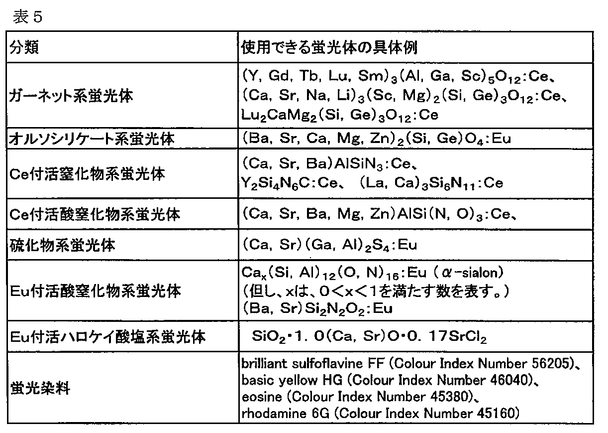
具体的には、蛍光体として以下に挙げるものを用いることが可能であるが、これらはあくまでも例示であり、本発明で使用できる蛍光体はこれらに限られるものではない。なお、以下の例示では、前述の通り、構造の一部のみが異なる蛍光体を、適宜省略して示している。 Specifically, the following phosphors can be used, but these are merely examples, and phosphors that can be used in the present invention are not limited to these. In the following examples, as described above, phosphors that differ only in part of the structure are omitted as appropriate.
<橙色ないし赤色蛍光体>
本発明に用いられる橙色ないし赤色蛍光体の発光ピーク波長は、通常570nm以上、好ましくは580nm以上、より好ましくは585nm以上、また、通常780nm以下、好ましくは700nm以下、より好ましくは680nm以下の波長範囲にあることが好適である。
このような橙色ないし赤色蛍光体として使用できる蛍光体を下表に示す。
<Orange to red phosphor>
The emission peak wavelength of the orange or red phosphor used in the present invention is usually 570 nm or more, preferably 580 nm or more, more preferably 585 nm or more, and usually 780 nm or less, preferably 700 nm or less, more preferably 680 nm or less. It is preferable that it exists in.
The phosphors that can be used as such orange or red phosphors are shown in the following table.
以上の中でも、赤色蛍光体としては、(Ca,Sr,Ba)2Si5(N,O)8:Eu、(Ca,Sr,Ba)Si(N,O)2:Eu、(Ca,Sr,Ba)AlSi(N,O)3:Eu、(Sr,Ba)3SiO5:Eu、(Ca,Sr)S:Eu、(La,Y)2O2S:Eu、Eu(ジベンゾイルメタン)3・1,10−フェナントロリン錯体
等のβ−ジケトン系Eu錯体、カルボン酸系Eu錯体、K2SiF6:Mnが好ましく、(Ca,Sr,Ba)2Si5(N,O)8:Eu、(Sr,Ca)AlSi(N,O):Eu、(La,Y)2O2S:Eu、K2SiF6:Mnがより好ましい。
また、橙色蛍光体としては、(Sr,Ba)3SiO5:Eu、(Sr,Ba)2SiO4:Eu、(Ca,Sr,Ba)2Si5(N,O)8:Eu、(Ca,Sr,Ba)AlSi(N,O)3:Ceが好ましい。
Among these, as the red phosphor, (Ca, Sr, Ba) 2 Si 5 (N, O) 8 : Eu, (Ca, Sr, Ba) Si (N, O) 2 : Eu, (Ca, Sr , Ba) AlSi (N, O) 3 : Eu, (Sr, Ba) 3 SiO 5 : Eu, (Ca, Sr) S: Eu, (La, Y) 2 O 2 S: Eu, Eu (dibenzoylmethane) ) 3 · 1,10-phenanthroline complexes of β- diketone Eu complex, a carboxylic acid Eu complex, K 2 SiF 6: Mn is preferred, (Ca, Sr, Ba) 2 Si 5 (N, O) 8: Eu, (Sr, Ca) AlSi (N, O): Eu, (La, Y) 2 O 2 S: Eu, K 2 SiF 6 : Mn are more preferable.
As the orange phosphor, (Sr, Ba) 3 SiO 5 : Eu, (Sr, Ba) 2 SiO 4 : Eu, (Ca, Sr, Ba) 2 Si 5 (N, O) 8 : Eu, ( Ca, Sr, Ba) AlSi (N, O) 3 : Ce is preferred.
<青色蛍光体>
青色蛍光体を使用する場合、当該青色蛍光体は本発明の効果を著しく損なわない限り任意のものを使用することができる。この際、青色蛍光体の発光ピーク波長は、通常420nm以上、好ましくは430nm以上、より好ましくは440nm以上、また、通常490nm以下、好ましくは480nm以下、より好ましくは470nm以下、更に好ましくは460nm以下の波長範囲にあることが好適である。
このような青色蛍光体として使用できる蛍光体を下表に示す。
<Blue phosphor>
When using blue fluorescent substance, the said blue fluorescent substance can use arbitrary things, unless the effect of this invention is impaired remarkably. At this time, the emission peak wavelength of the blue phosphor is usually 420 nm or more, preferably 430 nm or more, more preferably 440 nm or more, and usually 490 nm or less, preferably 480 nm or less, more preferably 470 nm or less, and further preferably 460 nm or less. It is preferable to be in the wavelength range.
The following table shows phosphors that can be used as such blue phosphors.
以上の中でも、青色蛍光体としては、(Ca,Sr,Ba)MgAl10O17:Eu、(Sr,Ca,Ba,Mg)10(PO4)6(Cl,F)2:Eu、(Ba,Ca,Mg,Sr)2SiO4:Eu、(Sr,Ca,Ba,Mg)10(PO4)6(Cl,F)2:Eu、(Ba,Ca,Sr)3MgSi2O8:Euが好ましく、(Ba,Sr)MgAl10O17:Eu、(Ca,Sr,Ba)10(PO4)6(Cl,F)2:Eu、Ba3MgSi2O8:Euがより好ましく、Sr10(PO4)6Cl2:Eu
、BaMgAl10O17:Euが特に好ましい。
Among these, as the blue phosphor, (Ca, Sr, Ba) MgAl 10 O 17 : Eu, (Sr, Ca, Ba, Mg) 10 (PO 4 ) 6 (Cl, F) 2 : Eu, (Ba , Ca, Mg, Sr) 2 SiO 4 : Eu, (Sr, Ca, Ba, Mg) 10 (PO 4 ) 6 (Cl, F) 2 : Eu, (Ba, Ca, Sr) 3 MgSi 2 O 8 : Eu is preferred, (Ba, Sr) MgAl 10 O 17 : Eu, (Ca, Sr, Ba) 10 (PO 4 ) 6 (Cl, F) 2 : Eu, Ba 3 MgSi 2 O 8 : Eu is more preferred, Sr 10 (PO 4 ) 6 Cl 2 : Eu
BaMgAl 10 O 17 : Eu is particularly preferable.
<緑色蛍光体>
緑色蛍光体を使用する場合、当該緑色蛍光体は本発明の効果を著しく損なわない限り任意のものを使用することができる。この際、緑色蛍光体の発光ピーク波長は、通常500nmより大きく、中でも510nm以上、更には515nm以上、また、通常550nm以下、中でも542nm以下、更には535nm以下の範囲であることが好ましい。この発光ピーク波長が短過ぎると青味を帯びる傾向がある一方で、長過ぎると黄味を帯びる傾向があり、何れも緑色光としての特性が低下する場合がある。
<Green phosphor>
When the green phosphor is used, any green phosphor can be used as long as the effect of the present invention is not significantly impaired. At this time, the emission peak wavelength of the green phosphor is usually larger than 500 nm, preferably 510 nm or more, more preferably 515 nm or more, and usually 550 nm or less, especially 542 nm or less, and further preferably 535 nm or less. If this emission peak wavelength is too short, it tends to be bluish, while if it is too long, it tends to be yellowish, and the characteristics as green light may deteriorate.
このような緑色蛍光体として利用できる蛍光体を下表に示す。 The phosphors that can be used as such green phosphors are shown in the table below.
以上の中でも、緑色蛍光体としては、Y3(Al,Ga)5O12:Ce、CaSc2O4:Ce、Ca3(Sc,Mg)2Si3O12:Ce、(Sr,Ba)2SiO4:Eu、(Si,Al)6(O,N)8:Eu(β−sialon)、(Ba,Sr)3Si6O12:N2:Eu、SrGa2S4:Eu、BaMgAl10O17:Eu,Mnが好ましい。 Among these, as the green phosphor, Y 3 (Al, Ga) 5 O 12 : Ce, CaSc 2 O 4 : Ce, Ca 3 (Sc, Mg) 2 Si 3 O 12 : Ce, (Sr, Ba) 2 SiO 4 : Eu, (Si, Al) 6 (O, N) 8 : Eu (β-sialon), (Ba, Sr) 3 Si 6 O 12 : N 2 : Eu, SrGa 2 S 4 : Eu, BaMgAl 10 O 17 : Eu, Mn is preferred.
得られる発光装置を照明装置に用いる場合には、Y3(Al,Ga)5O12:Ce、CaSc2O4:CeCa3(Sc,Mg)2Si3O12:Ce、(Sr,Ba)2SiO4:Eu、(Si,Al)6(O,N)8:Eu(β−sialon)、(Ba,Sr)3Si6O12:N2:Euが好ましい。
また、得られる発光装置を画像表示装置に用いる場合には、(Sr,Ba)2SiO4:Eu、(Si,Al)6(O,N)8:Eu(β−sialon)、(Ba,Sr)3Si6O12:N2:Eu、SrGa2S4:Eu、BaMgAl10O17:Eu,Mnが好ましい。
When the obtained light-emitting device is used for a lighting device, Y 3 (Al, Ga) 5 O 12 : Ce, CaSc 2 O 4 : CeCa 3 (Sc, Mg) 2 Si 3 O 12 : Ce, (Sr, Ba ) 2 SiO 4 : Eu, (Si, Al) 6 (O, N) 8 : Eu (β-sialon), (Ba, Sr) 3 Si 6 O 12 : N 2 : Eu are preferable.
When the obtained light emitting device is used for an image display device, (Sr, Ba) 2 SiO 4 : Eu, (Si, Al) 6 (O, N) 8 : Eu (β-sialon), (Ba, sr) 3 Si 6 O 12: N 2: Eu, SrGa 2 S 4: Eu, BaMgAl 10 O 17: Eu, Mn are preferable.
<黄色蛍光体>
黄色蛍光体を使用する場合、当該黄色蛍光体は本発明の効果を著しく損なわない限り任意のものを使用することができる。この際、黄色蛍光体の発光ピーク波長は、通常530nm以上、好ましくは540nm以上、より好ましくは550nm以上、また、通常620nm以下、好ましくは600nm以下、より好ましくは580nm以下の波長範囲にあることが好適である。
このような黄色蛍光体として利用できる蛍光体を下表に示す。
<Yellow phosphor>
When a yellow phosphor is used, any yellow phosphor can be used as long as the effects of the present invention are not significantly impaired. At this time, the emission peak wavelength of the yellow phosphor is usually in the wavelength range of 530 nm or more, preferably 540 nm or more, more preferably 550 nm or more, and usually 620 nm or less, preferably 600 nm or less, more preferably 580 nm or less. Is preferred.
The phosphors that can be used as such yellow phosphors are shown in the table below.
以上の中でも、黄色蛍光体としては、Y3Al5O12:Ce、(Y,Gd)3Al5O12:Ce、(Sr,Ca,Ba,Mg)2SiO4:Eu、(Ca,Sr)Si2N2O2:Eu及びα−サイアロン系蛍光体からなる群より選ばれる一種又は二種以上の黄色蛍光体が好ましい。
1つの蛍光体はそれ単独で、又は2つ以上のタイプの蛍光物質と任意の組成及び比率で用いることができる。
More in even, as the yellow phosphor, Y 3 Al 5 O 12: Ce, (Y, Gd) 3 Al 5 O 12: Ce, (Sr, Ca, Ba, Mg) 2 SiO 4: Eu, (Ca, One or two or more yellow phosphors selected from the group consisting of Sr) Si 2 N 2 O 2 : Eu and α-sialon phosphors are preferred.
One phosphor can be used alone or in any composition and ratio with two or more types of phosphors.
これらの蛍光体粒子の重量メジアン径は特に限定されないが、通常、100nm以上、
好ましくは2μm以上、より好ましくは5μm以上であり、そして通常、100μm以下、好ましくは50μm以下、より好ましくは20μm以下である。重量メジアン径が小さ過ぎると、輝度が低下し、蛍光体粒子が凝集してしまう傾向がある。一方、重量メジアン径が大き過ぎると、塗布ムラやディスペンサー等の閉塞が生じる傾向がある。
The weight median diameter of these phosphor particles is not particularly limited, but is usually 100 nm or more,
The thickness is preferably 2 μm or more, more preferably 5 μm or more, and usually 100 μm or less, preferably 50 μm or less, more preferably 20 μm or less. When the weight median diameter is too small, the luminance is lowered and the phosphor particles tend to aggregate. On the other hand, if the weight median diameter is too large, there is a tendency for coating unevenness and blockage of the dispenser to occur.
蛍光体粒子の形状は、半導体光放出装置部材に悪影響、例えば、蛍光物質部分の形成(formation)液体(本発明の半導体光放出装置部材の形成液体に蛍光体を添加することによ
り得られる液体)の流動性に悪影響を及ぼさない限り、特に制限されない。
本発明において、蛍光体の添加方法は特に限定されない。蛍光体が良好な分散状態にある場合、紫外線硬化性樹脂組成物中に蛍光体を後添加(post-mix)するだけで十分である。蛍光体に凝集傾向がある場合には、例えばシリコーン系紫外線硬化性樹脂組成物であればヒドロシリル化の前の原料に前もって混合することもできる。
さらに、蛍光体などの凝集や沈降を抑えるために、無機系の粒子を加えることも可能であり、無機系の粒子としては、例えば金属酸化物粒子、好ましくはヒュームドシリカなどを使用することができる。
The shape of the phosphor particles has an adverse effect on the semiconductor light emitting device member, for example, a phosphor formation liquid (a liquid obtained by adding a phosphor to the liquid forming the semiconductor light emitting device member of the present invention) As long as it does not adversely affect the fluidity of the liquid, there is no particular limitation.
In the present invention, the method for adding the phosphor is not particularly limited. If the phosphor is in a well dispersed state, it is sufficient to post-mix the phosphor into the UV curable resin composition. When the phosphor has a tendency to aggregate, for example, if it is a silicone-based ultraviolet curable resin composition, it can be mixed in advance with the raw material before hydrosilylation.
Furthermore, inorganic particles can be added to suppress aggregation and sedimentation of phosphors and the like, and as the inorganic particles, for example, metal oxide particles, preferably fumed silica can be used. it can.
また、硬化させるための紫外線を深部まで到達させるために紫外線吸収が比較的少ない粒子を蛍光体とともに封止樹脂組成物の中に入れておくことも非常に好ましい。このような粒子としては、例えばシリカ粒子やガラスビーズなどが挙げられる。中でも、天然石英粉や人工石英粉などは、紫外線の吸収が少ないという点と、屈折率が1.46と比較的高く、光取出し効率が稼げるという点から好ましい。この場合の粒子の粒径としては、通常5μm以上、好ましくは30μm以上、更に好ましくは60μm以上であり、通常500μm以下、好ましくは200μm以下、更に好ましくは100μm以下である。また、これら粒子の添加量としては、紫外線硬化性樹脂や蛍光体等を併せた紫外線硬化性樹脂組成物全体の重量に対して、通常0.1重量%以上、好ましくは1重量%以上、更に好ましく
は5重量%以上であり、通常70重量%以下、好ましくは50重量%以下、更に好ましくは30重量%以下、特に好ましくは15重量%以下である。前記粒子の添加量が少なすぎると、紫外線の到達度を高める効果が発現されない。前記粒子の添加量が多すぎると、使用時の半導体発光素子からの励起発光が素抜けることとなり好ましくない。
In addition, it is also very preferable to put particles with relatively little ultraviolet absorption in the sealing resin composition together with the phosphor in order to make the ultraviolet rays for curing reach the deep part. Examples of such particles include silica particles and glass beads. Of these, natural quartz powder and artificial quartz powder are preferable from the viewpoint that absorption of ultraviolet rays is small and the refractive index is relatively high at 1.46, so that light extraction efficiency can be increased. The particle size of the particles in this case is usually 5 μm or more, preferably 30 μm or more, more preferably 60 μm or more, and usually 500 μm or less, preferably 200 μm or less, more preferably 100 μm or less. The amount of these particles added is usually 0.1% by weight or more, preferably 1% by weight or more, based on the total weight of the UV curable resin composition including the UV curable resin and the phosphor. The amount is preferably 5% by weight or more, usually 70% by weight or less, preferably 50% by weight or less, more preferably 30% by weight or less, and particularly preferably 15% by weight or less. When the added amount of the particles is too small, the effect of increasing the reach of ultraviolet rays is not expressed. If the amount of the particles added is too large, the excited light emission from the semiconductor light emitting device during use is not preferable.
また、紫外線硬化性を担保する官能基としてアクリレート系の官能基を用いた場合には、そのごく一部が加水分解されると酸性の官能基となり、蛍光体が大気中の炭酸ガスや水分と反応して出来た表層の塩基性劣化物を捕捉し、封止層そのものの劣化を抑制する他、蛍光体の寿命の伸長にもつながるため好ましい。 In addition, when an acrylate-based functional group is used as a functional group that guarantees UV curability, an acidic functional group is obtained when only a small part of the functional group is hydrolyzed, and the phosphor is separated from carbon dioxide and moisture in the atmosphere. It is preferable because it captures the basic degradation product of the surface layer produced by the reaction, suppresses the degradation of the sealing layer itself, and also extends the lifetime of the phosphor.
[3−1−2]塗布工程
本発明において塗布工程とは、半導体発光素子上に前述の紫外線硬化性樹脂(前述の紫外線硬化性樹脂組成物を含む)を塗布する工程をいう。
本発明に用いられるのに好適な半導体発光素子としては、発光ピーク波長が350nm以上、500nm以下であるものが好ましい。これにより、紫外線硬化性樹脂を前記蛍光物質と組み合わせて、白色LED装置製造することができる。半導体発光素子のピーク波長として好ましい範囲としては、360nm以上430nm以下、または440nm以上480nm以下である。前者の場合は紫外から紫色光を発する半導体発光素子であり、後者の場合は青色光を発する半導体発光素子である。両者の中でも紫外から近紫外光を発する半導体発光素子は蛍光体との組合せにより様々な色温度を実現することができ、演色性の高い光源とすることができる点で好ましい。また、安全性の観点からは、ピーク波長が380nm以上430nm以下の近紫外光から紫色光を発する半導体発光素子やピーク波長が440nm以上480nm以下の青色光を発する半導体発光素子が好ましい。
[3-1-2] Application Step In the present invention, the application step refers to a step of applying the aforementioned ultraviolet curable resin (including the aforementioned ultraviolet curable resin composition) on the semiconductor light emitting device.
A semiconductor light emitting device suitable for use in the present invention preferably has an emission peak wavelength of 350 nm or more and 500 nm or less. Thereby, white LED device can be manufactured combining an ultraviolet curable resin with the said fluorescent substance. A preferable range for the peak wavelength of the semiconductor light emitting device is 360 nm to 430 nm, or 440 nm to 480 nm. The former is a semiconductor light emitting device that emits violet light from ultraviolet, and the latter is a semiconductor light emitting device that emits blue light. Among these, a semiconductor light emitting device emitting ultraviolet to near ultraviolet light is preferable in that various color temperatures can be realized by combining with a phosphor and a light source having high color rendering properties can be obtained. Further, from the viewpoint of safety, a semiconductor light emitting element that emits violet light from near ultraviolet light having a peak wavelength of 380 nm to 430 nm and a semiconductor light emitting element that emits blue light having a peak wavelength of 440 nm to 480 nm are preferable.
半導体発光素子のピーク波長が短すぎると、光のエネルギーが増大し、封止材や、その
他半導体発光装置の周辺材料の光劣化を助長する場合がある。また、半導体発光素子のピーク波長が長すぎると、蛍光体との組み合わせによって白色LED装置を実現することが困難である。
紫外線硬化性樹脂の塗布には、塗布対象物の種類や形状により、ポッティング・スピンコート・印刷などの各種塗布方法を選択することができる。
If the peak wavelength of the semiconductor light emitting element is too short, the energy of light increases, which may promote photodegradation of the sealing material and other peripheral materials of the semiconductor light emitting device. Moreover, if the peak wavelength of the semiconductor light emitting device is too long, it is difficult to realize a white LED device by combining with a phosphor.
For the application of the ultraviolet curable resin, various coating methods such as potting, spin coating, and printing can be selected depending on the type and shape of the object to be coated.
また、封止材として本発明の紫外線硬化性樹脂を使用する場合、封止層の構造として、二層構造とし、(i)下層を紫外線照射によって硬化させ、上層を熱硬化によって硬化させるシステムや、逆に(ii)下層を熱硬化によって硬化させ、上層を紫外線照射によって硬化させるシステムも好適である。
(i)下層を紫外線照射によって硬化させ、上層を熱硬化によって硬化させるシステムとしては、例えば、下層に蛍光体を含まない紫外線硬化性樹脂を使用し、紫外線照射で素早く経済的に硬化させた後、上層に熱硬化性の蛍光体ペースト(蛍光体を含有する熱硬化性樹脂)を使用するシステムが挙げられる。これにより、蛍光体を半導体発光素子から遠ざけて、半導体発光素子による蛍光体の劣化を防止することができる。
Further, when the ultraviolet curable resin of the present invention is used as a sealing material, the structure of the sealing layer is a two-layer structure, (i) a system in which the lower layer is cured by ultraviolet irradiation and the upper layer is cured by thermosetting, Conversely, (ii) a system in which the lower layer is cured by thermal curing and the upper layer is cured by ultraviolet irradiation is also suitable.
(I) As a system for curing the lower layer by ultraviolet irradiation and curing the upper layer by heat curing, for example, after using an ultraviolet curable resin not containing a phosphor in the lower layer and quickly and economically curing by ultraviolet irradiation And a system using a thermosetting phosphor paste (thermosetting resin containing a phosphor) as an upper layer. Accordingly, the phosphor can be kept away from the semiconductor light emitting element, and deterioration of the phosphor due to the semiconductor light emitting element can be prevented.
(ii)下層を熱硬化によって硬化させ、上層を紫外線照射によって硬化させるシステムとしては、例えば、熱硬化性の蛍光体ペーストを硬化させた後、上層に蛍光体を含まない紫外線硬化性樹脂を塗布、硬化させるシステムが挙げられる。これにより、上層は、半導体発光装置のレンズや、ガスバリアのための蓋の役割を担保させることができ、また特に上層については素早く経済的に硬化させることが出来る。 (Ii) As a system for curing the lower layer by thermal curing and curing the upper layer by ultraviolet irradiation, for example, after curing a thermosetting phosphor paste, an ultraviolet curable resin not containing a phosphor is applied to the upper layer. And a curing system. Thereby, the upper layer can secure the role of the lens for the semiconductor light emitting device and the lid for the gas barrier, and the upper layer can be cured quickly and economically.
この場合の下層と上層の平均厚みの比としては、いずれも通常1/10以上、好ましくは3/7であり、通常10/1以下、好ましくは7/3である。
また、上記(i)、(ii)のシステムを組み合わせることができる。例えば、上層、下層のいずれも紫外線硬化性樹脂を用いて、迅速な硬化処理を期待することができる。さらに、例えば三層以上の多層構造をとるシステムを適宜設計することもできる。
In this case, the ratio between the average thicknesses of the lower layer and the upper layer is usually 1/10 or more, preferably 3/7, and usually 10/1 or less, preferably 7/3.
Further, the above systems (i) and (ii) can be combined. For example, a rapid curing process can be expected by using an ultraviolet curable resin for both the upper layer and the lower layer. Furthermore, for example, a system having a multilayer structure of three or more layers can be appropriately designed.
[3−2]パッケージ材料としての実施態様
第二の本発明の半導体発光装置の製造方法は、半導体発光素子を搭載するパッケージを製造する工程を有するが、この工程で、前述の(A)工程を有し、好ましくは(B)工程を有する。
以下、パッケージを製造する工程について詳述する。なお、本発明において、パッケージを製造する工程がこの実施態様のみに限定されないことはいうまでもない。
[3-2] Embodiment as Package Material The method for manufacturing a semiconductor light emitting device according to the second aspect of the present invention includes a step of manufacturing a package on which a semiconductor light emitting element is mounted. Preferably, it has (B) process.
Hereinafter, the process of manufacturing the package will be described in detail. In the present invention, it goes without saying that the process of manufacturing the package is not limited to this embodiment.
半導体発光素子を搭載するパッケージを製造する工程としては、主に紫外線硬化性樹脂を調製する工程、紫外線硬化性樹脂をパッケージの型に入れる工程、前記(A)工程、前記(B)工程、硬化物を型から取り出す工程を有する。以下、紫外線硬化性樹脂を調製する工程(以下、「調製工程」と称することがある。)、紫外線硬化性樹脂をパッケージの型に入れる工程(以下、「型入れ工程」と称することがある。)硬化物を型から取り出す工程(取り出し工程)について詳述する。 As a process of manufacturing a package mounting a semiconductor light emitting element, a process of mainly preparing an ultraviolet curable resin, a process of putting an ultraviolet curable resin into a mold of the package, the process (A), the process (B), and curing A step of removing the object from the mold. Hereinafter, a step of preparing an ultraviolet curable resin (hereinafter sometimes referred to as “preparation step”) and a step of placing the ultraviolet curable resin in a package mold (hereinafter referred to as “molding step”). ) The step of taking out the cured product from the mold (takeout step) will be described in detail.
[3−2−1]調製工程
本発明において調製工程とは、前述の紫外線硬化性樹脂を製造し、適宜、所定の添加物を混合することにより紫外線硬化性樹脂組成物とする工程をいう。
特に、第二の本発明の製造方法において紫外線硬化性樹脂は、例えば、白色無機酸化物粒子を分散させることによりパッケージ材料として使用することができる。白色の無機酸化物粒子は、パッケージ内部の反射率を高めて半導体発光装置の光取り出しを実現するのに有効である。
[3-2-1] Preparation Step In the present invention, the preparation step refers to a step of producing the above-described ultraviolet curable resin and appropriately mixing predetermined additives to obtain an ultraviolet curable resin composition.
In particular, in the production method of the second aspect of the present invention, the ultraviolet curable resin can be used as a packaging material, for example, by dispersing white inorganic oxide particles. The white inorganic oxide particles are effective for increasing the reflectance inside the package and realizing light extraction of the semiconductor light emitting device.
前述の通り、本発明の製造方法においては、(A)工程における硬化によって、パッケージの形状や無機酸化物粒子の紫外線吸収に起因する硬化ムラを低減することができるため、このような観点からも技術的意義を大いに有する。 As described above, in the manufacturing method of the present invention, the curing in the step (A) can reduce unevenness in curing due to the shape of the package and the ultraviolet absorption of the inorganic oxide particles. It has great technical significance.
[3−2−2]型入れ工程
本発明において型入れ工程とは、前述の紫外線硬化性樹脂(前述の紫外線硬化性樹脂組成物を含む)をパッケージの型に入れる工程をいう。ここで、紫外線硬化性樹脂を入れる前に、半導体発光素子を搭載した金属リードフレームまたは半導体発光素子を搭載しない金属リードフレームを準備し、これを型内に予め設置しておくこともできる。また、型は、紫外線を透過する石英等の材料を用いることができる。
[3-2-2] Mold Placement Step In the present invention, the mold placement step refers to a step of placing the aforementioned ultraviolet curable resin (including the aforementioned ultraviolet curable resin composition) into a package mold. Here, before putting the ultraviolet curable resin, a metal lead frame on which a semiconductor light emitting element is mounted or a metal lead frame on which a semiconductor light emitting element is not mounted can be prepared and previously set in a mold. For the mold, a material such as quartz that transmits ultraviolet rays can be used.
[3−2−3]取り出し工程
本発明において取り出し工程とは、(A)工程で硬化した硬化物を型から取り出す工程をいう。取り出し工程は通常(A)工程の後に行うが、(B)工程がある場合は(B)工程の前または後に実施される。取り出し時の破損を抑制する観点からは、取り出し工程は(B)工程の後に実施されるのが好ましい。
[3-2-3] Extraction step In the present invention, the extraction step refers to a step of removing the cured product cured in step (A) from the mold. The extraction step is usually performed after the step (A), but when there is a step (B), it is carried out before or after the step (B). From the viewpoint of suppressing breakage during removal, the removal step is preferably performed after step (B).
本発明を実施例によりさらに詳細に説明するが、本発明の要旨を逸脱しない限り、本発明は下記の実施例に制約されるものではない。
[1]耐紫外線照射試験および耐熱性試験
本発明の半導体発光装置への適用性について、紫外線硬化性組成物の硬化物の基本物性の観点から検討することを目的として、下記の耐紫外線照射試験および耐熱性試験を実施した。
The present invention will be described in more detail with reference to examples. However, the present invention is not limited to the following examples without departing from the gist of the present invention.
[1] Ultraviolet irradiation resistance test and heat resistance test The following ultraviolet radiation resistance test is conducted for the purpose of examining the applicability to the semiconductor light emitting device of the present invention from the viewpoint of the basic physical properties of the cured product of the ultraviolet curable composition. And a heat resistance test was carried out.
[実施例1]
回転子を備えた小瓶中で、信越化学社製の側鎖型アクリルフェニル含有シリコーン(X−22−2477)3gにDKSHジャパン社製の光ラジカル開始剤Luna200を0.015g混合溶解させて実施例1の紫外線硬化性樹脂組成物を得た。この紫外線硬化性樹脂組成物を直径5cmのテフロン(登録商標)シャーレに厚さ2mmとなるように入れ、窒素雰囲気下にてアイグラフィックス社製ECS−151U(1500W高圧水銀ランプ)を用いて300mJ/cm2のエネルギーの紫外線(照射時間20秒)を60℃下にて照射して硬化させた。硬化樹脂中における珪素と珪素に隣接する酸素の割合は合わせて約46重量%であると算出された。
硬化後の膜(「自立膜」と称する。以下同じ)について、以下の耐紫外線照射試験、および耐熱性試験を行った。
[Example 1]
Example: In a small bottle equipped with a rotor, 0.015 g of photoradical initiator Luna200 made by DKSH Japan was mixed and dissolved in 3 g of side chain type acrylic phenyl-containing silicone (X-22-2477) made by Shin-Etsu Chemical Co., Ltd. 1 UV curable resin composition was obtained. This ultraviolet curable resin composition was placed in a Teflon (registered trademark) petri dish having a diameter of 5 cm so as to have a thickness of 2 mm, and 300 mJ using an ECS-151U (1500 W high-pressure mercury lamp) manufactured by Eye Graphics Co., Ltd. in a nitrogen atmosphere. Curing was performed by irradiation with ultraviolet rays (irradiation time: 20 seconds) at an energy of / cm 2 at 60 ° C. The total proportion of silicon and oxygen adjacent to silicon in the cured resin was calculated to be about 46% by weight.
The cured film (referred to as “self-supporting film”, hereinafter the same) was subjected to the following ultraviolet irradiation test and heat resistance test.
<耐紫外線照射試験>
大気中室温にて松下電工マシンアンドビジョン社製紫外線硬化装置アイキュアANUP5204からの光(2100mW/cm2)を朝日分光社製の光学フィルターを用いて350nm以下の光をカットして照射したところ、20時間照射させた後の膜のYI値は2.34であった。YI値は日本電色工業株式会社製のCOH−300Aを用いて測定した。
<Ultraviolet irradiation test>
When light (2100 mW / cm 2 ) from an ultraviolet curing device Aicure ANUP5204 manufactured by Matsushita Electric Works and Vision Co., Ltd. was cut at a room temperature in the atmosphere using an optical filter manufactured by Asahi Spectroscopic Co., Ltd., 20 nm was irradiated. The YI value of the film after time irradiation was 2.34. The YI value was measured using COH-300A manufactured by Nippon Denshoku Industries Co., Ltd.
<耐熱性試験>
また、150℃大気下にて500時間保持した後の自立膜のYI値を測定したところ、1.93であった。さらに、200℃大気下にて500時間保持した後の自立膜のYI値を測定したところ、74.09であった。
<Heat resistance test>
Further, the YI value of the self-supporting film after being held in the atmosphere at 150 ° C. for 500 hours was 1.93. Furthermore, when the YI value of the free-standing film after being held at 200 ° C. for 500 hours was measured, it was 74.09.
[実施例2]
実施例1の側鎖型アクリルフェニル含有シリコーン(X−22−2477)の代わりに信越化学社製両末端型メタクリル変性ジメチルシリコーン(X−22−164)を3g使用した以外は実施例1と同様にして液を調製し、実施例2の紫外線硬化性樹脂組成物を得た。この紫外線硬化性樹脂組成物を直径5cmのテフロン(登録商標)シャーレに厚さ2mmとなるように入れ、窒素雰囲気下60℃にて300mJ/cm2のエネルギーの紫外線照射(照射時間20秒)を行なって硬化させた。硬化樹脂中における珪素と珪素に隣接する酸素の割合は合わせて約18重量%であると算出された。
硬化後の自立膜について、実施例1と同様に耐熱性試験を実施した。その結果、150℃および200℃におけるYI値は、それぞれ3.81および140.99であった。
[Example 2]
The same as Example 1 except that 3 g of both-end type methacryl-modified dimethyl silicone (X-22-164) manufactured by Shin-Etsu Chemical Co., Ltd. was used instead of the side chain type acrylic phenyl-containing silicone (X-22-2477) of Example 1. Thus, a liquid was prepared to obtain an ultraviolet curable resin composition of Example 2. This ultraviolet curable resin composition was placed in a Teflon (registered trademark) petri dish having a diameter of 5 cm so as to have a thickness of 2 mm, and irradiated with ultraviolet rays (irradiation time: 20 seconds) with an energy of 300 mJ / cm 2 at 60 ° C. in a nitrogen atmosphere. And then cured. The total proportion of silicon and oxygen adjacent to silicon in the cured resin was calculated to be about 18% by weight.
About the self-supporting film after curing, the heat resistance test was performed in the same manner as in Example 1. As a result, the YI values at 150 ° C. and 200 ° C. were 3.81 and 140.99, respectively.
[実施例3]
実施例1の側鎖型アクリルフェニル含有シリコーン(X−22−2477)の代わりに信越化学社製両末端型メタクリル変性ジメチルシリコーン(X−22−164A)を3.5g使用し、光ラジカル開始剤としてLuna200の代わりにESACURE KTO46を0.0175g使用した以外は実施例1と同様にして液を調製し、実施例3の紫外線硬化性樹脂組成物を得た。この紫外線硬化性樹脂組成物を直径5cmのテフロン(登録商標)シャーレに厚さ2mmとなるように入れ、窒素雰囲気下60℃にて300mJ/cm2のエネルギーの紫外線照射(照射時間20秒)を行なって硬化させた。硬化樹脂中における珪素と珪素に隣接する酸素の割合は合わせて約50重量%であると算出された。
[Example 3]
Instead of the side chain type acrylic phenyl-containing silicone (X-22-2477) of Example 1, 3.5 g of both-end type methacryl-modified dimethyl silicone (X-22-164A) manufactured by Shin-Etsu Chemical Co., Ltd. was used, and a photo radical initiator was used. A liquid was prepared in the same manner as in Example 1 except that 0.0175 g of ESACURE KTO46 was used instead of Luna200, and an ultraviolet curable resin composition of Example 3 was obtained. This ultraviolet curable resin composition was placed in a Teflon (registered trademark) petri dish having a diameter of 5 cm so as to have a thickness of 2 mm, and irradiated with ultraviolet rays (irradiation time: 20 seconds) with an energy of 300 mJ / cm 2 at 60 ° C. in a nitrogen atmosphere. And then cured. The total proportion of silicon and oxygen adjacent to silicon in the cured resin was calculated to be about 50% by weight.
硬化後の自立膜について、実施例1と同様に紫外線照射試験を実施した。その結果、YI値は1.93であった。
また、実施例1と同様の耐熱性試験を実施した。その結果、150℃および200℃におけるYI値は、それぞれ1.46および48.47であった。
For the self-supporting film after curing, an ultraviolet irradiation test was performed in the same manner as in Example 1. As a result, the YI value was 1.93.
Moreover, the heat resistance test similar to Example 1 was implemented. As a result, the YI values at 150 ° C. and 200 ° C. were 1.46 and 48.47, respectively.
[実施例4]
実施例3の信越化学社製両末端型メタクリル変性ジメチルシリコーン(X−22−164A)の代わりに信越化学社製両末端型メタクリル変性ジメチルシリコーン(X−22−164C)を3.5g使用した以外は実施例3と同様にして液を調製し実施例4の紫外線硬化性樹脂組成物を得た。この紫外線硬化性樹脂組成物を直径5cmのテフロン(登録商標)シャーレに厚さ2mmとなるように入れ、窒素雰囲気下60℃にて300mJ/cm2のエネルギーの紫外線照射(照射時間20秒)を行なって硬化させた。硬化樹脂中における珪素と珪素に隣接する酸素の割合は合わせて約56重量%であると算出された。
[Example 4]
Instead of using 3.5 g of both-end type methacryl-modified dimethyl silicone (X-22-164C) manufactured by Shin-Etsu Chemical Co., Ltd. instead of the both-end type methacryl-modified dimethyl silicone (X-22-164A) manufactured by Shin-Etsu Chemical Co., Ltd. in Example 3. Prepared a liquid in the same manner as in Example 3 to obtain an ultraviolet curable resin composition of Example 4. This ultraviolet curable resin composition was placed in a Teflon (registered trademark) petri dish having a diameter of 5 cm so as to have a thickness of 2 mm, and irradiated with ultraviolet rays (irradiation time: 20 seconds) with an energy of 300 mJ / cm 2 at 60 ° C. in a nitrogen atmosphere. And then cured. The total proportion of silicon and oxygen adjacent to silicon in the cured resin was calculated to be about 56% by weight.
硬化後の自立膜について、実施例1と同様に紫外線照射試験を実施した。その結果、YI値は2.01であった。
また、実施例1と同様の耐熱性試験を実施した。その結果、150℃および200℃におけるYI値は、それぞれ1.71および10.26であった。
For the self-supporting film after curing, an ultraviolet irradiation test was performed in the same manner as in Example 1. As a result, the YI value was 2.01.
Moreover, the heat resistance test similar to Example 1 was implemented. As a result, the YI values at 150 ° C. and 200 ° C. were 1.71 and 10.26, respectively.
[実施例5]
実施例3の信越化学社製両末端型メタクリル変性ジメチルシリコーン(X−22−164A)の代わりに信越化学社製両末端型メタクリル変性ジメチルシリコーン(X−22−164B)を3.5g使用した以外は実施例3と同様にして液を調製し実施例5の紫外線硬化性樹脂組成物を得た。この紫外線硬化性樹脂組成物を直径5cmのテフロン(登録商標)シャーレに厚さ2mmとなるように入れ、窒素雰囲気下60℃にて300mJ/cm2のエネルギーの紫外線照射(照射時間20秒)を行なって硬化させた。硬化樹脂中における珪素と珪素に隣接する酸素の割合は合わせて約54重量%であると算出された。
[Example 5]
Except for using 3.5 g of both-end type methacryl-modified dimethyl silicone (X-22-164B) manufactured by Shin-Etsu Chemical Co., Ltd. instead of the both-end type methacryl-modified dimethyl silicone (X-22-164A) manufactured by Shin-Etsu Chemical Co., Ltd. in Example 3. Prepared a liquid in the same manner as in Example 3 to obtain an ultraviolet curable resin composition of Example 5. This ultraviolet curable resin composition was placed in a Teflon (registered trademark) petri dish having a diameter of 5 cm so as to have a thickness of 2 mm, and irradiated with ultraviolet rays (irradiation time: 20 seconds) with an energy of 300 mJ / cm 2 at 60 ° C. in a nitrogen atmosphere. And then cured. The total proportion of silicon and oxygen adjacent to silicon in the cured resin was calculated to be about 54% by weight.
硬化後の自立膜について、実施例1と同様に紫外線照射試験を実施した。その結果、YI値は2.43であった。
また、実施例1と同様の耐熱性試験を実施した。その結果、150℃および200℃におけるYI値は、それぞれ2.29および17.56であった。
For the self-supporting film after curing, an ultraviolet irradiation test was performed in the same manner as in Example 1. As a result, the YI value was 2.43.
Moreover, the heat resistance test similar to Example 1 was implemented. As a result, the YI values at 150 ° C. and 200 ° C. were 2.29 and 17.56, respectively.
[実施例6]
実施例1の信越化学社製側鎖型アクリルフェニル含有シリコーン(X−22−2477)の代わりに信越化学社製両末端型メタクリル変性ジメチルシリコーン(X−22−164E)を3g使用した以外は実施例1と同様にして液を調製し実施例6の紫外線硬化性樹脂組成物を得た。この紫外線硬化性樹脂組成物を直径5cmのテフロン(登録商標)シャーレに厚さ2mmとなるように入れ、窒素雰囲気下60℃にて300mJ/cm2のエネルギーの紫外線照射(照射時間20秒)を行なって硬化させた。硬化樹脂中における珪素と珪素に隣接する酸素の割合は合わせて約57重量%であると算出された。
硬化後の自立膜について、実施例1と同様に耐熱性試験を実施した。その結果、150℃および200℃におけるYI値は、それぞれ1.51および3.67であった。
[Example 6]
Implemented except that 3 g of both-end type methacryl-modified dimethyl silicone (X-22-164E) manufactured by Shin-Etsu Chemical Co., Ltd. was used instead of the side chain type acrylic phenyl-containing silicone (X-22-2477) manufactured by Shin-Etsu Chemical Co., Ltd. of Example 1. A liquid was prepared in the same manner as in Example 1 to obtain an ultraviolet curable resin composition of Example 6. This ultraviolet curable resin composition was placed in a Teflon (registered trademark) petri dish having a diameter of 5 cm so as to have a thickness of 2 mm, and irradiated with ultraviolet rays (irradiation time: 20 seconds) with an energy of 300 mJ / cm 2 at 60 ° C. in a nitrogen atmosphere. And then cured. The total proportion of silicon and oxygen adjacent to silicon in the cured resin was calculated to be about 57% by weight.
About the self-supporting film after curing, the heat resistance test was performed in the same manner as in Example 1. As a result, the YI values at 150 ° C. and 200 ° C. were 1.51 and 3.67, respectively.
[実施例7]
実施例1の信越化学社製側鎖型アクリルフェニル含有シリコーン(X−22−2477)の代わりにジレスト社製側鎖型メタクリロキシプロピル変性ジメチルシリコーン(UMS−182)を2.5g使用し、Luna200を0.0125g使用した以外は実施例1と同様にして液を調製し実施例7の紫外線硬化性樹脂組成物を得た。この紫外線硬化性樹脂組成物を直径5cmのテフロン(登録商標)シャーレに厚さ2mmとなるように入れ、窒素雰囲気下60℃にて300mJ/cm2のエネルギーの紫外線照射(照射時間20秒)を行なって硬化させた。硬化樹脂中における珪素と珪素に隣接する酸素の割合は合わせて約45重量%であると算出された。
[Example 7]
In place of the side chain type acrylic phenyl-containing silicone (X-22-2477) manufactured by Shin-Etsu Chemical Co., Ltd. in Example 1, 2.5 g of side chain type methacryloxypropyl modified dimethyl silicone (UMS-182) manufactured by Gilest Co., Ltd. was used. A liquid was prepared in the same manner as in Example 1 except that 0.0125 g was used, and an ultraviolet curable resin composition of Example 7 was obtained. This ultraviolet curable resin composition was placed in a Teflon (registered trademark) petri dish having a diameter of 5 cm so as to have a thickness of 2 mm, and irradiated with ultraviolet rays (irradiation time: 20 seconds) with an energy of 300 mJ / cm 2 at 60 ° C. in a nitrogen atmosphere. And then cured. The total proportion of silicon and oxygen adjacent to silicon in the cured resin was calculated to be about 45% by weight.
硬化後の自立膜について、実施例1と同様に耐熱性試験を実施した。その結果、150℃および200℃におけるYI値は、それぞれ3.85および108.54であった。 About the self-supporting film after curing, the heat resistance test was performed in the same manner as in Example 1. As a result, the YI values at 150 ° C. and 200 ° C. were 3.85 and 108.54, respectively.
[実施例8]
実施例7の基質としてジレスト社製側鎖型メタクリロキシプロピル変性ジメチルシリコーン(UMS−182)2.5gの他に、アルドリッチ社製Poly(propylene glycol) dimethacrylateを0.5g使用し、Luna200を0.015g使用した以外は実施例7
と同様にして液を調製し実施例8の紫外線硬化性樹脂組成物を得た。この紫外線硬化性樹脂組成物を直径5cmのテフロン(登録商標)シャーレに厚さ2mmとなるように入れ、窒素雰囲気下60℃にて300mJ/cm2のエネルギーの紫外線照射(照射時間20秒)を行なって硬化させた。硬化樹脂中における珪素と珪素に隣接する酸素の割合は合わせて約37重量%であると算出された。
[Example 8]
In addition to 2.5 g of side chain methacryloxypropyl-modified dimethylsilicone (UMS-182) manufactured by Dilest as a substrate of Example 7, 0.5 g of Poly (propylene glycol) dimethacrylate manufactured by Aldrich was used, and Luna200 was added in an amount of 0. Example 7 except that 015 g was used
A liquid was prepared in the same manner as described above to obtain an ultraviolet curable resin composition of Example 8. This ultraviolet curable resin composition was placed in a Teflon (registered trademark) petri dish having a diameter of 5 cm so as to have a thickness of 2 mm, and irradiated with ultraviolet rays (irradiation time: 20 seconds) with an energy of 300 mJ / cm 2 at 60 ° C. in a nitrogen atmosphere. And then cured. The total proportion of silicon and oxygen adjacent to silicon in the cured resin was calculated to be about 37% by weight.
硬化後の自立膜について、実施例1と同様に耐熱性試験を実施した。その結果、150℃および200℃におけるYI値は、それぞれ9.93および155.79であった。 About the self-supporting film after curing, the heat resistance test was performed in the same manner as in Example 1. As a result, the YI values at 150 ° C. and 200 ° C. were 9.93 and 155.79, respectively.
[実施例9]
真空蒸留によって低分子環状シロキサン群をはじめとする低沸点成分をカットしたジレスト社製両末端ビニル基変性ジメチルシリコーン(DMS−V22)3gと信越化学社製側鎖型メルカプト変性ジメチルシリコーン(KF−2001)1.28g、DKSHジャパン社製の光ラジカル開始剤Luna200をを0.0021g混合溶解させて実施例9の紫外線硬化性樹脂組成物を得た。この紫外線硬化性樹脂組成物を直径5cmのテフロン(登録商標)シャーレに厚さ2mmとなるように入れ、窒素雰囲気下60℃にて300mJ/cm2のエネルギーの紫外線照射(照射時間20秒)を行なって硬化させた。硬化樹脂中における珪素と珪素に隣接する酸素の割合は合わせて約58重量%であると算出された。
[Example 9]
Low-boiling components such as low molecular weight cyclic siloxane groups were cut by vacuum distillation, and 3 g of both-end vinyl group-modified dimethyl silicone (DMS-V22) manufactured by Gilest and side chain mercapto-modified dimethyl silicone (KF-2001) manufactured by Shin-Etsu Chemical Co., Ltd. ) 1.28 g, 0.0021 g of a photoradical initiator Luna200 manufactured by DKSH Japan was mixed and dissolved to obtain an ultraviolet curable resin composition of Example 9. This ultraviolet curable resin composition was placed in a Teflon (registered trademark) petri dish having a diameter of 5 cm so as to have a thickness of 2 mm, and irradiated with ultraviolet rays (irradiation time: 20 seconds) with an energy of 300 mJ / cm 2 at 60 ° C. in a nitrogen atmosphere. And then cured. The total proportion of silicon and oxygen adjacent to silicon in the cured resin was calculated to be about 58% by weight.
硬化後の自立膜について、実施例1と同様に耐紫外線照射試験を実施した。ただし、紫外線照射時間は5時間とした。その結果、YI値は、45.37であった。 For the self-supporting film after curing, an ultraviolet irradiation resistance test was conducted in the same manner as in Example 1. However, the ultraviolet irradiation time was 5 hours. As a result, the YI value was 45.37.
[実施例10]
モメンティブ・パフォーマンス・マテリアルズ・ジャパン合同会社製両末端シラノールジメチルシリコーンオイルYF−3800を15g、信越化学社製メタクリロキシプロピルトリメトキシシランを1.66g、触媒として和光純薬社製オクタン酸錫を0.0133gを、回転子、ジムロートコンデンサを設置した100mLナスフラスコ中ににて室温にて15分および80℃にて30分攪拌した。この後、反応液を100℃まで昇温して触媒を完全溶解し、100℃全還流下で30分間500rpmで攪拌しつつ初期加水分解を行った。その後、ロータリーエバポレーターを用いて室温、1kPaで10分間微残留しているメタノール及び水分、低沸ケイ素成分を留去した。得られた液10.8gにDKSHジャパン社製の光ラジカル開始剤Luna100を0.54g混合溶解させて実施例10の紫外線硬化性樹脂組成物を得た。この紫外線硬化性樹脂組成物を直径5cmのテフロン(登録商標)シャーレに厚さ2mmとなるように入れ、窒素雰囲気下60℃にて300mJ/cm2のエネルギーの紫外線照射(照射時間20秒)を行なって硬化させた。硬化樹脂中における珪素と珪素に隣接する酸素の割合は合わせて約55重量%であると算出された。
[Example 10]
Momentive Performance Materials Japan Godo Kaisha Terminal Silanol Dimethyl Silicone Oil YF-3800 15g, Shinetsu Chemical Co., Ltd. Methacryloxypropyltrimethoxysilane 1.66g, Wako Pure Chemical Industries,
[比較例1]
実施例7のジレスト社製側鎖型メタクリロキシプロピル変性ジメチルシリコーン(UMS−182)を6gスケールに変更して光ラジカル開始剤Luna200を0.03g使用した以外は実施例6と同様にして液を調製し比較例1の紫外線硬化性樹脂組成物を得た。この紫外線硬化性樹脂組成物を、窒素雰囲気下にてアイグラフィックス社製ECS−151U(1500W高圧水銀ランプ)を用いて300mJ/cm2のエネルギーの紫外線(照射時間20秒)を15℃および30℃下にて照射して硬化させた。硬化物の硬度を表6に示した。その結果、300mJ/cm2程度のエネルギーで素早く高い架橋度で硬化させるためには、紫外線照射と同時に加熱をすることが好ましいことが判明した。
[Comparative Example 1]
A liquid was prepared in the same manner as in Example 6 except that the side chain type methacryloxypropyl-modified dimethyl silicone (UMS-182) manufactured by Gilest in Example 7 was changed to 6 g scale and 0.03 g of the photoradical initiator Luna200 was used. The UV curable resin composition of Comparative Example 1 was prepared. This ultraviolet curable resin composition was subjected to ultraviolet rays (
[比較例2]
信越化学社製フォトデバイス用熱硬化性透明封止樹脂SCR−1011のA液とB液を100重量部ずつ混合し、この液を直径5cmのテフロン(登録商標)シャーレに厚さ2m
mとなるように入れて70℃にて1時間および150℃にて5時間加熱することで硬化させた。
[Comparative Example 2]
100 parts by weight of A and B liquids of thermosetting transparent sealing resin SCR-1011 for photo devices manufactured by Shin-Etsu Chemical Co., Ltd. were mixed, and this liquid was 2 m thick in a Teflon (registered trademark) petri dish with a diameter of 5 cm.
m, and cured by heating at 70 ° C. for 1 hour and 150 ° C. for 5 hours.
硬化後の自立膜について、実施例1と同様に紫外線照射試験を実施した。その結果、YI値は74.25であった。
また、実施例1と同様の耐熱性試験を実施した。その結果、150℃におけるYI値は、45.37であった。この結果から、従来の熱硬化性の信越化学社製フォトデバイス用透明封止樹脂SCR−1011を用いたLEDの製造方法と比較して、本発明の製造方法は硬化時間が極めて早く、着色の観点における耐久性にも極めて優れた効果を奏すること
が判明した。
For the self-supporting film after curing, an ultraviolet irradiation test was performed in the same manner as in Example 1. As a result, the YI value was 74.25.
Moreover, the heat resistance test similar to Example 1 was implemented. As a result, the YI value at 150 ° C. was 45.37. From this result, compared with the manufacturing method of LED using the conventional thermosetting Shin-Etsu Chemical Co., Ltd. transparent sealing resin SCR-1011 for photo devices, the manufacturing method of the present invention has a very fast curing time, It was found that the durability in terms of durability was extremely excellent.
[比較例3]
実施例1の信越化学社製の側鎖型アクリルフェニル含有シリコーン(X−22−2477)を日本化薬社製のウレタンアクリレートUXF―3204Aに変更した以外は実施例1と同様にして液を調製し比較例3の紫外線硬化性樹脂組成物を得た。この紫外線硬化性樹脂組成物を直径5cmのテフロン(登録商標)シャーレに厚さ2mmとなるように入れ、窒素雰囲気下60℃にて300mJ/cm2のエネルギーの紫外線照射(照射時間20秒)を行なって硬化させた。硬化樹脂中における珪素と珪素に隣接する酸素の割合は合わせて約0重量%であると算出された。
[Comparative Example 3]
A liquid was prepared in the same manner as in Example 1 except that the side chain type acrylic phenyl-containing silicone (X-22-2477) manufactured by Shin-Etsu Chemical Co., Ltd. in Example 1 was changed to urethane acrylate UXF-3204A manufactured by Nippon Kayaku Co., Ltd. Then, an ultraviolet curable resin composition of Comparative Example 3 was obtained. This ultraviolet curable resin composition was placed in a Teflon (registered trademark) petri dish having a diameter of 5 cm so as to have a thickness of 2 mm, and irradiated with ultraviolet rays (irradiation time: 20 seconds) with an energy of 300 mJ / cm 2 at 60 ° C. in a nitrogen atmosphere. And then cured. The total proportion of silicon and oxygen adjacent to silicon in the cured resin was calculated to be about 0% by weight.
硬化後の自立膜について、実施例1と同様に耐紫外線照射試験を実施したが、数分後に自立膜激しく茶変したために照射を中断した。また、実施例1と同様の耐熱性試験を実施した。その結果、150℃および200℃におけるYI値は、それぞれ40.20であった。
この結果から、珪素と珪素に隣接する酸素の含有量の低い紫外線硬化性樹脂を用いたLEDの製造方法と比較して、本発明の製造方法は、着色の問題がなく、耐久性が極めて優れた効果を奏することが判明した。
The cured self-supporting film was subjected to an ultraviolet-resistant irradiation test in the same manner as in Example 1. However, the irradiation was interrupted because the self-supporting film changed drastically after several minutes. Moreover, the heat resistance test similar to Example 1 was implemented. As a result, the YI value at 150 ° C. and 200 ° C. was 40.20, respectively.
From this result, the manufacturing method of the present invention has no coloring problem and is extremely excellent in durability as compared with a manufacturing method of LED using silicon and an ultraviolet curable resin having a low oxygen content adjacent to silicon. It turned out that there was an effect.
[2]吸湿リフロー試験およびヒートサイクル試験
本発明の半導体発光装置への適用性について、LEDパッケージの耐久性を検討することを目的として、下記の吸湿リフロー試験およびヒートサイクル試験を実施した。
[2] Hygroscopic reflow test and heat cycle test The following hygroscopic reflow test and heat cycle test were conducted for the purpose of examining the durability of the LED package for applicability to the semiconductor light emitting device of the present invention.
[実施例11]
実施例6の信越化学社製両末端型メタクリル変性ジメチルシリコーン(X−22−164E)を7gスケールに変更し、光ラジカル開始剤Luna200の代わりにESACURE KTO46を0.035g使用した以外は実施例6と同様にして液を調製し実施例11の紫外線硬化性樹脂組成物を得た。この紫外線硬化性樹脂組成物中における珪素と珪素に隣接する酸素の割合は合わせて約57重量%であると算出された。
[Example 11]
Example 6 except that the both-end type methacryl-modified dimethyl silicone (X-22-164E) manufactured by Shin-Etsu Chemical Co., Ltd. in Example 6 was changed to 7 g scale and 0.035 g of ESACURE KTO46 was used instead of the photoradical initiator Luna200. A liquid was prepared in the same manner as described above to obtain an ultraviolet curable resin composition of Example 11. The total proportion of silicon and oxygen adjacent to silicon in this ultraviolet curable resin composition was calculated to be about 57% by weight.
<吸湿リフロー試験>
実施例11で調製した液を銀表面のLED用パッケージ、セラミック(アルミナ)表面のLED用パッケージ、ポリフタルアミド表面のLED用パッケージ各10個ずつに塗布して窒素雰囲気下にて300mJ/cm2のエネルギーの紫外線照射(照射時間20秒)を行なって硬化させた。得られたLED用パッケージを85℃/85%RHにて20時間
吸湿させた後260℃にて1分加熱し、パッケージ表面から樹脂が剥離したLED用パッケージの個数を確認した。
<Hygroscopic reflow test>
The liquid prepared in Example 11 was applied to each of 10 LED packages on the silver surface, LED package on the ceramic (alumina) surface, and LED package on the polyphthalamide surface, and 300 mJ / cm 2 in a nitrogen atmosphere. The resin was cured by irradiation with ultraviolet light (irradiation time: 20 seconds) at the energy of. The obtained LED package was absorbed at 85 ° C./85% RH for 20 hours and then heated at 260 ° C. for 1 minute to confirm the number of LED packages from which the resin was peeled off from the package surface.
吸湿操作後、260℃加熱後いずれも、銀表面、セラミック表面、ポリフタルアミド表面いずれのパッケージからもひとつとて剥離は確認されなかった。
また、実施例11で調製した液100重量部に対してチキソ剤(エボニック社製AEROSIL RX−200)を13重量部加えて上記と同様に銀表面、セラミック表面、ポリフタルアミド表面を有するLED用パッケージからの剥離の確認試験を行なったところ、いずれのパッケージからも吸湿後は剥離無し、260℃加熱後にはセラミック表面パッケージ10個中2個からのみ微小な剥離が確認されたが、それ以外は全く剥離が確認されなかった。
After the moisture absorption operation and after heating at 260 ° C., no peeling was confirmed from any of the packages on the silver surface, ceramic surface, and polyphthalamide surface.
Further, 13 parts by weight of a thixotropic agent (AEROSIL RX-200 manufactured by Evonik) was added to 100 parts by weight of the liquid prepared in Example 11, and the LED surface having a silver surface, a ceramic surface, and a polyphthalamide surface in the same manner as described above. When the peeling test from the package was performed, no peeling occurred after moisture absorption from any of the packages. After heating at 260 ° C., minute peeling was confirmed only from two of the 10 ceramic surface packages. No peeling was confirmed.
<ヒートサイクル試験>
実施例11で調製した液を銀表面のLED用パッケージ、セラミック(アルミナ)表面のLED装置用パッケージ、ポリフタルアミド表面のLED用パッケージ各10個ずつに
塗布して窒素雰囲気下にて300mJ/cm2のエネルギーの紫外線照射(照射時間20秒)を行なって硬化させた。得られたLEDパッケージを(120℃、10分)および(−50℃、10分)の加熱・冷却サイクルを500サイクル行なったところ、いずれの表面のLED用パッケージについても剥離は全く確認されなかった。
<Heat cycle test>
The solution prepared in Example 11 was applied to each of 10 LED packages on the silver surface, LED device package on the ceramic (alumina) surface, and 10 LED packages on the polyphthalamide surface, and 300 mJ / cm in a nitrogen atmosphere. Curing was performed by irradiating with ultraviolet energy of 2 (
[3]半導体発光装置(LED)試験
本発明の半導体発光装置への適用性について、半導体発光装置(LED)そのものの性能を検討することを目的として、下記の試験を実施した。
[3] Semiconductor Light-Emitting Device (LED) Test With regard to the applicability of the present invention to the semiconductor light-emitting device, the following test was conducted for the purpose of examining the performance of the semiconductor light-emitting device (LED) itself.
[実施例12]
前記実施例11の紫外線硬化性組成物を405nmにピーク波長を有する近紫外LEDを実装した銀表面パッケージにポッティングし、窒素雰囲気下60℃にて300mJ/cm2のエネルギーの紫外線照射(照射時間20秒)を行なって硬化させ、半導体発光装置(LED)を作製した。
そのLEDの輝度維持率を25℃/55%RHと60℃/90%RHの各々の環境条件下において経時的に測定した。測定結果を図1に示す。
[Example 12]
The ultraviolet curable composition of Example 11 was potted on a silver surface package on which a near ultraviolet LED having a peak wavelength at 405 nm was mounted, and was irradiated with ultraviolet rays with an energy of 300 mJ / cm 2 at 60 ° C. in a nitrogen atmosphere (
The luminance maintenance rate of the LED was measured over time under each environmental condition of 25 ° C./55% RH and 60 ° C./90% RH. The measurement results are shown in FIG.
[実施例13]
実施例1の信越化学社製の側鎖型アクリルフェニル含有シリコーン(X−22−2477)を7gスケールに変更し、光ラジカル開始剤Luna200の代わりにESACURE KTO46を0.035g使用した以外は実施例1と同様にして実施例13の紫外線硬化性樹脂組成物を得た。この紫外線硬化性樹脂組成物における珪素と珪素に隣接する酸素の割合は合わせて約46重量%であると算出された。
[Example 13]
Example 1 except that the side chain type acrylic phenyl-containing silicone (X-22-2477) manufactured by Shin-Etsu Chemical Co., Ltd. of Example 1 was changed to 7 g scale and 0.035 g of ESACURE KTO46 was used instead of the photoradical initiator Luna200. In the same manner as in Example 1, an ultraviolet curable resin composition of Example 13 was obtained. The total proportion of silicon and oxygen adjacent to silicon in this ultraviolet curable resin composition was calculated to be about 46% by weight.
この紫外線硬化性樹脂組成物を用いて実施例12と同様の方法でLEDを作製した。そのLEDの輝度維持率を25℃/55%RHの環境条件下において経時的に測定した。測定結果を図2に示す。 An LED was produced in the same manner as in Example 12 using this ultraviolet curable resin composition. The luminance maintenance rate of the LED was measured over time under an environmental condition of 25 ° C./55% RH. The measurement results are shown in FIG.
[実施例14]
前記実施例11の紫外線硬化性樹脂組成物に三菱化学社製の赤色蛍光体Ca0.87Eu0.008Al0.88Si1.12O0.12N2.88、緑色蛍光体(Ba,Sr,Eu)2SiO4、青色蛍光体Ba0.7Eu0.3MgAl10O17、およびチキソ剤としてエボニック社製AEROSIL RX−200を混合してペースト状とし実施例14の紫外線硬化性樹脂組成物を得た。
[Example 14]
The red phosphor Ca 0.87 Eu 0.008 Al 0.88 Si 1.12 O 0.12 N 2.88 manufactured by Mitsubishi Chemical Corporation, green phosphor (Ba) , Sr, Eu) 2 SiO 4 , blue phosphor Ba 0.7 Eu 0.3 MgAl 10 O 17 , and AEROSIL RX-200 manufactured by Evonik as a thixotropic agent were mixed to form a paste, and the ultraviolet curability of Example 14 was used. A resin composition was obtained.
この紫外線硬化性樹脂組成物を用いて実施例12と同様の方法でLEDを作製した。そのLEDの輝度維持率を25℃/55%RHと60℃/90%RHの各々の環境条件下において経時的に測定した。測定結果を図3に示す。
[実施例15]
前記実施例13の紫外線硬化性樹脂組成物に三菱化学社製の赤色蛍光体Ca0.87Eu0.008Al0.88Si1.12O0.12N2.88、緑色蛍光体(Ba,Sr,Eu)2SiO4、青色蛍光体Ba0.7Eu0.3MgAl10O17、およびチキソ剤としてエボニック社製AEROSIL RX−200を混合してペースト状とし実施例15の紫外線硬化性樹脂組成物を得た。
An LED was produced in the same manner as in Example 12 using this ultraviolet curable resin composition. The luminance maintenance rate of the LED was measured over time under each environmental condition of 25 ° C./55% RH and 60 ° C./90% RH. The measurement results are shown in FIG.
[Example 15]
The red phosphor Ca 0.87 Eu 0.008 Al 0.88 Si 1.12 O 0.12 N 2.88 manufactured by Mitsubishi Chemical Corporation, green phosphor (Ba) , Sr, Eu) 2 SiO 4 , blue phosphor Ba 0.7 Eu 0.3 MgAl 10 O 17 , and AEROSIL RX-200 manufactured by Evonik as a thixotropic agent are mixed to form a paste, and the ultraviolet curing property of Example 15 is used. A resin composition was obtained.
この紫外線硬化性樹脂組成物を用いて実施例12と同様の方法でLEDを作製した。そのLEDの輝度維持率を25℃/55%RHの環境条件下において経時的に測定した。測定結果を図4に示す。 An LED was produced in the same manner as in Example 12 using this ultraviolet curable resin composition. The luminance maintenance rate of the LED was measured over time under an environmental condition of 25 ° C./55% RH. The measurement results are shown in FIG.
[実施例16]
モメンティブ・パフォーマンス・マテリアルズ・ジャパン合同会社製両末端シラノールジメチルシリコーンオイルXC96−723を385g、メチルトリメトキシシランを10.28g、及び、触媒としてジルコニウムテトラアセチルアセトネート粉末を0.791gを、攪拌翼と、分留管、ジムロートコンデンサ及びリービッヒコンデンサとを取り付けた500ml三つ口コルベン中に計量し、室温にて15分触媒の粗大粒子が溶解するまで攪拌した。この後、反応液を100℃まで昇温して触媒を完全溶解し、100℃全還流下で30分間500rpmで攪拌しつつ初期加水分解を行った。
[Example 16]
Momentive Performance Materials Japan G.K., both ends silanol dimethyl silicone oil XC96-723 385g, methyltrimethoxysilane 10.28g, and zirconium tetraacetylacetonate powder 0.791g as a catalyst, stirring blade Were weighed in a 500 ml three-necked Kolben equipped with a fractionating tube, a Dimroth condenser and a Liebig condenser, and stirred at room temperature for 15 minutes until the coarse particles of the catalyst were dissolved. Thereafter, the temperature of the reaction solution was raised to 100 ° C. to completely dissolve the catalyst, and initial hydrolysis was performed while stirring at 500 rpm for 30 minutes at 100 ° C. under total reflux.
続いて留出をリービッヒコンデンサ側に接続し、窒素をSV20で液中に吹き込み生成メタノール及び水分、副生物の低沸ケイ素成分を窒素に随伴させて留去しつつ100℃、500rpmにて1時間攪拌した。窒素をSV20で液中に吹き込みながらさらに130℃に昇温、保持しつつ5.5時間重合反応を継続し、粘度389mPa・sの反応液を得た。なお、ここで「SV」とは「Space Velocity」の略称であり、単位時間当たりの吹き込み体積量を指す。よって、SV20とは、1時間に反応液の20倍の体積のN2を吹き込むことをいう。
Subsequently, the distillate was connected to the Liebig condenser side, nitrogen was blown into the liquid with SV20, and methanol, water, and low-boiling silicon components of by-products were distilled off with nitrogen accompanying at 100 ° C. and 500 rpm for 1 hour. Stir. The polymerization reaction was continued for 5.5 hours while the temperature was further raised and maintained at 130 ° C. while blowing nitrogen into the liquid with SV20 to obtain a reaction liquid having a viscosity of 389 mPa · s. Here, “SV” is an abbreviation for “Space Velocity” and refers to the volume of blown volume per unit time. Therefore, SV20 refers to blowing N 2 in a
窒素の吹き込みを停止し反応液をいったん室温まで冷却した後、ナス型フラスコに反応液を移し、ロータリーエバポレーターを用いてオイルバス上120℃、1kPaで20分間微量に残留しているメタノール及び水分、低沸ケイ素成分を留去し、粘度584mPa・sの液を得た。この樹脂組成物を参考例1の樹脂組成物とする。参考例1の樹脂組成物中における珪素と珪素に隣接する酸素の割合は合わせて約59重量%であると算出された。 After stopping the blowing of nitrogen and cooling the reaction solution to room temperature, the reaction solution was transferred to an eggplant-shaped flask, and methanol and moisture remaining in a minute amount at 120 ° C. and 1 kPa on an oil bath using a rotary evaporator, The low boiling silicon component was distilled off to obtain a liquid having a viscosity of 584 mPa · s. This resin composition is referred to as the resin composition of Reference Example 1. The ratio of silicon and oxygen adjacent to silicon in the resin composition of Reference Example 1 was calculated to be about 59% by weight.
参考例1の樹脂組成物に三菱化学社製のCa0.87Eu0.008Al0.88Si1.12O0.12N2.88、緑色蛍光体(Ba,Sr,Eu)2SiO4、青色蛍光体Ba0.7Eu0.3MgAl10O17、およびチキソ剤としてエボニック社製AEROSIL RX−200を混合してペースト状とし、参考例2の樹脂組成物を得た。
前記実施例6で調整した紫外線硬化性樹脂組成物を405nmにピーク波長を有する近紫外LEDを実装した銀表面パッケージにポッティングし、窒素雰囲気下60℃にて300mJ/cm2のエネルギーの紫外線照射(照射時間20秒)を行なって硬化させた。この上に、前記参考例2の樹脂組成物を塗布し、150℃、3時間の加熱処理を行ない、半導体発光装置(LED)を作製した。
In the resin composition of Reference Example 1, Ca 0.87 Eu 0.008 Al 0.88 Si 1.12 O 0.12 N 2.88 manufactured by Mitsubishi Chemical Corporation, green phosphor (Ba, Sr, Eu) 2 SiO 4 , blue phosphor Ba 0.7 Eu 0.3 MgAl 10 O 17 , and AEROSIL RX-200 manufactured by Evonik as a thixotropic agent were mixed to obtain a resin composition of Reference Example 2.
The ultraviolet curable resin composition prepared in Example 6 was potted on a silver surface package on which a near ultraviolet LED having a peak wavelength at 405 nm was mounted, and irradiated with ultraviolet rays with energy of 300 mJ / cm 2 at 60 ° C. in a nitrogen atmosphere ( Curing was carried out for 20 seconds). On top of this, the resin composition of Reference Example 2 was applied and subjected to a heat treatment at 150 ° C. for 3 hours to produce a semiconductor light emitting device (LED).
そのLEDの輝度維持率を25℃/55%RHと60℃/90%RHの各々の環境条件下において経時的に測定した。測定結果を図5に示す。
[4]パッケージ試験
本発明における半導体発光装置用パッケージへの適用性について検討することを目的として、下記の試験を実施した。
<本発明による高反射率白色樹脂組成物の調製>
The luminance maintenance rate of the LED was measured over time under each environmental condition of 25 ° C./55% RH and 60 ° C./90% RH. The measurement results are shown in FIG.
[4] Package Test The following test was conducted for the purpose of examining the applicability to the package for a semiconductor light emitting device in the present invention.
<Preparation of high reflectance white resin composition according to the present invention>
[実施例17]
東レダウ社製OE−6351Aを2.6g、OE−6351Bを2.6g、信越化学社製両末端型メタクリル変性ジメチルシリコーン(X−22−164AS)を2.6g、DKSHジャパン社製の光ラジカル開始剤Luna100を0.16g、エボニック社製AEROSIL RX−200を1.5g、Baikowski Japan社製の酸化アルミニウムCR−1を10g混ぜ合わせることにより実施例17の紫外線硬化性白色樹脂組成物を得た。この紫外線硬化性白色樹脂組成物を直径5cmのテフロン(登録商標)シャーレに厚さ2mmとなるように入れ、窒素雰囲気下60℃にて2100mJ/cm2のエネルギーの紫外線照射(照射時間140秒)を行なって紫外線硬化させ、その後大気下150℃にて1時間加熱処理をし、完全硬化した自立膜を作成した。酸化アルミニウムお
よびAEROSIL RX−200を除く硬化樹脂正味中における珪素と珪素に隣接する酸素の割合は合わせて約53重量%であると算出された。
[Example 17]
2.6 g of OE-6351A manufactured by Toray Dow Co., 2.6 g of OE-6351B, 2.6 g of both-end type methacryl-modified dimethyl silicone (X-22-164AS) manufactured by Shin-Etsu Chemical Co., Ltd., photoradical manufactured by DKSH Japan An ultraviolet curable white resin composition of Example 17 was obtained by mixing 0.16 g of the initiator Luna100, 1.5 g of AEROSIL RX-200 manufactured by Evonik, and 10 g of aluminum oxide CR-1 manufactured by Baikowski Japan. . This ultraviolet curable white resin composition was placed in a Teflon (registered trademark) petri dish having a diameter of 5 cm so as to have a thickness of 2 mm, and irradiated with ultraviolet rays with an energy of 2100 mJ / cm 2 at 60 ° C. in a nitrogen atmosphere (irradiation time 140 seconds). And cured by ultraviolet light, and then heat-treated at 150 ° C. for 1 hour in the air to prepare a fully cured self-supporting film. The total proportion of silicon and oxygen adjacent to silicon in the cured resin net excluding aluminum oxide and AEROSIL RX-200 was calculated to be about 53% by weight.
[実施例18]
東レダウ社製OE−6351Aを2.4g、OE−6351Bを2.4g、信越化学社製両末端型メタクリル変性ジメチルシリコーン(X−22−164AS)を2.4g、X−22−164Eを0.8g、DKSHジャパン社製の光ラジカル開始剤Luna100を0.16g、エボニック社製AEROSIL RX−200を1.5g、Baikowski Japan社製の酸化アルミニウムCR−1を10g混ぜ合わせることにより実施例18の紫外線硬化性白色樹脂組成物を得た。この紫外線硬化性白色樹脂組成物を実施例17と同様の方法により完全硬化させて自立膜を作成した。酸化アルミニウムおよびAEROSIL RX−200を除く硬化樹脂正味中における珪素と珪素に隣接する酸素の割合は合わせて約54重量%であると算出された。
[Example 18]
2.4 g of OE-6351A manufactured by Toray Dow Co., 2.4 g of OE-6351B, 2.4 g of both-end type methacryl-modified dimethyl silicone (X-22-164AS) manufactured by Shin-Etsu Chemical Co., Ltd., 0 of X-22-164E 8 g, 0.16 g of photoradical initiator Luna100 manufactured by DKSH Japan, 1.5 g of AEROSIL RX-200 manufactured by Evonik, and 10 g of aluminum oxide CR-1 manufactured by Baikowski Japan were mixed together. An ultraviolet curable white resin composition was obtained. This ultraviolet curable white resin composition was completely cured by the same method as in Example 17 to prepare a self-supporting film. The total proportion of silicon and oxygen adjacent to silicon in the cured resin net excluding aluminum oxide and AEROSIL RX-200 was calculated to be about 54% by weight.
<紫外線硬化性白色樹脂組成物の硬化物の反射率>
実施例17および18で得られた自立膜の反射率を測定した結果を図6に示す。
いずれも紫外領域である360nmから近赤外領域である740nmの間の光に対して非常に高い反射率を示した。
また、実施例17および18で得られた自立膜について、前述の耐紫外線照射試験(紫外線照射時間は5時間)および200℃条件における耐熱性試験を行った後に、反射率を測定した。
<Reflectance of cured product of UV curable white resin composition>
The result of measuring the reflectance of the self-supporting films obtained in Examples 17 and 18 is shown in FIG.
All showed very high reflectance with respect to light between 360 nm which is an ultraviolet region and 740 nm which is a near infrared region.
Further, the self-supporting films obtained in Examples 17 and 18 were subjected to the above-described ultraviolet resistance irradiation test (ultraviolet irradiation time was 5 hours) and the heat resistance test at 200 ° C., and then the reflectance was measured.
その結果、いずれの自立膜の反射率も360nmから740nmの領域においてほとんど低下が認められなかった。 As a result, almost no reduction was observed in the reflectance of any free-standing film in the region from 360 nm to 740 nm.
本発明の半導体発光装置の製造方法は、優れた湿熱耐性及び紫外線耐性を有する半導体発光装置、特に白色半導体発光装置を素早く簡便に製造することができる。特に蛍光体を含有するペーストの用途において有用であり、半導体発光装置の封止材の分野で産業上の利用可能性が高い。また、白色用フィラーと混合した高反射率の紫外線硬化樹脂組成物においても有用であり、半導体発光装置のパッケージ材料や基板塗料の分野においても産業上の利用可能性が高い。 The method for producing a semiconductor light emitting device of the present invention can quickly and easily produce a semiconductor light emitting device having excellent wet heat resistance and ultraviolet light resistance, particularly a white semiconductor light emitting device. In particular, it is useful in pastes containing phosphors, and has high industrial applicability in the field of sealing materials for semiconductor light emitting devices. In addition, it is also useful in a highly reflective ultraviolet curable resin composition mixed with a white filler, and has high industrial applicability in the fields of semiconductor light emitting device package materials and substrate paints.
1A、1B 発光装置
1C 照明装置
2 発光素子
3A 光学部材
15 導電ワイヤ
16 絶縁基板
17 プリント配線
18 枠材
19 封止部
21 発光層部
33 光学部材
101 筐体
102 リフレクター部
103 光源部
104 ヒートシンク
105 発光部
106 配線基板
107 窓部
1A, 1B Light emitting device
Claims (7)
前記半導体発光素子を封止する工程中、
(A)紫外線硬化性樹脂を50℃以上100℃以下の環境下で紫外線照射する工程
を有し、
前記紫外線硬化性樹脂の重量の15%以上が、珪素および珪素に隣接する酸素である
ことを特徴とする半導体発光装置の製造方法。 A method for manufacturing a semiconductor light emitting device including a step of sealing a semiconductor light emitting element,
During the step of sealing the semiconductor light emitting element,
(A) a step of irradiating the ultraviolet curable resin with ultraviolet light in an environment of 50 ° C. or higher and 100 ° C. or lower;
15. A method of manufacturing a semiconductor light emitting device, wherein 15% or more of the weight of the ultraviolet curable resin is silicon and oxygen adjacent to silicon.
前記パッケージを樹脂材料を用いて製造する工程中、
(A)紫外線硬化性樹脂を50℃以上100℃以下の環境下で紫外線照射する工程
を有し、
前記紫外線硬化性樹脂の重量の15%以上が、珪素および珪素に隣接する酸素である
ことを特徴とする半導体発光装置の製造方法。 A method of manufacturing a semiconductor light emitting device including a step of manufacturing a package mounting a semiconductor light emitting element using a resin material,
During the process of manufacturing the package using a resin material,
(A) a step of irradiating the ultraviolet curable resin with ultraviolet light in an environment of 50 ° C. or higher and 100 ° C. or lower;
15. A method of manufacturing a semiconductor light emitting device, wherein 15% or more of the weight of the ultraviolet curable resin is silicon and oxygen adjacent to silicon.
(B)紫外線照射をしない状態で加熱する工程
を有する請求項1または2に記載の半導体発光装置の製造方法。 After the step (A),
(B) The manufacturing method of the semiconductor light-emitting device according to claim 1, further comprising a step of heating without ultraviolet irradiation.
<物性1>
前記硬化膜を大気中150℃にて500時間保存した後の前記硬化膜のYI値が20.00以下であること
<物性2>
前記硬化膜を大気中室温にて350nm以上の波長の光を2100mW/cm2の強度で20時間照射した後の前記硬化膜のYI値が20.00以下であること When the ultraviolet curable resin is irradiated with ultraviolet rays at a peak wavelength of 360 nm and an energy amount of 300 mJ / m 2 in an environment of 60 ° C. to form a cured film having a thickness of 2 mm, the following physical properties 1 and physical properties are as follows: 5. The method for manufacturing a semiconductor light-emitting device according to claim 1, wherein the semiconductor light-emitting device has at least one of two.
<Physical property 1>
The YI value of the cured film after storing the cured film in the atmosphere at 150 ° C. for 500 hours is 20.00 or less <Property 2>
The cured film has a YI value of 20.00 or less after irradiation with light having a wavelength of 350 nm or more at room temperature in the atmosphere at an intensity of 2100 mW / cm 2 for 20 hours.
乃至6のいずれか1項に記載の半導体発光装置の製造方法。 2. The emission peak wavelength of the semiconductor light emitting device is 350 nm or more and 500 nm or less.
7. A method for manufacturing a semiconductor light emitting device according to any one of items 1 to 6.
Priority Applications (1)
| Application Number | Priority Date | Filing Date | Title |
|---|---|---|---|
| JP2010258986A JP2011129901A (en) | 2009-11-19 | 2010-11-19 | Method of manufacturing semiconductor light emitting device |
Applications Claiming Priority (3)
| Application Number | Priority Date | Filing Date | Title |
|---|---|---|---|
| JP2009264341 | 2009-11-19 | ||
| JP2009264341 | 2009-11-19 | ||
| JP2010258986A JP2011129901A (en) | 2009-11-19 | 2010-11-19 | Method of manufacturing semiconductor light emitting device |
Publications (1)
| Publication Number | Publication Date |
|---|---|
| JP2011129901A true JP2011129901A (en) | 2011-06-30 |
Family
ID=44292105
Family Applications (1)
| Application Number | Title | Priority Date | Filing Date |
|---|---|---|---|
| JP2010258986A Pending JP2011129901A (en) | 2009-11-19 | 2010-11-19 | Method of manufacturing semiconductor light emitting device |
Country Status (1)
| Country | Link |
|---|---|
| JP (1) | JP2011129901A (en) |
Cited By (8)
| Publication number | Priority date | Publication date | Assignee | Title |
|---|---|---|---|---|
| WO2013147195A1 (en) * | 2012-03-30 | 2013-10-03 | 三菱化学株式会社 | Semiconductor light-emitting device, and illumination device |
| JP2013543030A (en) * | 2010-10-19 | 2013-11-28 | エイブルスティック・(シャンハイ)・リミテッド | Hybrid silicone composition for light emitting devices |
| JP2014071430A (en) * | 2012-10-01 | 2014-04-21 | Asahi Rubber Inc | Reflector forming resin composition, reflector, and method of forming patterned reflective film |
| JP2014208735A (en) * | 2012-05-18 | 2014-11-06 | 住友大阪セメント株式会社 | Surface-modified metal oxide particle material, dispersion liquid, silicone resin composition, silicone resin composite, optical semiconductor light-emitting device, lighting device, and liquid crystal imaging device |
| JP2015172173A (en) * | 2013-08-29 | 2015-10-01 | 旭化成株式会社 | Resin composition for light reflector, light reflector, reflector for optical semiconductor component, and optical semiconductor component |
| JP2016127095A (en) * | 2014-12-26 | 2016-07-11 | 日亜化学工業株式会社 | Light-emitting device |
| JP2016160285A (en) * | 2015-02-26 | 2016-09-05 | 旭化成株式会社 | Photocurable resin composition and method for producing the same |
| US9651821B2 (en) | 2012-05-18 | 2017-05-16 | Sumitomo Osaka Cement Co., Ltd. | Surface-modified metal oxide particle material, dispersion liquid, silicone resin composition, silicone resin composite body, optical semiconductor light emitting device, lighting device, and liquid crystal imaging device |
Citations (11)
| Publication number | Priority date | Publication date | Assignee | Title |
|---|---|---|---|---|
| JPH01251745A (en) * | 1988-03-31 | 1989-10-06 | Mitsui Petrochem Ind Ltd | Light-emitting or light-receiving device; sealing agent for light-emitting element or photodetector |
| JP2003332523A (en) * | 2002-05-17 | 2003-11-21 | Sony Corp | Transferring method and arraying method for element, and manufacturing method for image display device |
| JP2005311153A (en) * | 2004-04-23 | 2005-11-04 | Harison Toshiba Lighting Corp | Envelope for light-emitting element |
| JP2007070407A (en) * | 2005-09-05 | 2007-03-22 | Idemitsu Kosan Co Ltd | Adamantane derivative, epoxy resin, and optoelectronic member using resin composition comprising them |
| WO2007129536A1 (en) * | 2006-05-01 | 2007-11-15 | Idemitsu Kosan Co., Ltd. | Optical semiconductor encapsulating material |
| JP2008306151A (en) * | 2007-05-09 | 2008-12-18 | Hitachi Chem Co Ltd | Epoxy resin composition for optical semiconductor, and substrate for loading optical semiconductor element using the same, and optical semiconductor device |
| JP2009079015A (en) * | 2007-09-27 | 2009-04-16 | Idemitsu Kosan Co Ltd | Adamantane-containing epoxy compound, method for producing the same and epoxy composition |
| JP2009102574A (en) * | 2007-10-25 | 2009-05-14 | Sekisui Chem Co Ltd | Curable composition for optical semiconductor element |
| JP2009114390A (en) * | 2007-11-08 | 2009-05-28 | Daicel Chem Ind Ltd | Epoxy resin composition and cured product of the same |
| JP2010006971A (en) * | 2008-06-27 | 2010-01-14 | Showa Denko Kk | Resin composition for sealing light emitting element, lamp, and method for producing lamp |
| JP2010074038A (en) * | 2008-09-22 | 2010-04-02 | Nuflare Technology Inc | Method and apparatus for manufacturing semiconductor device |
-
2010
- 2010-11-19 JP JP2010258986A patent/JP2011129901A/en active Pending
Patent Citations (11)
| Publication number | Priority date | Publication date | Assignee | Title |
|---|---|---|---|---|
| JPH01251745A (en) * | 1988-03-31 | 1989-10-06 | Mitsui Petrochem Ind Ltd | Light-emitting or light-receiving device; sealing agent for light-emitting element or photodetector |
| JP2003332523A (en) * | 2002-05-17 | 2003-11-21 | Sony Corp | Transferring method and arraying method for element, and manufacturing method for image display device |
| JP2005311153A (en) * | 2004-04-23 | 2005-11-04 | Harison Toshiba Lighting Corp | Envelope for light-emitting element |
| JP2007070407A (en) * | 2005-09-05 | 2007-03-22 | Idemitsu Kosan Co Ltd | Adamantane derivative, epoxy resin, and optoelectronic member using resin composition comprising them |
| WO2007129536A1 (en) * | 2006-05-01 | 2007-11-15 | Idemitsu Kosan Co., Ltd. | Optical semiconductor encapsulating material |
| JP2008306151A (en) * | 2007-05-09 | 2008-12-18 | Hitachi Chem Co Ltd | Epoxy resin composition for optical semiconductor, and substrate for loading optical semiconductor element using the same, and optical semiconductor device |
| JP2009079015A (en) * | 2007-09-27 | 2009-04-16 | Idemitsu Kosan Co Ltd | Adamantane-containing epoxy compound, method for producing the same and epoxy composition |
| JP2009102574A (en) * | 2007-10-25 | 2009-05-14 | Sekisui Chem Co Ltd | Curable composition for optical semiconductor element |
| JP2009114390A (en) * | 2007-11-08 | 2009-05-28 | Daicel Chem Ind Ltd | Epoxy resin composition and cured product of the same |
| JP2010006971A (en) * | 2008-06-27 | 2010-01-14 | Showa Denko Kk | Resin composition for sealing light emitting element, lamp, and method for producing lamp |
| JP2010074038A (en) * | 2008-09-22 | 2010-04-02 | Nuflare Technology Inc | Method and apparatus for manufacturing semiconductor device |
Cited By (12)
| Publication number | Priority date | Publication date | Assignee | Title |
|---|---|---|---|---|
| JP2013543030A (en) * | 2010-10-19 | 2013-11-28 | エイブルスティック・(シャンハイ)・リミテッド | Hybrid silicone composition for light emitting devices |
| WO2013147195A1 (en) * | 2012-03-30 | 2013-10-03 | 三菱化学株式会社 | Semiconductor light-emitting device, and illumination device |
| CN103843163A (en) * | 2012-03-30 | 2014-06-04 | 三菱化学株式会社 | Semiconductor light-emitting device and illumination device |
| EP2833422A1 (en) * | 2012-03-30 | 2015-02-04 | Mitsubishi Chemical Corporation | Semiconductor light-emitting device, and illumination device |
| EP2833422A4 (en) * | 2012-03-30 | 2015-04-01 | Mitsubishi Chem Corp | Semiconductor light-emitting device, and illumination device |
| JP2014208735A (en) * | 2012-05-18 | 2014-11-06 | 住友大阪セメント株式会社 | Surface-modified metal oxide particle material, dispersion liquid, silicone resin composition, silicone resin composite, optical semiconductor light-emitting device, lighting device, and liquid crystal imaging device |
| US9651821B2 (en) | 2012-05-18 | 2017-05-16 | Sumitomo Osaka Cement Co., Ltd. | Surface-modified metal oxide particle material, dispersion liquid, silicone resin composition, silicone resin composite body, optical semiconductor light emitting device, lighting device, and liquid crystal imaging device |
| KR101757786B1 (en) | 2012-05-18 | 2017-07-14 | 스미토모 오사카 세멘토 가부시키가이샤 | Surface-modified metal oxide particle material, dispersion liquid, silicone resin composition, silicone resin composite body, optical semiconductor light emitting device, lighting device, and liquid crystal imaging device |
| JP2014071430A (en) * | 2012-10-01 | 2014-04-21 | Asahi Rubber Inc | Reflector forming resin composition, reflector, and method of forming patterned reflective film |
| JP2015172173A (en) * | 2013-08-29 | 2015-10-01 | 旭化成株式会社 | Resin composition for light reflector, light reflector, reflector for optical semiconductor component, and optical semiconductor component |
| JP2016127095A (en) * | 2014-12-26 | 2016-07-11 | 日亜化学工業株式会社 | Light-emitting device |
| JP2016160285A (en) * | 2015-02-26 | 2016-09-05 | 旭化成株式会社 | Photocurable resin composition and method for producing the same |
Similar Documents
| Publication | Publication Date | Title |
|---|---|---|
| JP6213585B2 (en) | Semiconductor device member and semiconductor light emitting device | |
| JP5552748B2 (en) | Curable polysiloxane composition, and cured polysiloxane using the same, optical member, member for aerospace industry, semiconductor light emitting device, lighting device, and image display device | |
| JP5742916B2 (en) | Silicone-based semiconductor light-emitting device member, method for producing the same, and semiconductor light-emitting device using the same | |
| JP5761397B2 (en) | Member forming liquid for semiconductor light emitting device, member for semiconductor light emitting device, member for aerospace industry, semiconductor light emitting device, and phosphor composition | |
| JP5332921B2 (en) | Semiconductor light emitting device, lighting device, and image display device | |
| JP2011129901A (en) | Method of manufacturing semiconductor light emitting device | |
| WO2008001799A1 (en) | Illuminating device | |
| JP2007116139A (en) | Member for semiconductor light-emitting device, method of manufacturing the same, and semiconductor light-emitting device using the same | |
| WO2006090804A1 (en) | Semiconductor light emitting device member, method for manufacturing such semiconductor light emitting device member and semiconductor light emitting device using such semiconductor light emitting device member | |
| JP2009135485A (en) | Semiconductor light-emitting apparatus and method of manufacturing the same | |
| JP5446078B2 (en) | SEMICONDUCTOR DEVICE MEMBER, SEMICONDUCTOR DEVICE MEMBER FORMING METHOD AND SEMICONDUCTOR DEVICE MEMBER MANUFACTURING METHOD, SEMICONDUCTOR LIGHT EMITTING DEVICE USING THE SAME, SEMICONDUCTOR DEVICE MEMBER FORMING SOLUTION, AND PHOSPHOR COMPOSITION | |
| JP2010100743A (en) | Method for producing phosphor-containing composition | |
| JP2007112973A (en) | Member for semiconductor light-emitting device, method for producing the same, and semiconductor light-emitting device using the same | |
| WO2013137079A1 (en) | Method for producing optical semiconductor device and optical semiconductor device | |
| JP2009224754A (en) | Semiconductor light emitting device, lighting apparatus, and image display device | |
| JP2010100733A (en) | Production method of phosphor-containing composition | |
| JP4119940B2 (en) | SEMICONDUCTOR LIGHT EMITTING DEVICE MEMBER, ITS MANUFACTURING METHOD, AND SEMICONDUCTOR LIGHT EMITTING DEVICE USING THE SAME | |
| JP2009179677A (en) | Curable polysiloxane compound, method for producing it, polysiloxane cured product using it, optical member, semiconductor light emitting device, optical waveguide, and aerospace industrial member | |
| WO2008062870A1 (en) | Optical guiding member, process for producing the same, optical waveguide and light guide plate | |
| JP2008276175A (en) | Optical guiding member, optical waveguide and light guide plate | |
| JP5694875B2 (en) | SEMICONDUCTOR LIGHT EMITTING DEVICE MEMBER, ITS MANUFACTURING METHOD, AND SEMICONDUCTOR LIGHT EMITTING DEVICE USING THE SAME |
Legal Events
| Date | Code | Title | Description |
|---|---|---|---|
| A621 | Written request for application examination |
Free format text: JAPANESE INTERMEDIATE CODE: A621 Effective date: 20131112 |
|
| A977 | Report on retrieval |
Free format text: JAPANESE INTERMEDIATE CODE: A971007 Effective date: 20140312 |
|
| A131 | Notification of reasons for refusal |
Free format text: JAPANESE INTERMEDIATE CODE: A131 Effective date: 20141028 |
|
| A521 | Written amendment |
Free format text: JAPANESE INTERMEDIATE CODE: A523 Effective date: 20141128 |
|
| A02 | Decision of refusal |
Free format text: JAPANESE INTERMEDIATE CODE: A02 Effective date: 20150331 |