JP2011102403A - Polymeric fluorescent substance and luminescent polymer device containing the same - Google Patents
Polymeric fluorescent substance and luminescent polymer device containing the same Download PDFInfo
- Publication number
- JP2011102403A JP2011102403A JP2011020397A JP2011020397A JP2011102403A JP 2011102403 A JP2011102403 A JP 2011102403A JP 2011020397 A JP2011020397 A JP 2011020397A JP 2011020397 A JP2011020397 A JP 2011020397A JP 2011102403 A JP2011102403 A JP 2011102403A
- Authority
- JP
- Japan
- Prior art keywords
- group
- light emitting
- polymer
- emitting layer
- layer
- Prior art date
- Legal status (The legal status is an assumption and is not a legal conclusion. Google has not performed a legal analysis and makes no representation as to the accuracy of the status listed.)
- Pending
Links
- 0 Cc1c(*)c2c(*)c(*)c(*)c(C)c2c(*)c1* Chemical compound Cc1c(*)c2c(*)c(*)c(*)c(C)c2c(*)c1* 0.000 description 8
Landscapes
- Polyoxymethylene Polymers And Polymers With Carbon-To-Carbon Bonds (AREA)
- Electroluminescent Light Sources (AREA)
Abstract
【課題】高分子LEDとしたときにより高い発光効率を達成することのできる高
分子蛍光体または高分子蛍光体溶液、それを用いてなる高分子LEDを提供する
。
【解決手段】〔1〕 固体状態で蛍光を有し、ポリスチレン換算の数平均分子量
が1×10³〜1×10⁷である高分子蛍光体において、式(1)で示される繰り
返し単位を1種類以上含み、かつカールフィッシャー法で測定した含有する水分
量が1000ppm以下である高分子蛍光体。
−Ar1−(CR1=CR2)n− ・・・・・(1)
〔Ar1は、アリーレン基等である。R1、R2は、水素原子、アルキル基等であ
る。nは0または1である。〕〔2〕少なくとも一方が透明または半透明である
一対の陽極および陰極からなる電極間に、少なくとも発光層を有し、該発光層が
〔1〕の高分子蛍光体を用いてなる高分子発光素子。
【選択図】 なしThe present invention provides a polymer phosphor or polymer phosphor solution capable of achieving higher luminous efficiency when a polymer LED is used, and a polymer LED using the polymer phosphor.
[1] In a polymeric fluorescent substance having fluorescence in a solid state and having a polystyrene-equivalent number average molecular weight of 1 × 10 3 to 1 × 10 7 , the repeating unit represented by the formula (1) is 1 A polymeric fluorescent substance containing more than one kind and having a water content of 1000 ppm or less as measured by the Karl Fischer method.
-Ar 1- (CR 1 = CR 2 ) n- (1)
[Ar 1 is an arylene group or the like. R 1 and R 2 are a hydrogen atom, an alkyl group or the like. n is 0 or 1. ] [2] Polymer light emission having at least a light emitting layer between a pair of anodes and cathodes, at least one of which is transparent or translucent, and the light emitting layer using the polymer phosphor of [1] element.
[Selection figure] None
Description
本発明は、高分子蛍光体およびそれを用いた高分子発光素子(以下、高分子LEDということがある。)に関する。 The present invention relates to a polymer phosphor and a polymer light-emitting device using the same (hereinafter sometimes referred to as polymer LED).
高分子量の発光材料(高分子蛍光体)は低分子系のそれとは異なり溶媒に可溶で塗布法により発光素子における発光層を形成できることから種々検討されていり、例えば、ポリ(p−フェニレンビニレン)[WO9013148号公開明細書、特開平3−244630号公報、アプライド・フィジックス・レターズ(Appl.Phys.Lett.第58巻、1982頁(1991年)など)、ポリフルオレン(ジャパニーズ・ジャーナル・オブ・アプライド・フィジックス(Jpn.J.Appl.Phys.)第30巻、L1941頁(1991年)]、ポリパラフェニレン誘導体(アドバンスト・マテリアルズ(Adv.Mater.)第4巻、36頁(1992年))などが開示されている。 High molecular weight light emitting materials (polymer phosphors) are variously studied because they are soluble in solvents and can form a light emitting layer in a light emitting device by a coating method, unlike low molecular weight materials. For example, poly (p-phenylene vinylene) ) [Publication of WO90113148, JP-A-3-244630, Applied Physics Letters (Appl. Phys. Lett. 58, 1982 (1991), etc.), Polyfluorene (Japanese Journal of Japan) Applied Physics (Jpn. J. Appl. Phys.), Volume 30, L1941 (1991)], polyparaphenylene derivatives (Advanced Materials (Adv. Mater.), Volume 4, page 36 (1992)) ) Etc. are disclosed.
しかし、同じ構造の高分子蛍光体を用いて高分子LEDを製造しても、高分子蛍光体または塗布に用いる高分子蛍光体溶液の調製条件等により高分子LEDの発光効率が異なる場合があり、高分子LEDとしたときにより高い発光効率を達成することのできる、高分子蛍光体または高分子蛍光体溶液が求められていた。 However, even when a polymer LED is manufactured using a polymer phosphor having the same structure, the luminous efficiency of the polymer LED may differ depending on the preparation conditions of the polymer phosphor or the polymer phosphor solution used for coating. Therefore, there has been a demand for a polymeric fluorescent substance or a polymeric fluorescent substance solution that can achieve higher luminous efficiency when used as a polymer LED.
本発明の目的は、高分子LEDとしたときにより高い発光効率を達成することのできる高分子蛍光体または高分子蛍光体溶液、それを用いてなる高分子LED、およびその製造方法を提供することにある。 An object of the present invention is to provide a polymer phosphor or a polymer phosphor solution that can achieve higher luminous efficiency when a polymer LED is used, a polymer LED using the polymer phosphor, and a method for producing the polymer LED. It is in.
本発明者等は、このような事情をみて鋭意検討した結果、特定の繰り返し単位を特定の量含み、含有する水分量が1000ppm(重量)以下の高分子蛍光体、または特定の繰り返し単位を特定の量含む高分子蛍光体を特定量含み、含有する水分量が1000ppm(重量)以下の高分子蛍光体溶液を用いて高分子LEDを製造すると、発光効率がより高いことを見出し、本発明に至った。 As a result of diligent examination in view of such circumstances, the present inventors have identified a polymer fluorescent substance containing a specific amount of a specific repeating unit and having a water content of 1000 ppm (weight) or less, or a specific repeating unit. When a polymer LED is produced using a polymer phosphor solution containing a specific amount of the polymer phosphor containing a quantity of water of 1000 ppm (weight) or less, the present invention finds that the luminous efficiency is higher, and the present invention It came.
すなわち本発明は、〔1〕 固体状態で蛍光を有し、ポリスチレン換算の数平均分子量が1×10³〜1×10⁷である高分子蛍光体であって、下記式(1)で示される繰り返し単位を1種類以上含み、かつカールフィッシャー法で測定した含有する水分量が1000ppm(重量)以下である高分子蛍光体に係るものである。
−Ar1−(CR1=CR2)n− ・・・・・(1)
〔ここで、Ar1は、アリーレン基または2価の複素環化合物基であり、該アリーレン基、2価の複素環化合物基は1つ以上の置換基を有していてもよい。またR1、R2は、それぞれ独立に水素原子、アルキル基、アリール基、1価の複素環化合物基およびシアノ基からなる群から選ばれる基を示し、該アリール基、1価の複素環化合物基は1つ以上の置換基を有していてもよい。nは0または1である。〕
また本発明は、〔2〕固体状態で蛍光を有し、ポリスチレン換算の数平均分子量が1×10³〜1×10⁷であり、上記式(1)で示される繰り返し単位を1種類以上含む高分子蛍光体を0.1重量%以上5重量%以下含み、含有する水分量が1000ppm(重量)以下である高分子蛍光体溶液に係るものである。
さらに本発明は、〔3〕少なくとも一方が透明または半透明である一対の陽極および陰極からなる電極間に、少なくとも発光層を有し、該発光層が〔1〕の高分子蛍光体を用いてなる高分子発光素子に係るものである。
次に本発明は、〔4〕少なくとも一方が透明または半透明である一対の陽極および陰極からなる電極間に、少なくとも発光層を有し、該発光層が〔2〕の高分子蛍光体溶液を用いて作成された高分子発光素子に係るものである。
次いで本発明は、〔5〕少なくとも一方が透明または半透明である一対の陽極および陰極からなる電極間に、少なくとも発光層を有し、該発光層が、固体状態で蛍光を有し、ポリスチレン換算の数平均分子量が1×10³〜1×10⁷であり、上記式(1)で示される繰り返し単位を1種類以上含む高分子蛍光体を含む高分子発光素子の製造方法において、上記〔2〕の高分子蛍光体溶液を用いて該発光層を形成する工程を含む高分子発光素子の製造方法に係るものである。
また本発明は、〔6〕上記〔3〕または〔4〕の高分子発光素子を用いた面状光源に係るものである。さらに本発明は、〔7〕上記〔3〕または〔4〕の高分子発光素子を用いたセグメント表示装置に係るものである。また本発明は、〔8〕上記〔3〕または〔4〕の高分子発光素子を用いたドットマトリックス表示装置に係るものである。次いで本発明は、〔9〕上記〔3〕または〔4〕の高分子発光素子をバックライトとする液晶表示装置に係るものである。
That is, the present invention is [1] a polymeric fluorescent substance having fluorescence in a solid state and having a polystyrene-equivalent number average molecular weight of 1 × 10 3 to 1 × 10 7, which is represented by the following formula (1). The present invention relates to a polymeric fluorescent substance containing one or more types of repeating units and having a water content of 1000 ppm (weight) or less as measured by the Karl Fischer method.
-Ar 1- (CR 1 = CR 2 ) n- (1)
[Wherein Ar 1 is an arylene group or a divalent heterocyclic compound group, and the arylene group or divalent heterocyclic compound group may have one or more substituents. R 1 and R 2 each independently represents a group selected from the group consisting of a hydrogen atom, an alkyl group, an aryl group, a monovalent heterocyclic compound group and a cyano group, and the aryl group and monovalent heterocyclic compound The group may have one or more substituents. n is 0 or 1. ]
Moreover, this invention has [2] fluorescence in a solid state, the number average molecular weight of polystyrene conversion is 1 * 10 < 3 > -1 * 10 < 7 >, and contains 1 or more types of repeating units shown by said formula (1). The present invention relates to a polymer phosphor solution containing a polymer phosphor of 0.1 wt% or more and 5 wt% or less and containing a water content of 1000 ppm (weight) or less.
Further, the present invention provides [3] using a polymeric fluorescent substance having at least a light emitting layer between electrodes composed of a pair of an anode and a cathode, at least one of which is transparent or translucent, wherein the light emitting layer is [1]. This relates to a polymer light emitting device.
Next, the present invention provides [4] a polymer phosphor solution having at least a light emitting layer between electrodes composed of a pair of an anode and a cathode, at least one of which is transparent or translucent, the light emitting layer being [2]. The present invention relates to a polymer light emitting device produced by using the polymer light emitting device.
Next, the present invention is [5] having at least a light emitting layer between a pair of anodes and cathodes, at least one of which is transparent or translucent, and the light emitting layer has fluorescence in a solid state and is converted to polystyrene In the method for producing a polymer light-emitting device comprising a polymer phosphor having a number average molecular weight of 1 × 10 3 to 1 × 10 7 and containing one or more repeating units represented by the formula (1), ] The manufacturing method of the polymer light emitting element including the process of forming this light emitting layer using the polymeric fluorescent substance solution of.
The present invention also relates to [6] a planar light source using the polymer light-emitting device of [3] or [4]. Furthermore, the present invention relates to [7] a segment display device using the polymer light emitting device according to [3] or [4]. The present invention also relates to [8] a dot matrix display device using the polymer light emitting device according to [3] or [4]. Next, the present invention relates to [9] a liquid crystal display device using the polymer light emitting device of [3] or [4] as a backlight.
本発明の高分子蛍光体または高分子蛍光体溶液を用いて製造した高分子LEDは発光効率がより高くなる。したがって、該高分子LEDは、バックライトとしての曲面状や面状光源、セグメントタイプの表示素子、ドットマトリックスのフラットパネルディスプレイ等の装置に好ましく使用できる。 The polymer LED produced using the polymer phosphor or polymer phosphor solution of the present invention has higher luminous efficiency. Therefore, the polymer LED can be preferably used in a device such as a curved surface or planar light source as a backlight, a segment type display element, a dot matrix flat panel display.
以下、本発明の高分子蛍光体およびそれを用いた高分子LEDについて詳細に説明する。
本発明の高分子蛍光体は、固体状態で蛍光を有し、ポリスチレン換算の数平均分子量が1×10³〜1×10⁷である高分子蛍光体であって、前記式(1)で示される繰り返し単位を1種類以上含みかつ含有する水分量が1000ppm(重量)以下であることを特徴とする。
該高分子蛍光体において、ポリスチレン換算の数平均分子量が1×10⁴〜1×10⁷ であることが好ましい。また、該高分子蛍光体における前記式(1)で示される繰り返し単位は、それらの合計が全繰り返し単位の10モル%以上100モル%以下であることが好ましく、更に50モル%以上100モル%以下が好ましく、より好ましくは90モル%以上100モル%以下である。
Hereinafter, the polymeric fluorescent substance of the present invention and the polymeric LED using the same will be described in detail.
The polymeric fluorescent substance of the present invention is a polymeric fluorescent substance having fluorescence in a solid state and having a polystyrene-equivalent number average molecular weight of 1 × 10 3 to 1 × 10 7, which is represented by the formula (1). The water content is at least 1000 ppm (weight) and contains at least one repeating unit.
In the polymeric fluorescent substance, the polystyrene-equivalent number average molecular weight is preferably 1 × 10 4 to 1 × 10 7 . In addition, the repeating unit represented by the formula (1) in the polymeric fluorescent substance preferably has a total of 10 mol% or more and 100 mol% or less of the total repeating units, and more preferably 50 mol% or more and 100 mol%. The following is preferable, and more preferably 90 mol% or more and 100 mol% or less.
本発明の高分子蛍光体は、含有する水分量(以下、含水率ということがある)が1000ppm(重量)以下であり、500ppm(重量)以下であることがより好ましく、50ppm(重量)以下であることが更に好ましい。該高分子蛍光体を用いることにより、後述の本発明の高分子体溶液を容易に製造できる。 In the polymeric fluorescent substance of the present invention, the amount of water contained (hereinafter sometimes referred to as water content) is 1000 ppm (weight) or less, more preferably 500 ppm (weight) or less, and 50 ppm (weight) or less. More preferably it is. By using the polymer fluorescent substance, the polymer solution of the present invention described later can be easily produced.
含水率の測定は、カールフィッシャー(Karl Fischer)法を用いる。簡便には、通常用いられている種々の方法、例えば、赤外線などによる加熱乾燥重量測定方式法などを用いることができる。
高分子蛍光体がカールフィッシャー法水分測定用溶媒に溶けやすい場合は、該蛍光体を固体状態のまま水分測定に供することができる。また、高分子蛍光体がカールフィッシャー法水分測定用溶媒に溶けにくい場合は、該蛍光体をよく溶かす十分に脱水した溶媒に溶解した後、その溶液の含水率をカールフィッシャー法水分測定に供することで、該蛍光体の含水率を求めることができる。
The water content is measured using the Karl Fischer method. For convenience, various commonly used methods such as a method for measuring a dry weight by heating using infrared rays or the like can be used.
When the polymeric fluorescent substance is easily soluble in the Karl Fischer method moisture measurement solvent, the fluorescent substance can be subjected to moisture measurement in a solid state. If the polymer phosphor is difficult to dissolve in the Karl Fischer method moisture measurement solvent, dissolve it in a sufficiently dehydrated solvent that dissolves the phosphor well, and then subject the moisture content of the solution to the Karl Fischer method moisture measurement. Thus, the moisture content of the phosphor can be obtained.
含水率を低くする方法としては、高分子蛍光体の製造時の取り出し、洗浄、乾燥など各工程において種々の方法をとることが可能である。例えば、製造時には、高分子蛍光体の合成後、取り出し時に乾燥雰囲気下で乾燥した溶剤を用いて取り出し処理する方法などが考えられる。また、洗浄方法としては、溌水性溶剤を用いて高分子蛍光体を洗浄する方法などが考えられる。また、乾燥方法としては、加熱乾燥、減圧または真空乾燥、さらにはそれらの組み合わせなどがあげられる。 As a method for reducing the water content, various methods such as taking out, washing and drying at the time of production of the polymeric fluorescent substance can be employed. For example, at the time of production, a method of taking out a polymer phosphor after synthesis using a solvent dried in a dry atmosphere at the time of taking out can be considered. Moreover, as a washing | cleaning method, the method etc. which wash | clean a polymeric fluorescent substance using a hydrophobic solvent can be considered. Examples of the drying method include heat drying, reduced pressure or vacuum drying, and combinations thereof.
上記式(1)において、Ar1は、アリーレン基または2価の複素環化合物基である。また該アリーレン基、2価の複素環化合物基は、1つ以上の置換基を有していてもよい。 In the above formula (1), Ar 1 is an arylene group or a divalent heterocyclic compound group. The arylene group and divalent heterocyclic compound group may have one or more substituents.
本発明において、アリーレン基とは、芳香族炭化水素から、水素原子2個を除いた原子団である。ここに芳香族炭化水素とは、芳香族化合物の母体となる炭化水素であって、ベンゼン環を含む炭化水素をいい、縮合環をもつもの、独立したベンゼン環または縮合環が直接またはビニレン等の基を介して結合したものが含まれる。
アリーレン基は、通常炭素数6〜60、好ましくは6〜20であり、フェニレン基(例えば、下図の式1〜3)、ナフタレンジイル基(下図の式4〜13)、アントラセニレン基(下図の式14〜19)、ビフェニレン基(下図の式20〜25)、トリフェニレン基(下図の式26〜28)、縮合環化合物基(下図の式29〜38)などが例示される。なおアリーレン基の炭素数には、置換基の炭素数は含まれない。
The arylene group usually has 6 to 60 carbon atoms, preferably 6 to 20 carbon atoms, and includes a phenylene group (for example, formulas 1 to 3 in the following figure), a naphthalenediyl group (formulas 4 to 13 in the following figure), an anthracenylene group (the formula in the following figure). 14-19), a biphenylene group (formulas 20 to 25 in the lower figure), a triphenylene group (formulas 26 to 28 in the lower figure), a condensed ring compound group (formulas 29 to 38 in the lower figure), and the like. The carbon number of the arylene group does not include the carbon number of the substituent.
本発明において、2価の複素環化合物基とは、複素環化合物から水素原子2個を除いた残りの原子団をいい、炭素数は、通常4〜60、好ましくは4〜20である。なお2価の複素環化合物基の炭素数には、置換基の炭素数は含まれない。
ここに複素環化合物とは、環式構造をもつ有機化合物のうち、環を構成する元素が炭素原子だけでなく、酸素、硫黄、窒素、リン、ホウ素などのヘテロ原子を環内に含むものをいう。
2価の複素環化合物基としては、例えば以下のものが挙げられる。
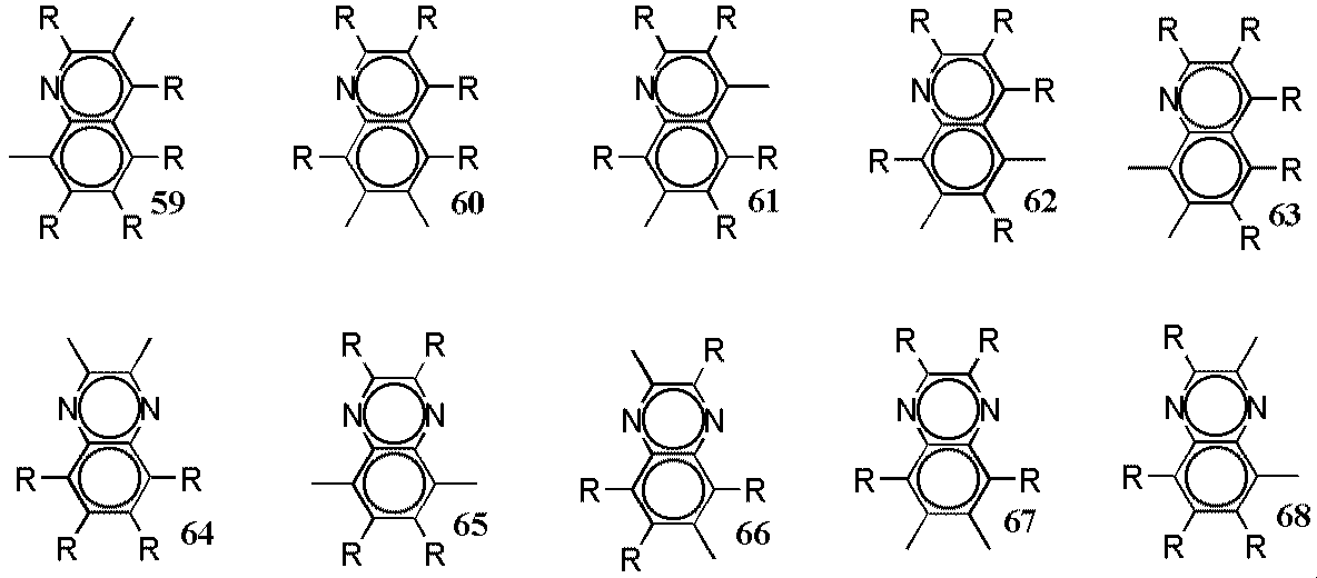
ヘテロ原子として、窒素を含む2価の複素環化合物基;ピリジンージイル基(下図の式39〜44)、ジアザフェニレン基(下図の式45〜48)、キノリンジイル基(下図の式49〜63)、キノキサリンジイル基(下図の式64〜68)、アクリジンジイル基(下図の式69〜72)、ビピリジルジイル基(下図の式73〜75)、フェナントロリンジイル基(下図の式76〜78)、など。
ヘテロ原子としてけい素、窒素、硫黄、セレンなどを含みフルオレン構造を有する基(下図の式79〜93)。
ヘテロ原子としてけい素、窒素、硫黄、セレンなどを含む5員環複素環化合物基:(下図の式94〜98)が挙げられる。
ヘテロ原子としてけい素、窒素、硫黄、セレンなどを含む5員環縮合複素環化合物基:(下図の式99〜108)が挙げられる。
ヘテロ原子としてけい素、窒素、硫黄、セレンなどを含む5員環複素環化合物基でそのヘテロ原子のα位で結合し2量体やオリゴマーになっている基:(下図の式109〜110)が挙げられる。
ヘテロ原子としてけい素、窒素、硫黄、セレンなどを含む5員環複素環化合物基でそのヘテロ原子のα位でフェニル基に結合している基:(下図の式111〜117)が挙げられる。
In the present invention, the divalent heterocyclic compound group means the remaining atomic group obtained by removing two hydrogen atoms from the heterocyclic compound, and the carbon number is usually 4 to 60, preferably 4 to 20. The carbon number of the divalent heterocyclic compound group does not include the carbon number of the substituent.
Here, a heterocyclic compound is an organic compound having a cyclic structure in which the elements constituting the ring include not only carbon atoms but also heteroatoms such as oxygen, sulfur, nitrogen, phosphorus, and boron in the ring. Say.
Examples of the divalent heterocyclic compound group include the following.
A divalent heterocyclic compound group containing nitrogen as a hetero atom; a pyridine-diyl group (formulas 39 to 44 in the following diagram), a diazaphenylene group (formulas 45 to 48 in the diagram below), a quinoline diyl group (formulas 49 to 63 in the diagram below), A quinoxaline diyl group (formulas 64 to 68 in the lower figure), an acridine diyl group (formulas 69 to 72 in the lower figure), a bipyridyldiyl group (formulas 73 to 75 in the lower figure), a phenanthroline diyl group (formulas 76 to 78 in the lower figure), and the like.
Groups having a fluorene structure containing silicon, nitrogen, sulfur, selenium and the like as a hetero atom (formulas 79 to 93 in the following figure).
5-membered ring heterocyclic compound groups containing silicon, nitrogen, sulfur, selenium and the like as a hetero atom: (Formulas 94 to 98 in the following figure).
5-membered ring condensed heterocyclic compound groups containing silicon, nitrogen, sulfur, selenium and the like as a hetero atom: (Formulas 99 to 108 in the following figure).
A 5-membered heterocyclic compound group containing silicon, nitrogen, sulfur, selenium, etc. as a heteroatom and bonded in the α-position of the heteroatom to form a dimer or oligomer: (Formulas 109 to 110 in the figure below) Is mentioned.
Examples are groups having a 5-membered ring heterocyclic compound group containing silicon, nitrogen, sulfur, selenium and the like as a hetero atom and bonded to a phenyl group at the α-position of the hetero atom (formulas 111 to 117 in the following figure).
ここで、Rは、それぞれ独立に、水素原子、アルキル基、アルコキシ基、アルキルチオ基、アルキルシリル基、アルキルアミノ基、アリール基、アリールオキシ基、アリールアルキル基、アリールアルコキシ基、アリールアルケニル基、アリールアルキニル基、アリールアミノ基、複素環化合物基およびシアノ基からなる群から選ばれる基を示す。上記の例において、1つの構造式中に複数のRを有しているが、それらは同一であってもよいし、異なる基であってもよく、それぞれ独立に選択される。Ar1が複数の置換基を有する場合、それらは同一であってもよいし、それぞれ異なっていてもよい。溶媒への溶解性を高めるためには、置換基を1つ以上有していることが好ましく、また置換基を含めた繰り返し単位の形状の対称性が少ないことが好ましい。 Here, each R is independently a hydrogen atom, alkyl group, alkoxy group, alkylthio group, alkylsilyl group, alkylamino group, aryl group, aryloxy group, arylalkyl group, arylalkoxy group, arylalkenyl group, aryl A group selected from the group consisting of an alkynyl group, an arylamino group, a heterocyclic compound group and a cyano group is shown. In the above example, a plurality of Rs are contained in one structural formula, but they may be the same or different groups, and are independently selected. When Ar 1 has a plurality of substituents, they may be the same or different. In order to increase the solubility in a solvent, it is preferable to have one or more substituents, and it is preferable that the symmetry of the shape of the repeating unit including the substituents is small.
アルキル基は、直鎖、分岐または環状のいずれでもよく、炭素数は通常1〜20程度であり、具体的には、メチル基、エチル基、プロピル基、i−プロピル基、ブチル基、 i−ブチル基、t−ブチル基、ペンチル基、ヘキシル基、シクロヘキシル基、ヘプチル基、オクチル基、2−エチルヘキシル基、ノニル基、デシル基、3,7−ジメチルオクチル基、ラウリル基などが挙げられ、ペンチル基、ヘキシル基、オクチル基、2−エチルヘキシル基、デシル基、3,7−ジメチルオクチル基が好ましい。 The alkyl group may be linear, branched or cyclic, and usually has about 1 to 20 carbon atoms. Specifically, methyl group, ethyl group, propyl group, i-propyl group, butyl group, i- Examples include butyl group, t-butyl group, pentyl group, hexyl group, cyclohexyl group, heptyl group, octyl group, 2-ethylhexyl group, nonyl group, decyl group, 3,7-dimethyloctyl group, lauryl group, and the like. Group, hexyl group, octyl group, 2-ethylhexyl group, decyl group and 3,7-dimethyloctyl group are preferred.
アルコキシ基は、直鎖、分岐または環状のいずれでもよく、炭素数は通常1〜20程度であり、具体的には、メトキシ基、エトキシ基、プロピルオキシ基、 i−プロピルオキシ基、ブトキシ基、 i−ブトキシ基、t−ブトキシ基、ペンチルオキシ基、ヘキシルオキシ基、シクロヘキシルオキシ基、ヘプチルオキシ基、オクチルオキシ基、2−エチルヘキシルオキシ基、ノニルオキシ基、デシルオキシ基、3,7−ジメチルオクチルオキシ基、ラウリルオキシ基などが挙げられ、ペンチルオキシ基、ヘキシルオキシ基、オクチルオキシ基、2−エチルヘキシルオキシ基、デシルオキシ基、3,7−ジメチルオクチルオキシ基が好ましい。 The alkoxy group may be linear, branched or cyclic, and usually has about 1 to 20 carbon atoms. Specifically, the methoxy group, ethoxy group, propyloxy group, i-propyloxy group, butoxy group, i-butoxy group, t-butoxy group, pentyloxy group, hexyloxy group, cyclohexyloxy group, heptyloxy group, octyloxy group, 2-ethylhexyloxy group, nonyloxy group, decyloxy group, 3,7-dimethyloctyloxy group Lauryloxy group, and the like, and pentyloxy group, hexyloxy group, octyloxy group, 2-ethylhexyloxy group, decyloxy group, and 3,7-dimethyloctyloxy group are preferable.
アルキルチオ基は、直鎖、分岐または環状のいずれでもよく、炭素数は通常1〜20程度であり、具体的には、メチルチオ基、エチルチオ基、プロピルチオ基、 i−プロピルチオ基、ブチルチオ基、 i−ブチルチオ基、t−ブチルチオ基、ペンチルチオ基、ヘキシルチオ基、シクロヘキシルチオ基、ヘプチルチオ基、オクチルチオ基、2−エチルヘキシルチオ基、ノニルチオ基、デシルチオ基、3,7−ジメチルオクチルチオ基、ラウリルチオ基などが挙げられ、ペンチルチオ基、ヘキシルチオ基、オクチルチオ基、2−エチルヘキシルチオ基、デシルチオ基、3,7−ジメチルオクチルチオ基が好ましい。 The alkylthio group may be linear, branched or cyclic, and usually has about 1 to 20 carbon atoms. Specifically, methylthio group, ethylthio group, propylthio group, i-propylthio group, butylthio group, i- Examples include butylthio group, t-butylthio group, pentylthio group, hexylthio group, cyclohexylthio group, heptylthio group, octylthio group, 2-ethylhexylthio group, nonylthio group, decylthio group, 3,7-dimethyloctylthio group, laurylthio group, etc. A pentylthio group, a hexylthio group, an octylthio group, a 2-ethylhexylthio group, a decylthio group, and a 3,7-dimethyloctylthio group are preferred.
アルキルシリル基は、直鎖、分岐または環状のいずれでもよく、炭素数は通常1〜60程度であり、具体的には、メチルシリル基、エチルシリル基、プロピルシリル基、 i−プロピルシリル基、ブチルシリル基、i−ブチルシリル基、t−ブチルシリル基、ペンチルシリル基、ヘキシルシリル基、シクロヘキシルシリル基、ヘプチルシリル基、オクチルシリル基、2−エチルヘキシルシリル基、ノニルシリル基、デシルシリル基、3,7−ジメチルオクチルシリル基、ラウリルシリル基、トリメチルシリル基、エチルジメチルシリル基、プロピルジメチルシリル基、 i−プロピルジメチルシリル基、ブチルジメチルシリル基、t−ブチルジメチルシリル基、ペンチルジメチルシリル基、ヘキシルジメチルシリル基、ヘプチルジメチルシリル基、オクチルジメチルシリル基、2−エチルヘキシル−ジメチルシリル基、ノニルジメチルシリル基、デシルジメチルシリル基、3,7−ジメチルオクチル−ジメチルシリル基、ラウリルジメチルシリル基などが挙げられ、ペンチルシリル基、ヘキシルシリル基、オクチルシリル基、2−エチルヘキシルシリル基、デシルシリル基、3,7−ジメチルオクチルシリル基、ペンチルジメチルシリル基、ヘキシルジメチルシリル基、オクチルジメチルシリル基、2−エチルヘキシル−ジメチルシリル基、デシルジメチルシリル基、3,7−ジメチルオクチル−ジメチルシリル基が好ましい。 The alkylsilyl group may be linear, branched or cyclic, and usually has about 1 to 60 carbon atoms. Specifically, methylsilyl group, ethylsilyl group, propylsilyl group, i-propylsilyl group, butylsilyl group I-butylsilyl group, t-butylsilyl group, pentylsilyl group, hexylsilyl group, cyclohexylsilyl group, heptylsilyl group, octylsilyl group, 2-ethylhexylsilyl group, nonylsilyl group, decylsilyl group, 3,7-dimethyloctylsilyl Group, laurylsilyl group, trimethylsilyl group, ethyldimethylsilyl group, propyldimethylsilyl group, i-propyldimethylsilyl group, butyldimethylsilyl group, t-butyldimethylsilyl group, pentyldimethylsilyl group, hexyldimethylsilyl group, heptyldimethyl Cyril Group, octyldimethylsilyl group, 2-ethylhexyl-dimethylsilyl group, nonyldimethylsilyl group, decyldimethylsilyl group, 3,7-dimethyloctyl-dimethylsilyl group, lauryldimethylsilyl group, etc., pentylsilyl group, hexyl Silyl group, octylsilyl group, 2-ethylhexylsilyl group, decylsilyl group, 3,7-dimethyloctylsilyl group, pentyldimethylsilyl group, hexyldimethylsilyl group, octyldimethylsilyl group, 2-ethylhexyl-dimethylsilyl group, decyldimethyl A silyl group and a 3,7-dimethyloctyl-dimethylsilyl group are preferred.
アルキルアミノ基は、直鎖、分岐または環状のいずれでもよく、モノアルキルアミノ基でもジアルキルアミノ基でもよく、炭素数は通常1〜40程度であり、具体的には、メチルアミノ基、ジメチルアミノ基、エチルアミノ基、ジエチルアミノ基、プロピルアミノ基、 i−プロピルアミノ基、ブチルアミノ基、 i−ブチルアミノ基、t−ブチルアミノ基、ペンチルアミノ基、ヘキシルアミノ基、シクロヘキシルアミノ基、ヘプチルアミノ基、オクチルアミノ基、2−エチルヘキシルアミノ基、ノニルアミノ基、デシルアミノ基、3,7−ジメチルオクチルアミノ基、ラウリルアミノ基などが挙げられ、ペンチルアミノ基、ヘキシルアミノ基、オクチルアミノ基、2−エチルヘキシルアミノ基、デシルアミノ基、3,7−ジメチルオクチルアミノ基が好ましい。 The alkylamino group may be linear, branched or cyclic, and may be a monoalkylamino group or a dialkylamino group, and usually has about 1 to 40 carbon atoms. Specifically, a methylamino group or a dimethylamino group , Ethylamino group, diethylamino group, propylamino group, i-propylamino group, butylamino group, i-butylamino group, t-butylamino group, pentylamino group, hexylamino group, cyclohexylamino group, heptylamino group, Examples include octylamino group, 2-ethylhexylamino group, nonylamino group, decylamino group, 3,7-dimethyloctylamino group, laurylamino group, pentylamino group, hexylamino group, octylamino group, 2-ethylhexylamino group , Decylamino group, 3,7-dimethyloctyla A mino group is preferred.
アリール基は、芳香族炭化水素から、水素原子1個を除いた原子団であり、炭素数は通常6〜60程度であり、具体的には、フェニル基、C1〜C12アルコキシフェニル基(C1〜C12は、炭素数1〜12であることを示す。以下も同様である。)、C1〜C12アルキルフェニル基、1−ナフチル基、2−ナフチル基などが例示され、 C1〜C12アルコキシフェニル基、C1〜C12アルキルフェニル基が好ましい。 The aryl group is an atomic group obtained by removing one hydrogen atom from an aromatic hydrocarbon, and usually has about 6 to 60 carbon atoms. Specifically, a phenyl group, a C 1 to C 12 alkoxyphenyl group ( C 1 -C 12 indicate that it has 1 to 12 carbon atoms, and the same applies to the following.), C 1 -C 12 alkylphenyl group, 1-naphthyl group, 2-naphthyl group, etc. 1 -C 12 alkoxyphenyl group, C 1 -C 12 alkylphenyl group are preferred.
アリールオキシ基は、炭素数は通常6〜60程度であり、具体的には、フェノキシ基、C1〜C12アルコキシフェノキシ基、C1〜C12アルキルフェノキシ基、1−ナフチルオキシ基、2−ナフチルオキシ基などが例示され、 C1〜C12アルコキシフェノキシ基、C1〜C12アルキルフェノキシ基が好ましい。 The aryloxy group usually has about 6 to 60 carbon atoms, and specifically includes a phenoxy group, a C 1 to C 12 alkoxyphenoxy group, a C 1 to C 12 alkylphenoxy group, a 1-naphthyloxy group, 2- naphthyloxy group and the like, C 1 -C 12 alkoxy phenoxy group, a C 1 -C 12 alkylphenoxy group are preferable.
アリールアルキル基は、炭素数は通常7〜60程度であり、具体的には、フェニル−C1〜C12アルキル基、C1〜C12アルコキシフェニル−C1〜C12アルキル基、C1〜C12アルキルフェニル−C1〜C12アルキル基、1−ナフチル−C1〜C12アルキル基、2−ナフチル−C1〜C12アルキル基などが例示され、C1〜C12アルコキシフェニル−C1〜C12アルキル基、C1〜C12アルキルフェニル−C1〜C12アルキル基が好ましい。 Arylalkyl group has a carbon number of usually about 7 to 60, specifically, phenyl -C 1 -C 12 alkyl group, C 1 -C 12 alkoxyphenyl -C 1 -C 12 alkyl group, C 1 ~ C 12 alkylphenyl-C 1 -C 12 alkyl group, 1-naphthyl-C 1 -C 12 alkyl group, 2-naphthyl-C 1 -C 12 alkyl group and the like are exemplified, and C 1 -C 12 alkoxyphenyl-C 1 -C 12 alkyl group, C 1 -C 12 alkylphenyl -C 1 -C 12 alkyl group are preferable.
アリールアルコキシ基は、炭素数は通常7〜60程度であり、具体的には、フェニル−C1〜C12アルコキシ基、C1〜C12アルコキシフェニル−C1〜C12アルコキシ基、C1〜C12アルキルフェニル−C1〜C12アルコキシ基、1−ナフチル−C1〜C12アルコキシ基、2−ナフチル−C1〜C12アルコキシ基などが例示され、C1〜C12アルコキシフェニル−C1〜C12アルコキシ基、C1〜C12アルキルフェニル−C1〜C12アルコキシ基が好ましい。 Arylalkoxy group has a carbon number of usually about 7 to 60, specifically, phenyl -C 1 -C 12 alkoxy group, C 1 -C 12 alkoxyphenyl -C 1 -C 12 alkoxy group, C 1 ~ C 12 alkylphenyl-C 1 -C 12 alkoxy group, 1-naphthyl-C 1 -C 12 alkoxy group, 2-naphthyl-C 1 -C 12 alkoxy group and the like are exemplified, and C 1 -C 12 alkoxyphenyl-C 1 -C 12 alkoxy group, C 1 -C 12 alkylphenyl -C 1 -C 12 alkoxy group are preferable.
アリールアミノ基は、炭素数は通常6〜60程度であり、フェニルアミノ基、ジフェニルアミノ基、C1〜C12アルコキシフェニルアミノ基、ジ(C1〜C12アルコキシフェニル)アミノ基、ジ(C1〜C12アルキルフェニル)アミノ基、1−ナフチルアミノ基、2−ナフチルアミノ基などが例示され、C1〜C12アルキルフェニルアミノ基、ジ(C1〜C12アルキルフェニル)アミノ基が好ましい。 Arylamino group has a carbon number of usually about 6 to 60, phenylamino group, diphenylamino group, C 1 -C 12 alkoxyphenyl amino group, di (C 1 -C 12 alkoxyphenyl) amino group, di (C 1 -C 12 alkylphenyl) amino groups, 1-naphthylamino group, a 2-naphthylamino group and the like, C 1 -C 12 alkylphenyl group, di (C 1 -C 12 alkylphenyl) amino group are preferable .
1価の複素環化合物基とは、複素環化合物から水素原子1個を除いた残りの原子団をいい、炭素数は通常4〜60程度であり、具体的には、チエニル基、C1〜C12アルキルチエニル基、ピロリル基、フリル基、ピリジル基、C1〜C12アルキルピリジル基などが例示され、チエニル基、C1〜C12アルキルチエニル基、ピリジル基、C1〜C12アルキルピリジル基が好ましい。 The monovalent heterocyclic compound group means a remaining atomic group obtained by removing one hydrogen atom from a heterocyclic compound, and usually has about 4 to 60 carbon atoms. Specifically, a thienyl group, a C 1- C 12 alkyl thienyl group, a pyrrolyl group, a furyl group, a pyridyl group, a C 1 -C 12 alkyl pyridyl group are thienyl group, C 1 -C 12 alkyl thienyl group, a pyridyl group, C 1 -C 12 alkyl pyridyl Groups are preferred.
Rの例のうち、アルキル鎖を含む置換基においては、それらは直鎖、分岐枝付きまたは環状のいずれかまたはそれらの組み合わせであってもよく、直鎖でない場合、例えば、イソアミル基、2−エチルヘキシル基、3,7−ジメチルオクチル基、シクロヘキシル基、4−C1〜C12アルキルシクロヘキシル基などが例示される。高分子蛍光体の溶媒への溶解性を高めるためには、Ar1の置換基のうちの1つ以上に環状または分岐のあるアルキル鎖が含まれることが好ましい。また、アルキル鎖の一部の炭素原子がヘテロ原子で置き換えられていてもよく、それらのヘテロ原子としては、酸素原子、硫黄原子、窒素原子などが例示される。さらに、Rの例のうち、アリール基や複素環化合物基をその一部に含む場合は、それらがさらに1つ以上の置換基を有していてもよい。 Among the examples of R, in the substituents containing an alkyl chain, they may be linear, branched or cyclic, or a combination thereof, and when they are not linear, for example, an isoamyl group, 2- Examples include ethylhexyl group, 3,7-dimethyloctyl group, cyclohexyl group, 4-C 1 -C 12 alkylcyclohexyl group and the like. In order to increase the solubility of the polymeric fluorescent substance in a solvent, it is preferable that one or more of Ar 1 substituents include a cyclic or branched alkyl chain. Moreover, some carbon atoms of the alkyl chain may be replaced with heteroatoms, and examples of these heteroatoms include oxygen atoms, sulfur atoms, nitrogen atoms and the like. Furthermore, among the examples of R, when an aryl group or a heterocyclic compound group is included as a part thereof, they may further have one or more substituents.
上記式(1)において、nは0または1である。上記式(1)におけるR1、R2は、それぞれ独立に水素原子、アルキル基、アリール基、1価の複素環化合物基およびシアノ基からなる群から選ばれる基を示す。 In the above formula (1), n is 0 or 1. R 1 and R 2 in the above formula (1) each independently represent a group selected from the group consisting of a hydrogen atom, an alkyl group, an aryl group, a monovalent heterocyclic compound group, and a cyano group.
R1、R2が、水素原子またはシアノ基以外の置換基である場合について述べると、アルキル基は、直鎖、分岐または環状のいずれでもよく、炭素数は通常1〜20程度であり、具体的には、メチル基、エチル基、プロピル基、ブチル基、ペンチル基、ヘキシル基、ヘプチル基、オクチル基、ノニル基、デシル基、ラウリル基などが挙げられ、メチル基、エチル基、ペンチル基、ヘキシル基、ヘプチル基、オクチル基が好ましい。 The case where R 1 and R 2 are a substituent other than a hydrogen atom or a cyano group will be described. The alkyl group may be linear, branched or cyclic, and usually has about 1 to 20 carbon atoms. Specifically, a methyl group, an ethyl group, a propyl group, a butyl group, a pentyl group, a hexyl group, a heptyl group, an octyl group, a nonyl group, a decyl group, a lauryl group, and the like can be mentioned. A methyl group, an ethyl group, a pentyl group, A hexyl group, a heptyl group, and an octyl group are preferable.
アリール基は、炭素数は通常6〜60程度であり、具体的には、フェニル基、C1〜C12アルコキシフェニル基(C1〜C12は、炭素数1〜12であることを示す。以下も同様である。)、C1〜C12アルキルフェニル基、1−ナフチル基、2−ナフチル基などが例示され、 C1〜C12アルコキシフェニル基、C1〜C12アルキルフェニル基が好ましい。 The aryl group usually has about 6 to 60 carbon atoms, and specifically includes a phenyl group and a C 1 to C 12 alkoxyphenyl group (C 1 to C 12 have 1 to 12 carbon atoms). The same shall apply hereinafter.), C 1 -C 12 alkylphenyl group, 1-naphthyl group, 2-naphthyl group and the like are exemplified, and C 1 -C 12 alkoxyphenyl group, C 1 -C 12 alkylphenyl group are preferred. .
1価の複素環化合物基は、炭素数は通常4〜60程度であり、具体的には、チエニル基、C1〜C12アルキルチエニル基、ピロリル基、フリル基、ピリジル基、C1〜C12アルキルピリジル基などが例示され、チエニル基、C1〜C12アルキルチエニル基、ピリジル基、C1〜C12アルキルピリジル基が好ましい。 The monovalent heterocyclic compound group usually has about 4 to 60 carbon atoms, and specifically includes thienyl group, C 1 to C 12 alkyl thienyl group, pyrrolyl group, furyl group, pyridyl group, C 1 to C 12 is alkylpyridyl like Jill group is thienyl group, C 1 -C 12 alkyl thienyl group, a pyridyl group, a C 1 -C 12 alkyl pyridyl group are preferable.
また、高分子蛍光体の末端基は、重合活性基がそのまま残っていると、素子にしたときの発光特性や寿命が低下する可能性があるので、安定な基で保護されていても良い。主鎖の共役構造と連続した共役結合を有しているものが好ましく、例えば、ビニレン基を介してアリール基または複素環化合物基と結合している構造が例示される。具体的には、特開平9−45478号公報の化10に記載の置換基等が例示される。 Further, the terminal group of the polymeric fluorescent substance may be protected with a stable group, since if the polymerization active group remains as it is, there is a possibility that the light emission characteristics and lifetime when the device is made will be reduced. Those having a conjugated bond continuous with the conjugated structure of the main chain are preferred, and examples thereof include a structure bonded to an aryl group or a heterocyclic compound group via a vinylene group. Specific examples include substituents described in Chemical formula 10 of JP-A-9-45478.
本発明において、高分子蛍光体の合成法としては、主鎖にビニレン基を有する場合には、例えば特開平5−202355号公報に記載の方法が挙げられる。すなわち、ジアルデヒド化合物とジホスホニウム塩化合物とのWittig反応による重合、ジビニル化合物とジハロゲン化合物とのもしくはビニルハロゲン化合物単独でのHeck反応による重合、ジアルデヒド化合物とジ亜燐酸エステル化合物とのHorner−Wadsworth−Emmons法による重合、ハロゲン化メチル基を2つ有する化合物の脱ハロゲン化水素法による重縮合、スルホニウム塩基を2つ有する化合物のスルホニウム塩分解法による重縮合、ジアルデヒド化合物とジアセトニトリル化合物とのKnoevenagel反応による重合などの方法、ジアルデヒド化合物のMcMurry反応による重合などの方法が例示される。 In the present invention, as a method for synthesizing a polymeric fluorescent substance, when a main chain has a vinylene group, for example, a method described in JP-A-5-202355 can be mentioned. That is, polymerization by a Wittig reaction of a dialdehyde compound and a diphosphonium salt compound, polymerization by a Heck reaction of a divinyl compound and a dihalogen compound or a vinyl halogen compound alone, Horner-Wadsworth of a dialdehyde compound and a diphosphite compound -Polymerization by Emmons method, polycondensation of compounds having two halogenated methyl groups by dehydrohalogenation method, polycondensation of compounds having two sulfonium bases by sulfonium salt decomposition method, Knoevenagel of dialdehyde compound and diacetonitrile compound Examples include a method such as polymerization by reaction and a method such as polymerization by McMurry reaction of a dialdehyde compound.
また、主鎖にビニレン基を有しない場合には、例えば該当するモノマーからSuzukiカップリング反応により重合する方法、Grignard反応により重合する方法、Ni(0)触媒により重合する方法、FeCl3等の酸化剤により重合する方法、電気化学的に酸化重合する方法、あるいは適当な脱離基を有する中間体高分子の分解による方法などが例示される。 In the case where the main chain does not have a vinylene group, for example, a method of polymerizing from a corresponding monomer by a Suzuki coupling reaction, a method of polymerizing by a Grignard reaction, a method of polymerizing by a Ni (0) catalyst, an oxidation of FeCl 3 or the like Examples include a method of polymerizing with an agent, a method of electrochemically oxidatively polymerizing, a method of decomposing an intermediate polymer having an appropriate leaving group, and the like.
なお、該高分子蛍光体は、蛍光特性や電荷輸送特性を損なわない範囲で、式(1)で示される繰り返し単位以外の繰り返し単位を含んでいてもよい。また、式(1)で示される繰り返し単位や他の繰り返し単位が、非共役の単位で連結されていてもよいし、繰り返し単位にそれらの非共役部分が含まれていてもよい。結合構造としては、以下に示すもの、以下に示すものとビニレン基を組み合わせたもの、および以下に示すもののうち2つ以上を組み合わせたものなどが例示される。ここで、Rは前記のものと同じ置換基から選ばれる基であり、Arは炭素数6〜60個の炭化水素基を示す。 In addition, this polymeric fluorescent substance may contain repeating units other than the repeating unit shown by Formula (1) in the range which does not impair a fluorescence characteristic and a charge transport characteristic. In addition, the repeating unit represented by the formula (1) and other repeating units may be linked by a non-conjugated unit, or the repeating unit may contain those non-conjugated parts. Examples of the bonding structure include those shown below, combinations of the following and vinylene groups, and combinations of two or more of the following. Here, R is a group selected from the same substituents as described above, and Ar represents a hydrocarbon group having 6 to 60 carbon atoms.
また、該高分子蛍光体は、ランダム、ブロックまたはグラフト共重合体であってもよいし、それらの中間的な構造を有する高分子、例えばブロック性を帯びたランダム共重合体であってもよい。蛍光の量子収率の高い高分子蛍光体を得る観点からは完全なランダム共重合体よりブロック性を帯びたランダム共重合体やブロックまたはグラフト共重合体が好ましい。主鎖に枝分かれがあり、末端部が3つ以上ある場合やデンドリマーも含まれる。 The polymeric fluorescent substance may be a random, block or graft copolymer, or may be a polymer having an intermediate structure thereof, for example, a random copolymer having a block property. . From the viewpoint of obtaining a polymer fluorescent substance having a high fluorescence quantum yield, a random copolymer having a block property and a block or graft copolymer are preferable to a complete random copolymer. A case in which the main chain is branched and there are three or more terminal portions and dendrimers are also included.
また、薄膜からの発光を利用するので該高分子蛍光体は、固体状態で蛍光を有するものが好適に用いられる。
該高分子蛍光体に対する溶媒のなかで良溶媒としては、クロロホルム、塩化メチレン、ジクロロエタン、テトラヒドロフラン、トルエン、キシレン、メシチレン、デカリン、n−ブチルベンゼンなどが例示される。高分子蛍光体の構造や分子量にもよるが、通常はこれらの溶媒に0.1重量%以上溶解させることができる。
Moreover, since light emission from a thin film is used, the polymer fluorescent substance preferably has fluorescence in a solid state.
Among the solvents for the polymeric fluorescent substance, examples of good solvents include chloroform, methylene chloride, dichloroethane, tetrahydrofuran, toluene, xylene, mesitylene, decalin, n-butylbenzene and the like. Although depending on the structure and molecular weight of the polymeric fluorescent substance, it can usually be dissolved in these solvents in an amount of 0.1% by weight or more.
該高分子蛍光体は、分子量がポリスチレン換算で1×10³〜1×10⁷であり、それらの繰り返し単位の合計数は、繰り返し構造やその割合によっても変わる。成膜性の点から一般には繰り返し構造の合計数が、好ましくは20〜10000、さらに好ましくは30〜10000、特に好ましくは50〜5000である。 The polymeric fluorescent substance has a molecular weight of 1 × 10 3 to 1 × 10 7 in terms of polystyrene, and the total number of these repeating units varies depending on the repeating structure and its ratio. In general, the total number of repeating structures is preferably 20 to 10,000, more preferably 30 to 10,000, and particularly preferably 50 to 5,000 from the viewpoint of film formability.
これらの高分子蛍光体を有機EL素子の発光材料として用いる場合、その純度が発光特性に影響を与えるため、重合前のモノマーを蒸留、昇華精製、再結晶等の方法で精製したのちに重合することが好ましく、また合成後、再沈精製、クロマトグラフィーによる分別等の純化処理をすることが好ましい。 When these polymeric fluorescent substances are used as a light emitting material for organic EL devices, the purity affects the light emission characteristics. Therefore, the prepolymerized monomer is polymerized after being purified by methods such as distillation, sublimation purification, and recrystallization. It is preferable to carry out a purification treatment such as reprecipitation purification and fractionation by chromatography after the synthesis.
次に本発明の高分子蛍光体溶液について説明する。
本発明の高分子蛍光体溶液は、固体状態で蛍光を有し、ポリスチレン換算の数平均分子量が1×10³〜1×10⁷であり、上記式(1)で示される繰り返し単位を1種類以上含む高分子蛍光体を0.1重量%以上5重量%以下含み、含有する水分量が1000ppm(重量)以下、好ましくは500ppm(重量)以下、更に好ましくは50ppm(重量)以下である。本発明の高分子蛍光体溶液の含水率は、カールフィッシャー法で測定することができる。
また、本発明の高分子蛍光体溶液のなかで、含有する水分量が1000ppm(重量)以下の溶媒に高分子蛍光体を溶解して製造されるものが好ましい。
本発明の高分子蛍光体溶液を得る方法としては、該溶液の含水率が1000ppm(重量)以下になる方法であれば特に限定されない。
例えば、(a)あらかじめ、高分子蛍光体溶液の含水量が1000ppm(重量)以下になるように含水量を調整した高分子蛍光体と溶媒を混合して高分子蛍光体溶液を得る方法、(b)高分子蛍光体溶液を公知の種々の方法で乾燥する方法などが挙げられる。
上記(b)の方法の中では、含水率が1000ppm(重量)以下である溶媒を用いることが好ましく、本発明の特定の含水率の高分子蛍光体と含水率が1000ppm以下(重量)である溶媒を用いる方法がさらに好ましい。
Next, the polymeric fluorescent substance solution of the present invention will be described.
The polymeric fluorescent substance solution of the present invention has fluorescence in a solid state, has a polystyrene-equivalent number average molecular weight of 1 × 10 3 to 1 × 10 7 , and one type of repeating unit represented by the above formula (1). The polymeric fluorescent substance containing the above is contained in an amount of 0.1 wt% or more and 5 wt% or less, and the water content is 1000 ppm (wt) or less, preferably 500 ppm (wt) or less, more preferably 50 ppm (wt) or less. The water content of the polymeric fluorescent substance solution of the present invention can be measured by the Karl Fischer method.
In addition, among the polymer phosphor solutions of the present invention, those prepared by dissolving the polymer phosphor in a solvent having a water content of 1000 ppm (weight) or less are preferable.
The method for obtaining the polymeric fluorescent substance solution of the present invention is not particularly limited as long as the water content of the solution is 1000 ppm (weight) or less.
For example, (a) a method of obtaining a polymer phosphor solution by mixing a polymer phosphor whose water content is adjusted in advance so that the water content of the polymer phosphor solution is 1000 ppm (weight) or less, and a solvent, b) A method of drying the polymer fluorescent substance solution by various known methods.
In the method (b), it is preferable to use a solvent having a water content of 1000 ppm (weight) or less, and the polymer fluorescent substance having a specific water content of the present invention and a water content of 1000 ppm or less (weight). A method using a solvent is more preferable.
次に、本発明の高分子LEDについて説明する。
本発明の高分子LEDは、少なくとも一方が透明または半透明である一対の陽極および陰極からなる電極間に、少なくとも発光層を有し、該発光層が本発明の高分子蛍光体を用いてなることを特徴とする。
また本発明の高分子LEDは、少なくとも一方が透明または半透明である一対の陽極および陰極からなる電極間に、少なくとも発光層を有し、該発光層が本発明の高分子蛍光体溶液を用いて作成されたことを特徴とする。
Next, the polymer LED of the present invention will be described.
The polymer LED of the present invention has at least a light emitting layer between electrodes composed of a pair of an anode and a cathode, at least one of which is transparent or translucent, and the light emitting layer is formed using the polymer phosphor of the present invention. It is characterized by that.
The polymer LED of the present invention has at least a light emitting layer between electrodes composed of a pair of an anode and a cathode, at least one of which is transparent or translucent, and the light emitting layer uses the polymer phosphor solution of the present invention. It was created by
また、本発明の高分子LEDとしては、陰極と発光層との間に、電子輸送層を設けた高分子LED、陽極と発光層との間に、正孔輸送層を設けた高分子LED、陰極と発光層との間に、電子輸送層を設け、かつ陽極と発光層との間に、正孔輸送層を設けた高分子LED等が挙げられる。
例えば、具体的には、以下のa)〜d)の構造が例示される。
a)陽極/発光層/陰極
b)陽極/正孔輸送層/発光層/陰極
c)陽極/発光層/電子輸送層/陰極
d)陽極/正孔輸送層/発光層/電子輸送層/陰極
(ここで、/は各層が隣接して積層されていることを示す。以下同じ。)
In addition, as the polymer LED of the present invention, a polymer LED having an electron transport layer provided between the cathode and the light emitting layer, a polymer LED having a hole transport layer provided between the anode and the light emitting layer, Examples include a polymer LED in which an electron transport layer is provided between the cathode and the light emitting layer, and a hole transport layer is provided between the anode and the light emitting layer.
For example, the following structures a) to d) are specifically exemplified.
a) Anode / light emitting layer / cathode b) Anode / hole transport layer / light emitting layer / cathode c) Anode / light emitting layer / electron transport layer / cathode d) Anode / hole transport layer / light emitting layer / electron transport layer / cathode (Here, / indicates that each layer is laminated adjacently. The same shall apply hereinafter.)
ここで、発光層とは、発光する機能を有する層であり、正孔輸送層とは、正孔を輸送する機能を有する層であり、電子輸送層とは、電子を輸送する機能を有する層である。なお、電子輸送層と正孔輸送層を総称して電荷輸送層と呼ぶ。
発光層、正孔輸送層、電子輸送層は、それぞれ独立に2層以上用いてもよい。
Here, the light emitting layer is a layer having a function of emitting light, the hole transporting layer is a layer having a function of transporting holes, and the electron transporting layer is a layer having a function of transporting electrons. It is. The electron transport layer and the hole transport layer are collectively referred to as a charge transport layer.
Two or more light emitting layers, hole transport layers, and electron transport layers may be used independently.
また、電極に隣接して設けた電荷輸送層のうち、電極からの電荷注入効率を改善する機能を有し、素子の駆動電圧を下げる効果を有するものは、特に電荷注入層(正孔注入層、電子注入層)と一般に呼ばれることがある。 Further, among the charge transport layers provided adjacent to the electrodes, those having a function of improving the charge injection efficiency from the electrodes and having the effect of lowering the driving voltage of the element are particularly charge injection layers (hole injection layers). , An electron injection layer).
さらに電極との密着性向上や電極からの電荷注入の改善のために、電極に隣接して前記の電荷注入層又は膜厚2nm以下の絶縁層を設けてもよく、また、界面の密着性向上や混合の防止等のために電荷輸送層や発光層の界面に薄いバッファー層を挿入してもよい。
積層する層の順番や数、および各層の厚さについては、発光効率や素子寿命を勘案して適宜用いることができる。
Further, in order to improve adhesion with the electrode and charge injection from the electrode, the charge injection layer or an insulating layer having a thickness of 2 nm or less may be provided adjacent to the electrode, and the adhesion at the interface may be improved. In order to prevent mixing, a thin buffer layer may be inserted at the interface between the charge transport layer and the light emitting layer.
The order and number of layers to be laminated, and the thickness of each layer can be appropriately used in consideration of light emission efficiency and element lifetime.
本発明において、電荷注入層(電子注入層、正孔注入層)を設けた高分子LEDとしては、陰極に隣接して電荷注入層を設けた高分子LED、陽極に隣接して電荷注入層を設けた高分子LEDが挙げられる。
例えば、具体的には、以下のe)〜p)の構造が挙げられる。
e)陽極/電荷注入層/発光層/陰極
f)陽極/発光層/電荷注入層/陰極
g)陽極/電荷注入層/発光層/電荷注入層/陰極
h)陽極/電荷注入層/正孔輸送層/発光層/陰極
i)陽極/正孔輸送層/発光層/電荷注入層/陰極
j)陽極/電荷注入層/正孔輸送層/発光層/電荷注入層/陰極
k)陽極/電荷注入層/発光層/電荷輸送層/陰極
l)陽極/発光層/電子輸送層/電荷注入層/陰極
m)陽極/電荷注入層/発光層/電子輸送層/電荷注入層/陰極
n)陽極/電荷注入層/正孔輸送層/発光層/電荷輸送層/陰極
o)陽極/正孔輸送層/発光層/電子輸送層/電荷注入層/陰極
p)陽極/電荷注入層/正孔輸送層/発光層/電子輸送層/電荷注入層/陰極
In the present invention, a polymer LED provided with a charge injection layer (electron injection layer, hole injection layer) includes a polymer LED provided with a charge injection layer adjacent to the cathode, and a charge injection layer adjacent to the anode. The provided polymer LED is mentioned.
For example, the following structures e) to p) are specifically mentioned.
e) Anode / charge injection layer / light emitting layer / cathode
f) Anode / light emitting layer / charge injection layer / cathode
g) Anode / charge injection layer / light emitting layer / charge injection layer / cathode
h) Anode / charge injection layer / hole transport layer / light emitting layer / cathode
i) Anode / hole transport layer / light emitting layer / charge injection layer / cathode
j) Anode / charge injection layer / hole transport layer / light emitting layer / charge injection layer / cathode
k) Anode / charge injection layer / light emitting layer / charge transport layer / cathode
l) Anode / light-emitting layer / electron transport layer / charge injection layer / cathode
m) Anode / charge injection layer / light emitting layer / electron transport layer / charge injection layer / cathode
n) Anode / charge injection layer / hole transport layer / light emitting layer / charge transport layer / cathode o) Anode / hole transport layer / light emitting layer / electron transport layer / charge injection layer / cathode p) Anode / charge injection layer / Hole transport layer / light emitting layer / electron transport layer / charge injection layer / cathode
電荷注入層の具体的な例としては、導電性高分子を含む層、陽極と正孔輸送層との間に設けられ、陽極材料と正孔輸送層に含まれる正孔輸送材料との中間の値のイオン化ポテンシャルを有する材料を含む層、陰極と電子輸送層との間に設けられ、陰極材料と電子輸送層に含まれる電子輸送材料との中間の値の電子親和力を有する材料を含む層などが例示される。 Specific examples of the charge injection layer include a layer containing a conductive polymer, an anode and a hole transport layer provided between the anode material and the hole transport material included in the hole transport layer. A layer containing a material having an ionization potential of a value, a layer provided between a cathode and an electron transport layer, and a layer containing a material having an electron affinity of an intermediate value between the cathode material and the electron transport material contained in the electron transport layer, etc. Is exemplified.
上記電荷注入層が導電性高分子を含む層の場合、該導電性高分子の電気伝導度は、10-5S/cm以上103以下であることが好ましく、発光画素間のリーク電流を小さくするためには、10-5S/cm以上102以下がより好ましく、10-5S/cm以上101以下がさらに好ましい。
通常は該導電性高分子の電気伝導度を10-5S/cm以上103以下とするために、該導電性高分子に適量のイオンをドープする。
When the charge injection layer is a layer containing a conductive polymer, the electrical conductivity of the conductive polymer is preferably 10 −5 S / cm or more and 10 3 or less, and the leakage current between the light emitting pixels is reduced. In order to achieve this, 10 −5 S / cm to 10 2 is more preferable, and 10 −5 S / cm to 10 1 is more preferable.
Usually, in order to make the electric conductivity of the conductive polymer 10 −5 S / cm or more and 10 3 or less, the conductive polymer is doped with an appropriate amount of ions.
ドープするイオンの種類は、正孔注入層であればアニオン、電子注入層であればカチオンである。アニオンの例としては、ポリスチレンスルホン酸イオン、アルキルベンゼンスルホン酸イオン、樟脳スルホン酸イオンなどが例示され、カチオンの例としては、リチウムイオン、ナトリウムイオン、カリウムイオン、テトラブチルアンモニウムイオンなどが例示される。
電荷注入層の膜厚としては、例えば1nm〜100nmであり、2nm〜50nmが好ましい。
The type of ions to be doped is an anion for the hole injection layer and a cation for the electron injection layer. Examples of anions include polystyrene sulfonate ions, alkylbenzene sulfonate ions, camphor sulfonate ions, and examples of cations include lithium ions, sodium ions, potassium ions, tetrabutylammonium ions, and the like.
The thickness of the charge injection layer is, for example, 1 nm to 100 nm, and preferably 2 nm to 50 nm.
電荷注入層に用いる材料は、電極や隣接する層の材料との関係で適宜選択すればよく、ポリアニリンおよびその誘導体、ポリチオフェンおよびその誘導体、ポリフェニレンビニレンおよびその誘導体、ポリチエニレンビニレンおよびその誘導体などの導電性高分子、金属フタロシアニン(銅フタロシアニンなど)、カーボンなどが例示される。 The material used for the charge injection layer may be appropriately selected in relation to the electrode and the material of the adjacent layer, such as polyaniline and its derivatives, polythiophene and its derivatives, polyphenylene vinylene and its derivatives, polythienylene vinylene and its derivatives, etc. Examples thereof include conductive polymers, metal phthalocyanines (such as copper phthalocyanine), and carbon.
膜厚2nm以下の絶縁層は電荷注入を容易にする機能を有するものである。上記絶縁層の材料としては、金属フッ化物、金属酸化物、有機絶縁材料等が挙げられる。膜厚2nm以下の絶縁層を設けた高分子LEDとしては、陰極に隣接して膜厚2nm以下の絶縁層を設けた高分子LED、陽極に隣接して膜厚2nm以下の絶縁層を設けた高分子LEDが挙げられる。 An insulating layer having a thickness of 2 nm or less has a function of facilitating charge injection. Examples of the material for the insulating layer include metal fluorides, metal oxides, and organic insulating materials. As the polymer LED provided with the insulating layer having a thickness of 2 nm or less, the polymer LED provided with the insulating layer having a thickness of 2 nm or less adjacent to the cathode, or the insulating layer having a thickness of 2 nm or less provided adjacent to the anode. Polymer LED is mentioned.
具体的には、例えば、以下のq)〜ab)の構造が挙げられる。
q)陽極/膜厚2nm以下の絶縁層/発光層/陰極
r)陽極/発光層/膜厚2nm以下の絶縁層/陰極
s)陽極/膜厚2nm以下の絶縁層/発光層/膜厚2nm以下の絶縁層/陰極
t)陽極/膜厚2nm以下の絶縁層/正孔輸送層/発光層/陰極
u)陽極/正孔輸送層/発光層/膜厚2nm以下の絶縁層/陰極
v)陽極/膜厚2nm以下の絶縁層/正孔輸送層/発光層/膜厚2nm以下の絶縁層/陰極
w)陽極/膜厚2nm以下の絶縁層/発光層/電子輸送層/陰極
x)陽極/発光層/電子輸送層/膜厚2nm以下の絶縁層/陰極
y)陽極/膜厚2nm以下の絶縁層/発光層/電子輸送層/膜厚2nm以下の絶縁層/陰極
z)陽極/膜厚2nm以下の絶縁層/正孔輸送層/発光層/電子輸送層/陰極
aa)陽極/正孔輸送層/発光層/電子輸送層/膜厚2nm以下の絶縁層/陰極
ab)陽極/膜厚2nm以下の絶縁層/正孔輸送層/発光層/電子輸送層/膜厚2nm以下の絶縁層/陰極
Specific examples include the following structures q) to ab).
q) Anode / insulating layer with a thickness of 2 nm or less / light emitting layer / cathode r) Anode / light emitting layer / insulating layer with a thickness of 2 nm or less / cathode s) Anode / insulating layer with a thickness of 2 nm or less / light emitting layer / film thickness 2 nm Insulating layer / cathode t) Anode / insulating layer with a thickness of 2 nm or less / hole transport layer / light emitting layer / cathode
u) Anode / hole transport layer / light emitting layer / insulating layer with a thickness of 2 nm or less / cathode
v) Anode / insulating layer with a thickness of 2 nm or less / hole transport layer / light emitting layer / insulating layer with a thickness of 2 nm or less / cathode
w) Anode / insulating layer with a thickness of 2 nm or less / light emitting layer / electron transport layer / cathode
x) Anode / light-emitting layer / electron transport layer / insulating layer with a thickness of 2 nm or less / cathode
y) Anode / insulating layer with a thickness of 2 nm or less / light emitting layer / electron transport layer / insulating layer with a thickness of 2 nm or less / cathode
z) Anode / insulating layer with a thickness of 2 nm or less / hole transport layer / light emitting layer / electron transport layer / cathode
aa) Anode / hole transport layer / light emitting layer / electron transport layer / insulating layer with a thickness of 2 nm or less / cathode
ab) Anode / insulating layer with a thickness of 2 nm or less / hole transporting layer / light emitting layer / electron transporting layer / insulating layer with a thickness of 2 nm or less / cathode
発光層作成の際に、これらの有機溶媒可溶性の高分子蛍光体を用いることにより、溶液から成膜する場合、この溶液を塗布後乾燥により溶媒を除去するだけでよく、また電荷輸送材料や発光材料を混合した場合においても同様な手法が適用でき、製造上非常に有利である。溶液からの成膜方法としては、スピンコート法、キャスティング法、マイクログラビアコート法、グラビアコート法、バーコート法、ロールコート法、ワイアーバーコート法、ディップコート法、スプレーコート法、スクリーン印刷法、フレキソ印刷法、オフセット印刷法、インクジェットプリント法等の塗布法を用いることができる。 When forming a film from a solution by using these organic solvent-soluble polymeric fluorescent substances at the time of forming a light emitting layer, it is only necessary to remove the solvent by drying after applying this solution. The same technique can be applied even when the materials are mixed, which is very advantageous in manufacturing. As a film forming method from a solution, a spin coating method, a casting method, a micro gravure coating method, a gravure coating method, a bar coating method, a roll coating method, a wire bar coating method, a dip coating method, a spray coating method, a screen printing method, Application methods such as a flexographic printing method, an offset printing method, and an ink jet printing method can be used.
発光層の膜厚としては、用いる材料によって最適値が異なり、駆動電圧と発光効率が適度な値となるように選択すればよいが、例えば1nmから1μmであり、好ましくは2nm〜500nmであり、さらに好ましくは5nm〜200nmである。 As the film thickness of the light emitting layer, the optimum value varies depending on the material to be used, and it may be selected so that the drive voltage and the light emission efficiency are appropriate values. For example, the thickness is 1 nm to 1 μm, preferably 2 nm to 500 nm. More preferably, it is 5 nm-200 nm.
本発明の高分子LEDにおいては、発光層に上記高分子蛍光体以外の発光材料を用いても良いし、それらを混合して使用してもよい。また、本願発明の高分子LEDにおいては、発光層に上記高分子蛍光体以外の発光材料を混合して使用してもよい。
該発光材料としては、公知のものが使用できる。低分子化合物では、例えば、ナフタレン誘導体、アントラセンもしくはその誘導体、ペリレンもしくはその誘導体、ポリメチン系、キサンテン系、クマリン系、シアニン系などの色素類、8−ヒドロキシキノリンもしくはその誘導体の金属錯体、芳香族アミン、テトラフェニルシクロペンタジエンもしくはその誘導体、またはテトラフェニルブタジエンもしくはその誘導体などを用いることができる。
具体的には、例えば特開昭57−51781号、同59−194393号公報に記載されているもの等、公知のものが使用可能である。
In the polymer LED of the present invention, a light emitting material other than the polymer fluorescent substance may be used for the light emitting layer, or a mixture thereof may be used. Moreover, in the polymer LED of the present invention, a light emitting material other than the polymer fluorescent substance may be mixed and used in the light emitting layer.
As the light emitting material, known materials can be used. Examples of low molecular weight compounds include naphthalene derivatives, anthracene or derivatives thereof, perylene or derivatives thereof, polymethine-based, xanthene-based, coumarin-based, cyanine-based pigments, 8-hydroxyquinoline or metal complexes of derivatives thereof, aromatic amines, and the like. , Tetraphenylcyclopentadiene or a derivative thereof, or tetraphenylbutadiene or a derivative thereof can be used.
Specifically, for example, known ones such as those described in JP-A-57-51781 and 59-194393 can be used.
本発明の高分子LEDが正孔輸送層を有する場合、使用される正孔輸送材料としては、ポリビニルカルバゾールもしくはその誘導体、ポリシランもしくはその誘導体、側鎖に芳香族アミンを有するポリシロキサン誘導体、ピラゾリン誘導体、アリールアミン誘導体、スチルベン誘導体、トリフェニルジアミン誘導体、ポリアニリンもしくはその誘導体、ポリチオフェンもしくはその誘導体、ポリ(p−フェニレンビニレン)もしくはその誘導体、またはポリ(2,5−チエニレンビニレン)もしくはその誘導体が例示される。 When the polymer LED of the present invention has a hole transport layer, the hole transport material used includes polyvinyl carbazole or a derivative thereof, polysilane or a derivative thereof, a polysiloxane derivative having an aromatic amine in a side chain, and a pyrazoline derivative. , Arylamine derivatives, stilbene derivatives, triphenyldiamine derivatives, polyaniline or derivatives thereof, polythiophene or derivatives thereof, poly (p-phenylene vinylene) or derivatives thereof, or poly (2,5-thienylene vinylene) or derivatives thereof Is done.
具体的には、該正孔輸送材料として、特開昭63−70257号公報、同63−175860号公報、特開平2−135359号公報、同2−135361号公報、同2−209988号公報、同3−37992号公報、同3−152184号公報に記載されているもの等が例示される。 Specifically, as the hole transport material, JP-A-63-70257, JP-A-63-175860, JP-A-2-135359, JP-A-2-135361, JP-A-2-209998, Examples described in JP-A-3-37992 and JP-A-3-152184 are exemplified.
これらの中で、正孔輸送層に用いる正孔輸送材料として、ポリビニルカルバゾールもしくはその誘導体、ポリシランもしくはその誘導体、側鎖もしくは主鎖に芳香族アミン化合物基を有するポリシロキサン誘導体、ポリアニリンもしくはその誘導体、ポリチオフェンもしくはその誘導体、ポリ(p−フェニレンビニレン)もしくはその誘導体、またはポリ(2,5−チエニレンビニレン)もしくはその誘導体等の高分子正孔輸送材料が好ましく、さらに好ましくはポリビニルカルバゾールもしくはその誘導体、ポリシランもしくはその誘導体、側鎖もしくは主鎖に芳香族アミンを有するポリシロキサン誘導体である。低分子の正孔輸送材料の場合には、高分子バインダーに分散させて用いることが好ましい。 Among these, as a hole transport material used for the hole transport layer, polyvinyl carbazole or a derivative thereof, polysilane or a derivative thereof, a polysiloxane derivative having an aromatic amine compound group in a side chain or a main chain, polyaniline or a derivative thereof, Preferred is a polymer hole transport material such as polythiophene or a derivative thereof, poly (p-phenylene vinylene) or a derivative thereof, or poly (2,5-thienylene vinylene) or a derivative thereof, more preferably polyvinyl carbazole or a derivative thereof, Polysilane or a derivative thereof, or a polysiloxane derivative having an aromatic amine in the side chain or main chain. In the case of a low-molecular hole transport material, it is preferably used by being dispersed in a polymer binder.
ポリビニルカルバゾールもしくはその誘導体は、例えばビニルモノマーからカチオン重合またはラジカル重合によって得られる。 Polyvinylcarbazole or a derivative thereof is obtained, for example, from a vinyl monomer by cation polymerization or radical polymerization.
ポリシランもしくはその誘導体としては、ケミカル・レビュー(Chem.Rev.)第89巻、1359頁(1989年)、英国特許GB2300196号公開明細書に記載の化合物等が例示される。合成方法もこれらに記載の方法を用いることができるが、特にキッピング法が好適に用いられる。 Examples of polysilane or derivatives thereof include compounds described in Chem. Rev. 89, 1359 (1989) and GB 2300196 published specification. As the synthesis method, the methods described in these can be used, but the Kipping method is particularly preferably used.
ポリシロキサンもしくはその誘導体は、シロキサン骨格構造には正孔輸送性がほとんどないので、側鎖または主鎖に上記低分子正孔輸送材料の構造を有するものが好適に用いられる。特に正孔輸送性の芳香族アミンを側鎖または主鎖に有するものが例示される。 Since polysiloxane or a derivative thereof has almost no hole transporting property in the siloxane skeleton structure, those having the structure of the low molecular hole transporting material in the side chain or main chain are preferably used. Particularly, those having a hole transporting aromatic amine in the side chain or main chain are exemplified.
正孔輸送層の成膜の方法に制限はないが、低分子正孔輸送材料では、高分子バインダーとの混合溶液からの成膜による方法が例示される。また、高分子正孔輸送材料では、溶液からの成膜による方法が例示される。 Although there is no restriction | limiting in the film-forming method of a positive hole transport layer, In the low molecular hole transport material, the method by the film-forming from a mixed solution with a polymer binder is illustrated. In the case of a polymer hole transport material, a method of film formation from a solution is exemplified.
溶液からの成膜に用いる溶媒としては、正孔輸送材料を溶解させるものであれば特に制限はない。該溶媒として、クロロホルム、塩化メチレン、ジクロロエタン等の塩素系溶媒、テトラヒドロフラン等のエーテル系溶媒、トルエン、キシレン等の芳香族炭化水素系溶媒、アセトン、メチルエチルケトン等のケトン系溶媒、酢酸エチル、酢酸ブチル、エチルセルソルブアセテート等のエステル系溶媒が例示される。 The solvent used for film formation from a solution is not particularly limited as long as it can dissolve a hole transport material. Examples of the solvent include chlorine solvents such as chloroform, methylene chloride, and dichloroethane; ether solvents such as tetrahydrofuran; aromatic hydrocarbon solvents such as toluene and xylene; ketone solvents such as acetone and methyl ethyl ketone; ethyl acetate, butyl acetate, An ester solvent such as ethyl cellosolve acetate is exemplified.
溶液からの成膜方法としては、溶液からのスピンコート法、キャスティング法、マイクログラビアコート法、グラビアコート法、バーコート法、ロールコート法、ワイアーバーコート法、ディップコート法、スプレーコート法、スクリーン印刷法、フレキソ印刷法、オフセット印刷法、インクジェットプリント法等の塗布法を用いることができる。 Examples of film formation methods from solution include spin coating from solution, casting method, micro gravure coating method, gravure coating method, bar coating method, roll coating method, wire bar coating method, dip coating method, spray coating method, screen Coating methods such as a printing method, a flexographic printing method, an offset printing method, and an inkjet printing method can be used.
混合する高分子バインダーとしては、電荷輸送を極度に阻害しないものが好ましく、また可視光に対する吸収が強くないものが好適に用いられる。該高分子バインダーとして、ポリカーボネート、ポリアクリレート、ポリメチルアクリレート、ポリメチルメタクリレート、ポリスチレン、ポリ塩化ビニル、ポリシロキサン等が例示される。 As the polymer binder to be mixed, those not extremely disturbing charge transport are preferable, and those showing no strong absorption against visible light are suitably used. Examples of the polymer binder include polycarbonate, polyacrylate, polymethyl acrylate, polymethyl methacrylate, polystyrene, polyvinyl chloride, and polysiloxane.
正孔輸送層の膜厚としては、用いる材料によって最適値が異なり、駆動電圧と発光効率が適度な値となるように選択すればよいが、少なくともピンホールが発生しないような厚さが必要であり、あまり厚いと、素子の駆動電圧が高くなり好ましくない。従って、該正孔輸送層の膜厚としては、例えば1nmから1μmであり、好ましくは2nm〜500nmであり、さらに好ましくは5nm〜200nmである。 The film thickness of the hole transport layer differs depending on the material used, and may be selected so that the drive voltage and the light emission efficiency are appropriate. However, at least a thickness that does not cause pinholes is required. If it is too thick, the driving voltage of the element becomes high, which is not preferable. Therefore, the film thickness of the hole transport layer is, for example, 1 nm to 1 μm, preferably 2 nm to 500 nm, and more preferably 5 nm to 200 nm.
本発明の高分子LEDが電子輸送層を有する場合、使用される電子輸送材料としては公知のものが使用でき、オキサジアゾール誘導体、アントラキノジメタンもしくはその誘導体、ベンゾキノンもしくはその誘導体、ナフトキノンもしくはその誘導体、アントラキノンもしくはその誘導体、テトラシアノアンスラキノジメタンもしくはその誘導体、フルオレノン誘導体、ジフェニルジシアノエチレンもしくはその誘導体、ジフェノキノン誘導体、または8−ヒドロキシキノリンもしくはその誘導体の金属錯体等が例示される。 When the polymer LED of the present invention has an electron transport layer, known electron transport materials can be used, such as oxadiazole derivatives, anthraquinodimethane or derivatives thereof, benzoquinone or derivatives thereof, naphthoquinone or derivatives thereof. Examples include a derivative, anthraquinone or a derivative thereof, tetracyanoanthraquinodimethane or a derivative thereof, a fluorenone derivative, diphenyldicyanoethylene or a derivative thereof, a diphenoquinone derivative, or a metal complex of 8-hydroxyquinoline or a derivative thereof.
具体的には、特開昭63−70257号公報、同63−175860号公報、特開平2−135359号公報、同2−135361号公報、同2−209988号公報、同3−37992号公報、同3−152184号公報に記載されているもの等が例示される。 Specifically, JP-A-63-70257, JP-A-63-175860, JP-A-2-135359, JP-A-2-135361, JP-A-2-20988, JP-A-3-37992, The thing etc. which are described in the same 3-152184 gazette are illustrated.
これらのうち、オキサジアゾール誘導体、ベンゾキノンもしくはその誘導体、アントラキノンもしくはその誘導体、または8−ヒドロキシキノリンもしくはその誘導体の金属錯体が好ましく、2−(4−ビフェニリル)−5−(4−t−ブチルフェニル)−1,3,4−オキサジアゾール、ベンゾキノン、アントラキノン、トリス(8−キノリノール)アルミニウムがさらに好ましい。 Of these, oxadiazole derivatives, benzoquinone or derivatives thereof, anthraquinones or derivatives thereof, or metal complexes of 8-hydroxyquinoline or derivatives thereof are preferred, and 2- (4-biphenylyl) -5- (4-t-butylphenyl) ) -1,3,4-oxadiazole, benzoquinone, anthraquinone, and tris (8-quinolinol) aluminum are more preferable.
電子輸送層の成膜法としては特に制限はないが、低分子電子輸送材料では、粉末からの真空蒸着法、または溶液もしくは溶融状態からの成膜による方法が、高分子電子輸送材料では溶液または溶融状態からの成膜による方法がそれぞれ例示される。溶液または溶融状態からの成膜時には、高分子バインダーを併用してもよい。 There are no particular restrictions on the method for forming the electron transport layer, but for low molecular weight electron transport materials, vacuum deposition from powder, or by film formation from a solution or molten state, and for polymer electron transport materials, solution or Each method is exemplified by film formation from a molten state. In film formation from a solution or a molten state, a polymer binder may be used in combination.
溶液からの成膜に用いる溶媒としては、電子輸送材料および/または高分子バインダーを溶解させるものであれば特に制限はない。該溶媒として、クロロホルム、塩化メチレン、ジクロロエタン等の塩素系溶媒、テトラヒドロフラン等のエーテル系溶媒、トルエン、キシレン等の芳香族炭化水素系溶媒、アセトン、メチルエチルケトン等のケトン系溶媒、酢酸エチル、酢酸ブチル、エチルセルソルブアセテート等のエステル系溶媒が例示される。 The solvent used for film formation from a solution is not particularly limited as long as it can dissolve an electron transport material and / or a polymer binder. Examples of the solvent include chlorine solvents such as chloroform, methylene chloride, and dichloroethane; ether solvents such as tetrahydrofuran; aromatic hydrocarbon solvents such as toluene and xylene; ketone solvents such as acetone and methyl ethyl ketone; ethyl acetate, butyl acetate, An ester solvent such as ethyl cellosolve acetate is exemplified.
溶液または溶融状態からの成膜方法としては、スピンコート法、キャスティング法、マイクログラビアコート法、グラビアコート法、バーコート法、ロールコート法、ワイアーバーコート法、ディップコート法、スプレーコート法、スクリーン印刷法、フレキソ印刷法、オフセット印刷法、インクジェットプリント法等の塗布法を用いることができる。 Examples of film formation methods from a solution or a molten state include spin coating, casting, micro gravure coating, gravure coating, bar coating, roll coating, wire bar coating, dip coating, spray coating, and screen. Coating methods such as a printing method, a flexographic printing method, an offset printing method, and an inkjet printing method can be used.
混合する高分子バインダーとしては、電荷輸送を極度に阻害しないものが好ましく、また、可視光に対する吸収が強くないものが好適に用いられる。該高分子バインダーとして、ポリ(N−ビニルカルバゾール)、ポリアニリンもしくはその誘導体、ポリチオフェンもしくはその誘導体、ポリ(p−フェニレンビニレン)もしくはその誘導体、ポリ(2,5−チエニレンビニレン)もしくはその誘導体、ポリカーボネート、ポリアクリレート、ポリメチルアクリレート、ポリメチルメタクリレート、ポリスチレン、ポリ塩化ビニル、またはポリシロキサンなどが例示される。 As the polymer binder to be mixed, those not extremely disturbing charge transport are preferable, and those not strongly absorbing visible light are suitably used. As the polymer binder, poly (N-vinylcarbazole), polyaniline or a derivative thereof, polythiophene or a derivative thereof, poly (p-phenylenevinylene) or a derivative thereof, poly (2,5-thienylenevinylene) or a derivative thereof, polycarbonate , Polyacrylate, polymethyl acrylate, polymethyl methacrylate, polystyrene, polyvinyl chloride, or polysiloxane.
電子輸送層の膜厚としては、用いる材料によって最適値が異なり、駆動電圧と発光効率が適度な値となるように選択すればよいが、少なくともピンホールが発生しないような厚さが必要であり、あまり厚いと、素子の駆動電圧が高くなり好ましくない。従って、該電子輸送層の膜厚としては、例えば1nmから1μmであり、好ましくは2nm〜500nmであり、さらに好ましくは5nm〜200nmである。 The film thickness of the electron transport layer differs depending on the material used, and may be selected so that the drive voltage and the light emission efficiency are appropriate. However, at least a thickness that does not cause pinholes is required. If the thickness is too thick, the driving voltage of the element increases, which is not preferable. Therefore, the thickness of the electron transport layer is, for example, 1 nm to 1 μm, preferably 2 nm to 500 nm, and more preferably 5 nm to 200 nm.
本発明の高分子LEDを形成する基板は、電極を形成し、導電性高分子からなる層を塗布により形成し、電解ドープの際に変化しないものであればよく、例えばガラス、プラスチック、高分子フィルム、シリコン基板などが例示される。不透明な基板の場合には、反対の電極が透明または半透明であることが好ましい。 The substrate for forming the polymer LED of the present invention may be any substrate as long as it forms an electrode, a layer made of a conductive polymer is formed by coating, and does not change during electrolytic doping, for example, glass, plastic, polymer A film, a silicon substrate, etc. are illustrated. In the case of an opaque substrate, the opposite electrode is preferably transparent or translucent.
本発明において、陽極側が透明または半透明であることが好ましいが、該陽極の材料としては、導電性の金属酸化物膜、半透明の金属薄膜等が用いられる。具体的には、酸化インジウム、酸化亜鉛、酸化スズ、およびそれらの複合体であるインジウム・スズ・オキサイド(ITO)、インジウム・亜鉛・オキサイド等からなる導電性ガラスを用いて作成された膜(NESAなど)や、金、白金、銀、銅等が用いられ、ITO、インジウム・亜鉛・オキサイド、酸化スズが好ましい。作製方法としては、真空蒸着法、スパッタリング法、イオンプレーティング法、メッキ法等が挙げられる。また、該陽極として、ポリアニリンもしくはその誘導体、ポリチオフェンもしくはその誘導体などの有機の透明導電膜を用いてもよい。
陽極の膜厚は、光の透過性と電気伝導度とを考慮して、適宜選択することができるが、例えば10nmから10μmであり、好ましくは20nm〜1μmであり、さらに好ましくは50nm〜500nmである。
また、陽極上に、電荷注入を容易にするために、フタロシアニン誘導体、導電性高分子、カーボンなどからなる層、あるいは金属酸化物や金属フッ化物、有機絶縁材料等からなる平均膜厚2nm以下の層を設けてもよい。
In the present invention, the anode side is preferably transparent or translucent, but as the material of the anode, a conductive metal oxide film, a translucent metal thin film, or the like is used. Specifically, indium oxide, zinc oxide, tin oxide, and a composite film made of conductive glass made of indium / tin / oxide (ITO), indium / zinc / oxide, etc. (NESA) Etc.), gold, platinum, silver, copper and the like are used, and ITO, indium / zinc / oxide, and tin oxide are preferable. Examples of the production method include a vacuum deposition method, a sputtering method, an ion plating method, a plating method, and the like. Further, an organic transparent conductive film such as polyaniline or a derivative thereof, polythiophene or a derivative thereof may be used as the anode.
The film thickness of the anode can be appropriately selected in consideration of light transmittance and electric conductivity, and is, for example, 10 nm to 10 μm, preferably 20 nm to 1 μm, more preferably 50 nm to 500 nm. is there.
Further, in order to facilitate charge injection on the anode, a layer made of a phthalocyanine derivative, a conductive polymer, carbon or the like, or an average film thickness of 2 nm or less made of a metal oxide, a metal fluoride, an organic insulating material or the like. A layer may be provided.
本発明の高分子LEDで用いる陰極の材料としては、仕事関数の小さい材料が好ましい。例えば、リチウム、ナトリウム、カリウム、ルビジウム、セシウム、ベリリウム、マグネシウム、カルシウム、ストロンチウム、バリウム、アルミニウム、スカンジウム、バナジウム、亜鉛、イットリウム、インジウム、セリウム、サマリウム、ユーロピウム、テルビウム、イッテルビウムなどの金属、およびそれらのうち2つ以上の合金、あるいはそれらのうち1つ以上と、金、銀、白金、銅、マンガン、チタン、コバルト、ニッケル、タングステン、錫のうち1つ以上との合金、グラファイトまたはグラファイト層間化合物等が用いられる。合金の例としては、マグネシウム−銀合金、マグネシウム−インジウム合金、マグネシウム−アルミニウム合金、インジウム−銀合金、リチウム−アルミニウム合金、リチウム−マグネシウム合金、リチウム−インジウム合金、カルシウム−アルミニウム合金などが挙げられる。陰極を2層以上の積層構造としてもよい。
陰極の膜厚は、電気伝導度や耐久性を考慮して、適宜選択することができるが、例えば10nmから10μmであり、好ましくは20nm〜1μmであり、さらに好ましくは50nm〜500nmである。
As a material of the cathode used in the polymer LED of the present invention, a material having a small work function is preferable. For example, metals such as lithium, sodium, potassium, rubidium, cesium, beryllium, magnesium, calcium, strontium, barium, aluminum, scandium, vanadium, zinc, yttrium, indium, cerium, samarium, europium, terbium, ytterbium, and their Two or more of these alloys, or an alloy of one or more of them and one or more of gold, silver, platinum, copper, manganese, titanium, cobalt, nickel, tungsten, tin, graphite or graphite intercalation compound, etc. Is used. Examples of the alloy include magnesium-silver alloy, magnesium-indium alloy, magnesium-aluminum alloy, indium-silver alloy, lithium-aluminum alloy, lithium-magnesium alloy, lithium-indium alloy, calcium-aluminum alloy, and the like. The cathode may have a laminated structure of two or more layers.
The thickness of the cathode can be appropriately selected in consideration of electric conductivity and durability, but is, for example, 10 nm to 10 μm, preferably 20 nm to 1 μm, and more preferably 50 nm to 500 nm.
陰極の作製方法としては、真空蒸着法、スパッタリング法、また金属薄膜を熱圧着するラミネート法等が用いられる。また、陰極と有機物層との間に、導電性高分子からなる層、あるいは金属酸化物や金属フッ化物、有機絶縁材料等からなる平均膜厚2nm以下の層を設けても良く、陰極作製後、該高分子LEDを保護する保護層を装着していてもよい。該高分子LEDを長期安定的に用いるためには、素子を外部から保護するために、保護層および/または保護カバーを装着することが好ましい。 As a method for producing the cathode, a vacuum deposition method, a sputtering method, a laminating method in which a metal thin film is thermocompression bonded, or the like is used. Further, a layer made of a conductive polymer or a layer made of a metal oxide, metal fluoride, organic insulating material or the like having an average film thickness of 2 nm or less may be provided between the cathode and the organic layer. A protective layer for protecting the polymer LED may be attached. In order to use the polymer LED stably for a long period of time, it is preferable to attach a protective layer and / or protective cover in order to protect the element from the outside.
該保護層としては、高分子化合物、金属酸化物、金属フッ化物、金属ホウ化物などを用いることができる。また、保護カバーとしては、ガラス板、表面に低透水率処理を施したプラスチック板などを用いることができ、該カバーを熱効果樹脂や光硬化樹脂で素子基板と貼り合わせて密閉する方法が好適に用いられる。スペーサーを用いて空間を維持すれば、素子がキズつくのを防ぐことが容易である。該空間に窒素やアルゴンのような不活性なガスを封入すれば、陰極の酸化を防止することができ、さらに酸化バリウム等の乾燥剤を該空間内に設置することにより製造工程で吸着した水分が素子にタメージを与えるのを抑制することが容易となる。これらのうち、いずれか1つ以上の方策をとることが好ましい。 As the protective layer, a polymer compound, metal oxide, metal fluoride, metal boride and the like can be used. As the protective cover, a glass plate, a plastic plate having a low water permeability treatment on the surface, or the like can be used. Used for. If a space is maintained using a spacer, it is easy to prevent the element from being damaged. If an inert gas such as nitrogen or argon is sealed in the space, the cathode can be prevented from being oxidized, and moisture adsorbed in the manufacturing process by installing a desiccant such as barium oxide in the space. It becomes easy to suppress giving an image to an element. Among these, it is preferable to take any one or more measures.
本発明の高分子LEDを用いて面状の発光素子を得るためには、面状の陽極と陰極が重なり合うように配置すればよい。また、パターン状の発光を得るためには、前記面状の発光素子の表面にパターン状の窓を設けたマスクを設置する方法、非発光部の有機物層を極端に厚く形成し実質的に非発光とする方法、陽極または陰極のいずれか一方、または両方の電極をパターン状に形成する方法がある。更に、ドットマトリックス素子とするためには、陽極と陰極をともにストライプ状に形成して直交するように配置すればよい。複数の種類の発光色の異なる高分子蛍光体を塗り分ける方法や、カラーフィルターまたは蛍光変換フィルターを用いる方法により、部分カラー表示、マルチカラー表示が可能となる。
ドットマトリックス素子は、パッシブ駆動も可能であるし、TFTなどと組み合わせてアクティブ駆動しても良い。これらの表示素子は、コンピュータ、テレビ、携帯端末、携帯電話、カーナビゲーション、ビデオカメラのビューファインダーなどの表示装置として用いることができる。
さらに、前記面状の発光素子は、自発光薄型であり、液晶表示装置のバックライト用の面状光源、あるいは面状の照明用光源として好適に用いることができる。また、フレキシブルな基板を用いれば、曲面状の光源や表示装置としても使用できる。
In order to obtain a planar light emitting device using the polymer LED of the present invention, the planar anode and cathode may be arranged so as to overlap each other. In addition, in order to obtain pattern-like light emission, a method of installing a mask provided with a pattern-like window on the surface of the planar light-emitting element, an organic material layer of a non-light-emitting portion is formed extremely thick and substantially non- There are a method of emitting light and a method of forming either one of the anode or the cathode or both electrodes in a pattern. Further, in order to obtain a dot matrix element, both the anode and the cathode may be formed in a stripe shape and arranged so as to be orthogonal to each other. Partial color display and multi-color display are possible by a method of separately coating a plurality of types of polymeric fluorescent substances having different emission colors or a method using a color filter or a fluorescence conversion filter.
The dot matrix element can be driven passively, or can be actively driven in combination with a TFT or the like. These display elements can be used as display devices for computers, televisions, mobile terminals, mobile phones, car navigation systems, video camera viewfinders, and the like.
Furthermore, the planar light-emitting element is a self-luminous thin type, and can be suitably used as a planar light source for a backlight of a liquid crystal display device or a planar illumination light source. If a flexible substrate is used, it can be used as a curved light source or display device.
また本発明の高分子LEDの製造方法は、少なくとも一方が透明または半透明である一対の陽極および陰極からなる電極間に、少なくとも発光層を有し、該発光層が、固体状態で蛍光を有し、ポリスチレン換算の数平均分子量が1×10³〜1×10⁷である高分子蛍光体において、下記式(1)で示される繰り返し単位を1種類以上含む高分子蛍光体を含む高分子LEDの製造方法において、本発明の高分子蛍光体溶液を用いて該発光層を形成する工程を含むことを特徴とする。
発光層の形成方法については、前記した溶液からの成膜の方法を用いることができる。
The method for producing a polymer LED of the present invention has at least a light emitting layer between a pair of anodes and cathodes, at least one of which is transparent or translucent, and the light emitting layer has fluorescence in a solid state. And a polymer LED having a polystyrene-equivalent number average molecular weight of 1 × 10 3 to 1 × 10 7 , and a polymer LED comprising a polymer phosphor containing one or more repeating units represented by the following formula (1) The production method includes the step of forming the light emitting layer using the polymeric fluorescent substance solution of the present invention.
As a method for forming the light emitting layer, the above-described film forming method from a solution can be used.
以下、本発明をさらに詳細に説明するために実施例を示すが、本発明はこれらに限定されるものではない。
ここで、ポリスチレン換算の数平均分子量は、クロロホルムを溶媒として、ゲルパーミエーションクロマトグラフィー(GPC)により求めた。
EXAMPLES Examples will be shown below for illustrating the present invention in more detail, but the present invention is not limited to these examples.
Here, the number average molecular weight in terms of polystyrene was obtained by gel permeation chromatography (GPC) using chloroform as a solvent.
実施例1
<高分子蛍光体1の合成>
2、5−ビス(クロロメチル)−4’−(3,7−ジメチルオクチルオキシ)ビフェニル 1.83gと2−メチル−5−(3,7−ジメチルオクチル)―p−キシリレンジブロミド 1.63gと2−メトキシ−5−(2−エチルヘキシルオキシ)−p−キシリレンジクロリド 0.244gとを、脱水1,4−ジオキサン 660gに溶解した。この溶液を、20分間窒素バブリングすることで系内を窒素置換した後、窒素雰囲気中、95℃まで昇温した。この液に、あらかじめ、脱水1,4−ジオキサン 80gに、カリウム−t−ブトキシド 4.7gを溶かした溶液を、およそ10分間で滴下した。滴下後、97℃で2.5時間重合した。
重合後、重合液を50℃まで冷却した後、酢酸を加えて中和した。室温まで冷却した後、この重合液を、メタノール800g中にそそぎ込み、生成した沈殿を回収した。この沈殿を、エタノールで洗浄した後、減圧乾燥した。得られた重合体 1.5gを、THF 400gに溶解した。この溶液を、メタノール 800g中にそそぎ込み、生成した沈殿を回収した。この沈殿を、エタノールで洗浄した後、減圧乾燥して、重合体 1.4gを得た。この重合体を、高分子蛍光体1と呼ぶ。高分子蛍光体1のポリスチレン換算数平均分子量は、2x10⁵ であった。
Example 1
<Synthesis of polymeric fluorescent substance 1>
1.83 g of 2,5-bis (chloromethyl) -4 ′-(3,7-dimethyloctyloxy) biphenyl and 1.63 g of 2-methyl-5- (3,7-dimethyloctyl) -p-xylylene dibromide And 0.244 g of 2-methoxy-5- (2-ethylhexyloxy) -p-xylylene dichloride were dissolved in 660 g of dehydrated 1,4-dioxane. The system was purged with nitrogen by bubbling nitrogen for 20 minutes, and then heated to 95 ° C. in a nitrogen atmosphere. A solution prepared by dissolving 4.7 g of potassium t-butoxide in 80 g of dehydrated 1,4-dioxane in advance was added dropwise to this solution in about 10 minutes. After dropping, polymerization was carried out at 97 ° C. for 2.5 hours.
After the polymerization, the polymerization solution was cooled to 50 ° C. and then neutralized by adding acetic acid. After cooling to room temperature, the polymerization solution was poured into 800 g of methanol, and the generated precipitate was recovered. The precipitate was washed with ethanol and dried under reduced pressure. 1.5 g of the obtained polymer was dissolved in 400 g of THF. This solution was poured into 800 g of methanol, and the produced precipitate was recovered. This precipitate was washed with ethanol and then dried under reduced pressure to obtain 1.4 g of a polymer. This polymer is referred to as polymeric fluorescent substance 1. The number average molecular weight in terms of polystyrene of the polymeric fluorescent substance 1 was 2 × 10 5 .
<素子の作成および評価>
スパッタ法により150nmの厚みでITO膜を付けたガラス基板に、ポリ(3,4)エチレンジオキシチオフェン/ポリスチレンスルフォン酸(PEDOT:Bayer製、Bytron P TP AI 4083)の懸濁液を0.5μmメンブランフィルターで濾過した後、スピンコートにより70nmの厚みで成膜し、真空オーブンで120℃、1時間乾燥した。モレキュラシブスで乾燥したクロロホルム溶液に上記高分子蛍光体1を溶解して、0.4%溶液を調整した。このときのクロロホルム溶液の含水率をカールフィッシャー法で測定したところ1ppm(重量)以下であった。この液を用いて、上記PEDOTを塗布したITO膜付き基板上にスピンコートにより100nmの厚みで発光層を成膜した。さらに、これを減圧下80℃で1時間乾燥した後、陰極として、フッ化リチウムを約0.4nm相当、次いでカルシウムを40nm、さらにアルミニウムを70nm蒸着して、高分子LED素子を作製した。蒸着のときの真空度は、すべて8×10⁻⁶Torr以下であった。得られた素子に電圧を5.0V印加したところ、電流密度10mA/cm2 の電流が流れ、輝度550cd/m2の黄色のEL発光が観測された。このときの発光効率は5.6cd/Aであり、また素子の発光スペクトルは、560nmにピークを有していた。
<Creation and evaluation of device>
A suspension of poly (3,4) ethylenedioxythiophene / polystyrene sulfonic acid (PEDOT: manufactured by Bayer, Bytron P TP AI 4083) is 0.5 μm on a glass substrate having an ITO film with a thickness of 150 nm formed by sputtering. After filtration through a membrane filter, a film having a thickness of 70 nm was formed by spin coating and dried in a vacuum oven at 120 ° C. for 1 hour. The polymeric fluorescent substance 1 was dissolved in a chloroform solution dried by molecular sieves to prepare a 0.4% solution. When the water content of the chloroform solution at this time was measured by the Karl Fischer method, it was 1 ppm (weight) or less. Using this solution, a light emitting layer was formed to a thickness of 100 nm by spin coating on the ITO film-coated substrate coated with the PEDOT. Further, this was dried at 80 ° C. under reduced pressure for 1 hour, and then, as a cathode, lithium fluoride was equivalent to about 0.4 nm, then calcium was deposited by 40 nm, and aluminum was further deposited by 70 nm to produce a polymer LED element. The degree of vacuum at the time of vapor deposition was 8 × 10 −6 Torr or less. When a voltage of 5.0 V was applied to the obtained device, a current with a current density of 10 mA / cm 2 flowed, and yellow EL light emission with a luminance of 550 cd / m 2 was observed. The light emission efficiency at this time was 5.6 cd / A, and the light emission spectrum of the device had a peak at 560 nm.
比較例1
モレキュラシーブスで脱水したクロロホルム20gに純水を0.04g添加して、含水率2000ppm(重量)のクロロホルム溶液を調整した。モレキュラシーブスで脱水したクロロホルム溶液の代わりに、水を添加したクロロホルム溶液を用いる以外は実施例1と同様にして、高分子LED素子を作製した。得られた素子に電圧を5.0V印加したところ、電流密度5.6mA/cm2 の電流が流れ、輝度150cd/m2の黄色のEL発光が観測された。このときの発光効率は2.7cd/Aであった。
Comparative Example 1
0.04 g of pure water was added to 20 g of chloroform dehydrated with molecular sieves to prepare a chloroform solution having a water content of 2000 ppm (weight). A polymer LED device was produced in the same manner as in Example 1 except that a chloroform solution added with water was used instead of the chloroform solution dehydrated with molecular sieves. When a voltage of 5.0 V was applied to the obtained device, a current with a current density of 5.6 mA / cm 2 flowed, and yellow EL light emission with a luminance of 150 cd / m 2 was observed. The luminous efficiency at this time was 2.7 cd / A.
Claims (13)
−Ar1−(CR1=CR2)n− ・・・・・(1)
〔ここで、Ar1は、フェニレン基、ナフタレンジイル基、アントラセニレン基、ビフェニレン基、トリフェニレン基または縮合環化合物基であり、該フェニレン基、ナフタレンジイル基、アントラセニレン基、ビフェニレン基、トリフェニレン基及び縮合環化合物基は、アルキル基、アルコキシ基、アルキルチオ基、アルキルシリル基、アルキルアミノ基アリール基、アリールオキシ基、アリールアルキル基、アリールアルコキシ基、アリールアルケニル基、アリールアルキニル基、アリールアミノ基、複素環化合物基およびシアノ基からなる群から選ばれる1つ以上の置換基を有していてもよい。またR1、R2は、それぞれ独立に水素原子、アルキル基、アリール基、1価の複素環化合物基およびシアノ基からなる群から選ばれる基を示し、該アリール基、1価の複素環化合物基は、アルキル基、アルコキシ基、アルキルチオ基、アルキルシリル基、アルキルアミノ基アリール基、アリールオキシ基、アリールアルキル基、アリールアルコキシ基、アリールアルケニル基、アリールアルキニル基、アリールアミノ基、複素環化合物基およびシアノ基からなる群から選ばれる1つ以上の置換基を有していてもよい。nは0または1である。〕 A polymeric fluorescent substance having fluorescence in a solid state and having a polystyrene-equivalent number average molecular weight of 1 × 10 3 to 1 × 10 7 and containing one or more types of repeating units represented by formula (1). 1) The polymeric fluorescent substance in which the total of repeating units represented by 1) is 10 mol% or more and 100 mol% or less of all repeating units is contained in an amount of 0.1 wt% or more and 5 wt% or less and the water content is 1000 ppm (weight) A polymeric fluorescent substance solution characterized by:
-Ar 1- (CR 1 = CR 2 ) n- (1)
[Wherein Ar 1 is a phenylene group, a naphthalenediyl group, an anthracenylene group, a biphenylene group, a triphenylene group or a condensed ring compound group. Compound group is alkyl group, alkoxy group, alkylthio group, alkylsilyl group, alkylamino group aryl group, aryloxy group, arylalkyl group, arylalkoxy group, arylalkenyl group, arylalkynyl group, arylamino group, heterocyclic compound It may have one or more substituents selected from the group consisting of a group and a cyano group. R 1 and R 2 each independently represents a group selected from the group consisting of a hydrogen atom, an alkyl group, an aryl group, a monovalent heterocyclic compound group and a cyano group, and the aryl group and monovalent heterocyclic compound The group includes an alkyl group, an alkoxy group, an alkylthio group, an alkylsilyl group, an alkylamino group, an aryl group, an aryloxy group, an arylalkyl group, an arylalkoxy group, an arylalkenyl group, an arylalkynyl group, an arylamino group, and a heterocyclic compound group. And may have one or more substituents selected from the group consisting of a cyano group. n is 0 or 1. ]
Priority Applications (1)
| Application Number | Priority Date | Filing Date | Title |
|---|---|---|---|
| JP2011020397A JP2011102403A (en) | 2000-03-16 | 2011-02-02 | Polymeric fluorescent substance and luminescent polymer device containing the same |
Applications Claiming Priority (3)
| Application Number | Priority Date | Filing Date | Title |
|---|---|---|---|
| JP2000074072 | 2000-03-16 | ||
| JP2000074072 | 2000-03-16 | ||
| JP2011020397A JP2011102403A (en) | 2000-03-16 | 2011-02-02 | Polymeric fluorescent substance and luminescent polymer device containing the same |
Related Parent Applications (1)
| Application Number | Title | Priority Date | Filing Date |
|---|---|---|---|
| JP2001073808A Division JP4747427B2 (en) | 2000-03-16 | 2001-03-15 | Polymer phosphor and polymer light emitting device using the same |
Publications (1)
| Publication Number | Publication Date |
|---|---|
| JP2011102403A true JP2011102403A (en) | 2011-05-26 |
Family
ID=44192854
Family Applications (1)
| Application Number | Title | Priority Date | Filing Date |
|---|---|---|---|
| JP2011020397A Pending JP2011102403A (en) | 2000-03-16 | 2011-02-02 | Polymeric fluorescent substance and luminescent polymer device containing the same |
Country Status (1)
| Country | Link |
|---|---|
| JP (1) | JP2011102403A (en) |
Citations (5)
| Publication number | Priority date | Publication date | Assignee | Title |
|---|---|---|---|---|
| JPS6351092A (en) * | 1986-08-21 | 1988-03-04 | 株式会社 興人 | Method and apparatus for manufacture of dispersion type el device |
| JPH08162275A (en) * | 1994-12-08 | 1996-06-21 | Nippondenso Co Ltd | Electroluminescent element and manufacture thereof |
| JPH1046138A (en) * | 1996-08-07 | 1998-02-17 | Sumitomo Chem Co Ltd | Organic electroluminescence device |
| JPH11329751A (en) * | 1998-03-18 | 1999-11-30 | Sanyo Electric Co Ltd | Manufacturing method of organic light emitting device |
| JP2000068065A (en) * | 1998-08-13 | 2000-03-03 | Tdk Corp | Organic EL device |
-
2011
- 2011-02-02 JP JP2011020397A patent/JP2011102403A/en active Pending
Patent Citations (5)
| Publication number | Priority date | Publication date | Assignee | Title |
|---|---|---|---|---|
| JPS6351092A (en) * | 1986-08-21 | 1988-03-04 | 株式会社 興人 | Method and apparatus for manufacture of dispersion type el device |
| JPH08162275A (en) * | 1994-12-08 | 1996-06-21 | Nippondenso Co Ltd | Electroluminescent element and manufacture thereof |
| JPH1046138A (en) * | 1996-08-07 | 1998-02-17 | Sumitomo Chem Co Ltd | Organic electroluminescence device |
| JPH11329751A (en) * | 1998-03-18 | 1999-11-30 | Sanyo Electric Co Ltd | Manufacturing method of organic light emitting device |
| JP2000068065A (en) * | 1998-08-13 | 2000-03-03 | Tdk Corp | Organic EL device |
Non-Patent Citations (1)
| Title |
|---|
| JPN6012061395; 電子情報通信学会技術研究報告 Vol.89 No.359, 1989, p.13-18 * |
Similar Documents
| Publication | Publication Date | Title |
|---|---|---|
| JP4622022B2 (en) | Polymer light-emitting device, display device using the same, and planar light source | |
| JP4830186B2 (en) | Polymer phosphor and polymer light emitting device using the same | |
| JP4341212B2 (en) | Polymer phosphor and polymer light emitting device using the same | |
| KR100908792B1 (en) | Polymeric Phosphors, Manufacturing Methods And Polymeric Light-Emitting Devices | |
| KR100952849B1 (en) | Polymer light emitting device using polymer phosphor and method for manufacturing same | |
| KR100924239B1 (en) | Polymeric fluorescent substance and polymer light emitting device using same | |
| JP4934888B2 (en) | Polymer phosphor and polymer light emitting device using the same | |
| JP4934889B2 (en) | Polymer phosphor and polymer light emitting device using the same | |
| JP4724944B2 (en) | Method for producing polymer light emitting device and polymer light emitting device | |
| JP4147778B2 (en) | Polymer compound, method for producing the same, and polymer light emitting device | |
| JP5034140B2 (en) | Polymer phosphor, method for producing the same, and polymer light-emitting device using the same | |
| JP2004002654A (en) | Copolymer, polymer composition and polymer light emitting device | |
| JP4940493B2 (en) | Polymer phosphor, method for producing the same, and polymer light emitting device | |
| JP4045883B2 (en) | Polymer phosphor and polymer light emitting device using the same | |
| US7357990B2 (en) | Polymeric fluorescent material, process for producing the same, and polymeric luminiscent element | |
| JP2002038142A (en) | Polymer fluorescent substance and polymer luminous element using the same | |
| JP4035995B2 (en) | Copolymer and polymer light emitting device using the same | |
| JP4045848B2 (en) | Polymer phosphor and polymer light emitting device using the same | |
| JP5146409B2 (en) | Organic electroluminescence device | |
| JP3900897B2 (en) | Polymer phosphor and polymer light emitting device using the same | |
| JP4747427B2 (en) | Polymer phosphor and polymer light emitting device using the same | |
| JP3922005B2 (en) | Polymer phosphor and polymer light emitting device using the same | |
| JP2003253001A (en) | Method for producing polymeric compound | |
| JP2003138252A (en) | Polymer fluorescent substance and polymer light emitting device using the same | |
| JP4081601B2 (en) | Optoelectronic device using polymer material |
Legal Events
| Date | Code | Title | Description |
|---|---|---|---|
| A977 | Report on retrieval |
Free format text: JAPANESE INTERMEDIATE CODE: A971007 Effective date: 20121115 |
|
| A131 | Notification of reasons for refusal |
Free format text: JAPANESE INTERMEDIATE CODE: A131 Effective date: 20121127 |
|
| A02 | Decision of refusal |
Free format text: JAPANESE INTERMEDIATE CODE: A02 Effective date: 20130409 |