JP2011050465A - Game machine - Google Patents

Game machine Download PDF

Info

Publication number
JP2011050465A
JP2011050465A JP2009200290A JP2009200290A JP2011050465A JP 2011050465 A JP2011050465 A JP 2011050465A JP 2009200290 A JP2009200290 A JP 2009200290A JP 2009200290 A JP2009200290 A JP 2009200290A JP 2011050465 A JP2011050465 A JP 2011050465A
Authority
JP
Japan
Prior art keywords
game
game board
board
see
mounting frame
Prior art date
Legal status (The legal status is an assumption and is not a legal conclusion. Google has not performed a legal analysis and makes no representation as to the accuracy of the status listed.)
Pending
Application number
JP2009200290A
Other languages
Japanese (ja)
Other versions
JP2011050465A5 (en
Inventor
Sukehito Isokimi
祐仁 五十君
Current Assignee (The listed assignees may be inaccurate. Google has not performed a legal analysis and makes no representation or warranty as to the accuracy of the list.)
Kyoraku Sangyo Co Ltd
Original Assignee
Kyoraku Sangyo Co Ltd
Priority date (The priority date is an assumption and is not a legal conclusion. Google has not performed a legal analysis and makes no representation as to the accuracy of the date listed.)
Filing date
Publication date
Application filed by Kyoraku Sangyo Co Ltd filed Critical Kyoraku Sangyo Co Ltd
Priority to JP2009200290A priority Critical patent/JP2011050465A/en
Publication of JP2011050465A publication Critical patent/JP2011050465A/en
Publication of JP2011050465A5 publication Critical patent/JP2011050465A5/ja
Pending legal-status Critical Current

Links

Images

Abstract

<P>PROBLEM TO BE SOLVED: To renew a decoration portion decorating the periphery of a see-trough portion for visually recognizing a game board at low cost, to increase the three-dimensionality of the decoration portion, to facilitate the incorporation of performance devices such as a moving portion and a luminous portion in the decoration portion, and to permit an information display means to be efficiently arranged. <P>SOLUTION: The front door 6 of a front door set 5 is openably supported on the front of a game board mounting frame 3. The front door 6 is provided with a transparent see-through window 61 for visually recognizing the game board 4 mounted on the game board mounting frame 3 and a transparent see-through storage portion 62 is formed on the upper side of the transparent see-through window 61 for visually recognizing the game board. A three-dimensionally-shaped decoration member 101 fixed to the extended portion 100 of the game board 4 can be stored in the see-through storage portion 62. A display portion 76 is provided on an inner wall 270 of a game ball supply tray 71, and is an information display means displaying information concerning a game. <P>COPYRIGHT: (C)2011,JPO&amp;INPIT

Description

本発明は、遊技盤が着脱可能な遊技盤取付枠の前面に前扉体が開閉可能な状態で支持される遊技機に関する。   The present invention relates to a gaming machine that is supported on a front surface of a game board mounting frame to which a game board can be attached and detached in a state in which a front door body can be opened and closed.

パチンコ遊技機は、通常、木枠の前面に、前枠と呼ばれ遊技盤を取り付けるための遊技盤取付枠がヒンジを介して開閉可能に取り付けられ、その遊技盤取付枠の前面に、遊技盤の前面を覆うように、ガラス板を装着したガラス枠がヒンジを介して開閉可能に取り付けられている。   A pachinko gaming machine is usually attached to the front of a wooden frame by a game board mounting frame called a front frame that can be opened and closed via a hinge, and the game board mounting frame is attached to the front of the game board mounting frame. A glass frame on which a glass plate is mounted is attached via a hinge so as to be able to open and close.

近年、パチンコ遊技機では、その前面装飾を目立たせる目的で、ガラス枠の前面周縁部に多彩な色等で装飾した合成樹脂製のガラス板装飾枠を設けた構造のパチンコ遊技機が開発されている。ここで遊技施設では、遊技者の興味を引き集客性を向上させるために、通常、ある程度の期間で新台入替を行なうが、パチンコ遊技機の遊技盤が使用に伴って汚れ易いこと、及びパチンコ遊技機全体を新たなパチンコ遊技機に交換するには多くの費用が必要なことから、通常の新台入替は、遊技盤のみを交換することにより行なわれる。   In recent years, in pachinko machines, pachinko machines have been developed that have a glass frame decoration frame made of synthetic resin decorated in various colors on the front edge of the glass frame for the purpose of making the front decoration stand out. Yes. Here, in the gaming facility, in order to attract the player's interest and improve the customer-collection performance, the new machine is usually replaced for a certain period of time. However, the pachinko machine's game board tends to get dirty with use, and the pachinko game Since it takes a lot of money to replace the entire machine with a new pachinko machine, the normal replacement of a new machine is performed by exchanging only the game board.

このため、合成樹脂製のガラス板装飾枠を前面に有したパチンコ遊技機であっても、パチンコホールが新台入替えを行なう際には、遊技盤を新しいものと交換するのみで、ガラス板装飾枠は、従来のものを使用することになるため、遊技者には、新台入替の目新しさを感じさせにくいという問題があった。   For this reason, even if the pachinko machine has a glass plate decorative frame made of synthetic resin on the front side, when the pachinko hall is replaced with a new stand, it is only necessary to replace the game board with a new one. However, since the conventional one is used, there is a problem that it is difficult for the player to feel the novelty of the new stand replacement.

このことに対応して、特許文献1に記載のパチンコ遊技機では、遊技盤を取り付ける遊技盤取付枠と、この遊技盤取付枠の前面に開閉可能に設けられ、周縁部に透光性を有する透光透明部を形成した前面装飾枠と、この前面装飾枠の後側に着脱可能な状態で配置し、周縁部に装飾を施した装飾部を有すると共に中央に遊技盤を外部から視認可能にする遊技盤視認用透明部を有したガラス板部材とを備え、前記前面装飾枠の周縁部の透光透明部から前記ガラス板部材の装飾部を見えるようにすることで、遊技盤視認用透明部の周囲を装飾する装飾部を簡単かつ低コストで新しくすることができる技術が開示されている。   Corresponding to this, the pachinko gaming machine described in Patent Document 1 is provided with a game board mounting frame to which the game board is mounted and a front panel of the game board mounting frame so as to be openable and closable, and has a translucent periphery. A front decorative frame with a translucent transparent part and a detachable arrangement on the rear side of the front decorative frame, with a decorative part decorated on the periphery, and a game board visible from the center And a glass plate member having a transparent part for visually recognizing the game board, and allowing the decorative part of the glass plate member to be seen from the translucent transparent part of the peripheral part of the front decorative frame. There has been disclosed a technique capable of renewing a decoration part for decorating the periphery of a part easily and at low cost.

一方、近年、磁気カードを媒介として遊技を行なうようにしたカード式のパチンコ遊技システムが一般的に実用化されている。カード方式は、遊技客が記憶媒体であるカードのみを持ち歩けばよく、落下し易いパチンコ球を大量に持ち運ぶ手間を軽減することができるという利点がある。従来のパチンコ遊技システムは、パチンコ遊技機と遊技球貸出装置とを併設し、カードに係わる制御や球貸し操作に係わる制御は遊技球貸出装置で行い、パチンコ遊技機はこの遊技球貸出装置からの指示で貸球の排出を行う。このため、貸球は直接パチンコ遊技機の遊技球供給皿に排出され、遊技者が貸球を遊技球貸出装置からパチンコ遊技機へ移す煩わしさから解放されるという利点がある。   On the other hand, in recent years, a card-type pachinko game system in which a game is played through a magnetic card is generally put into practical use. The card method has an advantage that a player only has to carry a card as a storage medium and can save time and effort to carry a large amount of pachinko balls that are easily dropped. A conventional pachinko gaming system has a pachinko gaming machine and a game ball lending device, and controls related to cards and ball lending operations are performed by the game ball lending device. Rent a ball as directed. For this reason, the rental balls are directly discharged to the game ball supply tray of the pachinko gaming machine, and there is an advantage that the player is freed from the trouble of transferring the rental balls from the gaming ball lending device to the pachinko gaming machine.

特許文献2に記載のカード式パチンコ遊技装置では、前面枠に設けられている遊技球供給皿の上面に操作パネルが形成され、この操作パネル上に前記カード挿排口に挿入されたカードの残高を表示する残高表示器と、貸玉への変換の指令を与える変換ボタンと、カードの排出(返却)を指令する返却ボタンと、前記変換ボタンが有効中であることを表示する玉貸し可能表示ランプが設けられている。   In the card-type pachinko gaming apparatus described in Patent Document 2, an operation panel is formed on the upper surface of the game ball supply tray provided on the front frame, and the balance of the cards inserted into the card insertion / extraction port on the operation panel A balance indicator that displays a conversion button, a conversion button that gives a command to convert to a ball, a return button that instructs the card to be discharged (returned), and a ball lendable display that displays that the conversion button is active A lamp is provided.

特許第3806798号公報(段落0015〜0019、図1、図3)Japanese Patent No. 3806798 (paragraphs 0015 to 0019, FIGS. 1 and 3) 特開2006−68559号公報(段落0021、図1)JP 2006-68559 A (paragraph 0021, FIG. 1)

上述のように従来のパチンコ遊技機では、遊技盤視認用透明部の周囲を装飾する装飾部を低コストで新しくする場合、前記装飾部が平面形状になり立体感に乏しく、前記装飾部に対して可動部や発光部等の演出装置を組み込むのが困難であった。また、従来のパチンコ遊技機では、前面枠の遊技球供給皿の上面に設けられた操作パネルに大型のチャンスボタンや十字キー等の演出用の操作部の搭載の要求が高まっており、当該操作パネルの部品を取り付ける面積が不足していた。このことに対応して上皿を設けた受皿ユニットの側面、下皿の上面や側面に残高表示器を設けた場合には、残高表示器が目立たなくなるという問題があった。   As described above, in the conventional pachinko gaming machine, when the decoration part that decorates the periphery of the transparent part for viewing the game board is renewed at low cost, the decoration part has a planar shape and lacks a three-dimensional effect, and the Therefore, it is difficult to incorporate production devices such as a movable part and a light emitting part. In addition, with conventional pachinko machines, there is an increasing demand for mounting operation units for production such as large chance buttons and cross keys on the operation panel provided on the upper surface of the game ball supply tray of the front frame. There was not enough space to install the panel parts. Corresponding to this, there is a problem that when the balance indicator is provided on the side surface of the tray unit provided with the upper plate, the upper surface or the side surface of the lower plate, the balance indicator becomes inconspicuous.

本発明は、上記の問題に鑑み、遊技盤視認用透明部の周囲を装飾する装飾部を低コストで新しくするとともに、装飾部の立体感を高め、装飾部に可動部や発光部等の演出装置を組み込むのを容易にし、情報表示手段の効率的な配置が可能な遊技機を提供することを目的とする。   In view of the above-described problems, the present invention renews a decorative part that decorates the periphery of a transparent part for visually recognizing a game board at a low cost, enhances the stereoscopic effect of the decorative part, and produces effects such as a movable part and a light emitting part on the decorative part. It is an object of the present invention to provide a gaming machine that makes it easy to incorporate a device and enables efficient arrangement of information display means.

請求項1に記載の発明の遊技機は、枠状に形成された固定枠と、枠状に形成され、前記固定枠に対して開閉可能に支持され、枠形状の内側に遊技盤が着脱可能な遊技盤取付枠と、前記遊技盤取付枠の前面に開閉可能な状態で支持され、前記遊技盤取付枠に取り付けられた遊技盤を視認可能にする遊技盤視認用透明窓が設けられるとともに、透明性を有した透明収納部が前記遊技盤視認用透明窓の上側、一方及び他方の脇側のうち少なくとも一つの側に形成され、当該透明収納部に立体形状の装飾部材を挿脱可能な状態で収納する前扉体と、前記前扉体の前記遊技盤視認用透明窓より下側に設けられ、上側が開放した凹形状に形成され、遊技球の貯留を行う遊技球供給皿と、前記遊技球供給皿の内壁に設けられ、遊技に関わる情報を表示する情報表示手段と、を備えることを特徴とする。   The gaming machine according to the first aspect of the present invention is a fixed frame formed in a frame shape, is formed in a frame shape, is supported to be openable and closable with respect to the fixed frame, and a game board is detachable inside the frame shape A game board mounting frame and a transparent window for visually recognizing the game board that is supported in a state that can be opened and closed on the front surface of the game board mounting frame and that is attached to the game board mounting frame. A transparent storage portion having transparency is formed on at least one of the upper side, one side, and the other side of the game board viewing transparent window, and a three-dimensional decorative member can be inserted into and removed from the transparent storage portion. A front door body that is stored in a state, a gaming ball supply tray that is provided below the transparent window for visually recognizing the game board of the front door body, is formed in a concave shape that is open on the upper side, and stores game balls; Information provided on the inner wall of the game ball supply tray for displaying information related to the game. Characterized in that it comprises a display means.

前記遊技盤視認用透明窓及び前記透明収納部は、透明の素材により一体成形されていることを特徴とする(請求項2)。   The transparent board for visually recognizing the game board and the transparent storage part are integrally formed of a transparent material (Claim 2).

前記装飾部材は、前記遊技盤に取り付け固定されていることを特徴とする(請求項3)。   The decorative member is fixedly attached to the game board (Claim 3).

記録媒体の挿排口を備え当該記録媒体に記録された金額の残高に応じて貸球の制御を行う遊技球貸出装置が送受信可能に接続され、前記情報表示手段が前記記録媒体に記録された金額の残高の情報を表示することを特徴とする(請求項4)。   A game ball lending device that has a slot for inserting and discharging a recording medium and controls the lending according to the balance of the amount recorded on the recording medium is connected to be able to transmit and receive, and the information display means is recorded on the recording medium Information on the balance of the amount is displayed (claim 4).

従来、遊技盤視認用透明部の周囲を装飾する装飾部を低コストで新しくする技術では、前記装飾部が平面形状であり、立体感に乏しく、可動部や発光部等の演出装置を組み込むのが困難であった。また、従来のパチンコ遊技機では、前面枠の遊技球供給皿の上面に設けられた操作パネルに大型のチャンスボタンや十字キー等の演出用の操作部の搭載の要求が高まっており、当該操作パネルの部品を取り付ける面積が不足していた。   Conventionally, in the technology for renewing the decoration part that decorates the periphery of the transparent part for visually recognizing the game board at a low cost, the decoration part has a planar shape, lacks a three-dimensional effect, and incorporates effect devices such as a movable part and a light emitting part. It was difficult. In addition, with conventional pachinko machines, there is an increasing demand for mounting operation units for production such as large chance buttons and cross keys on the operation panel provided on the upper surface of the game ball supply tray of the front frame. There was not enough space to install the panel parts.

これに対し、本発明では、前扉体には、透明性を有した透明収納部が前記遊技盤視認用透明窓の上側、一方及び他方の脇側のうち少なくとも一つの側に形成され、当該透明収納部には立体形状の装飾部材を収納可能なので、遊技盤視認用透明部である前記遊技盤視認用透明窓の周囲を装飾する装飾部を低コストで新しくするとともに、装飾部の立体感を高め、装飾部に可動部や発光部等の演出装置を組み込むのを容易にして、低コストで遊技者に新台入替の目新しさを感じさせることができ、さらに、情報表示手段が前記遊技球供給皿の内壁に設けられて遊技に関わる情報を表示するので、情報表示手段の効率的な配置が可能になり、遊技者と遊技施設の関係者の双方に好印象を与えることができる。   On the other hand, in the present invention, the front door body has a transparent storage part having transparency formed on at least one side of the upper side, one side and the other side of the transparent board for visually recognizing the game board, Since the three-dimensional decorative member can be stored in the transparent storage part, the decoration part that decorates the periphery of the transparent board for visual recognition of the game board, which is a transparent part for visual recognition of the game board, is renewed at a low cost, and the three-dimensional effect of the decoration part is provided. It is easy to incorporate a production device such as a movable part and a light emitting part into the decoration part, making it possible for the player to feel the novelty of replacing the new stand at a low cost. Since the information related to the game is displayed on the inner wall of the supply tray, the information display means can be arranged efficiently, and a good impression can be given to both the player and the related parties of the game facility.

本発明によれば、前扉体には、透明性を有する透明収納部が前記遊技盤視認用透明窓の上側に形成され、当該透明収納部には遊技盤の延出部に設けられた立体形状の装飾部材を収納可能なので、遊技盤視認用透明部である前記遊技盤視認用透明窓の周囲を装飾する装飾部を低コストで新しくするとともに、装飾部の立体感を高め、装飾部に可動部や発光部等の演出装置を組み込むのを容易にして、低コストで遊技者に新台入替の目新しさを感じさせることができ、さらに、情報表示手段が前記遊技球供給皿の内壁に設けられて遊技に関わる情報を表示するので、情報表示手段の効率的な配置が可能なり、遊技者と遊技施設の関係者の双方に好印象を与えることができる。   According to the present invention, a transparent storage portion having transparency is formed on the front door body on the upper side of the transparent board for visually recognizing the game board, and the three-dimensional structure provided in the extension part of the game board in the transparent storage section. Since the decorative member of the shape can be stored, the decorative part that decorates the periphery of the transparent window for visual recognition of the game board, which is a transparent part for visual recognition of the game board, is renewed at a low cost and the stereoscopic effect of the decorative part is enhanced, It is easy to incorporate production devices such as a movable part and a light emitting part, making it possible for a player to feel the novelty of replacing a new base at a low cost, and an information display means is provided on the inner wall of the game ball supply tray. Since the information related to the game is displayed, the information display means can be arranged efficiently, and a good impression can be given to both the player and the related parties of the game facility.

本発明に係る実施形態の遊技機を示す斜視図である。It is a perspective view which shows the game machine of embodiment which concerns on this invention. 本発明に係る実施形態の遊技機の分解斜視図である。It is a disassembled perspective view of the gaming machine of the embodiment according to the present invention. 本発明に係る実施形態の遊技機の正面図である。It is a front view of the gaming machine of the embodiment according to the present invention. 本発明に係る実施形態の遊技機の前扉体を不透明にして示す斜視図である。It is a perspective view which makes the front door body of the game machine of embodiment which concerns on this invention opaque. 本発明に係る実施形態の遊技機の背面図である。It is a rear view of the gaming machine of the embodiment according to the present invention. 本発明に係る実施形態の遊技機の左斜め後方から見た斜視図である。It is the perspective view seen from the left diagonal back of the gaming machine of the embodiment according to the present invention. 本発明に係る実施形態の遊技機の右側方から見た断面の概略を示す説明図である。It is explanatory drawing which shows the outline of the cross section seen from the right side of the game machine of embodiment which concerns on this invention. 本発明に係る実施形態の遊技機及びこれと接続する機材の回路構成を示すブロック図である。It is a block diagram which shows the circuit structure of the game machine of embodiment which concerns on this invention, and the equipment connected to this. 本発明に係る実施形態の固定枠の分解斜視図である。It is a disassembled perspective view of the fixed frame of embodiment which concerns on this invention. 本発明に係る実施形態の遊技盤取付枠の斜視図である。It is a perspective view of the game board mounting frame of the embodiment concerning the present invention. 本発明に係る実施形態の遊技盤の斜視図である。It is a perspective view of the game board of the embodiment concerning the present invention. 本発明に係る実施形態の前扉体の右斜め前方から見た斜視図である。It is the perspective view seen from the right diagonal front of the front door body of the embodiment concerning the present invention. 本発明に係る実施形態の前扉セットの右斜め後方から見た斜視図である。It is the perspective view seen from the right diagonal rear of the front door set of the embodiment concerning the present invention. 本発明に係る実施形態の前扉セットの情報表示器及びその周辺部の分解斜視図である。It is a disassembled perspective view of the information indicator of the front door set of embodiment which concerns on this invention, and its periphery part. 本発明に係る実施形態の前扉セットの情報表示器及びその周辺部の組み立てた状態の斜視図である。It is a perspective view of the state which assembled the information indicator of the front door set of embodiment which concerns on this invention, and its peripheral part. 本発明に係る実施形態の固定枠と遊技盤取付枠を組み立てた状態の斜視図である。It is a perspective view of the state which assembled the fixed frame and game board mounting frame of embodiment which concern on this invention. 本発明に係る実施形態の固定枠と遊技盤取付枠を組み立て遊技盤取付枠に遊技盤を取り付けた状態の斜視図である。It is a perspective view of the state which assembled the fixed frame and game board mounting frame of embodiment which concern on this invention, and attached the game board to the game board mounting frame. 本発明に係る実施形態の固定枠から遊技盤取付枠を開いた状態の遊技機の斜視図である。1 is a perspective view of a gaming machine in a state in which a game board mounting frame is opened from a fixed frame according to an embodiment of the present invention. 本発明に係る実施形態の遊技盤取付枠から前扉セットを開いた状態の遊技機の斜視図である。1 is a perspective view of a gaming machine with a front door set opened from a gaming board mounting frame according to an embodiment of the present invention.

以下、本発明に実施形態について図面を参照しながら具体的に説明する。   Hereinafter, embodiments of the present invention will be specifically described with reference to the drawings.

図1乃至図8は本発明に係る実施形態を示している。
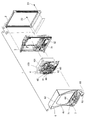
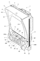
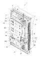
図1は、本発明に係る実施形態の遊技機1を示す斜視図である。図2は、遊技機1の分解斜視図である。図3は、遊技機1の正面図である。図4は、遊技機1の前扉体6を不透明にして示す斜視図である。図5は、図1の遊技機1の背面図である。図6は、遊技機1の斜め後方から見た斜視図である。図7は、遊技機1の右側方から見た断面の概略を示す説明図である。図8は、遊技機1及びこれと接続する機材の回路構成を示すブロック図である。
1 to 8 show an embodiment according to the present invention.
FIG. 1 is a perspective view showing a gaming machine 1 according to an embodiment of the present invention. FIG. 2 is an exploded perspective view of the gaming machine 1. FIG. 3 is a front view of the gaming machine 1. FIG. 4 is a perspective view showing the front door body 6 of the gaming machine 1 in an opaque state. FIG. 5 is a rear view of the gaming machine 1 of FIG. FIG. 6 is a perspective view of the gaming machine 1 as viewed obliquely from the rear. FIG. 7 is an explanatory diagram showing an outline of a cross section viewed from the right side of the gaming machine 1. FIG. 8 is a block diagram showing a circuit configuration of the gaming machine 1 and equipment connected thereto.

初めに遊技機1の全体構成の説明をする。
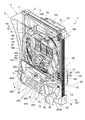
図1において、遊技機1は、固定枠(外枠)2と、遊技盤取付枠(内枠)3と、遊技盤4と、前扉セット5とから構成されている。
First, the overall configuration of the gaming machine 1 will be described.
In FIG. 1, a gaming machine 1 includes a fixed frame (outer frame) 2, a game board mounting frame (inner frame) 3, a game board 4, and a front door set 5.

固定枠2は、ホールにおいて遊技機1を配置される遊技島設備に固定されものであり、機枠又は機体として所定の外郭方形枠サイズに構成されている。   The fixed frame 2 is fixed to the game island facility where the gaming machine 1 is arranged in the hall, and is configured as a machine frame or a predetermined outer rectangular frame size.

遊技盤取付枠3は、枠状に形成され、正面左側上下部に配設された開閉連結支持機構11、12(図3参照)を介して固定枠2に開閉(片持ち横開き)可能に組付けられることで、前記固定枠2に対して開閉可能に支持されている。   The game board mounting frame 3 is formed in a frame shape and can be opened and closed (cantilevered laterally open) to the fixed frame 2 via the open / close connection support mechanisms 11 and 12 (see FIG. 3) disposed on the upper left and right sides of the front. By being assembled, it is supported so as to be openable and closable with respect to the fixed frame 2.

遊技盤取付枠3は、枠形状の内側に遊技盤4が着脱可能にセット保持されている。遊技盤4は、パチンコゲームを展開し得るものである。また、遊技盤取付枠3は、遊技機1の正面右側内部に配設されたシリンダ錠13及びこれと連動する後述の施錠装置161(図10参照)を利用して固定枠2に対して閉鎖状態に保持される。   The game board mounting frame 3 is set and held so that the game board 4 is detachable inside the frame shape. The game board 4 can develop a pachinko game. Further, the game board mounting frame 3 is closed with respect to the fixed frame 2 using a cylinder lock 13 disposed inside the front right side of the gaming machine 1 and a locking device 161 (see FIG. 10) which will be described later. Kept in a state.

遊技盤取付枠3の正面側には、遊技盤取付枠3の前側面域に合わせた方形状の前扉セット5が横開き開閉及び着脱が可能に組付けられており、シリンダ錠13及びこれと連動する後述の施錠装置161(図10参照)を利用して遊技盤取付枠3の前面を覆う閉止状態で保持される。   On the front side of the game board mounting frame 3, a rectangular front door set 5 adapted to the front side area of the game board mounting frame 3 is assembled so that it can be opened, closed, and detached. It is held in a closed state that covers the front surface of the game board mounting frame 3 by using a locking device 161 (see FIG. 10), which will be described later.

図2において、固定枠2は、固定枠本体21の下部に装飾部材22がネジ止めにより取り付け固定される構造になっている。
前扉セット5は、前扉体6及び受皿ユニット7から構成されている。
図1及び図2において、前扉体6は、前記遊技盤取付枠3の前面に開閉可能な状態で支持され、前扉体6には、前記遊技盤取付枠3に取り付けられた遊技盤4を視認可能にする透明性の遊技盤視認用透明窓61(図4参照)が設けられるとともに、透明性を有する透明収納部62(図4参照)が前記遊技盤視認用透明窓61の上側に形成され、当該透明収納部62には、遊技盤4側の立体形状の装飾部材101が挿脱可能な状態で収納されるようになっている。当該透明収納部62は、装飾部材101を外部から視認可能にする。前記遊技盤視認用透明窓61及び前記透明収納部62は、ポリカーボネート等の透明の素材により一体成形されている。
In FIG. 2, the fixed frame 2 has a structure in which a decorative member 22 is attached and fixed to the lower portion of the fixed frame main body 21 with screws.
The front door set 5 includes a front door body 6 and a tray unit 7.
1 and 2, the front door body 6 is supported on the front surface of the game board mounting frame 3 in an openable / closable state, and the front door body 6 has a game board 4 attached to the game board mounting frame 3. A transparent gaming board viewing transparent window 61 (see FIG. 4) is provided, and a transparent storage portion 62 (see FIG. 4) having transparency is provided above the gaming board viewing transparent window 61. The three-dimensional decorative member 101 on the game board 4 side is stored in the transparent storage portion 62 in a state where it can be inserted and removed. The transparent storage portion 62 makes the decorative member 101 visible from the outside. The game board viewing transparent window 61 and the transparent storage portion 62 are integrally formed of a transparent material such as polycarbonate.

受皿ユニット7は、樹脂製のケース本体70を基本構造とし、前記前扉体6の前記遊技盤視認用透明窓61より下側に設けられている。受皿ユニット7には、上側が開放した凹形状の前記遊技球供給皿71が形成されている。前記遊技球供給皿71は、前扉体6の球払出口64から払い出された遊技球を貯留して整列させる。   The tray unit 7 has a resin case main body 70 as a basic structure, and is provided below the game board viewing transparent window 61 of the front door body 6. The tray unit 7 is formed with the concave game ball supply tray 71 having an open upper side. The game ball supply tray 71 stores and aligns the game balls paid out from the ball payout outlet 64 of the front door body 6.

図7において、遊技盤取付枠3に取り付けられた遊技盤4は、基材となる遊技板40の前面に設けられた遊技領域41を前記前扉体6の正面に臨ませている。   In FIG. 7, the game board 4 attached to the game board mounting frame 3 faces the game area 41 provided on the front surface of the game board 40 serving as a base material in front of the front door body 6.

図1において、受皿ユニット7の右下方位置には、遊技盤取付枠3に設けられた発射部31(図2参照)を作動させる操作ハンドル65が配置されている。
操作ハンドル65は前扉体6から遊技者側へ突出し、前記発射部31(図2参照)の駆動によって遊技球を発射させる際に遊技者によって操作されている。
In FIG. 1, an operation handle 65 for operating the launching portion 31 (see FIG. 2) provided on the game board mounting frame 3 is disposed at the lower right position of the tray unit 7.
The operation handle 65 protrudes from the front door body 6 to the player side, and is operated by the player when the game ball is fired by driving the launcher 31 (see FIG. 2).

操作ハンドル65は前記発射部31(図2参照)を駆動させて遊技球を発射させる発射指示部材66を備えている。発射指示部材66は、操作ハンドル65の外周部に、遊技者から見て右回りに回転可能に設けられ、この回転に連動する発射ボリューム65a(図8参照)を有し、遊技者によって直接操作されているときに発射ボリューム65aの抵抗値によって発射部31(図2参照)に遊技球発射の指示を与える。また、操作ハンドル65には遊技者が発射指示部材66を直接操作していることを検出するタッチセンサ65b(図8参照)等が内蔵されている。操作ハンドル65に接触すると、操作ハンドル65に設けられているタッチセンサ65bが、操作ハンドル65に遊技者が触れたことを検知し、発射制御基板36(図6及び図8参照)にタッチ信号を送信する。発射制御基板36は、タッチセンサ65bからタッチ信号を受信すると、発射部31の発射用ソレノイド31a(図8参照)の通電を許可する。   The operation handle 65 includes a firing instruction member 66 that drives the launching portion 31 (see FIG. 2) to launch a game ball. The firing instructing member 66 is provided on the outer peripheral portion of the operation handle 65 so as to be able to rotate clockwise when viewed from the player, and has a firing volume 65a (see FIG. 8) interlocked with this rotation, and is directly operated by the player. When instructed, a game ball launch instruction is given to the launching portion 31 (see FIG. 2) by the resistance value of the launch volume 65a. The operation handle 65 incorporates a touch sensor 65b (see FIG. 8) that detects that the player directly operates the firing instruction member 66. When touching the operation handle 65, a touch sensor 65b provided on the operation handle 65 detects that the player has touched the operation handle 65, and sends a touch signal to the firing control board 36 (see FIGS. 6 and 8). Send. When receiving the touch signal from the touch sensor 65b, the firing control board 36 permits energization of the firing solenoid 31a (see FIG. 8) of the launching unit 31.

発射部31の駆動によって発射された遊技球は、遊技盤4の遊技板40に取り付けられた外側及び内側のレール42、43間を上昇して遊技盤4の上部位置に達した後、遊技領域41内を落下する。遊技領域41には、遊技球を不特定の方向に向けて落下させるための複数の釘に加え、遊技球の落下方向を変化させる風車や入球口が配置されている。   The game ball fired by driving the launching unit 31 rises between the outer and inner rails 42 and 43 attached to the game board 40 of the game board 4 and reaches the upper position of the game board 4, and then the game area 41 falls inside. In the game area 41, in addition to a plurality of nails for dropping the game ball in an unspecified direction, a windmill and a entrance for changing the fall direction of the game ball are arranged.

遊技領域41の中央部分にはセンター役物44が配置されている。センター役物44には、例えば液晶表示器(LCD)を用いた画像出力装置45が配置されている。   A center accessory 44 is disposed in the central portion of the game area 41. For example, an image output device 45 using a liquid crystal display (LCD) is disposed in the center accessory 44.

画像出力装置45の下方には遊技球を受入れ可能な第1始動口46が配置され、第1始動口46の下方には一対の可動片47L、47R(図3参照)を有する第2始動口48が配置されている。第2始動口48は一対の可動片47L、47R(図3参照)が閉状態のときに遊技球の受入れを困難にし、開状態のときに第1始動口46よりも遊技球の受入れを容易にする。   A first start port 46 capable of receiving a game ball is disposed below the image output device 45, and a second start port having a pair of movable pieces 47L and 47R (see FIG. 3) below the first start port 46. 48 is arranged. The second starting port 48 makes it difficult to receive game balls when the pair of movable pieces 47L and 47R (see FIG. 3) are closed, and easier to receive game balls than the first starting port 46 when opened. To.

画像出力装置45の左側には、遊技球の通過を検出し、第2始動口48を一定時間だけ開放させる普通図柄の抽選を行うための入賞ゲート49が配置されている。入賞ゲート49の下方位置等には、遊技球が入球したときに所定数(例えば10個)の賞球払い出しの権利を獲得する普通入賞口50a、50b、50c、50dが配置されている。遊技領域41の最下部にはどの入球口にも入球しなかった遊技球を回収する回収口51が配置されている。   On the left side of the image output device 45, there is arranged a winning gate 49 for detecting the passing of a game ball and performing a lottery of a normal symbol for opening the second starting port 48 for a predetermined time. Below the winning gate 49, etc., there are arranged normal winning ports 50a, 50b, 50c, 50d for acquiring a predetermined number (for example, ten) of paying out award when a game ball enters. At the bottom of the game area 41, a collection port 51 for collecting game balls that have not entered any of the entrances is disposed.

図3において、遊技板40の右下には、主制御基板401(図8参照)に設けられた第1特別図柄抽選手段による抽選結果を表示する第1特別図柄表示装置52、及び主制御基板401(図8参照)に設けられた第2特別図柄抽選手段による抽選結果を表示する第2特別図柄表示装置53が配置されている。これら両表示装置52、53には特別図柄が変動表示されていると共に、所定時間経過後に所定の図柄が停止表示され、始動口への遊技球の入球を契機とする抽選の結果が表示されている。両表示装置52、53には複数のLEDが使用され、特別図柄の変動表示の開始に伴ってLEDが点滅することで、現在抽選中であるかのような印象を遊技者に与える。所定時間経過後には、抽選結果に応じて予め設定されたLEDが点灯表示し、遊技者に抽選結果が報知されている。   3, in the lower right of the game board 40, a first special symbol display device 52 for displaying a lottery result by a first special symbol lottery means provided on the main control board 401 (see FIG. 8), and a main control board A second special symbol display device 53 for displaying a lottery result by the second special symbol lottery means provided in 401 (see FIG. 8) is arranged. These display devices 52 and 53 display a special symbol in a variable manner, and a predetermined symbol is stopped and displayed after a lapse of a predetermined time, and a result of a lottery triggered by a game ball entering the starting port is displayed. ing. A plurality of LEDs are used for both display devices 52 and 53, and the LED blinks with the start of the variable symbol display, giving the player the impression that the lottery is currently being drawn. After a predetermined time has elapsed, an LED preset according to the lottery result is lit up and the lottery result is notified to the player.

特別図柄の変動表示中に第1始動口46、あるいは第2始動口48に遊技球が入球すると、当該入球によって得られる特別図柄の変動表示の権利(以下「保留球」という)が留保されている。この留保された保留球の数は第1特別図柄保留表示装置54(図3参照)及び第2特別図柄保留表示装置55に表示されている。   If a game ball enters the first start port 46 or the second start port 48 during the special symbol variation display, the right to display the special symbol variation display (hereinafter referred to as “reserved ball”) reserved by the entry is reserved. Has been. The number of reserved balls reserved is displayed on the first special symbol hold display device 54 (see FIG. 3) and the second special symbol hold display device 55.

特別図柄の変動表示中に入賞ゲート49に遊技球が入球すると、普通図柄抽選手段による抽選が行われるが、この抽選結果を表示する普通図柄表示装置56が前記両表示装置52、53の付近に配置されている。普通図柄の変動表示中に入賞ゲート49に遊技球が入球することによって得られる普通図柄の変動表示の権利、すなわち保留球の数が普通図柄表示装置57に表示されている。   When a game ball enters the winning gate 49 during the special symbol variation display, the normal symbol lottery means that a lottery is performed. The normal symbol display device 56 for displaying the lottery result is in the vicinity of the display devices 52 and 53. Is arranged. The normal symbol change display right obtained by the game ball entering the winning gate 49 during the normal symbol change display, that is, the number of reserved balls is displayed on the normal symbol display device 57.

画像出力装置45は第1始動口46、または第2始動口48に遊技球が入球したときに複数の装飾図柄の変動表示を開始し、所定時間経過後に当該装飾図柄の変動を停止させる。停止時に特定図柄(例えば「777」)が揃えば、大当たり遊技(長当たり遊技)を実行する権利を獲得したこととなり、その後、大当たり遊技(長当たり遊技)が開始される。大当たり遊技(長当たり遊技)が開始されると、遊技領域41の下方に位置する大入賞口ユニット58における開閉扉59が一定時間、開放する動作を所定回数(例えば15回)繰り返し、入球した遊技球に対応する賞球が払い出されている。   When the game ball enters the first start port 46 or the second start port 48, the image output device 45 starts to display a plurality of decorative symbol variations, and stops the variation of the ornament symbols after a predetermined time. If a specific symbol (for example, “777”) is prepared at the time of stoppage, it means that the right to execute the jackpot game (long win game) is acquired, and then the jackpot game (long hit game) is started. When the big hit game (long win game) is started, the opening / closing door 59 in the big prize opening unit 58 located below the game area 41 is repeatedly opened for a predetermined time (for example, 15 times) to enter the ball. Prize balls corresponding to game balls are paid out.

大入賞口ユニット58は遊技盤4に設けられた大入賞口60を開閉する開閉扉59を開閉自在に支持し、開閉扉59が大入賞口60の前面(表面)側に位置した状態で、遊技盤4の背面に設置されている。開閉扉59は通常時には閉鎖して大入賞口60を閉塞しており、大入賞口60に遊技球が入球することを阻止している。大当たり遊技が開始されたときには、大入賞口開閉ソレノイド58b(図8参照)への通電により開閉扉59が開放して大入賞口60を開放させる。大入賞口60の開放時には、開閉扉59が遊技球を大入賞口60内に導くための受け皿として機能するため、大入賞口60に遊技球が入球可能となる。   The big prize opening unit 58 supports the open / close door 59 that opens and closes the big prize opening 60 provided on the game board 4 so as to freely open and close, and the open / close door 59 is positioned on the front (front surface) side of the big prize opening 60. It is installed on the back of the game board 4. The open / close door 59 is normally closed to close the special winning opening 60, thereby preventing a game ball from entering the special winning opening 60. When the big win game is started, the open / close door 59 is opened by the energization of the big winning opening / closing solenoid 58b (see FIG. 8), and the big winning opening 60 is opened. When the grand prize opening 60 is opened, the open / close door 59 functions as a tray for guiding the game ball into the big prize opening 60, so that the game ball can enter the big prize opening 60.

センター役物44における画像出力装置45の上側及び側方(図1においては紙面右側)には、演出用の役物装置(以下、「演出用役物装置」という)91、92が配置されている。演出用役物装置91、92は例えばモータによって駆動されるようになっている。センター役物44における演出用役物装置91の上側には、遊技機1の商品名を模った電飾装置93が設けられている。   On the upper side and side (right side of the drawing in FIG. 1) of the image output device 45 in the center accessory 44, effect accessory devices (hereinafter referred to as “effect accessory devices”) 91 and 92 are arranged. Yes. The effect accessory devices 91 and 92 are driven by a motor, for example. An electrical decoration device 93 simulating the product name of the gaming machine 1 is provided above the effect accessory device 91 in the center accessory 44.

遊技板40の遊技領域41の上側には、板面を上方に延出させて延出部100が形成されている。延出部100の前面には、装飾部材101が取り付けられている。装飾部材101は、前扉体6が閉塞された状態で透明収納部62に収納され、外部から視認可能である。装飾部材101には、発光ダイオードによる光源が設けられており、演出内容に応じて発光するようになっている。
図1において、受皿ユニット7の前記遊技球供給皿71の前側には、斜め前方に傾斜する傾斜面部72が設けられている。傾斜面部72には、チャンスボタン73が配置されている。チャンスボタン73は、前後の半分程度が前記遊技球供給皿71側に突出して配置している。チャンスボタン73の操作は例えば遊技中における特定のリーチ演出に際し、チャンスボタン73の操作を促すガイダンスが表示されている間有効となる。傾斜面部72の右側には、遊技球貸出装置20(図3参照)に関わる変換ボタンとしての球貸しボタン74と、返却ボタン75が左右に並べて設けられている。前記遊技球供給皿71の後側の内壁の右側には、複数のLEDの点灯によって情報の表示を行う表示部76が設けられている。
On the upper side of the game area 41 of the game board 40, an extension part 100 is formed by extending the board surface upward. A decorative member 101 is attached to the front surface of the extending portion 100. The decorative member 101 is stored in the transparent storage portion 62 in a state where the front door body 6 is closed, and is visible from the outside. The decoration member 101 is provided with a light source by a light emitting diode, and emits light according to the contents of the production.
In FIG. 1, an inclined surface portion 72 that is inclined obliquely forward is provided on the front side of the game ball supply tray 71 of the tray unit 7. A chance button 73 is arranged on the inclined surface portion 72. The chance button 73 is arranged so that about half of the front and rear protrudes toward the game ball supply tray 71. The operation of the chance button 73 is effective while guidance for prompting the operation of the chance button 73 is displayed, for example, in the case of a specific reach effect during the game. On the right side of the inclined surface portion 72, a ball lending button 74 as a conversion button related to the game ball lending device 20 (see FIG. 3) and a return button 75 are provided side by side. On the right side of the inner wall on the rear side of the game ball supply tray 71, a display unit 76 that displays information by lighting a plurality of LEDs is provided.

遊技機1は、図3に示す遊技球貸出装置(CR機)20が送受信可能に接続されるようになっている。遊技球貸出装置20は、プリペイドカード等の記録媒体のカード挿排口500を備え当該記録媒体に記録された金額の残高に応じて貸球の制御を行う。図1に示す表示部76は、前記記録媒体に記録された金額の残高の情報を表示するとともに前記球貸しボタン74と、返却ボタン75が有効中であるか否かを表示する。   The gaming machine 1 is connected to a gaming ball lending device (CR machine) 20 shown in FIG. The game ball lending device 20 includes a card insertion / extraction port 500 for a recording medium such as a prepaid card, and controls lending according to the balance of the amount recorded on the recording medium. The display unit 76 shown in FIG. 1 displays information on the balance of the amount recorded on the recording medium and displays whether the ball lending button 74 and the return button 75 are active.

図1において、表示部76の左斜め後側には、整列路78が設けられている。整列路78は、遊技球供給口79に向けて下方にわずかに傾斜しており、前記遊技球供給皿71からの遊技球を整列させて遊技球供給口79に導く。   In FIG. 1, an alignment path 78 is provided on the diagonally left rear side of the display unit 76. The alignment path 78 is slightly inclined downward toward the game ball supply port 79, and the game balls from the game ball supply tray 71 are aligned and guided to the game ball supply port 79.

整列路78の右側には、球抜きボタン80が設けられており、球抜きボタン80を手動で押し続けることにより、整列路78の先端に設けた開閉板を移動させて球皿側球排出口201を開放し、上球受皿に貯留された遊技球を球抜きして下側球排出口202に送るようにしている。下側球排出口202から排出される遊技球は、通常、ドル箱と呼ばれる遊技球収納箱に受け止められ収納される。   A ball removal button 80 is provided on the right side of the alignment path 78. By continuously pressing the ball removal button 80, the opening / closing plate provided at the end of the alignment path 78 is moved to move the ball tray side ball discharge port. 201 is opened, and the game balls stored in the upper ball tray are removed and sent to the lower ball discharge port 202. The game balls discharged from the lower ball discharge port 202 are normally received and stored in a game ball storage box called a dollar box.

遊技盤取付枠3には、演出効果音、または不正を知らしめる音声を出力するスピーカ32(図2参照)が組み込まれている。   The game board mounting frame 3 incorporates a speaker 32 (see FIG. 2) that outputs a production effect sound or a sound that informs fraud.

受皿ユニット7の前面の左右には、遊技盤取付枠3に設けられたスピーカ32(図2参照)からの音声の放出を行う放音部203L、203Rが設けられている。   On the left and right sides of the front surface of the tray unit 7, sound emitting units 203 </ b> L and 203 </ b> R that emit sound from a speaker 32 (see FIG. 2) provided on the game board mounting frame 3 are provided.

図2に示すスピーカ32は高音・中音・低音の領域を出力できる機能を有し、通常演出時は高音・中音・低音をバランス良く出力するが、後述する特別演出時、または不正等があった場合には周りに良く聞こえるように高音領域を高く出力するように制御されている。   The speaker 32 shown in FIG. 2 has a function capable of outputting high, medium, and low sound areas, and outputs high sound, medium sound, and low sound in a balanced manner during normal performance. If there is, it is controlled to output a high sound region high so that it can be heard well around.

放音部203L、203Rの間には、透明部204が設けられ、透明部204の内側には演出用の発光を行う電飾装置205が設けられている。   A transparent portion 204 is provided between the sound emitting portions 203 </ b> L and 203 </ b> R, and an electrical decoration device 205 that performs light emission for production is provided inside the transparent portion 204.

図4において、前扉体6の遊技盤視認用透明窓61は、板面が前方に向いた平面形状に形成されている。透明収納部62は、横長に形成され、板面が前側斜め下方に向いた平面形状の中間部211の左右に、傾斜面部212、213が設けられている。傾斜面部212、213は、右斜め下側前方及び左斜め下側前方を向いている。   In FIG. 4, the game board visualizing transparent window 61 of the front door body 6 is formed in a planar shape with the plate surface facing forward. The transparent storage portion 62 is formed in a horizontally long shape, and inclined surface portions 212 and 213 are provided on the left and right of the planar intermediate portion 211 whose plate surface faces obliquely downward on the front side. The inclined surface portions 212 and 213 face the right diagonally lower front and the left diagonally lower front.

以下、図5及び図6を用いて遊技機1の背面側について説明する。
図5及び図6において、遊技機1の裏面の上部には、遊技球を貯留する貯留タンク33が設置されており、貯留タンク33は、遊技機1の裏面の左側の上部賞球ケース34に覆われた払出装置35に接続されている。賞球ケース34は、遊技球通路を介して入球に基づく賞球(景品)としての遊技球や球貸し要求に基づく遊技球を遊技者に払い出す。払出装置35は、例えばステッピングモータ等の駆動部31b(図8参照)が駆動することによって、賞球または貸し球としての遊技球を1個ずつ遊技者に払い出す。
Hereinafter, the back side of the gaming machine 1 will be described with reference to FIGS. 5 and 6.
5 and 6, a storage tank 33 for storing game balls is installed at the upper part of the back surface of the gaming machine 1, and the storage tank 33 is attached to the upper prize ball case 34 on the left side of the back surface of the game machine 1. It is connected to the covered dispensing device 35. The prize ball case 34 pays out to the player a game ball as a prize ball (prize) based on entry or a game ball based on a ball rental request through the game ball passage. The payout device 35 pays out a game ball as a winning ball or a rental ball to the player one by one when the driving unit 31b (see FIG. 8) such as a stepping motor is driven.

遊技機1の裏面の払出装置35の下側には、発射制御基板36及び払出制御基板37が前後に並べた状態で取り付けられている。発射制御基板36及び払出制御基板37は、基板ケース301により収納されている。   A launch control board 36 and a payout control board 37 are attached to the lower side of the backside of the gaming machine 1 below the payout device 35 in a state where they are arranged in the front-rear direction. The launch control board 36 and the payout control board 37 are housed in a board case 301.

遊技機1の裏面の払出制御基板37の右側には、基板ケース302に収納された電源基板38が取り付けられている。遊技機1の裏面の払出制御基板37の上側には、払出情報出力端子板39が設けられている。払出情報出力端子板39は、基板ケース301により収納されている。   A power supply board 38 housed in a board case 302 is attached to the right side of the payout control board 37 on the back surface of the gaming machine 1. A payout information output terminal board 39 is provided above the payout control board 37 on the back surface of the gaming machine 1. The payout information output terminal board 39 is accommodated in the board case 301.

貯留タンク33、賞球ケース34、払出装置35、発射制御基板36、払出制御基板37及び電源基板38は、遊技盤取付枠3側に固定されている。   The storage tank 33, prize ball case 34, payout device 35, launch control board 36, payout control board 37, and power supply board 38 are fixed to the game board mounting frame 3 side.

遊技機1の裏側の電源基板38の上側には、基板ケース411に収納され主制御基板401が設けられる。遊技機1の裏側の主制御基板401と貯留タンク33の間には、基板ケース413に収納され背面カバー412で覆われた演出制御基板402が設けられている。遊技機1の裏側の演出制御基板402の左側下方には、遊技情報出力端子板403が取り付けられている。   A main control board 401 housed in a board case 411 is provided above the power supply board 38 on the back side of the gaming machine 1. Between the main control board 401 and the storage tank 33 on the back side of the gaming machine 1, an effect control board 402 that is housed in the board case 413 and covered with the back cover 412 is provided. A game information output terminal board 403 is attached to the lower left side of the effect control board 402 on the back side of the gaming machine 1.

主制御基板401、演出制御基板402、遊技情報出力端子板403、基板ケース411、413及び背面カバー412は、遊技盤4側に取り付けられている。   The main control board 401, the effect control board 402, the game information output terminal board 403, the board cases 411 and 413, and the back cover 412 are attached to the game board 4 side.

(制御手段の内部構成)
次に、図8を用いて遊技の進行を制御する制御手段について説明する。
図8において、遊技機1の制御手段は、主制御基板401、演出制御基板402、払出制御基板37、ランプ制御基板404及び画像制御基板405から構成されている。
(Internal structure of control means)
Next, control means for controlling the progress of the game will be described with reference to FIG.
In FIG. 8, the control means of the gaming machine 1 includes a main control board 401, an effect control board 402, a payout control board 37, a lamp control board 404 and an image control board 405.

主制御基板401は遊技の基本動作を制御する。この主制御基板401は、メインCPU401a、メインROM401b、メインRAM401cを備えている。メインCPU401aは、各検出センサやタイマからの入力信号に基づいて、メインROM401bに格納されたプログラムを読み出して演算処理を行うとともに、各装置や表示装置を直接制御したり、あるいは演算処理の結果に応じて他の基板に所定のコマンドを送信したりする。メインRAM401cは、メインCPU401aの演算処理時におけるデータのワークエリアとして機能する。   The main control board 401 controls the basic operation of the game. The main control board 401 includes a main CPU 401a, a main ROM 401b, and a main RAM 401c. The main CPU 401a reads out the program stored in the main ROM 401b based on the input signals from each detection sensor and timer, performs arithmetic processing, and directly controls each device and display device, or determines the result of the arithmetic processing. In response, a predetermined command is transmitted to another board. The main RAM 401c functions as a data work area during the arithmetic processing of the main CPU 401a.

前記主制御基板401の入力側には、第1始動口検出センサ46a、第2始動口検出センサ48a、第1大入賞口検出センサ58a、入賞ゲート検出センサ49a及び一般入賞口検出センサ50eが接続されている。これら各センサ46a、48a、58a、49a、50eは、それぞれ対応する検出信号を主制御基板401に送信する。   Connected to the input side of the main control board 401 are a first start port detection sensor 46a, a second start port detection sensor 48a, a first large winning port detection sensor 58a, a winning gate detection sensor 49a, and a general winning port detection sensor 50e. Has been. Each of these sensors 46a, 48a, 58a, 49a, 50e transmits a corresponding detection signal to the main control board 401.

主制御基板401の出力側には、第2始動口48の一対の可動片47L、47Rを動かす第2始動口開閉ソレノイド48b、大入賞口ユニット58の大入賞口開閉扉59を動かす大入賞口開閉ソレノイド58bが接続されている。主制御基板401は、出力ポート(図示せず)を介して各ソレノイド48b、58bを制御する信号を各ソレノイド48b、58bに送信する。また、主制御基板401の出力側には、第1特別図柄表示装置52、第2特別図柄表示装置53及び普通図柄表示装置56が接続されるとともに、第1特別図柄保留表示装置54、第2特別図柄保留表示装置55及び普通図柄保留表示装置57が接続されている。主制御基板401は、出力ポート(図示せず)を介して各表示装置52、53、54、55、56、57を制御する信号を各表示装置52、53、54、55、56、57に送信する。また、主制御基板401は、第1始動口検出センサ46a、第2始動口検出センサ48a、一般入賞口検出センサ50e及び第1大入賞口検出センサ58aの検出結果に基づき、各入球口(第1始動口46、第2始動口48、普通入賞口50a、50b、50c、50d、大入賞口60)に入球した遊技球に対応した賞球数を払い出させる賞球要求信号を払出制御基板37に送信する。   On the output side of the main control board 401, a second start opening / closing solenoid 48b for moving the pair of movable pieces 47L, 47R of the second start opening 48, and a large winning opening for moving the large winning opening / closing door 59 of the large winning opening unit 58 are provided. An open / close solenoid 58b is connected. The main control board 401 transmits a signal for controlling each solenoid 48b, 58b to each solenoid 48b, 58b via an output port (not shown). Further, the first special symbol display device 52, the second special symbol display device 53, and the normal symbol display device 56 are connected to the output side of the main control board 401, and the first special symbol display device 54, the second special symbol display device 54, and the second special symbol display device 54. A special symbol hold display device 55 and a normal symbol hold display device 57 are connected. The main control board 401 sends a signal for controlling each display device 52, 53, 54, 55, 56, 57 to each display device 52, 53, 54, 55, 56, 57 via an output port (not shown). Send. In addition, the main control board 401 determines each entrance (on the basis of the detection results of the first start opening detection sensor 46a, the second start opening detection sensor 48a, the general winning opening detection sensor 50e, and the first big winning opening detection sensor 58a). 1st start opening 46, 2nd start opening 48, normal winning opening 50a, 50b, 50c, 50d, big winning opening 60) paying out the winning ball request signal which pays out the number of winning balls corresponding to the game ball which entered Transmit to the control board 37.

さらに、主制御基板401の出力側には遊技情報出力端子板403が接続されている。主制御基板401は、出力ポートを介して、所定の遊技に関する情報(以下、遊技情報という)が変換された外部信号を遊技情報出力端子板403に送信する。遊技情報出力端子板403には遊技機1の外側に設けられた遊技情報表示装置10及び遊技店のホールコンピュータが接続されており、遊技情報出力端子板403からは前記の所定の遊技情報(外部信号)が遊技情報表示装置10及びホールコンピュータに送信される。遊技者には、所定の遊技情報が遊技情報表示装置10で出力(表示)されることで、遊技機(台)選びの判断材料が提供されることになる。一方、遊技店は、前記所定の遊技情報がホールコンピュータに接続された表示装置やプリンターで出力(表示・印刷)されることで、各遊技機の稼働状況を把握することができる。   Further, a game information output terminal board 403 is connected to the output side of the main control board 401. The main control board 401 transmits an external signal obtained by converting information related to a predetermined game (hereinafter referred to as game information) to the game information output terminal board 403 via the output port. The game information output terminal board 403 is connected to the game information display device 10 provided outside the gaming machine 1 and the hall computer of the game store. The game information output terminal board 403 is connected to the predetermined game information (external Signal) is transmitted to the game information display device 10 and the hall computer. A predetermined game information is output (displayed) by the game information display device 10 to the player, thereby providing a judgment material for selecting a gaming machine (unit). On the other hand, the game store can grasp the operating status of each gaming machine by outputting (displaying / printing) the predetermined game information with a display device or printer connected to the hall computer.

演出制御基板402は、主に遊技中や待機中等の各演出を制御する。この演出制御基板402は、サブCPU402a、サブROM402b、サブRAM402cを備えており、主制御基板401に、当該主制御基板401から演出制御基板402への一方向に通信可能に接続されている。また、演出制御基板402の入力側には、チャンスボタン検出スイッチ73aが接続されている。演出制御基板402には、チャンスボタン73の操作が行われたことを示す演出ボタン検出信号がチャンスボタン検出スイッチ73aから送信される。   The effect control board 402 mainly controls each effect such as during a game or standby. The effect control board 402 includes a sub CPU 402a, a sub ROM 402b, and a sub RAM 402c, and is connected to the main control board 401 so as to be communicable in one direction from the main control board 401 to the effect control board 402. A chance button detection switch 73 a is connected to the input side of the effect control board 402. An effect button detection signal indicating that the operation of the chance button 73 has been performed is transmitted from the chance button detection switch 73a to the effect control board 402.

サブCPU402aは、主制御基板401から送信されたコマンド、または、前記チャンスボタン検出スイッチ73aや図示しないタイマからの受信信号に基づいて、サブROM402bに格納されたプログラムを読み出して演算処理を行うとともに、当該処理に基づいて、コマンドをランプ制御基板404や画像制御基板405に送信する。サブRAM402cは、サブCPU402aの演算処理時におけるデータのワークエリアとして機能する。   The sub CPU 402a reads out a program stored in the sub ROM 402b based on a command transmitted from the main control board 401 or a received signal from the chance button detection switch 73a or a timer (not shown), and performs arithmetic processing. Based on this processing, a command is transmitted to the lamp control board 404 and the image control board 405. The sub RAM 402c functions as a data work area during the arithmetic processing of the sub CPU 402a.

払出制御基板37は、遊技球の発射制御と遊技球の払い出し制御とを行う。この払出制御基板37は、払出CPU37a、払出ROM37b、払出RAM37cを備えており、主制御基板401及び発射制御基板36に対して、双方向に通信可能に接続されている。   The payout control board 37 performs game ball launch control and game ball payout control. The payout control board 37 includes a payout CPU 37a, a payout ROM 37b, and a payout RAM 37c. The payout control board 37 is connected to the main control board 401 and the launch control board 36 so as to be capable of bidirectional communication.

払出CPU37aの入力側には、払出装置35において遊技球が払い出されたか否かを検知する払出球計数スイッチ35aが接続されている。また、払出CPU37aの入力側には、球貸しボタン74の操作を検出する球貸しボタン検出スイッチ74aと、返却ボタン75の操作を検出する返却ボタン検出スイッチ75aとが設けられている。   On the input side of the payout CPU 37a, a payout ball counting switch 35a for detecting whether or not a game ball has been paid out in the payout device 35 is connected. On the input side of the payout CPU 37a, a ball lending button detection switch 74a for detecting the operation of the ball lending button 74 and a return button detection switch 75a for detecting the operation of the return button 75 are provided.

払出CPU37aは、払出球計数スイッチ35aからの払出球検知信号と、球貸しボタン検出スイッチ74aからの球貸しボタン操作検出信号と、返却ボタン検出スイッチ75aからの返却ボタン操作検出信号と、タイマからの受信信号とに基づいて、払出ROM37bに格納されたプログラムを読み出して演算処理を行うとともに、当該処理に基づいて、対応するデータを主制御基板401に送信する。   The payout CPU 37a receives a payout ball detection signal from the payout ball counting switch 35a, a ball lending button operation detection signal from the ball lending button detection switch 74a, a return button operation detection signal from the return button detection switch 75a, and a timer. Based on the received signal, the program stored in the payout ROM 37b is read out to perform arithmetic processing, and corresponding data is transmitted to the main control board 401 based on the processing.

払出制御基板37の出力側には、貯留タンク33から所定数の遊技球を遊技者に払い出すための払出装置35の払出駆動部35bが接続されている。払出CPU37aは、主制御基板401から送信された賞球要求信号に基づいて、払出ROM37bから所定のプログラムを読み出して演算処理を行うとともに、払出装置35を制御して所定の遊技球を遊技者に払い出す。このとき、払出RAM37cは、払出CPU37aの演算処理時におけるデータのワークエリアとして機能する。   On the output side of the payout control board 37, a payout driving unit 35 b of the payout device 35 for paying out a predetermined number of game balls from the storage tank 33 to the player is connected. Based on the prize ball request signal transmitted from the main control board 401, the payout CPU 37a reads a predetermined program from the payout ROM 37b and performs arithmetic processing, and controls the payout device 35 to give a predetermined game ball to the player. Pay out. At this time, the payout RAM 37c functions as a data work area during the calculation process of the payout CPU 37a.

また、払出CPU37aは、遊技機1の外側に設けられた遊技球貸出装置(カードユニット)20が払出制御基板37に接続されているか否かを確認し、遊技球貸出装置20が接続されていれば、発射制御基板36に遊技球を発射させることを許可する発射制御データを送信する。   The payout CPU 37a checks whether or not the game ball lending device (card unit) 20 provided outside the gaming machine 1 is connected to the payout control board 37, and the game ball lending device 20 is connected. For example, the launch control data permitting the launch control board 36 to launch the game ball is transmitted.

払出制御基板37の出力側には、表示部76(図1参照)に設けられた遊技情報表示基板81が接続されている。払出CPU37aは、遊技球貸出装置20から受信したデータに基づいて、遊技球貸出装置20の前記カード挿排口500に挿入されたカードの残高を情報表示基板81に表示すとともに、球貸しボタン74有効中である、即ち、遊技球貸出装置20を用いた玉貸し可能であるか否かを情報表示基板81に表示する。   A game information display board 81 provided in the display unit 76 (see FIG. 1) is connected to the output side of the payout control board 37. Based on the data received from the game ball lending device 20, the payout CPU 37a displays the balance of the card inserted into the card insertion / extraction port 500 of the game ball lending device 20 on the information display board 81, and a ball lend button 74. It is displayed on the information display board 81 whether it is valid, that is, whether or not the ball lending using the game ball lending device 20 is possible.

発射制御基板36は、払出制御基板37から発射制御データを受信すると発射部31(図2参照)による発射の許可を行う。そして、操作ハンドル65(図1参照)に設けられたタッチセンサ65bからのタッチ信号と発射指示部材66(図1参照)に連動する発射ボリューム65aからの入力信号とを読み出し、発射部31(図2参照)の発射用ソレノイド31aを通電制御し、遊技球を発射させる。   When the launch control board 36 receives the launch control data from the payout control board 37, the launch control board 36 permits the launching unit 31 (see FIG. 2) to launch. Then, the touch signal from the touch sensor 65b provided on the operation handle 65 (see FIG. 1) and the input signal from the firing volume 65a linked to the firing instruction member 66 (see FIG. 1) are read out, and the launching unit 31 (see FIG. 1). 2) to control the energization of the launching solenoid 31a to launch a game ball.

実施形態では、発射用ソレノイド31aの回転速度は、発射制御基板36に設けられた水晶発振器の出力周期に基づく周波数から、約99.9(回/分)に設定されている。これにより、1分間における発射遊技数は、発射用ソレノイド31aが1回転する毎に1個発射されるため、約99.9(個/分)となる。   In the embodiment, the rotation speed of the firing solenoid 31a is set to about 99.9 (times / minute) from the frequency based on the output period of the crystal oscillator provided on the firing control board 36. As a result, the number of games played in one minute is about 99.9 (pieces / minute) because one shot is fired each time the firing solenoid 31a rotates once.

ランプ制御基板404は、前記各基板と同様に、ランプCPU404a、ランプROM404b、ランプRAM404cを備えており、遊技盤2に設けられた電飾装置93、205及び装飾部材101の発光ダイオードを点灯制御する。また、演出用役物装置91、92を作動させるソレノイドやモータ等の駆動源を通電制御する。このランプ制御基板404は、演出制御基板402に接続されており、演出制御基板402から送信されたコマンドに基づいて、前記の各制御を行うこととなる。   The lamp control board 404 includes a lamp CPU 404a, a lamp ROM 404b, and a lamp RAM 404c, similarly to the above-described boards, and controls lighting of the lighting devices 93 and 205 provided on the game board 2 and the light emitting diodes of the decoration member 101. . In addition, energization control is performed on a drive source such as a solenoid or a motor that operates the effect accessory devices 91 and 92. The lamp control board 404 is connected to the effect control board 402, and performs each of the above-described controls based on a command transmitted from the effect control board 402.

画像制御基板405は、少なくとも画像出力装置45に表示される動画や静止画等の画像を制御する画像制御部405Bと、スピーカ32から出力される音を制御する音声制御部405Cと、画像制御部405B及び音制御部405Cを統括制御する統括部405Aとを有する。   The image control board 405 includes at least an image control unit 405B that controls images such as moving images and still images displayed on the image output device 45, an audio control unit 405C that controls sound output from the speaker 32, and an image control unit. 405B and a sound control unit 405C.

画像制御基板405の統括部405Aは、演出制御基板402から送信される演出確定コマンドを受信し、統括部405Aの統括CPU405A1が画像出力装置45に表示される画像の制御及びスピーカ32から出力される音の制御を行う。統括ROM405A2には、当該統括CPU405A1の実行する制御プログラムが記憶されている。統括CPU405A1は、統括ROM405A2が接続されるとともに、統括RAM405A3が接続されており、統括CPU405A1の動作に必要な制御プログラムが読み出されるようになっている。   The overall unit 405A of the image control board 405 receives the effect confirmation command transmitted from the effect control board 402, and the overall CPU 405A1 of the overall unit 405A controls the image displayed on the image output device 45 and is output from the speaker 32. Control the sound. The overall ROM 405A2 stores a control program executed by the overall CPU 405A1. The general CPU 405A1 is connected to a general ROM 405A2 and a general RAM 405A3 so that a control program necessary for the operation of the general CPU 405A1 is read out.

また、統括CPU405A1は、画像制御部405Bの画像CPU405B1、及び、音制御部405Cの音CPU405C1に接続される。画像CPU405B1は画像出力装置45に表示させる画像に対応する画像信号を生成し、生成した画像信号を画像出力装置45の駆動回路に送信する。一方、音CPU405C1は、スピーカ32から出力させる音に対応する音信号を生成し、生成した音信号をスピーカ32の駆動回路に送信する。   The overall CPU 405A1 is connected to the image CPU 405B1 of the image control unit 405B and the sound CPU 405C1 of the sound control unit 405C. The image CPU 405B1 generates an image signal corresponding to the image to be displayed on the image output device 45, and transmits the generated image signal to the drive circuit of the image output device 45. On the other hand, the sound CPU 405C1 generates a sound signal corresponding to the sound output from the speaker 32, and transmits the generated sound signal to the drive circuit of the speaker 32.

画像CPU405B1には、画像ROM405B2が接続されている。画像ROM405B2には、画像CPU405B1の実行する制御プログラムが記憶されている。画像ROM405B2からは、画像CPU405B1の動作に必要な制御プログラムが画像CPU405B1の制御により読み出されるようになっている。また、画像CPU405B1は、画像出力装置45に表示する、例えば背景、キャラクタ、装飾図柄等の画像に係る画像データも予め記憶されている。また、画像CPU405B1は、生成した画像信号を展開して記憶させる画像RAM405B3にも接続されている。   An image ROM 405B2 is connected to the image CPU 405B1. The image ROM 405B2 stores a control program executed by the image CPU 405B1. From the image ROM 405B2, a control program necessary for the operation of the image CPU 405B1 is read out under the control of the image CPU 405B1. The image CPU 405B1 also stores in advance image data relating to an image such as a background, a character, a decorative design, and the like displayed on the image output device 45. The image CPU 405B1 is also connected to an image RAM 405B3 that develops and stores the generated image signal.

なお、画像CPU405B1は、画像出力装置45に対して、背景画像表示処理、装飾図柄表示処理、キャラクタ画像表示処理など各種画像処理を実行するが、背景画像、装飾図柄画像、キャラクタ画像は、画像出力装置45の表示画面上において重畳表示される。すなわち、装飾図柄画像やキャラクタ画像は背景画像よりも手前に見えるように表示される。このとき、同一位置に背景画像と図柄画像が重なる場合、Zバッファ法など周知の陰面消去法により各画像データのZバッファのZ値を参照することで、図柄画像を優先して画像RAM405B3に記憶させる。   The image CPU 405B1 executes various image processing such as background image display processing, decorative design display processing, and character image display processing on the image output device 45. However, the background image, decorative design image, and character image are output as images. The image is superimposed on the display screen of the device 45. That is, the decorative design image and the character image are displayed so as to be seen in front of the background image. At this time, if the background image and the design image overlap at the same position, the design image is preferentially stored in the image RAM 405B3 by referring to the Z value of the Z buffer of each image data by a known hidden surface removal method such as the Z buffer method. Let

一方、音CPU405C1にも、音声ROM405C2が接続されている。音声ROM405C2には、音CPU405C1の実行する制御プログラムが記憶されている。音声ROM405C2からは音405C1の動作に必要な制御プログラムが音CPU405C1の制御により読み出されるようになっている。音405C1には、スピーカ32から出力される音の音データも予め記憶されている。また、音CPU405C1は、生成した音信号を展開して記憶する音RAM405C3にも接続されている。   On the other hand, the sound ROM 405C2 is also connected to the sound CPU 405C1. The sound ROM 405C2 stores a control program executed by the sound CPU 405C1. A control program necessary for the operation of the sound 405C1 is read from the sound ROM 405C2 under the control of the sound CPU 405C1. In the sound 405C1, sound data of the sound output from the speaker 32 is also stored in advance. The sound CPU 405C1 is also connected to a sound RAM 405C3 that expands and stores the generated sound signal.

一方、上述の遊技情報出力端子板403は、主制御基板401において生成された外部信号を遊技店のホールコンピュータ及び遊技情報表示装置10に伝達するための中継的な基板である。本実施形態においては、遊技情報出力端子板403は出力側で遊技情報表示装置10にのみ直接接続されており、遊技情報表示装置10を介してホールコンピュータに接続されている。遊技情報出力端子板403は、主制御基板401と配線接続され、遊技店のホールコンピュータ等と接続をするためのコネクタが設けられている。   On the other hand, the game information output terminal board 403 is a relay board for transmitting an external signal generated in the main control board 401 to the hall computer of the game shop and the game information display device 10. In the present embodiment, the game information output terminal board 403 is directly connected only to the game information display device 10 on the output side, and is connected to the hall computer via the game information display device 10. The game information output terminal board 403 is connected to the main control board 401 by wiring, and is provided with a connector for connecting to a hall computer or the like of a game store.

なお、実施形態では遊技情報出力端子板403は遊技情報表示装置10を介してホールコンピュータに接続されているが、遊技情報出力端子板403から遊技情報表示装置10及びホールコンピュータの双方に接続される構成でもよい。また、遊技情報出力端子板403はホールコンピュータを介して遊技情報表示装置10に接続される構成でもよい。   In the embodiment, the game information output terminal plate 403 is connected to the hall computer via the game information display device 10, but is connected to both the game information display device 10 and the hall computer from the game information output terminal plate 403. It may be configured. The game information output terminal board 403 may be connected to the game information display device 10 via a hall computer.

上述の払出情報出力端子板39は、払出制御基板37において生成された、賞球払出個数を示す賞球要求信号及び貸し球払出個数を示す球貸要求信号をホールコンピュータに出力するための中継的な基板である。本実施形態においては、払出情報出力端子板39も遊技情報表示装置10を介してホールコンピュータに接続されている。払出情報出力端子板39は、払出制御基板37と配線接続され、遊技店のホールコンピュータ等と接続をするためのコネクタが設けられている。   The above-mentioned payout information output terminal board 39 is a relay for outputting to the hall computer a prize ball request signal indicating the number of prize balls to be paid and a ball lending request signal indicating the number of balls to be paid out, generated on the payout control board 37. It is a simple substrate. In the present embodiment, the payout information output terminal board 39 is also connected to the hall computer via the game information display device 10. The payout information output terminal board 39 is wired to the payout control board 37 and is provided with a connector for connecting to a hall computer or the like of a game store.

なお、実施形態では払出情報出力端子板39は遊技情報表示装置10を介してホールコンピュータに接続されているが、払出情報出力端子板39から遊技情報表示装置10及びホールコンピュータの双方に接続される構成でもよい。また、払出情報出力端子板39はホールコンピュータを介して遊技情報表示装置10に接続される構成でもよい。   In the embodiment, the payout information output terminal plate 39 is connected to the hall computer via the game information display device 10, but is connected to both the game information display device 10 and the hall computer from the payout information output terminal plate 39. It may be configured. Further, the payout information output terminal board 39 may be connected to the game information display device 10 via a hall computer.

電源基板38は、コンデンサからなるバックアップ電源を備えており(図示せず)、遊技機に供給する電源電圧を監視し、電源電圧が所定値以下となったときに、電断検知信号を主制御基板401に出力する。より具体的には、電断検知信号がハイレベルになるとメインCPU401aは動作可能状態になり、電断検知信号がローレベルになるとメインCPU401aは動作停止状態になる。バックアップ電源はコンデンサに限らず、例えば、電池でもよく、コンデンサと電池とを併用して用いてもよい。   The power supply board 38 has a backup power supply made of a capacitor (not shown), monitors the power supply voltage supplied to the gaming machine, and controls the power interruption detection signal when the power supply voltage falls below a predetermined value. Output to the substrate 401. More specifically, when the power interruption detection signal becomes high level, the main CPU 401a becomes operable, and when the power interruption detection signal becomes low level, the main CPU 401a becomes inactive state. The backup power source is not limited to a capacitor, and for example, a battery may be used, and a capacitor and a battery may be used in combination.

以下、遊技機1の各部材について詳細に説明する。
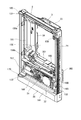
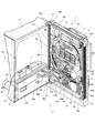
図9乃至図19は本発明に係る実施形態を示し、図9は、固定枠2の分解斜視図である。図10は、遊技盤取付枠3の斜視図である。図11は遊技盤4の斜視図である。図12は、前扉体6の右斜め前方から見た斜視図である。図13は、前扉セット5の右斜め後方から見た斜視図である。図14は、前扉セット5の情報表示器及びその周辺部の分解斜視図である。図15は、前扉セット5の情報表示器及びその周辺部の組み立てた状態の斜視図である。図16は、固定枠2と遊技盤取付枠3を組み立てた状態の斜視図である。図17は、固定枠2と遊技盤取付枠3を組み立て遊技盤取付枠3に遊技盤4を取り付けた状態の斜視図である。図18は、固定枠2から遊技盤取付枠3を開いた状態の遊技機1の斜視図である。図19は、遊技盤取付枠3から前扉セット505を開いた状態の遊技機1の斜視図である。
Hereinafter, each member of the gaming machine 1 will be described in detail.
9 to 19 show an embodiment according to the present invention, and FIG. 9 is an exploded perspective view of the fixed frame 2. FIG. 10 is a perspective view of the game board mounting frame 3. FIG. 11 is a perspective view of the game board 4. FIG. 12 is a perspective view of the front door body 6 as seen from diagonally right front. FIG. 13 is a perspective view of the front door set 5 as viewed from the right rear side. FIG. 14 is an exploded perspective view of the information display of the front door set 5 and its peripheral part. FIG. 15 is a perspective view of the information indicator of the front door set 5 and its peripheral part in an assembled state. FIG. 16 is a perspective view of a state in which the fixed frame 2 and the game board mounting frame 3 are assembled. FIG. 17 is a perspective view of a state in which the fixed frame 2 and the game board mounting frame 3 are assembled and the game board 4 is attached to the game board mounting frame 3. FIG. 18 is a perspective view of the gaming machine 1 in a state where the game board mounting frame 3 is opened from the fixed frame 2. FIG. 19 is a perspective view of the gaming machine 1 in a state where the front door set 505 is opened from the gaming board mounting frame 3.

まず、固定枠2について詳細に説明する。
図9において、実施形態における固定枠2は、固定枠本体21と、装飾部材22と、ネジ23、23とから構成されている。
First, the fixed frame 2 will be described in detail.
In FIG. 9, the fixed frame 2 in the embodiment includes a fixed frame main body 21, a decorative member 22, and screws 23 and 23.

固定枠本体21は、例えば上下辺部111、112がアルミ製の板材121、122と木製の板材123、124が重ねて構成され、左右側辺部113、114がアルミ製の板材125、126により構成され、これら各板材が小ネジ等の離脱可能な締結具により全体として矩形枠状に組み付けられている。   The fixed frame main body 21 has, for example, upper and lower sides 111 and 112 formed by overlapping aluminum plate members 121 and 122 and wooden plate members 123 and 124, and left and right side portions 113 and 114 are made of aluminum plate members 125 and 126. These plate members are assembled in a rectangular frame shape as a whole by a detachable fastener such as a small screw.

左側辺部113の上下端部には、図2に示した開閉連結支持機構11、12の上軸受片131及び下軸受片132がそれぞれ設けられている。当該上軸受片131及び下軸受片132にて、図16に示すように、遊技盤取付枠3の上下部が回動可能に支持されており、これにより遊技盤取付枠3が開閉可能となる。   At the upper and lower ends of the left side portion 113, the upper and lower connecting pieces 131 and 132 shown in FIG. 2 are provided. As shown in FIG. 16, the upper and lower bearing pieces 131 and 132 support the upper and lower portions of the game board mounting frame 3 so that the game board mounting frame 3 can be opened and closed. .

図9において、右側辺部114の枠内側面の上部及び下部には、遊技盤取付枠3に設けられた後述する施錠装置161(図10参照)の内枠鉤部163、164(図10参照)に対応して、上下一対の鉤受部133、134が設けられている。これにより、固定枠2に対して遊技盤取付枠3が閉じられた状態で、内枠鉤部163、164は、当該鉤受部133、134に係止される。   9, on the upper and lower parts of the inner side surface of the right side 114, inner frame collars 163 and 164 (see FIG. 10) of a locking device 161 (see FIG. 10), which will be described later, provided on the game board mounting frame 3. ) Is provided with a pair of upper and lower hook receiving portions 133 and 134. As a result, the inner frame flange parts 163 and 164 are locked to the hook receiving parts 133 and 134 in a state where the game board mounting frame 3 is closed with respect to the fixed frame 2.

さらに、固定枠2の下辺部112には、樹脂製の装飾部材22がネジ23、23によりネジ止め固定されている。装飾部材22の前面上側には、前方を向く垂直面部141が設けられている。装飾部材22の前面下側には、前側斜め下方を向く傾斜面部142が設けられている。   Further, a resin decorative member 22 is fixed to the lower side portion 112 of the fixed frame 2 with screws 23 and 23. A vertical surface portion 141 facing forward is provided on the upper side of the front surface of the decorative member 22. On the lower side of the front surface of the decorative member 22, an inclined surface portion 142 is provided that faces the front obliquely downward.

次に、遊技盤取付枠3を詳細に示す。
図10において、遊技盤取付枠3は、外形が矩形状をなす樹脂ベース151を主体に構成されており、当該樹脂ベース151の中央部には略四角形状の部品挿入孔152が形成されている。
Next, the game board mounting frame 3 is shown in detail.
In FIG. 10, the game board mounting frame 3 is mainly configured by a resin base 151 whose outer shape is a rectangular shape, and a substantially rectangular component insertion hole 152 is formed at the center of the resin base 151. .

部品挿入孔152には、図6に示した遊技盤4の主制御基板401、演出制御基板402、遊技情報出力端子板403、基板ケース411、413及び背面カバー412が挿入される。   The main control board 401, the effect control board 402, the game information output terminal board 403, the board cases 411 and 413, and the back cover 412 of the game board 4 shown in FIG.

図10において、当該樹脂ベース151の部品挿入孔152の前側には、遊技盤4の遊技板40が内側に挿入される枠状部153が形成されている。   In FIG. 10, a frame-like portion 153 into which the game board 40 of the game board 4 is inserted is formed on the front side of the component insertion hole 152 of the resin base 151.

枠状部153は、上壁154、下壁155、左側壁156、右側壁157からなる内側四面によって略長方形状の囲繞空間が形成され、この囲繞空間に図2に示す遊技盤4(図11参照)が固定される。遊技盤4を固定する手段として、枠状部153の左側壁156の枠形状内側面の上下部には、遊技盤止め具158a、158bが設けられており、上壁154および下壁155のそれぞれ右側壁157寄りには遊技盤固定具159、160が設けられている。   The frame-like portion 153 has a substantially rectangular surrounding space formed by four inner surfaces including an upper wall 154, a lower wall 155, a left side wall 156, and a right side wall 157, and the game board 4 (FIG. 11) shown in FIG. Reference) is fixed. As means for fixing the game board 4, game board stoppers 158 a and 158 b are provided on the upper and lower parts of the frame-shaped inner surface of the left side wall 156 of the frame-like portion 153, and the upper wall 154 and the lower wall 155 are respectively provided. Near the right side wall 157, game board fixtures 159 and 160 are provided.

遊技盤取付枠3に遊技盤4を固定する場合、図17に示すように、遊技盤4の遊技板40の左辺が遊技盤止め具158a、158bに嵌入され、遊技盤4の遊技板40の右上コーナー及び右下コーナーが遊技盤固定具159、160により押さえつけられる。   When the game board 4 is fixed to the game board mounting frame 3, as shown in FIG. 17, the left side of the game board 40 of the game board 4 is inserted into the game board stoppers 158a and 158b, and the game board 40 of the game board 4 is The upper right corner and the lower right corner are pressed by the game board fixtures 159 and 160.

遊技盤取付枠3に固定された遊技盤4は、遊技盤固定具159、160を操作することで遊技盤取付枠3からの取り外しが可能になる。   The game board 4 fixed to the game board mounting frame 3 can be detached from the game board mounting frame 3 by operating the game board fixing tools 159 and 160.

図10に示すように、遊技盤取付枠3の右面には、施錠装置161が設けられている。施錠装置161は、前方に設けられた内枠鉤部162と、後方に設けられた内枠鉤部163、164とを備え、前方に設けられた連動用突起部165、166の動作に連動して内枠鉤部162、163、164が上下にスライドするようになっている。連動用突起部165、166は、前扉セット5のシリンダ錠13のロータと連動するスライド部14(図13参照)により作動される。   As shown in FIG. 10, a locking device 161 is provided on the right surface of the game board mounting frame 3. The locking device 161 includes an inner frame collar 162 provided at the front and inner frame collars 163 and 164 provided at the rear, and is interlocked with the operation of the interlocking projections 165 and 166 provided at the front. The inner frame collars 162, 163 and 164 slide up and down. The interlocking protrusions 165 and 166 are operated by a slide portion 14 (see FIG. 13) that interlocks with the rotor of the cylinder lock 13 of the front door set 5.

作業者がシリンダ錠13(図4参照)の鍵穴に鍵を挿入して時計回りに操作した場合、前扉セット5(図13参照)のスライド部14(図13参照)が中間部から下側にスライドし、図10に示す施錠装置161の連動用突起部165が下側にスライドして内枠鉤部163、164が下側に押し下げられて、内枠鉤部163、164による当該鉤受部133、134(図9参照)の係止が解除して固定枠2に対して遊技盤取付枠3が図18に示すように開放可能になる。   When the operator inserts the key into the key hole of the cylinder lock 13 (see FIG. 4) and operates it clockwise, the slide portion 14 (see FIG. 13) of the front door set 5 (see FIG. 13) is lowered from the middle portion. 10, the interlocking projection 165 of the locking device 161 shown in FIG. 10 slides downward, and the inner frame collars 163 and 164 are pushed downward, so that the inner frame collars 163 and 164 receive the collars. The locking of the parts 133 and 134 (see FIG. 9) is released, and the game board mounting frame 3 can be opened with respect to the fixed frame 2 as shown in FIG.

作業者がシリンダ錠13(図4参照)の鍵穴に鍵を挿入して反時計回りに操作した場合、前扉セット5のスライド部14(図13参照)が中間部から上側にスライドし、図10に示す施錠装置161の連動用突起部166が上側にスライドして内枠鉤部162が上側に押し上げられて、内枠鉤部162による鉤受部15(図13参照)の係止が解除して遊技盤取付枠3に対して前扉セット5が図19に示すように開放可能になる。   When the operator inserts a key into the keyhole of the cylinder lock 13 (see FIG. 4) and operates it counterclockwise, the slide portion 14 (see FIG. 13) of the front door set 5 slides upward from the intermediate portion. The interlocking projection 166 of the locking device 161 shown in FIG. 10 slides upward, the inner frame collar 162 is pushed upward, and the locking of the collar receiving part 15 (see FIG. 13) by the inner frame collar 162 is released. Then, the front door set 5 can be opened with respect to the game board mounting frame 3 as shown in FIG.

また、遊技盤取付枠3の右下側の内側面には、前扉セット5の前扉体6から延出するハーネス243を保持するフック167が設けられている。遊技盤取付枠3の右下側には、ハーネス243を遊技盤取付枠3の裏側へ挿通させる貫通部168が設けられている。   Further, a hook 167 that holds a harness 243 extending from the front door body 6 of the front door set 5 is provided on the inner right side surface of the game board mounting frame 3. A through portion 168 through which the harness 243 is inserted into the back side of the game board mounting frame 3 is provided on the lower right side of the game board mounting frame 3.

遊技盤取付枠3の左側辺部の上下端部には、図2に示した開閉連結支持機構11、12の上軸取付片169及び下軸取付兼軸受片170がそれぞれ設けられている。上軸取付片169及び下軸取付兼軸受片170には、それぞれ軸171、172が設けられている。軸171、172は、固定枠2(図9参照)の上軸受片131及び下軸受片132にて回転可能な状態で軸受けが行われるようになっている。上軸取付片169及び下軸取付兼軸受片170は、図19に示すように前扉セット5の前扉体6の上下部を回動可能に支持するようになっている。   At the upper and lower ends of the left side portion of the game board mounting frame 3, an upper shaft mounting piece 169 and a lower shaft mounting / bearing piece 170 shown in FIG. 2 are provided. The upper shaft mounting piece 169 and the lower shaft mounting / bearing piece 170 are provided with shafts 171 and 172, respectively. The shafts 171 and 172 are configured such that the bearings are performed in a state where the shafts 171 and 172 are rotatable by the upper bearing piece 131 and the lower bearing piece 132 of the fixed frame 2 (see FIG. 9). The upper shaft mounting piece 169 and the lower shaft mounting / bearing piece 170 are configured to rotatably support the upper and lower portions of the front door body 6 of the front door set 5 as shown in FIG.

以下、遊技盤4について詳細に説明する。
図11において、遊技盤4は、合板の前面に樹脂シートを貼り付けた構造の遊技板40にセンター役物44等の各種所物や遊技釘427を配置したものである。
Hereinafter, the game board 4 will be described in detail.
In FIG. 11, the game board 4 is a game board 40 having a structure in which a resin sheet is attached to the front surface of a plywood, and various features such as a center accessory 44 and game nails 427 are arranged.

遊技盤4の前面には、遊技領域41が形成されている。
センター役物44は、前記遊技領域41の中央に設けられ、開口部422が形成された枠部材421を主要構成とする前側ユニット420を有し、当該開口部422の背面側に画像出力装置45が配置されている。画像出力装置45の開口部422から露出する部分は、画面423となっている。
A game area 41 is formed on the front surface of the game board 4.
The center accessory 44 is provided in the center of the game area 41, and has a front unit 420 mainly composed of a frame member 421 in which an opening 422 is formed, and an image output device 45 on the back side of the opening 422. Is arranged. A portion exposed from the opening 422 of the image output device 45 is a screen 423.

センター役物44の枠部材421の上側中央の若干左寄りには、曲面部424(図3参照)が設けられており、遊技領域41は、この曲面部424から左右に分岐して左打ち用の遊技領域425と勢いが付きすぎた遊技球を減速させて回収口51に導く線路426に分けられている。   A curved surface portion 424 (see FIG. 3) is provided slightly to the left of the upper center of the frame member 421 of the center accessory 44, and the game area 41 branches left and right from the curved surface portion 424 for left-handed use. The game area 425 is divided into a track 426 that decelerates the game ball that is too vigorous and leads it to the collection port 51.

左打ち用の遊技領域425には、多数本の遊技釘427とともに、入賞ゲート49、普通入賞口50a、50b、50c、50d、風車428、第1始動口46、第2始動口48、大入賞口ユニット58等が配置されている。大入賞口ユニット58は、遊技板40を貫通する取付孔に取り付け固定される。   In the left-handed game area 425, together with a large number of game nails 427, a winning gate 49, normal winning ports 50a, 50b, 50c, 50d, a windmill 428, a first starting port 46, a second starting port 48, a big prize A mouth unit 58 and the like are arranged. The big prize opening unit 58 is attached and fixed to an attachment hole penetrating the game board 40.

一方、枠部材421の左側壁431には、左打ち用の遊技領域425を落下する遊技球が付近の遊技釘427の誘導により比較的低い確率で突入するワープ経路432が設けられている。   On the other hand, the left wall 431 of the frame member 421 is provided with a warp path 432 through which a game ball falling in the left-handed game area 425 enters with a relatively low probability by the guidance of a nearby game nail 427.

枠部材421の下壁433の正面側の上面には、ワープ経路432を通過した遊技球が転がるステージ面434が形成されている。ステージ面434の中央には遊技球を第1始動口46に誘導する誘導孔435の入り口436が設けられている。誘導孔435の出口437は、第1始動口46の上方に位置する。ステージ面434の手前には、ステージ面434から転落した遊技球が転がるステージ面438が形成されている。ステージ面438の中央には、遊技球を第1始動口46に誘導する誘導溝439が形成されている。   On the upper surface on the front side of the lower wall 433 of the frame member 421, a stage surface 434 on which the game ball that has passed through the warp path 432 rolls is formed. In the center of the stage surface 434, an entrance 436 of a guide hole 435 for guiding the game ball to the first start port 46 is provided. The outlet 437 of the guide hole 435 is located above the first start port 46. In front of the stage surface 434, a stage surface 438 is formed on which a game ball that falls from the stage surface 434 rolls. In the center of the stage surface 438, a guide groove 439 for guiding the game ball to the first starting port 46 is formed.

枠部材421の左側壁431、下壁433、右側壁440、上壁441により囲まれる領域は、上述の開口部422となっている。   A region surrounded by the left side wall 431, the lower wall 433, the right side wall 440, and the upper wall 441 of the frame member 421 is the above-described opening 422.

遊技球は、通常の遊技状態で、曲面部424よりも左下側に落下して左打ち用の遊技領域425に導かれ、遊技釘427や風車428に衝突しながら、あるものは、ワープ経路432、ステージ面434及び誘導孔435を通過し第1始動口46に落下し、また、あるものは、ステージ面438及び誘導溝439を通過し第1始動口46に落下し、また、あるものは、ワープ経路432を介さず直接下方に落下し、普通入賞口50a、50b、50c、50dまたは第1始動口46に入賞し、また、あるものは、アウト球として回収口51に集合し、アウト球通路孔を通って遊技盤4の裏面(背面)側に排出される。   In a normal gaming state, the game ball falls to the lower left side with respect to the curved surface portion 424 and is guided to the left-handed game area 425, and while hitting the game nail 427 and the windmill 428, there is a warp path 432. , Passes through the stage surface 434 and the guide hole 435 and falls to the first start port 46, and some passes through the stage surface 438 and the guide groove 439 and falls to the first start port 46, and some , It falls directly downward without going through the warp path 432 and wins the normal winning holes 50a, 50b, 50c, 50d or the first starting port 46, and some collects at the collecting port 51 as an out ball and goes out. It is discharged to the back side (back side) of the game board 4 through the ball passage hole.

遊技板40の上側の延出部100の前面には、刀をデザインした立体形状の装飾部材101が延出部100の後ろ側からのネジ止めにより取り付けられている。   A three-dimensional decorative member 101 designed with a sword is attached to the front surface of the extended portion 100 on the upper side of the game board 40 by screws from the back side of the extended portion 100.

装飾部材101の中央には、刀の刃をデザインした発光部451が設けられている。発光部451の内部には、複数の発光ダイオード452が設けられている。複数の発光ダイオード452は、ハーネス453を介して背面カバー412内に設けられたランプ制御基板404(図8参照)に接続されており、遊技機1の演出内容に応じて各種発光パターンで発光するようになっている。   In the center of the decorative member 101, a light emitting unit 451 designed with a sword blade is provided. A plurality of light emitting diodes 452 are provided inside the light emitting unit 451. The plurality of light emitting diodes 452 are connected to the lamp control board 404 (see FIG. 8) provided in the back cover 412 via the harness 453, and emit light in various light emission patterns according to the contents of the effects of the gaming machine 1. It is like that.

以下、前扉体6と受皿ユニット7について詳細に説明する。
図12において、前扉体6の遊技盤視認用透明窓61の下側には、不透明部68が設けられている。不透明部68の表面の左側には、球払出口64が設けられる。
Hereinafter, the front door body 6 and the tray unit 7 will be described in detail.
In FIG. 12, an opaque portion 68 is provided on the lower side of the transparent window 61 for visually confirming the game board of the front door body 6. A ball outlet 64 is provided on the left side of the surface of the opaque portion 68.

図13において、不透明部68の裏面側には、球払出口64に繋がる遊技球ガイド241が設けられている。遊技球ガイド241は、レール42、43(図11参照)から逆流して落下する遊技球及び払出装置35(図5参照)から払い出された遊技球を球払出口64に導く。不透明部68の背面における球払出口64より右側には、開口部242(図13参照)が設けられ、この開口部242(図13参照)から受皿ユニット7の操作ハンドル65の発射ボリューム65a(図8参照)及びタッチセンサ65b(図8参照)等の電子部品と接続するハーネス243が延出している。   In FIG. 13, a game ball guide 241 connected to the ball payout outlet 64 is provided on the back side of the opaque portion 68. The game ball guide 241 guides the game ball that flows backward from the rails 42 and 43 (see FIG. 11) and the game ball paid out from the payout device 35 (see FIG. 5) to the ball payout port 64. An opening 242 (see FIG. 13) is provided on the right side of the back of the opaque portion 68 from the ball outlet 64, and the firing volume 65a (see FIG. 8) and a harness 243 connected to an electronic component such as a touch sensor 65b (see FIG. 8) extends.

透明板状部67の略中央には、受皿ユニット7の背面に設けられた遊技球ガイド部材205(図13参照)が挿入される貫通孔234が形成されている。   A through hole 234 into which a game ball guide member 205 (see FIG. 13) provided on the back surface of the tray unit 7 is inserted is formed in the approximate center of the transparent plate-like portion 67.

透明板状部67の右側には、遊技盤取付枠3に設けられたスピーカ32(図10参照)からの音声を通過させる貫通孔235が形成されている。   A through hole 235 is formed on the right side of the transparent plate-shaped portion 67 to allow sound from the speaker 32 (see FIG. 10) provided in the game board mounting frame 3 to pass through.

不透明部68の左右両脇には、ネジ244、244のネジ部が挿通するネジ挿通孔が設けられている。受皿ユニット7の裏側には、ネジ244のネジ部が螺入するネジ螺入孔が設けられている。ネジ244、244は、ネジ部が不透明部68のネジ挿通孔に挿通し、受皿ユニット7の裏側のネジ孔に螺入して締め付けられることで、不透明部68の前面に受皿ユニット7をネジ止固定する。   Screw insertion holes through which the screw portions of the screws 244 and 244 are inserted are provided on the left and right sides of the opaque portion 68. On the back side of the tray unit 7, a screw screw hole into which a screw portion of the screw 244 is screwed is provided. The screws 244 and 244 are screwed into the screw insertion holes of the opaque portion 68 and screwed into the screw holes on the back side of the tray unit 7 to be tightened, so that the tray unit 7 is screwed to the front surface of the opaque portion 68. Fix it.

受皿ユニット7の背面に設けられた遊技球ガイド部材205(図13参照)は、受皿ユニット7の遊技球供給口79からの遊技球を遊技盤取付枠3の発射部31に導く。
以下、前扉体6の裏側について更に詳細に説明する。
A game ball guide member 205 (see FIG. 13) provided on the back surface of the tray unit 7 guides the game balls from the game ball supply port 79 of the tray unit 7 to the launching portion 31 of the game board mounting frame 3.
Hereinafter, the back side of the front door body 6 will be described in more detail.

図13において、前扉体6の透明収納部62は、平面形状の中間部211、傾斜面部212、213及び上側の水平面部214、左右の側壁部215、216により形成され、中間部211、傾斜面部212、213、上側の水平面部214及び左右の側壁部215、216により背面側に形成される凹部217に遊技盤4(図11参照)側の立体形状の装飾部材101を収納するようになっている。   In FIG. 13, the transparent storage portion 62 of the front door body 6 is formed by a planar intermediate portion 211, inclined surface portions 212 and 213, an upper horizontal surface portion 214, and left and right side wall portions 215 and 216. The three-dimensional decorative member 101 on the game board 4 (see FIG. 11) side is accommodated in a recess 217 formed on the back side by the surface portions 212 and 213, the upper horizontal surface portion 214 and the left and right side wall portions 215 and 216. ing.

側壁部215、216は、遊技盤視認用透明窓61の左右に配置する側壁部221、222に繋がっている。   The side wall portions 215 and 216 are connected to the side wall portions 221 and 222 arranged on the left and right sides of the game board viewing transparent window 61.

遊技盤視認用透明窓61は上辺が直線状に形成され、左右両辺が側方に向けて膨出するように湾曲する。側壁部221、222と遊技盤視認用透明窓61の間は、図12に示すように前方から見て凹形状の曲面部223、224になっている。   The transparent window 61 for visually recognizing the game board is formed such that the upper side is formed in a straight line and the left and right sides bulge toward the side. Between the side wall portions 221 and 222 and the transparent board 61 for visually recognizing the game board, as shown in FIG. 12, concave curved surface portions 223 and 224 are seen as viewed from the front.

図13において、前扉体6の左側辺部の上下端部には、図2に示した開閉連結支持機構11、12の上軸取付片261及び下軸取付片262がそれぞれ設けられている。上軸取付片261及び下軸取付片262には、それぞれ軸263、264が設けられており、軸263、264は、固定枠2(図9参照)の上軸受片131(図9参照)及び遊技盤取付枠3(図10参照)の下軸取付兼軸受片170(図10参照)にて回転可能な状態で軸受けが行われるようになっている。上側の軸263は、上軸取付片261の本体に対して上下にスライド可能であるとともに、図示しないコイルばねにより上方に付勢されている。上側の軸263を上軸受片131(図10参照)の下側の軸受穴に取り付ける際には、上側の軸263を一旦下方にスライドさせる。   In FIG. 13, the upper shaft attachment piece 261 and the lower shaft attachment piece 262 shown in FIG. 2 are provided at the upper and lower ends of the left side portion of the front door body 6. The upper shaft mounting piece 261 and the lower shaft mounting piece 262 are provided with shafts 263 and 264, respectively. The shafts 263 and 264 are provided with the upper bearing piece 131 (see FIG. 9) of the fixed frame 2 (see FIG. 9) and The bearing is performed in a rotatable state by the lower shaft mounting and bearing piece 170 (see FIG. 10) of the game board mounting frame 3 (see FIG. 10). The upper shaft 263 can slide up and down with respect to the main body of the upper shaft mounting piece 261 and is biased upward by a coil spring (not shown). When the upper shaft 263 is attached to the lower bearing hole of the upper bearing piece 131 (see FIG. 10), the upper shaft 263 is once slid downward.

以下、本実施形態の受皿ユニット7の表示部76について詳細に説明する。
図14において、受皿ユニット7のケース本体70における前記遊技球供給皿71の後側の内壁270(図4参照)には、表示部76を構成するが透明窓部271が設けられている。ここで、前記遊技球供給皿71の後側の内壁270は、透明性を有する樹脂の後面の透明窓部271を除く部分を不透明性の塗料272で塗装したものである。このような構造により透明窓部271は、透明性を有している。
内壁270の後面の透明窓部271の左右から若干間隔を置いた位置には、ネジ止め用突起部273L、273Rが形成されている。ネジ止め用突起部273L、273Rには、ネジ274L、274Rのネジ部が螺入されるネジ螺入孔が設けられている。内壁270の上側は、後方に延出する板状部275になっており、この板状部275の下面にも不透明性の塗料272で塗装が行われている。
遊技情報表示基板81は、印刷配線板82の部品実装面に7セグ発光ダイオード83、84、85と、砲弾型発光ダイオード86を左から順に横方向に並べて実装したものである。砲弾型発光ダイオード86は7セグ発光ダイオード85より右側の上寄りに配置している。遊技情報表示基板81の右下コーナー近傍には、ハーネス281と接続するコネクタ87が設けられている。ハーネス281は、受皿ユニット7の内部で払出制御基板37(図6参照)に接続されている。
遊技情報表示基板81の左右には、ネジ274L、274Rのネジ部が挿通するネジ挿通孔88L、88Rが形成されている。ネジ274L、274Rは、ネジ部が遊技情報表示基板81のネジ挿通孔88L、88Rに挿通しネジ止め用突起部273L、273Rのネジ螺入孔に螺入して締め付けられることで、内壁270の裏側に遊技情報表示基板81をネジ止め固定する。また、遊技情報表示基板81の背後には、前扉体6の不透明部68が配置する。
Hereinafter, the display unit 76 of the tray unit 7 of the present embodiment will be described in detail.
In FIG. 14, a transparent window 271 is provided on the inner wall 270 (see FIG. 4) on the rear side of the game ball supply tray 71 in the case body 70 of the tray unit 7. Here, the inner wall 270 on the rear side of the game ball supply tray 71 is formed by coating a portion of the rear surface of the transparent resin except the transparent window portion 271 with an opaque paint 272. With such a structure, the transparent window portion 271 has transparency.
Screw fixing protrusions 273L and 273R are formed at positions slightly spaced from the left and right of the transparent window 271 on the rear surface of the inner wall 270. The screwing projections 273L and 273R are provided with screw insertion holes into which the screw portions of the screws 274L and 274R are screwed. The upper side of the inner wall 270 is a plate-like portion 275 extending backward, and the lower surface of the plate-like portion 275 is also coated with an opaque paint 272.
The game information display board 81 is formed by mounting 7-segment light emitting diodes 83, 84, 85 and a bullet-type light emitting diode 86 on the component mounting surface of the printed wiring board 82 in the horizontal direction in order from the left. The bullet-type light emitting diode 86 is disposed on the upper right side of the 7-segment light emitting diode 85. In the vicinity of the lower right corner of the game information display board 81, a connector 87 connected to the harness 281 is provided. The harness 281 is connected to the payout control board 37 (see FIG. 6) inside the tray unit 7.
Screw insertion holes 88L and 88R through which screw portions of the screws 274L and 274R are inserted are formed on the left and right sides of the game information display substrate 81. The screws 274L and 274R are inserted into the screw insertion holes 88L and 88R of the game information display board 81 and screwed into the screw insertion holes of the screw fixing projections 273L and 273R, thereby tightening the inner wall 270. The game information display board 81 is fixed with screws on the back side. Further, behind the game information display board 81, an opaque portion 68 of the front door body 6 is arranged.

図15において、内壁270の裏側に遊技情報表示基板81がネジ締め固定された状態では、7セグ発光ダイオード83、84、85及び砲弾型発光ダイオード86は、透明窓部271に対向し、透明窓部271の外側から視認可能になる。7セグ発光ダイオード83、84、85は、遊技球貸出装置20(図3参照)のカード挿排口500に挿入されたカードの残高を3桁の数字で表示する残高表示器89になっている。砲弾型発光ダイオード86は、前記球貸しボタン74(図1参照)が有効中であることを表示する玉貸し可能表示ランプになっている。   In FIG. 15, in a state where the game information display board 81 is screwed and fixed to the back side of the inner wall 270, the 7-segment light emitting diodes 83, 84, 85 and the bullet-type light emitting diode 86 face the transparent window portion 271, It becomes visible from the outside of the portion 271. The 7-segment light emitting diodes 83, 84, and 85 are balance indicators 89 that display the balance of the card inserted into the card insertion / extraction port 500 of the game ball lending device 20 (see FIG. 3) with a three-digit number. . The bullet-type light emitting diode 86 is a ball lendable display lamp for displaying that the ball lending button 74 (see FIG. 1) is active.

図18において、開閉連結支持機構11、12(図2参照)による固定枠2に対する遊技盤取付枠3の開閉軸線L1は、上述したように遊技機1の正面からみて左側において上下に沿って設定されており、この開閉軸線を軸心として固定枠2に対して遊技盤取付枠3が前方側に開放できるようになっている。   In FIG. 18, the opening / closing axis L1 of the game board mounting frame 3 with respect to the fixed frame 2 by the opening / closing connection support mechanisms 11 and 12 (see FIG. 2) is set along the top and bottom on the left side when viewed from the front of the gaming machine 1 as described above. The game board mounting frame 3 can be opened forward with respect to the fixed frame 2 with the opening / closing axis as an axis.

図19において、遊技盤取付枠3の前面側には、前扉セット5が開閉可能に取付けられている。前扉セット5は、遊技盤取付枠3と同様に、開閉連結支持機構11、12(図2参照)により、遊技機1の正面から見て左側において上下に沿って設定された開閉軸線L1を軸心として前方側に開放できるようになっている。前扉セット5の前扉体6から延出するハーネス243は、フック167により保持され貫通部168に挿通する。貫通部168を介して遊技盤取付枠3の裏側へ挿通したハーネス243は、遊技盤取付枠3側の発射制御基板36(図6参照)、払出制御基板37(図6参照)及び電源基板38(図6参照)等に電気的に接続するとともに、中継基板及びハーネスを介して遊技盤4側の主制御基板401(図6参照)、演出制御基板402(図6参照)等に電気的に接続する。   In FIG. 19, a front door set 5 is attached to the front side of the game board mounting frame 3 so as to be openable and closable. As with the game board mounting frame 3, the front door set 5 has an opening / closing axis L1 set along the top and bottom on the left side when viewed from the front of the gaming machine 1 by the opening / closing connection support mechanisms 11 and 12 (see FIG. 2). It can be opened forward as an axis. The harness 243 extending from the front door body 6 of the front door set 5 is held by the hook 167 and is inserted through the through portion 168. The harness 243 inserted through the penetration portion 168 to the back side of the game board mounting frame 3 is a launch control board 36 (see FIG. 6), a payout control board 37 (see FIG. 6) and a power board 38 on the game board mounting frame 3 side. (Refer to FIG. 6) and the like, and electrically connected to the main control board 401 (see FIG. 6), the production control board 402 (see FIG. 6), etc. on the game board 4 side via the relay board and the harness. Connecting.

図19の状態の遊技盤取付枠3に対して前扉セット5を閉じた場合、透明収納部62に遊技盤4側の立体形状の装飾部材101が前扉セット5の裏側から収納され、施錠装置161の内枠鉤部162が前扉セット5の鉤受部15を係止して、遊技盤取付枠3に対して前扉セット5が閉じた状態で施錠される。遊技盤取付枠3に対して前扉セット5が閉じた状態では、遊技盤視認用透明窓61により遊技盤4のレール42、43間を上昇する遊技球及び遊技盤4の遊技領域41内を落下する遊技球501(図7参照)が前方に移動して脱落するのを阻止している。   When the front door set 5 is closed with respect to the game board mounting frame 3 in the state of FIG. 19, the three-dimensional decorative member 101 on the game board 4 side is stored in the transparent storage portion 62 from the back side of the front door set 5 and locked. The inner frame collar 162 of the device 161 locks the collar receiving portion 15 of the front door set 5, and the game board mounting frame 3 is locked with the front door set 5 closed. In a state where the front door set 5 is closed with respect to the game board mounting frame 3, the inside of the game area 41 of the game board 4 and the game ball rising between the rails 42, 43 of the game board 4 by the transparent board 61 for viewing the game board 4. The falling game ball 501 (see FIG. 7) is prevented from moving forward and dropping off.

このような構成及び動作を纏めて説明すると、固定枠2は、枠状に形成されている。   If such a configuration and operation are described together, the fixed frame 2 is formed in a frame shape.

遊技盤取付枠3は、枠状に形成され、前記固定枠2に対して開閉可能に支持され、枠形状の内側に遊技盤4が着脱可能になっている。   The game board mounting frame 3 is formed in a frame shape, is supported so as to be openable and closable with respect to the fixed frame 2, and the game board 4 is detachable inside the frame shape.

前扉体6は、前記遊技盤取付枠3の前面に開閉可能な状態で支持され、前記遊技盤取付枠3に取り付けられた遊技盤4を視認可能にする遊技盤視認用透明窓61が設けられるとともに、透明性を有した透明収納部62が前記遊技盤視認用透明窓61の上側に形成され、当該透明収納部62に立体形状の装飾部材101を挿脱可能な状態で収納する。   The front door body 6 is supported on the front surface of the game board mounting frame 3 in an openable and closable state, and is provided with a game board visualizing transparent window 61 that allows the game board 4 attached to the game board mounting frame 3 to be visually recognized. In addition, a transparent storage portion 62 having transparency is formed on the upper side of the transparent board 61 for visually recognizing the game board, and the three-dimensional decorative member 101 is stored in the transparent storage portion 62 in a detachable state.

遊技球供給皿71は、前記前扉体6の前記遊技盤視認用透明窓61より下側に設けられ、上側が開放した凹形状に形成され、遊技球の貯留を行う。   The game ball supply tray 71 is provided below the game board viewing transparent window 61 of the front door body 6, is formed in a concave shape with the upper side open, and stores game balls.

表示部76は、前記遊技球供給皿71の内壁270に設けられ、遊技に関わる情報を表示する情報表示手段になっている。   The display unit 76 is provided on the inner wall 270 of the game ball supply tray 71 and serves as information display means for displaying information related to the game.

前記装飾部材101は、前記遊技盤4に取り付け固定されている。
前記遊技盤視認用透明窓61及び前記透明収納部62は、透明の素材により一体成形されている。
遊技盤視認用透明窓61は、遊技盤4の遊技領域41を視認可能にする。透明収納部62は、装飾部材101を外部から視認可能にする。
The decorative member 101 is fixedly attached to the game board 4.
The game board viewing transparent window 61 and the transparent storage portion 62 are integrally formed of a transparent material.
The game board visualizing transparent window 61 makes the game area 41 of the game board 4 visible. The transparent storage part 62 makes the decorative member 101 visible from the outside.

遊技球貸出装置20(図3参照)は、記録媒体の挿排口としてカード挿排口500を備え当該記録媒体に記録された金額の残高に応じて貸球の制御を行になっている。遊技機1は、遊技球貸出装置20が送受信可能に接続され、前記情報表示手段が前記記録媒体に記録された金額の残高の情報を表示部76に表示する。   The game ball lending device 20 (see FIG. 3) includes a card insertion / extraction port 500 as a recording medium insertion / extraction port, and controls the lending according to the balance of the amount recorded on the recording medium. In the gaming machine 1, the gaming ball lending device 20 is connected so as to be able to transmit and receive, and the information display unit displays information on the balance of the amount recorded on the recording medium on the display unit 76.

以上説明した本発明の実施形態によれば、前扉体6には、透明性を有した透明収納部62が前記遊技盤視認用透明窓61の上側に形成され、当該透明収納部62には立体形状の装飾部材101を装飾部として収納可能なので、装飾部材101を取り付けた遊技盤4を作業者が交換するだけで、遊技盤視認用透明部である前記遊技盤視認用透明窓61の周囲を装飾する装飾部を低コストで新しくするとともに、装飾部の立体感を高め、装飾部に可動部や発光部等の演出装置を組み込むのを容易にして、低コストで遊技者に新台入替の目新しさを感じさせることができ、さらに、情報表示手段の表示部76が、前記遊技球供給皿71の内壁270に設けられ、遊技に関わる情報を表示するので、情報表示手段の効率的な配置が可能になり、遊技者と遊技施設の関係者の双方に好印象を与えることができる。   According to the embodiment of the present invention described above, the front door body 6 is formed with the transparent storage portion 62 having transparency above the transparent window 61 for visual recognition of the game board. Since the three-dimensional decorative member 101 can be accommodated as a decorative portion, the operator only needs to replace the game board 4 to which the decorative member 101 is attached. The decoration part that decorates the game is renewed at a low cost, the stereoscopic effect of the decoration part is enhanced, and it is easy to incorporate a production device such as a movable part and a light emitting part into the decoration part, so that the player can replace the new stand at a low cost. It is possible to feel novelty, and further, the display unit 76 of the information display means is provided on the inner wall 270 of the game ball supply tray 71 and displays information related to the game. Is possible, the player It can give a good impression to both parties of the gaming facility.

尚、図1乃至図19に示した実施形態では、前記装飾部材101を収納する透明収納部62を前記遊技盤視認用透明窓61の上側のみに形成したが、前記装飾部材を収納する透明収納部は、前記遊技盤視認用透明窓61の上側、一方及び他方の脇側のうち少なくとも一つの側に形成すればよく、上側、一方及び他方の脇側の全てに形成してもよい。また、図1乃至図19に示した前記装飾部材101には、電動で駆動する可動部を演出装置として組み込んでもよい。表示部76に表示する遊技に関わる情報としては、遊技球貸出装置20における前記記録媒体に記録された金額の残高に限らず、第1特別図柄抽選手段による抽選結果を表示や、保留球の数等、各種適用可能である。   In the embodiment shown in FIGS. 1 to 19, the transparent storage portion 62 for storing the decorative member 101 is formed only on the upper side of the transparent board 61 for visually recognizing the game board, but the transparent storage for storing the decorative member is used. The part may be formed on at least one of the upper side, the one side and the other side of the transparent board 61 for visually recognizing the game board, or may be formed on all of the upper side, the one side and the other side. Moreover, you may incorporate into the said decoration member 101 shown in FIG. 1 thru | or FIG. 19 the movable part electrically driven as a production | presentation apparatus. The information relating to the game displayed on the display unit 76 is not limited to the balance of the amount recorded on the recording medium in the game ball lending device 20, but displays the lottery result by the first special symbol lottery means, and the number of reserved balls Various applications are possible.

1……遊技機、2……固定枠(外枠)、3……遊技盤取付枠(内枠)、
4……遊技盤、5……前扉セット、6……前扉体、7……受皿ユニット、
11、12……開閉連結支持機構、13……シリンダ錠、
21……固定枠本体、31……発射部、32……スピーカ、
33……貯留タンク、34……上部賞球ケース、35……払出装置、
36……発射制御基板、37……払出制御基板、38……電源基板、
40……遊技板、41……遊技領域、42、43……レール、
44……センター役物、45……画像出力装置、46……第1始動口、
47L、47R……可動片、48……第2始動口、
49……入賞ゲート、50a、50b、50c、50d……普通入賞口、
58……大入賞口ユニット、59……開閉扉、60……大入賞口、
61……遊技盤視認用透明窓、62、63……透明収納部、
64……球払出口、65……操作ハンドル、66……発射指示部材、
67……透明板状部、71……遊技球供給皿、72……斜面部、
73……チャンスボタン、74……表示部、75……球貸しボタン、
76……返却ボタン、78……整列路、79……遊技球供給口、
81……遊技情報表示基板、82……印刷配線板、
83、84、85……7セグ発光ダイオード、
86……砲弾型発光ダイオード、87……コネクタ、
88L、88R……ネジ挿通孔、89……残高表示器、
91、92……演出用役物装置、100…延出部、101…装飾部材、
201……球抜きボタン、202……下側球排出口、
203L、203R……放音部、211……中間部、
212、213……傾斜面部、270……内壁、271……透明窓部、
272……塗料、273L、273R……ネジ止め用突起部、
274L、274R……ネジ、275……板状部、
281……ハーネス、401……主制御基板、
402……演出制御基板、403……遊技情報出力端子板、
411、413……基板ケース、412……背面カバー、
452……発光ダイオード
1 …… Game machine 2 …… Fixed frame (outer frame) 3 …… Game board mounting frame (inner frame),
4 ... Game board, 5 ... Front door set, 6 ... Front door body, 7 ... Tray unit,
11, 12 ... Open / close connection support mechanism, 13 ... Cylinder lock,
21 …… Fixed frame body 31 …… Launching unit 32 …… Speaker
33... Storage tank, 34. Upper prize ball case, 35.
36 ... Launch control board, 37 ... Discharge control board, 38 ... Power supply board,
40 …… Game board, 41 …… Game area, 42, 43 …… Rail,
44 …… Center role, 45 …… Image output device, 46 …… First start port,
47L, 47R ... movable piece, 48 ... second start port,
49 …… Winning gate, 50a, 50b, 50c, 50d …… Normal winning gate,
58 …… Grand prize opening unit, 59 …… Opening / closing door, 60 …… Grand prize opening,
61 …… Transparent window for viewing game board, 62, 63 …… Transparent storage,
64 …… Ball payout exit, 65 …… Operating handle, 66 …… Launch indicating member,
67 …… Transparent plate-like part, 71 …… Game ball supply tray, 72 …… Slope part,
73 ... Chance button, 74 ... Display, 75 ... Ball rental button,
76 …… Return button, 78 …… Alignment path, 79 …… Game ball supply port,
81 …… Game information display board, 82 …… Printed wiring board,
83, 84, 85 ... 7 segment light emitting diode,
86 …… A shell type light emitting diode, 87 …… Connector,
88L, 88R ... Screw insertion hole, 89 ... Balance indicator,
91, 92 ... Director equipment for production, 100 ... extension part, 101 ... decorative member,
201 …… Ball removal button, 202 …… Lower ball discharge port,
203L, 203R …… Sound emission part, 211 …… Intermediate part,
212, 213 ... inclined surface part, 270 ... inner wall, 271 ... transparent window part,
272: Paint, 273L, 273R ... Projection for screwing,
274L, 274R ... screws, 275 ... plate-like part,
281 ... harness, 401 ... main control board,
402 …… Production control board, 403 …… Game information output terminal board,
411, 413 ... substrate case, 412 ... back cover,
452 …… Light emitting diode

Claims (4)

枠状に形成された固定枠と、
枠状に形成され、前記固定枠に対して開閉可能に支持され、枠形状の内側に遊技盤が着脱可能な遊技盤取付枠と、
前記遊技盤取付枠の前面に開閉可能な状態で支持され、前記遊技盤取付枠に取り付けられた遊技盤を視認可能にする遊技盤視認用透明窓が設けられるとともに、透明性を有した透明収納部が前記遊技盤視認用透明窓の上側、一方及び他方の脇側のうち少なくとも一つの側に形成され、当該透明収納部に立体形状の装飾部材を挿脱可能な状態で収納する前扉体と、
前記前扉体の前記遊技盤視認用透明窓より下側に設けられ、上側が開放した凹形状に形成され、遊技球の貯留を行う遊技球供給皿と、
前記遊技球供給皿の内壁に設けられ、遊技に関わる情報を表示する情報表示手段と、
を備えることを特徴とする遊技機。
A fixed frame formed in a frame shape;
A game board mounting frame that is formed in a frame shape, is supported so as to be openable and closable with respect to the fixed frame, and a game board can be attached and detached inside the frame shape;
The game board mounting frame is supported in a state where it can be opened and closed, and a transparent window for viewing the game board is provided to make the game board attached to the game board mounting frame visible. A front door body that is formed on at least one of the upper side, one side, and the other side of the transparent window for visually recognizing the game board, and that houses the three-dimensional decorative member in a state in which the three-dimensional decorative member can be inserted and removed. When,
A game ball supply tray that is provided below the transparent window for visual recognition of the game board of the front door body, is formed in a concave shape with the upper side open, and stores game balls;
Information display means provided on the inner wall of the game ball supply tray for displaying information relating to the game;
A gaming machine comprising:
前記透明窓及び前記透明収納部は、透明の素材により一体成形されていることを特徴とする請求項1に記載の遊技機。   The gaming machine according to claim 1, wherein the transparent window and the transparent storage portion are integrally formed of a transparent material. 前記装飾部材は、前記遊技盤に取り付け固定されていることを特徴とする請求項1または2に記載の遊技機。   The gaming machine according to claim 1 or 2, wherein the decorative member is fixedly attached to the game board. 記録媒体の挿排口を備え当該記録媒体に記録された金額の残高に応じて貸球の制御を行う遊技球貸出装置が送受信可能に接続され、前記情報表示手段が前記記録媒体に記録された金額の残高の情報を表示することを特徴とする請求項1乃至3のいずれかに記載の遊技機。   A game ball lending device that has a slot for inserting and discharging a recording medium and controls the lending according to the balance of the amount recorded on the recording medium is connected to be able to transmit and receive, and the information display means is recorded on the recording medium The game machine according to any one of claims 1 to 3, wherein information on a balance of money is displayed.
JP2009200290A 2009-08-31 2009-08-31 Game machine Pending JP2011050465A (en)

Priority Applications (1)

Application Number Priority Date Filing Date Title
JP2009200290A JP2011050465A (en) 2009-08-31 2009-08-31 Game machine

Applications Claiming Priority (1)

Application Number Priority Date Filing Date Title
JP2009200290A JP2011050465A (en) 2009-08-31 2009-08-31 Game machine

Publications (2)

Publication Number Publication Date
JP2011050465A true JP2011050465A (en) 2011-03-17
JP2011050465A5 JP2011050465A5 (en) 2012-08-02

Family

ID=43940123

Family Applications (1)

Application Number Title Priority Date Filing Date
JP2009200290A Pending JP2011050465A (en) 2009-08-31 2009-08-31 Game machine

Country Status (1)

Country Link
JP (1) JP2011050465A (en)

Cited By (2)

* Cited by examiner, † Cited by third party
Publication number Priority date Publication date Assignee Title
JP2012217688A (en) * 2011-04-11 2012-11-12 Kyoraku Sangyo Kk Game machine
JP2015008956A (en) * 2013-06-28 2015-01-19 株式会社大都技研 Game machine

Citations (4)

* Cited by examiner, † Cited by third party
Publication number Priority date Publication date Assignee Title
JPH09131452A (en) * 1995-11-09 1997-05-20 Daiichi Shokai Co Ltd Card information type pachinko machine
JP2004344271A (en) * 2003-05-21 2004-12-09 Sansei R & D:Kk Pinball game machine
JP2005087356A (en) * 2003-09-16 2005-04-07 Daiwa Seisakusho:Kk Pachinko game machine
JP2005230219A (en) * 2004-02-19 2005-09-02 Okumura Yu-Ki Co Ltd Game machine

Patent Citations (4)

* Cited by examiner, † Cited by third party
Publication number Priority date Publication date Assignee Title
JPH09131452A (en) * 1995-11-09 1997-05-20 Daiichi Shokai Co Ltd Card information type pachinko machine
JP2004344271A (en) * 2003-05-21 2004-12-09 Sansei R & D:Kk Pinball game machine
JP2005087356A (en) * 2003-09-16 2005-04-07 Daiwa Seisakusho:Kk Pachinko game machine
JP2005230219A (en) * 2004-02-19 2005-09-02 Okumura Yu-Ki Co Ltd Game machine

Cited By (2)

* Cited by examiner, † Cited by third party
Publication number Priority date Publication date Assignee Title
JP2012217688A (en) * 2011-04-11 2012-11-12 Kyoraku Sangyo Kk Game machine
JP2015008956A (en) * 2013-06-28 2015-01-19 株式会社大都技研 Game machine

Similar Documents

Publication Publication Date Title
JP5463121B2 (en) Game machine
JP5439143B2 (en) Game machine
JP2011115211A (en) Game machine
JP5061224B2 (en) Game machine
JP5061223B2 (en) Game machine
JP5560022B2 (en) Game machine
JP5439142B2 (en) Game machine
JP5508799B2 (en) Game machine
JP5371637B2 (en) Game machine
JP2011050465A (en) Game machine
JP5429977B2 (en) Game machine
JP2011030943A (en) Game machine
JP2011098040A (en) Game machine
JP2009000381A (en) Game machine
JP5021799B2 (en) Game machine
JP2011072554A (en) Game machine
JP5499764B2 (en) Game machine
JP2011050466A (en) Game machine
JP6063542B1 (en) Game machine
JP2011072553A (en) Game machine
JP5499763B2 (en) Game machine
JP5412555B2 (en) Game machine
JP4984079B2 (en) Game machine
JP6203229B2 (en) Game machine
JP5825377B2 (en) Game machine

Legal Events

Date Code Title Description
A521 Written amendment

Free format text: JAPANESE INTERMEDIATE CODE: A523

Effective date: 20120620

A621 Written request for application examination

Free format text: JAPANESE INTERMEDIATE CODE: A621

Effective date: 20120620

A131 Notification of reasons for refusal

Free format text: JAPANESE INTERMEDIATE CODE: A131

Effective date: 20130723

A977 Report on retrieval

Free format text: JAPANESE INTERMEDIATE CODE: A971007

Effective date: 20130724

A521 Written amendment

Free format text: JAPANESE INTERMEDIATE CODE: A523

Effective date: 20130919

A02 Decision of refusal

Free format text: JAPANESE INTERMEDIATE CODE: A02

Effective date: 20140325