JP2011006199A - Leaving device, crane, and rope wiring method - Google Patents
Leaving device, crane, and rope wiring method Download PDFInfo
- Publication number
- JP2011006199A JP2011006199A JP2009150912A JP2009150912A JP2011006199A JP 2011006199 A JP2011006199 A JP 2011006199A JP 2009150912 A JP2009150912 A JP 2009150912A JP 2009150912 A JP2009150912 A JP 2009150912A JP 2011006199 A JP2011006199 A JP 2011006199A
- Authority
- JP
- Japan
- Prior art keywords
- rope
- main
- boom
- winch
- leaving
- Prior art date
- Legal status (The legal status is an assumption and is not a legal conclusion. Google has not performed a legal analysis and makes no representation as to the accuracy of the status listed.)
- Granted
Links
Images


Abstract
Description
本発明は、吊具のシーブにメインロープを引き回す技術に関する。 The present invention relates to a technique for drawing a main rope around a sheave of a hanging tool.
リービング作業とは、作業現場でクレーンを組み立てる際に、メインウインチ(主巻ウインチ)に巻かれているメインロープをブームの先端まで引き出し、ブーム先端およびフック等の吊具の双方に設けられるシーブに掛け回す作業のことをいう。以下、本明細書中ではブーム先端に設けられるシーブを「ポイントシーブ」と称し、吊具に設けられるシーブを「吊具シーブ」と称する。 Leaving work means that when assembling the crane at the work site, the main rope wound around the main winch (main winch) is pulled out to the tip of the boom, and the sheave provided on both the tip of the boom and the hook and other hanging tools Refers to the work of hanging around. Hereinafter, in this specification, the sheave provided at the tip of the boom is referred to as “point sheave”, and the sheave provided in the hanging tool is referred to as “hanging sheave”.
従来、リービング作業は人手で行われていたが、このとき多くの作業人員を必要としていた。これは、メインロープがある程度太くて重く、かつブームの長さがたとえば60〜70mにも達する場合もあるからである。つまり、重くて取り回しの難しいメインロープをブーム先端まで引き出すのがまず大変な作業であり、その後に太くて曲げ剛性の大きなワイヤロープをポイントシーブおよび吊具シーブに掛け回すためにはメインロープにある程度の張力を掛ける必要がある。この張力をかなり大きくしないと上述した両シーブへの掛け回しができず、したがって多くの作業人員を必要としていた。 Conventionally, the reaving work has been performed manually, but at this time, a large number of workers are required. This is because the main rope is somewhat thick and heavy, and the boom length may reach, for example, 60 to 70 m. In other words, pulling the heavy and difficult-to-handle main rope to the tip of the boom is the first difficult task, and then to hang a thick wire rope with high bending rigidity around the point sheave and hanging sheave to some extent on the main rope. It is necessary to apply tension. If this tension is not significantly increased, the above-mentioned sheaves cannot be hung around, and therefore a large number of workers are required.
この問題を解決するため、以下で説明するようにリービング用のウインチ(以下、本明細書中ではこれを「リービングウインチ」と称する)をクレーン本体のブーム取付部近傍に設置する方法も知られている。 In order to solve this problem, as described below, there is also known a method of installing a winching winch (hereinafter referred to as “leaving winch” in the present specification) in the vicinity of a boom mounting portion of a crane body. Yes.
メインロープよりも細く、取り回しの容易なリービング作業用のロープ(以下、本明細書中ではこれを「リービングロープ」と称する)が巻かれるリービングウインチは、クレーン本体のブーム取付部近傍に設置される。リービング作業にあたって作業者は、リービングウインチよりリービングロープをブームの下部に沿って引き出し、ポイントシーブおよび吊具シーブにメインロープの巻き掛け方向とは逆の方向からワイヤリングする。さらにリービングロープをブームの上部に沿って引き出し、リービングロープの先端と主巻ウインチに巻かれているメインロープの先端とを接続する。 A reeving winch on which a rope for reving work (hereinafter referred to as a “leaving rope” in this specification) that is thinner than the main rope and easy to handle is wound is installed near the boom mounting portion of the crane body. . In the reeve operation, the operator pulls out the reeve rope from the reving winch along the lower part of the boom, and wires the point sheave and the suspension sheave from the direction opposite to the direction in which the main rope is wound. Further, the reeving rope is pulled out along the upper part of the boom, and the tip of the leaving rope is connected to the tip of the main rope wound around the main winding winch.
その後、リービングウインチを巻上側に駆動してリービングロープを巻き上げることによりメインロープは主巻ウインチ→ポイントシーブ→吊具シーブ→…と導かれ、これによりメインロープのワイヤリングすなわちリービング作業が完了する。このようにリービングウインチを用いることにより、人手を多くかけることなく比較的容易にリービング作業を行うことができる(特許文献1参照)。 Thereafter, the main rope is guided in the order of the main winding winch → point sheave → hanging sheave →... By driving the reving winch upward and winding the reving rope, thereby completing the wiring of the main rope, that is, the reeve operation. By using the leaving winch in this way, the reeve operation can be performed relatively easily without much labor (see Patent Document 1).
しかし、上述した特許文献に記載のリービング作業では、ブームの下部に沿って引き出されたリービングロープをリービングウインチで横方向に向かって巻き上げるため、図6に示すように、符号9で示した吊具をあらかじめ横に倒した状態でリービング作業を行う必要がある。なお、図6では、後述する実施の形態のクレーンと対応する部分には後述する実施の形態のクレーンと同じ番号の符号を付している。 However, in the reeving operation described in the above-mentioned patent document, the hoisting tool indicated by reference numeral 9 is used to wind up the reeving rope drawn out along the lower part of the boom in the lateral direction with a reving winch, as shown in FIG. It is necessary to perform the reeve work in a state where the lay down sideways in advance. In FIG. 6, parts corresponding to the cranes of the embodiment described later are denoted by the same reference numerals as those of the crane of the embodiment described later.
しかし、このように吊具9をあらかじめ横に倒した状態でリービング作業を行うと、符号14で示したポイントシーブから符号9aで示した吊具シーブへ至る吊具シーブ9aのとば口付近でメインロープが不自然に屈曲されるため、メインロープが傷む恐れがある。
However, when the reeve operation is performed in such a state that the hanging tool 9 has been laid down in advance, the hanging
(1) 請求項1の発明によるリービング装置は、リービングロープを巻き取りおよび繰り出すリービングウインチと、ブーム先端に設けられて、リービングウインチからブーム下面に沿って引き回され、吊具のシーブへ至るリービングロープを案内するガイドとを備えることを特徴とする。
(2) 請求項4の発明によるクレーンは、請求項1〜3のいずれか一項に記載のリービング装置と、ブームと、メインロープを巻き取りおよび繰り出す主巻きウインチと、メインロープが掛け回された吊具とを備えることを特徴とする。
(3) 請求項5の発明によるロープワイヤリング方法は、リービングウインチに巻き掛けられているロープであってメインロープよりも径の小さいリービングロープをブームの下面から、吊具およびブームの先端に設けられたトップシーブを経てメインウインチへ引き回し、リービングロープの先端をメインウインチに巻き取られているメインロープの先端に接続し、リービングウインチでリービングロープを巻き取ることでメインロープを吊具のシーブに掛け回すロープワイヤリング方法において、トップシーブとブームの基端との間のブーム先端に設けられたリービングロープガイドを経由して、リービングロープをリービングウインチから吊具のシーブへ引き回すことを特徴とする。
(1) A reeving device according to a first aspect of the present invention is a reeving winch that winds and unwinds a reeving rope, and a reeving that is provided at the tip of the boom and is routed from the leaving winch along the bottom surface of the boom to reach the sheave of the hanging tool. And a guide for guiding the rope.
(2) A crane according to a fourth aspect of the present invention includes a reving device according to any one of the first to third aspects, a boom, a main winding winch that winds and feeds the main rope, and a main rope. And a hanging tool.
(3) In the rope wiring method according to the fifth aspect of the present invention, a rope that is wound around a reving winch and has a diameter smaller than that of the main rope is provided from the lower surface of the boom to the suspension and the tip of the boom. The top rope is passed through the main winch, the tip of the reeving rope is connected to the end of the main rope wound around the main winch, and the main rope is hung on the sheave of the hanger by winding the reeving rope with the leaving winch. The rotating rope wiring method is characterized in that the leaving rope is routed from the leaving winch to the sheave of the hanging tool via a leaving rope guide provided at the tip of the boom between the top sheave and the base end of the boom.
本発明によれば、メインロープを痛める恐れがない。 According to the present invention, there is no risk of damaging the main rope.
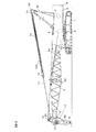
図1〜4を参照して、本発明によるリービング装置およびロープワイヤリング方法の一実施の形態を説明する。図1は、本発明によるリービング装置を搭載したクレーンの側面図である。このクレーン100は、走行体1と、旋回輪2を介して走行体上に旋回可能に搭載された旋回体3と、旋回体3のフレーム(旋回フレーム)に前後方向に起伏可能に軸支されたブーム4とを有する。旋回体3には主巻ウインチ(メインウインチ)5、リービングウインチ6、および起伏ウインチ7が配設され、旋回体3の後端部にはカウンタウエイト8が支持されている。メインウインチ5のメインドラムには主巻ロープ(メインロープ)5aが巻回され、リービングウインチ6のリービングドラムにはリービングロープ6aが巻回され、起伏ウインチ7の起伏ドラムには起伏ロープ7aが巻回されている。ブーム4の後方の旋回体3にはAフレーム30(ガントリとも呼ぶ)が立設されている。
With reference to FIGS. 1-4, one Embodiment of the reeving apparatus and rope wiring method by this invention is described. FIG. 1 is a side view of a crane equipped with a reeving device according to the present invention. The
ブーム4の先端にはポイントシーブ14が設けられ、ブーム4先端近傍の上部にはガイドシーブ15が設けられている。ブーム4先端近傍の下部には、ロープソケット取付部16と、ロープガイド20とが設けられている。ブーム4の先端部と基端部の中間位置近傍の下部にはガイドローラ25が設けられている。ロープソケット取付部16は、メインロープ5aの先端に接続されたロープソケット17が取り付けられる部分である。ロープガイド20およびガイドローラ25は、後述するようにリービング作業時にリービングロープ6aを案内するローラである。
A
メインロープ5aはブーム先端近傍のガイドシーブ15を経由して、吊具であるフック9のシーブ(フックシーブ)9aおよびポイントシーブ14に掛け回されており、その先端部分は上述のようにロープソケット17を介してロープソケット取付部16に取り付けられている。メインウインチ5が駆動されるとフック9が昇降する。ブーム先端部にはペンダントロープ11の一端が接続され、ペンダントロープ11の他端はブライドル12に接続されている。Aフレーム30の頂部には回動可能にハンガ13が取り付けられ、起伏ロープ7aはAフレーム頂部のシーブ32を経由してブライドル12とハンガ13の間に複数回掛け回されている。この状態で起伏ドラム7を駆動するとハンガ13とブライドル12の間隔が変化し、ペンダントロープ11を介してブーム4が起伏する。
The
−−−ロープガイド20およびガイドローラ25について−−−
図2(a)は、後に詳述するリービング作業中のクレーン100の側面図である。図2(b)は、図2(a)のA矢視断面図であり、ロープガイド20の構造を示している。ロープガイド20は、ブーム4の左右のフレームに設けられた穴4aに挿通されるシャフト21と、ブーム4の左右のフレームの間で、シャフト21によって回動可能に軸支される中空シャフト22とを有する。シャフト21には抜け止め23が施され、シャフト21および中空シャフト22がブーム4から脱落しないように構成されている。シャフト21は、ブーム4の先端近傍に取り付けられるため、軽量であることが望ましい。そこで、シャフト21を中空の軸状部材で構成してもよい。また、ブーム4の左右のフレームと中空シャフト22の端面との間でリービングロープ6aが挟まらないように、中空シャフト22の長さは適宜設定されている。
--- About
FIG. 2A is a side view of the
ロープガイド20は、上述のようにブーム4の先端近傍の下部で、ロープソケット取付部16の近傍に設けられている。これは、後述するようにリービング作業において、リービングロープ6aでメインロープ5aを引き込む際に、リービングロープ6aおよびメインロープ5aをフック9の上方へ向かって引き出すことで、リービングロープ6aやメインロープ5aがフックシーブ9aのとば口へ当たってリービングロープ6aやメインロープ5a、フック9を痛めてしまうことを防止するためである。また、ロープガイド20は、クレーン作業に支障がないようにするため、およびロープガイド20の破損を防止するために、たとえば略80度程度の傾斜角度にまでブーム4を起立させてもフック9を吊っているメインロープ5aが当たらないような位置に設けられている。
As described above, the
ガイドローラ25は、上述のようにブーム4の先端部と基端部の中間位置近傍の下部に設けられており、リービング作業中にリービングロープ6aがブーム4に接触するのを防止する。ガイドローラ25もロープガイド20と同様の構造である。
As described above, the
−−−リービング作業について−−−
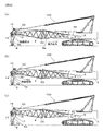
このように構成されるクレーン100では、クレーン100を作業現場で組み立てる際に、リービング作業を次のように行う。図3および図4を参照して、以下にリービング作業について説明する。リービング作業の開始直前には、図3(a)に示すように、メインロープ5aおよびリービングロープ6aは、メインウインチ5およびリービングウインチ6に巻き取られた状態となっている。リービング作業では、最初にクレーン100のブーム4を前傾させて、ブーム4の先端を地面に近づけた状態にしておく。このとき、フック9は地面に起立させた状態で置いておく。そして、ポイントシーブ14がフック9の略直上に位置するようにクレーン100またはフック9の位置を調節する。
--- Leaving work ---
In the
次いで、図3(b)に示すように、リービングウインチ6を駆動させてリービングロープ6aを巻き出して、ブーム4の下部に沿って前方へ引き出し、ガイドローラ25の下部からロープガイド20の上方を通し、ロープガイド20から下方へ向けてフックシーブ9aおよびポイントシーブ14へ掛け回す。リービングロープ6aを各部に通す順番、方向は、メインロープ5aを各部に通す順番、方向とは逆である。これは、リービングロープ6aでメインロープ5aを導いたときに、メインロープ5aが各部を正しい順番、方向で導かれるようにするためである。
Next, as shown in FIG. 3 (b), the reeving winch 6 is driven to unwind the
さらにリービングウインチ6を駆動させて、ポイントシーブ14へ掛け回したリービングロープ6aをガイドシーブ15を経由してメインウインチ5の近傍まで引き出し、図3(c)に示すように、その先端をメインロープ5aの先端と接続する。そして、メインウインチ5を駆動してメインロープ5aを所定の速度で繰り出すとともに、リービングウインチ6を駆動してリービングロープ6aを巻き取る。これにより、メインロープ5aがリービングロープ6aによって導かれて、ガイドシーブ15を経由して、フックシーブ9aおよびポイントシーブ14に掛け回される。
Further, the reeving winch 6 is driven, and the
このようにロープガイド20の上方を通したリービングロープ6aでメインロープ5aを導くことで、リービングロープ6aおよびメインロープ5aがフック9の上方へ向かって引き出されるので、リービングロープ6aおよびメインロープ5aがフックシーブ9aのとば口へ当たることを防止できる。また、リービングロープ6aおよびメインロープ5aが起立しているフック9の上方に向かって引き出されるので、フック9を倒そうとする力がほとんど作用せず、フック9を安定的に起立させたままとすることができる。
By guiding the
図4(a)に示すように、リービングロープ6aとメインロープ5aとの接続部分がロープガイド20の近傍まで導かれたら、メインウインチ5およびリービングウインチ6を停止させて、図4(b)に示すように、リービングロープ6aとメインロープ5aとの接続を解く。そして、図4(c)に示すように、メインロープ5aの先端をロープソケット17に接続し、ロープソケット17をロープソケット取付部16に取り付ける。そして、繰り出されているリービングロープ6aをリービングウインチ6で巻き取る。以上でリービング作業が終了する。
As shown in FIG. 4 (a), when the connecting portion between the leaving
上述したクレーン100では、次の作用効果を奏する。
(1) ブーム4の先端近傍に、リービングウインチ6からブーム4の下面に沿って引き回され、フックシーブ9aへ至るリービングロープ6aを案内するロープガイド20を設けるように構成した。これにより、リービング作業時に、リービングロープ6aおよびメインロープ5aがフック9の上方へ向かって引き出されるので、フック9を立てたままでリービング作業が行える。したがって、リービングロープ6aおよびメインロープ5aがフックシーブ9aのとば口へ当たることを防止できるとともに、リービングロープ6aやメインロープ5a、フック9に無理な力がほとんど加わらないので、これらを痛めることを防止できる。
The
(1) A
また、リービングロープ6aおよびメインロープ5aが起立しているフック9の上方に向かって引き出されるので、フック9を倒そうとする力がほとんど作用せず、フック9を安定的に起立させたまま安全にリービング作業を行える。さらに、リービングロープ6aおよびメインロープ5aの通し方に無理がないので、リービング作業時にリービングロープ6aおよびメインロープ5aを通す速度を必要以上に落とさなくてもよく、リービング作業を効率的に実施できる。また、フック9を立てたままでリービング作業が行えるので、リービング作業後に横倒しにしてあるフック9を立てる必要がない。これにより、横倒しにしてあるフック9を立てることで発生する恐れのあるフック9やメインロープ5aの損傷を防止できる。
In addition, since the
(2) ロープガイド20をロープソケット取付部16の近傍に設けるように構成した。これにより、クレーン作業時におけるフック9とロープソケット取付部16との位置関係と略同じ位置関係となるようなロープガイド20に向かって、リービング作業時にリービングロープ6aやメインロープ5aがフックシーブ9aから引き出されるので、リービングロープ6aやメインロープ5a、フック9に無理な力が加わらず、これらを痛めることを極力防止できる。また、リービング作業によって、メインロープ5aの先端が、これをロープソケット17を介して取り付けるロープソケット取付部16の近傍に引き出されるので、ロープソケット取付部16への取り付け作業が容易となり効率的である。
(2) The
(3) ロープガイド20を、たとえば略80度程度の傾斜角度にまでブーム4を起立させてもフック9を吊っているメインロープ5aが当たらないような位置に設けるように構成した。これにより、クレーン作業において、ロープガイド20とメインロープ5aとの接触、干渉を防止でき、クレーン作業に支障がなく、ロープガイド20の破損を防止できる。
(3) The
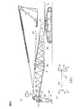
−−−変形例−−−
(1) 上述の説明では、リービングウインチ6を旋回体3上に設けているが、本発明はこれに限定されない。たとえば、図5に示すように、リービングウインチ6をブーム4側に設けるように構成してもよく、上述した作用効果と同様の作用効果を奏する。なお、ブーム4の先端側の重量増を避けること、およびリービングウインチ6への圧油を旋回体3側から供給することを考慮して、リービングウインチ6はブーム4の基端側に近いところに設けることが望ましい。
---- Modified example ---
(1) Although the leaving winch 6 is provided on the revolving
(2) 上述の説明では、ロープガイド20をロープソケット取付部16の近傍に設けるように構成したが、本発明はこれに限定されない。たとえば、リービング作業において、リービングロープ6aでメインロープ5aを引き込む際に、リービングロープ6aやメインロープ5aがフックシーブ9aのとば口などに当たらないように、リービングロープ6aおよびメインロープ5aをフック9の上方へ向かって引き出すことができれば、ブーム4の先端近傍の任意の位置に設けることができる。なお、フック9を立てた状態で安定的にリービング作業が行えるように、リービングロープ6aでメインロープ5aを引き込む際に、リービングロープ6aの牽引力に起因してフック9を転倒させようとするモーメントが、ある程度の安全率をも加味した上で、起立しているフック9が転倒を開始するモーメントよりも小さくなるように、ロープガイド20の設置位置を決める必要がある。また、ロープガイド20は、クレーン作業に支障がなく、ロープガイド20の破損を防止するために、たとえば略80度程度の傾斜角度にまでブーム4を起立させてもフック9を吊っているメインロープ5aが当たらないような位置に設けられることが望ましい。
(2) In the above description, the
また、ロープガイド20をロープソケット取付部16に取り付けてリービング作業を行い、リービング作業終了後には、ロープガイド20をロープソケット取付部16から取り外し、メインロープ5aの先端をロープソケット17を介してロープソケット取付部16に取り付けるようにしてもよい。
(3) 上述した各実施の形態および変形例は、それぞれ組み合わせてもよい。
Further, the
(3) You may combine each embodiment and modification which were mentioned above, respectively.
なお、本発明は、上述した実施の形態のものに何ら限定されず、リービングロープを巻き取りおよび繰り出すリービングウインチと、ブーム先端に設けられて、リービングウインチからブーム下面に沿って引き回され、吊具のシーブへ至るリービングロープを案内するガイドとを備えることを特徴とする各種構造のリービング装置、および、このリービング装置を備える各種構造のクレーンを含むものである。また、本発明は、上述した実施の形態のものに何ら限定されず、リービングウインチに巻き掛けられているロープであってメインロープよりも径の小さいリービングロープをブームの下面から、吊具およびブームの先端に設けられたトップシーブを経てメインウインチへ引き回し、リービングロープの先端をメインウインチに巻き取られているメインロープの先端に接続し、リービングウインチでリービングロープを巻き取ることでメインロープを吊具のシーブに掛け回すロープワイヤリング方法において、トップシーブとブームの基端との間のブーム先端に設けられたリービングロープガイドを経由して、リービングロープをリービングウインチから吊具のシーブへ引き回すことを特徴とする各種のロープワイヤリング方法を含むものである。 The present invention is not limited to the embodiment described above, and is provided at the tip of the boom by winding and unwinding the reeving rope, and is hung from the leaving winch along the bottom surface of the boom. And a guide for guiding a leaving rope leading to the sheave of the tool, and a cleaving device having various structures, and a crane having various structures having the leaving device. Further, the present invention is not limited to the above-described embodiment, and a rope that is wound around a reving winch and has a diameter smaller than that of the main rope is connected to the hanger and the boom from the lower surface of the boom. The main rope is routed to the main winch through the top sheave provided at the tip of the main rope, the tip of the reeving rope is connected to the tip of the main rope wound on the main winch, and the main rope is suspended by winding the reeving rope with the leaving winch In the rope wiring method that hangs around the sheave of the implement, the reving rope is routed from the leaving winch to the sheave of the lifting device via the reving rope guide provided at the tip of the boom between the top sheave and the base end of the boom. Includes various rope wiring methods characterized .
1 走行体 2 旋回輪
3 旋回体 4 ブーム
5 主巻ウインチ(メインウインチ) 5a 主巻ロープ(メインロープ)
6 リービングウインチ 6a リービングロープ
9 フック 9a フックシーブ
14 ポイントシーブ 15 ガイドシーブ
16 ロープソケット取付部 17 ロープソケット
20 ロープガイド 25 ガイドローラ
100 クレーン
DESCRIPTION OF
6 Leaving
Claims (5)
ブーム先端に設けられて、前記リービングウインチから前記ブーム下面に沿って引き回され、吊具のシーブへ至る前記リービングロープを案内するガイドとを備えることを特徴とするリービング装置。 A leaving winch for winding and unwinding the leaving rope;
A reeving device comprising: a guide provided at a tip of the boom, and a guide for guiding the reeving rope that is routed along the bottom surface of the boom from the reving winch to reach a sheave of a hanging tool.
前記ガイドは、主巻きウインチによって巻き取られおよび繰り出されるメインロープの端部の取付位置近傍に設けられていることを特徴とするリービング装置。 The reeving device according to claim 1, wherein
The said guide is provided in the attachment position vicinity of the edge part of the main rope wound up and drawn | fed out by the main winding winch, The reeving apparatus characterized by the above-mentioned.
前記ガイドは、前記ブームを起立させても前記メインロープと干渉しない位置に設けられていることを特徴とするリービング装置。 The reeving device according to claim 2, wherein
The reeving device according to claim 1, wherein the guide is provided at a position that does not interfere with the main rope even when the boom is raised.
ブームと、
メインロープを巻き取りおよび繰り出す主巻きウインチと、
前記メインロープが掛け回された吊具とを備えることを特徴とするクレーン。 The reeving device according to any one of claims 1 to 3,
The boom,
A main winding winch for winding and unwinding the main rope;
A crane comprising: a hanging tool around which the main rope is hung.
前記トップシーブと前記ブームの基端との間の前記ブーム先端に設けられたリービングロープガイドを経由して、前記リービングロープを前記リービングウインチから前記吊具のシーブへ引き回すことを特徴とするロープワイヤリング方法。 A rope that is wound around a reving winch and that is smaller in diameter than the main rope is routed from the lower surface of the boom to the main winch through a suspension and a top sheave provided at the tip of the boom, and the reving rope In the rope wiring method of connecting the tip of the main rope that is wound around the main winch and winding the main rope around the sheave of the hanging tool by winding the leave rope with the leaving winch.
Rope wiring, wherein the rope is routed from the leaf winch to the sheave of the suspension via a leaf rope guide provided at a tip of the boom between the top sheave and a base end of the boom. Method.
Priority Applications (1)
| Application Number | Priority Date | Filing Date | Title |
|---|---|---|---|
| JP2009150912A JP5296614B2 (en) | 2009-06-25 | 2009-06-25 | Leaving device, crane and rope wiring method |
Applications Claiming Priority (1)
| Application Number | Priority Date | Filing Date | Title |
|---|---|---|---|
| JP2009150912A JP5296614B2 (en) | 2009-06-25 | 2009-06-25 | Leaving device, crane and rope wiring method |
Publications (2)
| Publication Number | Publication Date |
|---|---|
| JP2011006199A true JP2011006199A (en) | 2011-01-13 |
| JP5296614B2 JP5296614B2 (en) | 2013-09-25 |
Family
ID=43563362
Family Applications (1)
| Application Number | Title | Priority Date | Filing Date |
|---|---|---|---|
| JP2009150912A Expired - Fee Related JP5296614B2 (en) | 2009-06-25 | 2009-06-25 | Leaving device, crane and rope wiring method |
Country Status (1)
| Country | Link |
|---|---|
| JP (1) | JP5296614B2 (en) |
Cited By (3)
| Publication number | Priority date | Publication date | Assignee | Title |
|---|---|---|---|---|
| JP2015113225A (en) * | 2013-12-16 | 2015-06-22 | 日本車輌製造株式会社 | Replacement method for auxiliary hoist rope |
| JP2018167972A (en) * | 2017-03-30 | 2018-11-01 | コベルコ建機株式会社 | Wiring method and crane |
| JP2020164278A (en) * | 2019-03-29 | 2020-10-08 | コベルコ建機株式会社 | Rope wiring method and guide sheave device for work machine |
Citations (2)
| Publication number | Priority date | Publication date | Assignee | Title |
|---|---|---|---|---|
| JP2000053383A (en) * | 1998-08-14 | 2000-02-22 | Hitachi Constr Mach Co Ltd | Hydraulic drum driving device |
| JP3225677B2 (en) * | 1993-04-07 | 2001-11-05 | コベルコ建機株式会社 | Excavator hanging rope guide device |
-
2009
- 2009-06-25 JP JP2009150912A patent/JP5296614B2/en not_active Expired - Fee Related
Patent Citations (2)
| Publication number | Priority date | Publication date | Assignee | Title |
|---|---|---|---|---|
| JP3225677B2 (en) * | 1993-04-07 | 2001-11-05 | コベルコ建機株式会社 | Excavator hanging rope guide device |
| JP2000053383A (en) * | 1998-08-14 | 2000-02-22 | Hitachi Constr Mach Co Ltd | Hydraulic drum driving device |
Cited By (4)
| Publication number | Priority date | Publication date | Assignee | Title |
|---|---|---|---|---|
| JP2015113225A (en) * | 2013-12-16 | 2015-06-22 | 日本車輌製造株式会社 | Replacement method for auxiliary hoist rope |
| JP2018167972A (en) * | 2017-03-30 | 2018-11-01 | コベルコ建機株式会社 | Wiring method and crane |
| JP2020164278A (en) * | 2019-03-29 | 2020-10-08 | コベルコ建機株式会社 | Rope wiring method and guide sheave device for work machine |
| JP7287055B2 (en) | 2019-03-29 | 2023-06-06 | コベルコ建機株式会社 | ROPE WIRING METHOD AND GUIDE SHEAVE DEVICE FOR WORKING MACHINE |
Also Published As
| Publication number | Publication date |
|---|---|
| JP5296614B2 (en) | 2013-09-25 |
Similar Documents
| Publication | Publication Date | Title |
|---|---|---|
| JP4225344B2 (en) | crane | |
| EP1854759B1 (en) | Boom hoisting device of a crane | |
| JP2010241604A5 (en) | ||
| JP5296614B2 (en) | Leaving device, crane and rope wiring method | |
| CN108149928A (en) | The tower end installation method of suspension cable | |
| JP6645222B2 (en) | How to attach a crane jib | |
| JP2011190084A (en) | Assembling method for crane attachment | |
| JP2004075294A (en) | Jib strut self-assembling method for tower crane | |
| JP6414578B2 (en) | Rope feeding device | |
| JP2018122999A (en) | Gib mooring method and gib mooring device | |
| JP6686781B2 (en) | Top spreader mounting method and crane | |
| JP6558399B2 (en) | crane | |
| JP6969281B2 (en) | Crane and crane disassembly method | |
| JP4600374B2 (en) | Crane boom head | |
| JP6787223B2 (en) | Wiring method and crane | |
| JP6166940B2 (en) | Lifting method and lifting assist device using crane | |
| JP2020164278A (en) | Rope wiring method and guide sheave device for work machine | |
| JP5060867B2 (en) | Fixing method of pile driver and hoisting rope | |
| JP7275703B2 (en) | front strut backstop | |
| JP2003128367A (en) | Rope extension method at climbing of lifting device and its auxiliary device | |
| JP2019052000A (en) | Mooring method of jib and mooring device of jib | |
| JP3182333B2 (en) | Pile driver leader lifting suspension equipment | |
| JP2018162125A (en) | Tower crane | |
| JP6765326B2 (en) | Construction machinery | |
| JP7322528B2 (en) | Jib mooring device |
Legal Events
| Date | Code | Title | Description |
|---|---|---|---|
| A621 | Written request for application examination |
Free format text: JAPANESE INTERMEDIATE CODE: A621 Effective date: 20110801 |
|
| A977 | Report on retrieval |
Free format text: JAPANESE INTERMEDIATE CODE: A971007 Effective date: 20130313 |
|
| A131 | Notification of reasons for refusal |
Free format text: JAPANESE INTERMEDIATE CODE: A131 Effective date: 20130326 |
|
| A521 | Request for written amendment filed |
Free format text: JAPANESE INTERMEDIATE CODE: A523 Effective date: 20130523 |
|
| TRDD | Decision of grant or rejection written | ||
| A01 | Written decision to grant a patent or to grant a registration (utility model) |
Free format text: JAPANESE INTERMEDIATE CODE: A01 Effective date: 20130611 |
|
| A61 | First payment of annual fees (during grant procedure) |
Free format text: JAPANESE INTERMEDIATE CODE: A61 Effective date: 20130613 |
|
| R150 | Certificate of patent or registration of utility model |
Ref document number: 5296614 Country of ref document: JP Free format text: JAPANESE INTERMEDIATE CODE: R150 Free format text: JAPANESE INTERMEDIATE CODE: R150 |
|
| S533 | Written request for registration of change of name |
Free format text: JAPANESE INTERMEDIATE CODE: R313533 |
|
| R350 | Written notification of registration of transfer |
Free format text: JAPANESE INTERMEDIATE CODE: R350 |
|
| LAPS | Cancellation because of no payment of annual fees |