JP2010516482A - Metal cutting system that effectively supplies cutting fluid - Google Patents
Metal cutting system that effectively supplies cutting fluid Download PDFInfo
- Publication number
- JP2010516482A JP2010516482A JP2009546381A JP2009546381A JP2010516482A JP 2010516482 A JP2010516482 A JP 2010516482A JP 2009546381 A JP2009546381 A JP 2009546381A JP 2009546381 A JP2009546381 A JP 2009546381A JP 2010516482 A JP2010516482 A JP 2010516482A
- Authority
- JP
- Japan
- Prior art keywords
- insert
- cutting
- shim
- clamp
- tool holder
- Prior art date
- Legal status (The legal status is an assumption and is not a legal conclusion. Google has not performed a legal analysis and makes no representation as to the accuracy of the status listed.)
- Pending
Links
Images


Classifications
-
- B—PERFORMING OPERATIONS; TRANSPORTING
- B23—MACHINE TOOLS; METAL-WORKING NOT OTHERWISE PROVIDED FOR
- B23B—TURNING; BORING
- B23B27/00—Tools for turning or boring machines; Tools of a similar kind in general; Accessories therefor
- B23B27/10—Cutting tools with special provision for cooling
-
- B—PERFORMING OPERATIONS; TRANSPORTING
- B23—MACHINE TOOLS; METAL-WORKING NOT OTHERWISE PROVIDED FOR
- B23B—TURNING; BORING
- B23B27/00—Tools for turning or boring machines; Tools of a similar kind in general; Accessories therefor
- B23B27/14—Cutting tools of which the bits or tips or cutting inserts are of special material
- B23B27/16—Cutting tools of which the bits or tips or cutting inserts are of special material with exchangeable cutting bits or cutting inserts, e.g. able to be clamped
- B23B27/1625—Cutting tools of which the bits or tips or cutting inserts are of special material with exchangeable cutting bits or cutting inserts, e.g. able to be clamped with plate-like cutting inserts of special shape clamped by a clamping member acting almost perpendicularly on the chip-forming plane
- B23B27/164—Cutting tools of which the bits or tips or cutting inserts are of special material with exchangeable cutting bits or cutting inserts, e.g. able to be clamped with plate-like cutting inserts of special shape clamped by a clamping member acting almost perpendicularly on the chip-forming plane characterised by having a special shape
-
- B—PERFORMING OPERATIONS; TRANSPORTING
- B23—MACHINE TOOLS; METAL-WORKING NOT OTHERWISE PROVIDED FOR
- B23B—TURNING; BORING
- B23B2205/00—Fixation of cutting inserts in holders
- B23B2205/16—Shims
-
- Y—GENERAL TAGGING OF NEW TECHNOLOGICAL DEVELOPMENTS; GENERAL TAGGING OF CROSS-SECTIONAL TECHNOLOGIES SPANNING OVER SEVERAL SECTIONS OF THE IPC; TECHNICAL SUBJECTS COVERED BY FORMER USPC CROSS-REFERENCE ART COLLECTIONS [XRACs] AND DIGESTS
- Y10—TECHNICAL SUBJECTS COVERED BY FORMER USPC
- Y10T—TECHNICAL SUBJECTS COVERED BY FORMER US CLASSIFICATION
- Y10T407/00—Cutters, for shaping
- Y10T407/11—Cutters, for shaping including chip breaker, guide or deflector detachable from tool and tool holder
- Y10T407/118—Chip breaker
-
- Y—GENERAL TAGGING OF NEW TECHNOLOGICAL DEVELOPMENTS; GENERAL TAGGING OF CROSS-SECTIONAL TECHNOLOGIES SPANNING OVER SEVERAL SECTIONS OF THE IPC; TECHNICAL SUBJECTS COVERED BY FORMER USPC CROSS-REFERENCE ART COLLECTIONS [XRACs] AND DIGESTS
- Y10—TECHNICAL SUBJECTS COVERED BY FORMER USPC
- Y10T—TECHNICAL SUBJECTS COVERED BY FORMER US CLASSIFICATION
- Y10T407/00—Cutters, for shaping
- Y10T407/14—Cutters, for shaping with means to apply fluid to cutting tool
-
- Y—GENERAL TAGGING OF NEW TECHNOLOGICAL DEVELOPMENTS; GENERAL TAGGING OF CROSS-SECTIONAL TECHNOLOGIES SPANNING OVER SEVERAL SECTIONS OF THE IPC; TECHNICAL SUBJECTS COVERED BY FORMER USPC CROSS-REFERENCE ART COLLECTIONS [XRACs] AND DIGESTS
- Y10—TECHNICAL SUBJECTS COVERED BY FORMER USPC
- Y10T—TECHNICAL SUBJECTS COVERED BY FORMER US CLASSIFICATION
- Y10T407/00—Cutters, for shaping
- Y10T407/22—Cutters, for shaping including holder having seat for inserted tool
- Y10T407/2272—Cutters, for shaping including holder having seat for inserted tool with separate means to fasten tool to holder
- Y10T407/2282—Cutters, for shaping including holder having seat for inserted tool with separate means to fasten tool to holder including tool holding clamp and clamp actuator
-
- Y—GENERAL TAGGING OF NEW TECHNOLOGICAL DEVELOPMENTS; GENERAL TAGGING OF CROSS-SECTIONAL TECHNOLOGIES SPANNING OVER SEVERAL SECTIONS OF THE IPC; TECHNICAL SUBJECTS COVERED BY FORMER USPC CROSS-REFERENCE ART COLLECTIONS [XRACs] AND DIGESTS
- Y10—TECHNICAL SUBJECTS COVERED BY FORMER USPC
- Y10T—TECHNICAL SUBJECTS COVERED BY FORMER US CLASSIFICATION
- Y10T407/00—Cutters, for shaping
- Y10T407/24—Cutters, for shaping with chip breaker, guide or deflector
-
- Y—GENERAL TAGGING OF NEW TECHNOLOGICAL DEVELOPMENTS; GENERAL TAGGING OF CROSS-SECTIONAL TECHNOLOGIES SPANNING OVER SEVERAL SECTIONS OF THE IPC; TECHNICAL SUBJECTS COVERED BY FORMER USPC CROSS-REFERENCE ART COLLECTIONS [XRACs] AND DIGESTS
- Y10—TECHNICAL SUBJECTS COVERED BY FORMER USPC
- Y10T—TECHNICAL SUBJECTS COVERED BY FORMER US CLASSIFICATION
- Y10T408/00—Cutting by use of rotating axially moving tool
- Y10T408/44—Cutting by use of rotating axially moving tool with means to apply transient, fluent medium to work or product
Abstract
金属切削システムは、工具ホルダ(1)、シム(3)、上部凹部(15)を備えたインサート(10)、上部部品(18)、およびクランプを有する。流体供給用のすくい面冷却チャネル(21)は、上部部品(18)とインサートの凹部(15)との間に形成される。すくい面冷却チャネル(21)の端部にある主放出スロット(27)は、インサートの切刃(16)の下から流体を供給する。流体を逃げ面(12)に供給する第2の冷却チャネル(9)は、インサート(10)とシムとの間に形成されるか、またはシム(3)と工具ホルダ(1)との間に形成され、冷却チャネルの一部はシム(3)を貫通する。 The metal cutting system has a tool holder (1), a shim (3), an insert (10) with an upper recess (15), an upper part (18), and a clamp. A rake face cooling channel (21) for fluid supply is formed between the upper part (18) and the recess (15) of the insert. A main discharge slot (27) at the end of the rake face cooling channel (21) supplies fluid from under the insert cutting edge (16). A second cooling channel (9) supplying fluid to the flank (12) is formed between the insert (10) and the shim, or between the shim (3) and the tool holder (1). Formed and part of the cooling channel penetrates the shim (3).
Description
本発明は、金属切削システム、特に、金属切削工具と加工物との間の接触部への効果的な切削液(coolant)供給を可能にするように構成された金属切削システムに関する。 The present invention relates to a metal cutting system, and more particularly to a metal cutting system configured to allow an effective coolant supply to a contact between a metal cutting tool and a workpiece.
金属加工作業を行う金属切削工具は通常、面が切刃で終端する切削インサートと、インサートを受け入れるように構成された座で形成された工具ホルダとを含む。切削インサートは、加工物に食い込み、加工物から切り屑を除去する。当然のことながら、金属切削作業における切削インサートの寿命を延ばすことが望ましい。インサートの寿命が長いほど、作業コストが下がり、機械効率が良くなる。切削インサートの寿命に関する1つの要因は、切削作業時のインサートの温度である。インサートの温度が高いほど、インサートの実用寿命が短くなる。 Metal cutting tools that perform metalworking operations typically include a cutting insert whose surface terminates with a cutting edge and a tool holder formed with a seat configured to receive the insert. The cutting insert bites into the workpiece and removes chips from the workpiece. Of course, it is desirable to extend the life of the cutting insert in metal cutting operations. The longer the life of the insert, the lower the operating cost and the better the mechanical efficiency. One factor regarding the life of the cutting insert is the temperature of the insert during the cutting operation. The higher the temperature of the insert, the shorter the service life of the insert.
多くのシステムが、切削時のインサートの温度を下げるように設計されてきた。例えば、切削液は通常、インサートの切刃に向けられたノズルを通じてかけることができる。切削液は、インサートの温度を下げるだけでなく、切削領域から切り屑を除去する働きもする。ノズルは、大抵1〜12インチの距離だけ切刃から離れている。これは、効果的に冷却する距離としては離れすぎている。切削液を吹きつけなければならない距離が遠いほど、切削液は空気とより多く混合し、工具−切り屑の接触部と実際に接触する可能性が低くなる。 Many systems have been designed to reduce the temperature of the insert during cutting. For example, the cutting fluid can usually be applied through a nozzle directed to the cutting edge of the insert. The cutting fluid not only lowers the temperature of the insert but also serves to remove chips from the cutting area. The nozzle is usually separated from the cutting edge by a distance of 1 to 12 inches. This is too far away for effective cooling. The farther the cutting fluid must be sprayed, the more cutting fluid will mix with the air and the less likely it will actually come into contact with the tool-chip contact.
アントン(Antoun)に交付された米国特許第6,045,300号明細書に見られるように、高圧かつ大量の切削液を切刃に向けることで冷却を改善したものがある。そのほかには、インサートと、インサートをホルダに固定するトッププレートとの間に溝を作って、切削液を吹きつけなければならない距離を短くしたものもある。これは、クレーマ(Kraemer)に対する米国特許出願公開第2003/00820118号明細書に見られる。ホン(Hong)に対する米国特許第5,901,623号明細書に見られるように、インサートの切刃の比較的近くに、切削液として液体窒素を供給するものもある。各変形形態では、効果が限定されることが分かった。多くはまだ工具−加工物の接触部から離れて配置されている。トッププレートとインサートとの間に溝がある変形形態では、工具−加工物の接触部に、より近接して流体を運ぶが、十分に接近してはいない。クレーマの設計はまた、流体流れの方向がほとんど完全に一平面に限られるという点で限界がある。ホンの設計と同様の液体窒素システムはある程度の利益を示したものの、ほとんどの用途で非常に高いコストがかかる。金属切削作業時に、インサートを冷却する単純で効果的なアセンブリが依然として必要とされているのは明らかである。 As seen in US Pat. No. 6,045,300 issued to Anton, some have improved cooling by directing high pressure and a large amount of cutting fluid toward the cutting edge. In addition, a groove is formed between the insert and a top plate for fixing the insert to the holder so that the distance that the cutting fluid must be sprayed is shortened. This can be seen in US 2003/00820118 to Kraemer. Some, as seen in US Pat. No. 5,901,623 to Hong, supply liquid nitrogen as a cutting fluid relatively close to the cutting edge of the insert. Each variant has been found to have limited effects. Many are still located away from the tool-workpiece contact. In variants where there is a groove between the top plate and the insert, it carries the fluid closer to the tool-workpiece contact, but not close enough. The Kramer design is also limited in that the direction of fluid flow is almost completely confined to one plane. Although a liquid nitrogen system similar to Hong's design has shown some benefit, it is very expensive for most applications. Clearly, there remains a need for a simple and effective assembly for cooling the insert during metal cutting operations.
本発明者は、従来の冷却装置に関連する課題を認識し、従来の冷却システムと協働して切削液を切削インサートに供給する、先行技術の課題に対処したインサートアセンブリを開発した。 The inventor has recognized problems associated with conventional cooling devices and has developed an insert assembly that addresses the prior art problems of supplying cutting fluid to a cutting insert in cooperation with a conventional cooling system.
本発明の一実施形態では、アセンブリは、切削インサートを受け入れる凹部と切削液供給用の流路とを有する工具ホルダと;切削液をインサートの逃げ面または切刃に供給できる冷却チャネルを有するシムと;インサートの中心にある円錐台形凹部と工具ホルダの切削液流路と一列になったオリフィスとを有する切削インサートと;上面にある凹部と、切削インサートの円錐台形凹部と一列に整列した円錐台形の底部とを備えた上部部品であって、インサートオリフィスからインサートの切刃または角部に近接した放出スロットにわたるすくい面冷却チャネルを除いて、インサートと上部部品との間に流体密封止を形成する上部部品と;冷却チャネルを封止し、切刃と上部部品とを固定できるクランプとを含む。上部部品−インサートの接触面とインサートのすくい面を含む平面とが斜角をなす関係にあるために、すくい面を含む平面の斜め下から切削液を供給することが可能になる。こうして、切削液は切り屑の下面に当たる。本明細書で説明するように、インサートの逃げ面への切削液の供給とすくい面冷却とを組み合わせることにより、インサートを冷却し、切り屑を除去する効率的な手段となることが分かった。結果として、本発明を使用することにより、インサートの寿命が大幅に改善される。 In one embodiment of the present invention, the assembly includes a tool holder having a recess for receiving a cutting insert and a flow path for supplying cutting fluid; a shim having a cooling channel capable of supplying cutting fluid to the flank or cutting edge of the insert; A cutting insert having a frustoconical recess in the center of the insert and a cutting fluid flow path in the tool holder and a line of orifices; An upper part with a bottom part, forming a fluid tight seal between the insert and the upper part, excluding a rake face cooling channel from the insert orifice to the discharge slot adjacent to the cutting edge or corner of the insert A part; and a clamp that seals the cooling channel and secures the cutting edge and the upper part. Since the contact surface of the upper part-insert and the plane including the rake face of the insert form an oblique angle, the cutting fluid can be supplied from diagonally below the plane including the rake face. Thus, the cutting fluid hits the lower surface of the chips. As described herein, it has been found that combining cutting fluid supply to the flank face of the insert with rake face cooling provides an efficient means of cooling the insert and removing chips. As a result, using the present invention greatly improves the life of the insert.
図面を参照してなされる以下の詳細な説明から、本発明のさらなる特徴およびそれらから得られた利点が明らかになるであろう。 Further features of the present invention and advantages derived therefrom will become apparent from the following detailed description made with reference to the drawings.
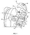
本発明の図1を参照すると、切削インサート10を受け入れる凹部29を有する工具ホルダ1が示されている。工具ホルダ1は、流体切削剤を凹部29に供給する切削液流路2も有する。割り出し可能な切削インサート10は、凹部29に配置される。切削インサート10は、少なくとも1つの逃げ面12、すくい面13、および底面14を有する。逃げ面12とすくい面13との交線は、切刃16を形成している。逃げ面が複数ある場合、2つの隣接する逃げ面12とすくい面13との交点は、切削角部17を形成する。当然のことながら、丸い切削インサートは、2つの隣接する逃げ面を含まず、したがって、切削角部はない。丸い切削インサートには切削角部がないが、いずれにしても、切刃があるのは当然のことである。インサート凹部15は、インサート10のすくい面13に配置されている。インサート凹部15は、インサート凹部15を囲み、切刃16と、適宜切削角部17とを含むすくい面13の残りの部分よりも低い、すくい面13内の領域とされる。一実施形態では、切刃16および切削角部はすべて同じ平面内にある。切刃の中には、高さが互いに上にあったり、下にあったりするものもあり得るのは明らかであろう。例えば、これは、平坦ではないすくい面を備えた楕円形状のインサートが、金属切削システムでインサートとして使用された場合に当てはまる。
Referring to FIG. 1 of the present invention, a tool holder 1 having a recess 29 for receiving a
インサート10は、工具ホルダ1の切削液流路2と一列に整列して、切削液を受け入れるインサートオリフィス11を有する。インサートオリフィス11は、すくい面13および底面14の両方に通じている。上部部品18は、インサート10に隣接する。上部部品18は、クランプ側20およびインサート側19を有する。上部部品18のインサート側19は、形状がインサート凹部15と一致しているので、この2つを合わせて位置決めすることで封止が形成される。上部部品はまた、インサート側19に(図5に図示)貯蔵器34を有する。貯蔵器34は、インサートオリフィス11と一列に整列する、上部部品18のインサート側19にある空洞である。貯蔵器34は、切削液を上部部品18に配送する。上部部品18はまた、少なくとも1つのすくい面冷却チャネル21を有する。すくい面冷却チャネル21は、上部部品18のインサート側19に形成された、貯蔵器34から適宜切刃16かまたは切削角部17に最も近い、上部部品18上の地点に延びる溝である。すくい面冷却チャネル21を見るには図5を参照されたい。上部部品18がインサート凹部15に取り付けられると、すくい面冷却チャネル21は、インサート凹部15で封止されて、切刃16または切削角部17への切削液経路を形成する。すくい面冷却チャネル21は、上部部品18のインサート側19で封止された、インサート凹部15内の溝で形成できるとも考えられる。クランプ23は、上部部品凹部22に圧力を加える。クランプ23により、上部部品18とインサート10と工具ホルダ1との間の整列および封止が維持される。当然のことながら、クランプ23のタイプは、図に示した方式に限定されるものではない。むしろ、クランプ23は、当技術分野で公知のタイプの、他の適切なクランプ方式を含むことができる。
The
図7に示すように、インサート10が加工物30に食い込むと、切り屑31は、切刃16または切削角部17において、加工物から離れる方向に持ち上げられる。上部部品18とインサート凹部15とが一致した関係にあるため、すくい面13と切り屑31との交線の斜め下から、切削液が供給されるように切削液を案内するすくい面冷却チャネル21が形成される。この供給角により、切削液は切り屑の下面に当たり、その結果、冷却および切り屑の除去が改善される。すくい面冷却チャネル21は、貯蔵器34から切刃に最も近い地点にわたっている。主放出スロット27は、切刃16または切削角部17に最も近い、すくい面冷却チャネル21の端部に形成されている。主放出スロット27が切刃16または角部17より下に位置することは、本発明の重要な態様である。この説明における「切刃より下に」またはこの説明における「切削角部より下に」とは、概ねクランプの方に向かう「切刃より上に」または「切削角部より上に」とは反対の、概ね凹部29の方に向かうことを意味する。主放出スロット27が、切り屑から約0.100インチ以内にあると、冷却および切り屑除去が最も効率的になる。
As shown in FIG. 7, when the
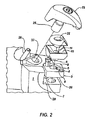
図2および図5に示す別の実施形態では、上面8および底面36を有するシム3が、工具ホルダ1とインサート10との間に配置されている。シム3は、底面36が工具ホルダ1に当接し、上面がインサート10に当接するような向きに置かれている。シムピン6は、シムピン穴5および工具ホルダピン穴7に挿入されている。シムピン6は、工具ホルダ1とインサート10との間のシム3の整列を維持する。シムオリフィス4は、シム3の中心を貫通して形成されている。シムオリフィス4は、切削液が工具ホルダ1の切削液流路2からインサートオリフィス11に進む経路を形成している。逃げ面冷却チャネル9の一部を形成するスロットは、シム3の上面8に設けられている。インサート底面14は、シム3の上面8にある露出したスロットを封止して、逃げ面冷却チャネル9を形成している。逃げ面冷却チャネル9は、シムオリフィス4から、切刃16または切削角部17に最も近い、ほぼシム3の外側部分あたりにわたっている。切刃に最も近い逃げ面冷却チャネル9の端部は、切削液をインサート10の切刃16、切削角部17、または逃げ面12に向けて案内するように、ベース部が湾曲している。
In another embodiment shown in FIGS. 2 and 5, a shim 3 having a
示した実施形態では、インサート10は、すくい面13から底面14に、浅い角度で内側に傾斜した逃げ面12および逃げ面エッジ32を有する。このように、シム3の幅は、底面14の幅よりも短く、すくい面13の幅よりも短くなる。このテーパは、逃げ面12および逃げ面エッジ16を切削液にさらすことを意図しているという事実に留意されたい。インサート10にテーパをつけることにより、逃げ面冷却チャネル9の一部を露出させて、副放出穴28を形成することができ、したがって、インサート10の逃げ面に沿って切削液を排出することが可能になる。
In the illustrated embodiment, the
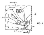
図3に示す第3の実施形態は、上部部品18にジェット部33を増設している。ジェット部33は、切削液流量を増大し、工具−切り屑の接触部に、より多くの流体を効果的に向ける補助的な切削液管である。ジェット部33は、貯蔵器34から上部部品18のクランプ側20の放出点に延び、この放出点から、切削液を工具−切り屑の接触部に向けることができる。
In the third embodiment shown in FIG. 3, the
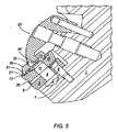
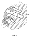
本発明の代替の実施形態が図4および図6に示されている。この実施形態では、逃げ面およびすくい面冷却を提供して最も多い切削液流量が得られる。このアセンブリでは、シム3は、工具ホルダピン穴7を有する工具ホルダ1の凹部29に置かれている。シム3は、シムオリフィス4およびシムピン穴5を有する。シムピン6はねじを切られていて、シムピン穴5を通って、同様にねじを切られた工具ホルダピン穴7に延びている。この構成により、シム3は凹部29に対して整列した状態に維持される。高容量逃げ面冷却チャネル35が、工具ホルダ1とシム3との間に形成されている。高容量逃げ面冷却チャネル35の一部は、シム3の底面36にある溝によって形成されている。この溝は、工具ホルダ1の凹部29にも形成されている。溝は工具ホルダ1の凹部29によって閉じられて、切削液供給用の流路を形成している。高容量逃げ面冷却チャネル35は、シムオリフィス4で始まり、工具ホルダ1とシム3との間の接触面に沿って途中まで延び、次いで、シム3の胴体を通って、インサート10の逃げ面12または逃げ面エッジ32に向かって突出し、インサート10の切刃16または切削角部17に最も近接したシム3の角部にある副放出穴28で終わる。
An alternative embodiment of the present invention is shown in FIGS. This embodiment provides flank and rake surface cooling to provide the highest cutting fluid flow rate. In this assembly, the shim 3 is placed in a recess 29 of the tool holder 1 having a tool holder pin hole 7. The shim 3 has a shim orifice 4 and a
インサート10は、副放出穴28から十分な切削液が流れ出るのを可能にする、傾斜した逃げ面12および逃げ面エッジ32を有する。インサートオリフィス11は、シムオリフィス4と一列に整列している。インサート底面14は、シム3に着座して流体密封止を形成している。インサート凹部15は、円錐台形状とされ、上部部品18のインサート側19と嵌合して流体密封止を形成している。上部部品18のインサート側19も円錐台形状である。貯蔵器は、インサート側19の中心部分に配置され、インサートオリフィス11と一列に整列している。貯蔵器11、インサートオリフィス11、シムオリフィス4、および切削液流路2が一列に整列することにより、切削液が高容量逃げ面冷却チャネル35、すくい面冷却チャネル21、およびジェット部33に自由に流れることができるチャンバが形成される。好ましい実施形態では、すくい面冷却チャネル21は、貯蔵器34から、切刃16または切削角部17より約0.100インチ以内に延びている。上部部品18のインサート側19で、貯蔵器34とは反対側にある、すくい面冷却チャネル21の端部にニブ42がある。ニブ42は、切削液が主放出スロット27から出るときに切削液の流れを妨害する、インサート側から突出した隆起である。ニブ42を見る場合、図9に最も明瞭に示されている。ニブ42により、切削液は、ニブ42がない場合に発生するあまり望ましくない集中した流れではなくて、主放出スロット27から広範囲に拡散される。すくい面冷却チャネルは、切り屑がチャネルに入らないようにしながら、流れを最大限にするのに十分な大きさとなるように作られている。2つのジェット部33は、貯蔵器34から、切削液を切刃16または切削角部17に向けるクランプ側20の出口点に延びている。上部部品凹部22はクランプ側20にある。クランプ23は、上部部品凹部22と係合してインサート10を着座させ、すべての切削液ダクトの流体密封止を維持するクランプヘッド24を有する。好ましい実施形態では、クランプねじ25が、上部部品18の方向でクランプヘッド24に圧力を加える。クランプピン26は、クランプヘッド24の整列を維持する。特定のクランプアセンブリが図1〜6および図8に示されているが、当然のことながら、上部部品、インサート10、およびシム3を凹部29に確実に保持できる任意の適切なクランプアセンブリで十分である。これらのクランプアセンブリの多くは市販されており、当技術分野において公知である。
The
好ましい実施形態では、すべての切削液流路の全流量は、制約されないフラッドノズルからの可能な流量の80%以上とすべきである。 In a preferred embodiment, the total flow rate of all cutting fluid channels should be at least 80% of the possible flow rate from an unconstrained flood nozzle.
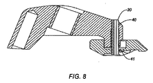
当然のことながら、上部部品18をクランプ23に固定した場合に、幾つかの取り扱い上の利点が見られた。この構成により、アセンブリを取り外すかまたは取り付けるときに、作業者が上部部品を誤って落とす可能性が低くなる。上部部品18をクランプ23に固定する最も有効な方法は、スロット付のスプリングピン39を用いることである。スロット付のスプリングピン39は、図8に示すように、一列に整列したクランプ穴40および上部部品穴41に挿入される。部品同士を固定する他の手段も可能であるが、スロット付のスプリングピン39を使用すると、上部部品18をスロット付のスプリングピン39の主軸のまわりにある程度回転させることができる。この構成により、上部部品18を様々な向きのインサート10と整列させることができる。
Of course, several handling advantages were seen when the
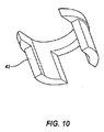
心出しスタッド43は、上部部品18とインサート10の間に組み込むことができる。心出しスタッド43は、貯蔵器34に取り付けられ、インサートオリフィス11に延びる。心出しスタッドの形状は、貯蔵器34とインサートオリフィス11との境界部に一致し、こうして、心出しスタッド43は位置決め装置として機能する。心出しスタッドは、切削液流れが制限されないように、内部が開放されている。図9は、上部部品18の貯蔵器34に固定された心出しスタッドを示し、図10は、心出しスタッドの単独図である。説明のために、図9にはインサート10を示していない。
A centering
本明細書で言及された文献、登録特許、および特許出願は、参照により本明細書に援用するものとする。 Documents, registered patents, and patent applications mentioned herein are hereby incorporated by reference.
特定の具体的な実施形態に関連して、本発明を具体的に説明したが、当然のことながら、これは説明のためであって、限定するためではなく、添付の特許請求の範囲の範囲は、先行技術が許す限り広範囲に解釈すべきである。 Although the invention has been particularly described in connection with specific specific embodiments, it is to be understood that this is for the purpose of illustration and not limitation. Should be interpreted as widely as the prior art allows.
Claims (28)
前記凹部内に取り付けられ、少なくとも1つの切刃およびすくい面を備えるインサートであって、前記すくい面の残部および前記少なくとも1つの切刃よりも低い凹部を有する、前記インサートと、
クランプ側およびインサート側を備えた上部部品であって、前記インサート側が前記インサートの前記凹部に一致して嵌合する形状であり、前記少なくとも1つの切刃に流体を供給するために、前記上部部品と前記インサートの前記凹部との間に冷却チャネルを協働して形成する、前記上部部品と、
前記上部部品および前記インサートを前記工具ホルダに対して確実に保持するクランプと、
を含み、
前記冷却チャネルは、前記切削液流路および主放出スロットと連通して、流体を前記切刃に供給し、前記主放出スロットは、前記少なくとも1つの切刃より下に配置される、金属切削システム。 A tool holder having a recess and a cutting fluid passage for fluid supply;
An insert mounted in the recess and comprising at least one cutting edge and a rake face, the insert having a remainder of the rake face and a recess lower than the at least one cutting edge;
An upper part comprising a clamp side and an insert side, wherein the insert side is shaped to fit into the recess of the insert and to supply fluid to the at least one cutting edge The upper part cooperatively forming a cooling channel between the insert and the recess of the insert;
A clamp for securely holding the upper part and the insert against the tool holder;
Including
The cooling channel is in communication with the cutting fluid flow path and a main discharge slot to supply fluid to the cutting edge, the main discharge slot being disposed below the at least one cutting edge .
前記凹部内で前記工具ホルダに当接する底面と、前記底面の反対側にある上面と、前記切削液流路と一列に整列し、前記底面から前記上面にわたるシムオリフィスとを備えたシムと、
すくい面、インサート底面、インサート逃げ面、およびインサート逃げ面エッジを有するインサートであって、前記逃げ面は面取りされ、前記逃げ面エッジは前記逃げ面と同じ方向に面取りされ、前記インサート底面は前記シムの前記上面に重なっている、前記インサートと、
前記シムと前記インサートとの間に形成される逃げ面冷却チャネルであって、前記切刃または前記逃げ面に向けられた副放出穴で終端し、前記切削液流路と連通した、前記逃げ面冷却チャネルと、
前記インサートおよび前記シムを前記工具ホルダに確実に保持するクランプと、
を含む金属切削システム。 A tool holder having a recess and a cutting fluid passage for fluid supply;
A shim comprising a bottom surface in contact with the tool holder in the recess, a top surface opposite to the bottom surface, a shim orifice that is aligned with the cutting fluid flow path and extends from the bottom surface to the top surface;
An insert having a rake face, an insert bottom face, an insert flank face, and an insert flank edge, wherein the flank face is chamfered, the flank edge is chamfered in the same direction as the flank face, and the insert bottom face is the shim. The insert overlying the top surface of
A flank cooling channel formed between the shim and the insert, the flank terminating in a secondary discharge hole directed to the cutting edge or the flank and communicating with the cutting fluid channel A cooling channel;
A clamp that securely holds the insert and the shim to the tool holder;
Including metal cutting system.
前記凹部内で前記工具ホルダに当接する底面と、前記底面の反対側にある上面と、前記切削液流路と一列に整列し、前記底面から前記上面にわたるシムオリフィスとを備えたシムと、
すくい面、インサート底面、面取りされた少なくとも1つの逃げ面、および前記逃げ面と同じ方向に面取りされた少なくとも1つの切削角部を有するインサートであって、前記インサート底面が前記シムの前記上面に重なっている、前記インサートと、
前記シムと前記工具ホルダとの間で形成が開始され、一部が前記シムを貫通し、前記切刃または前記逃げ面に向けられた副放出穴で終端し、前記工具ホルダの前記切削液流路と連通した逃げ面冷却チャネルと、
前記インサートおよび前記シムを前記工具ホルダに確実に保持するクランプと、
を含む金属切削システム。 A tool holder having a recess and a cutting fluid passage for fluid supply;
A shim comprising a bottom surface in contact with the tool holder in the recess, a top surface opposite to the bottom surface, a shim orifice aligned with the cutting fluid flow path and extending from the bottom surface to the top surface;
An insert having a rake face, an insert bottom face, at least one chamfered flank face, and at least one cutting corner chamfered in the same direction as the flank face, the insert bottom face overlapping the top face of the shim. The insert;
Formation between the shim and the tool holder is started, a part of which passes through the shim and terminates in a secondary discharge hole directed to the cutting edge or the flank, and the cutting fluid flow of the tool holder A flank cooling channel in communication with the road;
A clamp that securely holds the insert and the shim to the tool holder;
Including metal cutting system.
前記凹部内で前記工具ホルダに当接する底面と、前記底面の反対側にある上面と、前記切削液流路と一列に整列し、前記底面から前記上面にわたるシムオリフィスとを備えたシムと、
すくい面と、交差して少なくとも1つの切削角部を形成する少なくとも2つの切刃と、インサート底面と、面取りされた少なくとも1つの逃げ面と、前記逃げ面と同じ方向に面取りされた少なくとも1つの逃げ面エッジと、前記インサート底面から前記すくい面にわたるインサートオリフィスとを有するインサートであって、前記すくい面が前記すくい面の残部よりも低いインサート凹部を有し、前記インサート底面が前記シムの前記上面に重なっている、前記インサートと、
前記シムと前記インサートとの間に形成され、前記切刃または前記逃げ面に向けられた副放出穴で終端し、前記切削液流路と連通した逃げ面冷却チャネルと、
クランプ側およびインサート側とを備えた上部部品であって、前記インサート側が前記インサート凹部に一致して嵌合する形状であり、前記切削角部または前記切刃に切削液を供給するために、前記上部部品と前記インサート凹部との間に冷却チャネルを協働して形成し、前記冷却チャネルは、前記切削液流路および主放出スロットと連通して、切削液を前記切削角部に供給し、前記主放出スロットは、前記少なくとも1つの切削角部より下に配置される、前記上部部品と、
前記インサートおよび前記シムを前記工具ホルダに確実に保持するクランプと、
を含む金属切削システム。 A tool holder having a recess and a cutting fluid passage for fluid supply;
A shim comprising a bottom surface in contact with the tool holder in the recess, a top surface opposite to the bottom surface, a shim orifice that is aligned with the cutting fluid flow path and extends from the bottom surface to the top surface;
A rake face, at least two cutting edges that intersect to form at least one cutting corner, an insert bottom face, at least one chamfered flank face, and at least one chamfered in the same direction as the flank face. An insert having a flank edge and an insert orifice extending from the insert bottom surface to the rake surface, wherein the rake surface has an insert recess that is lower than the rest of the rake surface, and the insert bottom surface is the top surface of the shim. And the insert,
A flank cooling channel formed between the shim and the insert, terminating in a secondary discharge hole directed to the cutting edge or the flank, and in communication with the cutting fluid flow path;
An upper part having a clamp side and an insert side, wherein the insert side has a shape that fits and fits into the insert recess, and in order to supply cutting fluid to the cutting corner or the cutting blade, Forming a cooling channel in cooperation between the upper part and the insert recess, the cooling channel communicating with the cutting fluid flow path and the main discharge slot to supply cutting fluid to the cutting corner; The main discharge slot is disposed above the at least one cutting corner and the upper part;
A clamp that securely holds the insert and the shim to the tool holder;
Including metal cutting system.
前記凹部内で前記工具ホルダに当接する底面と、前記底面の反対側にある上面と、前記切削液流路と一列に整列し、前記底面から前記上面にわたるシムオリフィスとを備えたシムと、
すくい面と、少なくとも1つの切刃と、インサート底面と、面取りされた少なくとも1つの逃げ面と、前記逃げ面と同じ方向に面取りされた少なくとも1つの逃げ面エッジと、前記インサート底面から前記すくい面にわたるインサートオリフィスとを有するインサートであって、前記すくい面が前記すくい面の残部よりも低いインサート凹部を有し、前記インサート底面が前記シムの前記上面に重なっている前記インサートと、
前記シムと前記工具ホルダとの間で形成が開始され、一部が前記シムを貫通し、前記切刃または前記逃げ面に向けられた副放出穴で終端し、前記工具ホルダの前記切削液流路と連通して、前記逃げ面に流体を供給する逃げ面冷却チャネルと、
クランプ側およびインサート側とを備えた上部部品であって、前記インサート側が前記インサート凹部に一致して嵌合する形状であり、切削角部または前記切刃に流体を供給するために、前記上部部品と前記インサート凹部との間に冷却チャネルを協働して形成し、前記冷却チャネルは、前記切削液流路および主放出スロットと連通して、流体を前記切刃または前記切削角部に供給し、前記主放出スロットは、前記切刃より下に配置される、前記上部部品と、
前記上部部品、前記インサート、および前記シムを前記工具ホルダに確実に保持するクランプと、
を含む金属切削システム。 A tool holder having a recess and a cutting fluid passage for fluid supply;
A shim comprising a bottom surface in contact with the tool holder in the recess, a top surface opposite to the bottom surface, a shim orifice aligned with the cutting fluid flow path and extending from the bottom surface to the top surface;
Rake face, at least one cutting edge, insert bottom face, chamfered at least one flank face, at least one flank edge chamfered in the same direction as the flank face, and rake face from the insert bottom face An insert orifice extending across the insert, wherein the rake face has an insert recess lower than the remainder of the rake face, and the insert bottom surface overlaps the top surface of the shim;
Formation between the shim and the tool holder is started, a part of which passes through the shim and terminates in a secondary discharge hole directed to the cutting edge or the flank, and the cutting fluid flow of the tool holder A flank cooling channel in fluid communication with the passage for supplying fluid to the flank;
An upper part having a clamp side and an insert side, wherein the insert side has a shape that fits and fits into the insert recess, and the upper part is configured to supply fluid to a cutting corner or the cutting blade. A cooling channel is formed between the insert recess and the insert recess, and the cooling channel communicates with the cutting fluid flow path and the main discharge slot to supply fluid to the cutting edge or the cutting corner. The main discharge slot is disposed below the cutting edge and the upper part;
A clamp that securely holds the upper part, the insert, and the shim to the tool holder;
Including metal cutting system.
Applications Claiming Priority (2)
| Application Number | Priority Date | Filing Date | Title |
|---|---|---|---|
| US11/654,918 US7883299B2 (en) | 2007-01-18 | 2007-01-18 | Metal cutting system for effective coolant delivery |
| PCT/US2007/087239 WO2008088627A1 (en) | 2007-01-18 | 2007-12-12 | Metal cutting system for effective coolant delivery |
Publications (2)
| Publication Number | Publication Date |
|---|---|
| JP2010516482A true JP2010516482A (en) | 2010-05-20 |
| JP2010516482A5 JP2010516482A5 (en) | 2011-01-27 |
Family
ID=39636274
Family Applications (1)
| Application Number | Title | Priority Date | Filing Date |
|---|---|---|---|
| JP2009546381A Pending JP2010516482A (en) | 2007-01-18 | 2007-12-12 | Metal cutting system that effectively supplies cutting fluid |
Country Status (8)
| Country | Link |
|---|---|
| US (8) | US7883299B2 (en) |
| EP (1) | EP2104610A4 (en) |
| JP (1) | JP2010516482A (en) |
| CN (1) | CN101600569B (en) |
| BR (1) | BRPI0721033A2 (en) |
| CA (1) | CA2674930A1 (en) |
| RU (1) | RU2445189C2 (en) |
| WO (1) | WO2008088627A1 (en) |
Cited By (13)
| Publication number | Priority date | Publication date | Assignee | Title |
|---|---|---|---|---|
| JP2014046446A (en) * | 2012-09-04 | 2014-03-17 | Ngk Spark Plug Co Ltd | Cutting tool holder and cutting tool |
| JP2014521528A (en) * | 2011-08-09 | 2014-08-28 | コメート グループ ゲーエムベーハー | Tool head for machine tool |
| JP2014231097A (en) * | 2013-05-28 | 2014-12-11 | 京セラ株式会社 | Cutting tool and method for manufacturing cut product |
| JP2015058511A (en) * | 2013-09-19 | 2015-03-30 | 株式会社ジェイテクト | Shim breaker |
| JP2015213972A (en) * | 2014-05-08 | 2015-12-03 | 株式会社デンソー | Cutting device |
| JP2015217512A (en) * | 2014-05-19 | 2015-12-07 | サンドビック インテレクチュアル プロパティー アクティエボラーグ | Turning tool holder and cutting insert |
| JP2016020019A (en) * | 2014-07-15 | 2016-02-04 | 株式会社ジェイテクト | Cutting tool |
| JP2019508276A (en) * | 2016-02-12 | 2019-03-28 | プラスマトリックス マテリアルズ アクティエボラーグ | Cutting tool assembly with controlled elasticity using superelastic material |
| JP2019098457A (en) * | 2017-11-30 | 2019-06-24 | 株式会社NejiLaw | Cutting tool and blade part holder |
| WO2021255851A1 (en) * | 2020-06-17 | 2021-12-23 | 住友電工ハードメタル株式会社 | Coolant supply mechanism |
| JP2022503506A (en) * | 2018-08-01 | 2022-01-12 | セラティチット オーストリア ゲゼルシャフト ミット ベシュレンクテル ハフツング | Turning tool holder |
| JP2022050679A (en) * | 2017-11-30 | 2022-03-30 | 株式会社NejiLaw | Cutting tool and blade part holding body |
| JP7459451B1 (en) | 2023-10-06 | 2024-04-02 | 株式会社タンガロイ | Fixing member, tool body and cutting tool |
Families Citing this family (39)
| Publication number | Priority date | Publication date | Assignee | Title |
|---|---|---|---|---|
| US8454274B2 (en) * | 2007-01-18 | 2013-06-04 | Kennametal Inc. | Cutting inserts |
| US9101985B2 (en) * | 2007-01-18 | 2015-08-11 | Kennametal Inc. | Cutting insert assembly and components thereof |
| US8439608B2 (en) | 2007-01-18 | 2013-05-14 | Kennametal Inc. | Shim for a cutting insert and cutting insert-shim assembly with internal coolant delivery |
| US7625157B2 (en) * | 2007-01-18 | 2009-12-01 | Kennametal Inc. | Milling cutter and milling insert with coolant delivery |
| US20080175679A1 (en) * | 2007-01-18 | 2008-07-24 | Paul Dehnhardt Prichard | Milling cutter and milling insert with core and coolant delivery |
| US8727673B2 (en) | 2007-01-18 | 2014-05-20 | Kennametal Inc. | Cutting insert with internal coolant delivery and surface feature for enhanced coolant flow |
| US7883299B2 (en) | 2007-01-18 | 2011-02-08 | Kennametal Inc. | Metal cutting system for effective coolant delivery |
| US8328471B2 (en) | 2007-01-18 | 2012-12-11 | Kennametal Inc. | Cutting insert with internal coolant delivery and cutting assembly using the same |
| US7963729B2 (en) | 2007-01-18 | 2011-06-21 | Kennametal Inc. | Milling cutter and milling insert with coolant delivery |
| US7955032B2 (en) * | 2009-01-06 | 2011-06-07 | Kennametal Inc. | Cutting insert with coolant delivery and method of making the cutting insert |
| SE533017C2 (en) * | 2009-02-20 | 2010-06-08 | Seco Tools Ab | Cutting tools and cutters with fluid flow structures |
| IL206283A0 (en) | 2010-06-10 | 2010-11-30 | Iscar Ltd | Cutting tool and nozzle therefor |
| US8827599B2 (en) | 2010-09-02 | 2014-09-09 | Kennametal Inc. | Cutting insert assembly and components thereof |
| US8734062B2 (en) | 2010-09-02 | 2014-05-27 | Kennametal Inc. | Cutting insert assembly and components thereof |
| US8596935B2 (en) | 2010-10-08 | 2013-12-03 | TDY Industries, LLC | Cutting tools and cutting inserts including internal cooling |
| US9180650B2 (en) | 2010-10-08 | 2015-11-10 | Kennametal Inc. | Cutting tool including an internal coolant system and fastener for a cutting tool including an internal coolant system |
| KR101840502B1 (en) | 2010-11-24 | 2018-03-20 | 노 스크류 엘티디. | Cutting tool with cooling mechanism and a cutting insert and tool holder therefor |
| DE102011016148A1 (en) | 2011-03-28 | 2012-10-04 | Ernst Graf Gmbh | Tool for machining a workpiece with lateral coolant outlet |
| US9486141B2 (en) | 2011-08-09 | 2016-11-08 | Carestream Health, Inc. | Identification of dental caries in live video images |
| DE102011053772B3 (en) * | 2011-09-20 | 2013-02-21 | Optotech Optikmaschinen Gmbh | Method and device for processing a plastic part with a lathe device |
| US8827598B2 (en) * | 2011-11-22 | 2014-09-09 | Kennametal Inc. | Cutting assembly with enhanced coolant delivery |
| US8826786B2 (en) * | 2012-02-23 | 2014-09-09 | Iscar, Ltd. | Cutting tool with internal fluid delivery system |
| US20140249256A1 (en) * | 2012-06-26 | 2014-09-04 | Homax Products, Inc. | Texture Material for Covering a Repaired Portion of a Textured Surface |
| DE102013111771A1 (en) * | 2012-10-31 | 2014-04-30 | Kennametal Inc. | Cutting insert assembly for use during chip forming removal of material from insert-chip interface, has locking pin with pin bore opening to boss bore of plate, so that coolant flows into boss bore and to interior passage of plate |
| US8985913B2 (en) * | 2012-11-13 | 2015-03-24 | Iscar, Ltd. | Cutting tool holder with internal coolant passage having a compressible member |
| US9511421B2 (en) | 2013-06-14 | 2016-12-06 | Kennametal Inc. | Cutting tool assembly having clamp assembly comprising a clamp and a coolant plate |
| US9586263B2 (en) | 2014-06-05 | 2017-03-07 | Kennametal Inc | Tool holder having improved internal coolant delivery |
| WO2016083370A1 (en) * | 2014-11-24 | 2016-06-02 | Sanofi | Drug delivery device with variable piston force |
| RU2598138C1 (en) * | 2015-06-22 | 2016-09-20 | Нина Алексеевна Корюкина | Tangential cutting plate and cutter |
| CN104923813A (en) * | 2015-06-24 | 2015-09-23 | 昆山市优科精密工具有限公司 | Tool device with automatic chip removal and breaking function |
| RU2611184C2 (en) * | 2015-07-24 | 2017-02-21 | Нина Алексеевна Корюкина | Circular cutting plate and modular cutter |
| JP2018027605A (en) * | 2016-08-19 | 2018-02-22 | 住友電工ハードメタル株式会社 | Plank for cutting tool, and cutting tool |
| CN106984840A (en) * | 2017-05-19 | 2017-07-28 | 哈尔滨理工大学 | A kind of sub-cooled lubricates special interior cold lathe tool |
| RU179894U1 (en) * | 2017-05-31 | 2018-05-28 | ОАО "Свердловский инструментальный завод" | CUTTER |
| US11344953B2 (en) * | 2017-07-27 | 2022-05-31 | Sumitomo Electric Hardmetal Corp. | Cutting tool holder |
| JP6651136B2 (en) * | 2017-10-25 | 2020-02-19 | 株式会社タンガロイ | Cutting inserts, deposits and holders |
| EP3539696B1 (en) * | 2018-03-13 | 2023-10-11 | AB Sandvik Coromant | Turning tool for metal cutting comprising a coolant channel |
| CN109332775B (en) * | 2018-11-27 | 2020-05-05 | 株洲钻石切削刀具股份有限公司 | Inner-cooling three-edge milling cutter |
| EP3919211A1 (en) * | 2020-06-02 | 2021-12-08 | Ceratizit Luxembourg Sàrl | Milling tool, use thereof and milling process |
Citations (10)
| Publication number | Priority date | Publication date | Assignee | Title |
|---|---|---|---|---|
| JPS50109295U (en) * | 1974-02-13 | 1975-09-06 | ||
| DE3004166A1 (en) * | 1979-02-07 | 1980-08-21 | Sandvik Ab | Cutting insert for boring tool - has hole for cooling fluid to direct fluid exactly on cutting zone |
| JPS55165702U (en) * | 1979-05-18 | 1980-11-28 | ||
| JPS5942205A (en) * | 1982-08-04 | 1984-03-08 | ロツクウエル・インタ−ナシヨナル・コ−ポレ−シヨン | Tool for machining metal |
| JPS6099502A (en) * | 1983-10-14 | 1985-06-03 | ロツクウエル インターナシヨナル コーポレーシヨン | Metal machining tool using electric heating |
| JPS63151203U (en) * | 1987-03-25 | 1988-10-05 | ||
| JPH05237706A (en) * | 1991-09-27 | 1993-09-17 | Iscar Ltd | Metal cutting tool |
| US20040240949A1 (en) * | 2003-05-30 | 2004-12-02 | Pachao-Morbitzer Nelson M. | Threading insert with cooling channels |
| JP2004536719A (en) * | 2001-07-26 | 2004-12-09 | セラムテック アクチエンゲゼルシャフト イノヴェイティヴ セラミック エンジニアリング | Cutting tools and donut-shaped cutting plates |
| JP2006136953A (en) * | 2004-11-10 | 2006-06-01 | Tokyo Institute Of Technology | Minimum quantity lubrication cutting tool, device and method |
Family Cites Families (147)
| Publication number | Priority date | Publication date | Assignee | Title |
|---|---|---|---|---|
| US533520A (en) * | 1895-02-05 | Measuring-strap | ||
| US397114A (en) * | 1889-02-05 | dolsen | ||
| US348378A (en) * | 1886-08-31 | butlee | ||
| DE1074818B (en) | 1952-12-31 | 1960-02-04 | ||
| US2870523A (en) * | 1956-08-10 | 1959-01-27 | Theophile J La Lime | Cutting tools |
| FR1279749A (en) | 1961-01-16 | 1961-12-22 | Cooling of cutting tools by a combination of two adjustable horizontal and vertical nozzles projecting a cooling lubricant under the chip | |
| US3429700A (en) | 1966-09-20 | 1969-02-25 | Teleflex Inc | Method of producing composite metal articles by uniting two identical shapes |
| US3323195A (en) | 1967-01-18 | 1967-06-06 | Scienco Inc | Coolant adapter for tool holder |
| US3486378A (en) | 1967-04-21 | 1969-12-30 | Gen Electric | Tool surface temperature measuring apparatus |
| US3571877A (en) | 1968-04-04 | 1971-03-23 | Neal P Jefferies | Cooling system for cutting tool and the like |
| US3798726A (en) * | 1972-01-27 | 1974-03-26 | G Dudley | Metered coolant valve |
| US3971114A (en) | 1972-01-27 | 1976-07-27 | Dudley George M | Machine tool having internally routed cryogenic fluid for cooling interface between cutting edge of tool and workpiece |
| US3889520A (en) * | 1973-02-13 | 1975-06-17 | Theodor Stoferle | Fluidic system for monitoring machine tool wear during a machining operation |
| FR2244590A1 (en) | 1973-09-20 | 1975-04-18 | Georges Jean Marie | Self-lubricating cutting tool for machine tool - has internal conduits press. feeding water-oil solution to root of cut |
| US4012061A (en) | 1974-12-23 | 1977-03-15 | Smith International, Inc. | Dual conduit drill stem member |
| SU560702A1 (en) * | 1975-01-13 | 1977-06-05 | Краматорский Индустриальный Институт | Cutter |
| SE417332B (en) | 1976-11-22 | 1981-03-09 | Uddeholms Ab | Tool steel |
| US4123194A (en) * | 1977-06-27 | 1978-10-31 | Pmc Industries, Inc. | Profiled chip breaker |
| US4204787A (en) | 1978-08-21 | 1980-05-27 | Kennametal Inc. | Milling cutter |
| SU902982A1 (en) * | 1979-04-04 | 1982-02-07 | Предприятие П/Я Г-4285 | Build-up cutting tool |
| JPS603922B2 (en) | 1980-09-03 | 1985-01-31 | 日本油脂株式会社 | Cutting tools |
| USRE34180E (en) | 1981-03-27 | 1993-02-16 | Kennametal Inc. | Preferentially binder enriched cemented carbide bodies and method of manufacture |
| JPS59175903A (en) * | 1983-03-24 | 1984-10-05 | Toshiba Corp | Throwaway tip |
| JPS60127904A (en) | 1983-12-13 | 1985-07-08 | Inoue Japax Res Inc | Cutting tool |
| US4579488A (en) * | 1984-02-21 | 1986-04-01 | Griffin James W | Boring bar assembly |
| SU1230799A1 (en) * | 1984-03-22 | 1986-05-15 | Магнитогорский горно-металлургический институт им.Г.И.Носова | Internally cooled cutting tool |
| US4682916A (en) | 1984-04-16 | 1987-07-28 | Briese Leonard A | Cutting insert arrangement |
| DE3429842A1 (en) * | 1984-08-14 | 1986-02-20 | MTU Motoren- und Turbinen-Union München GmbH, 8000 München | Tool-holding device |
| US4880461A (en) | 1985-08-18 | 1989-11-14 | Hitachi Metals, Ltd. | Super hard high-speed tool steel |
| DE3601385A1 (en) | 1986-01-18 | 1987-07-23 | Krupp Gmbh | METHOD FOR PRODUCING SINTER BODIES WITH INNER CHANNELS, EXTRACTION TOOL FOR IMPLEMENTING THE METHOD, AND DRILLING TOOL |
| DE3715659A1 (en) | 1987-03-11 | 1988-09-22 | Guehring Gottlieb Fa | CLUTCH SYSTEM FOR CHIP LIFTING TOOLS |
| US4880755A (en) | 1987-05-19 | 1989-11-14 | Kennametal Inc. | Sialon cutting tool composition |
| GB2209693B (en) | 1987-09-12 | 1991-04-24 | Multi Bar Systems Ltd | Tool holder adaptor. |
| DE3740814A1 (en) | 1987-12-02 | 1989-06-15 | Hertel Ag Werkzeuge Hartstoff | Clamping tool for cutting shaping |
| US4848198A (en) | 1988-04-21 | 1989-07-18 | Kennametal Inc. | Chip breaking tool holder |
| US5148728A (en) | 1988-09-12 | 1992-09-22 | The Curator Of The University Of Missouri | High pressure lubricooling machining of metals |
| SE467649B (en) | 1988-10-21 | 1992-08-24 | Sandvik Ab | SINTERATED DOUBLE POSITIVE SHALL CONSIST OF TWO IDENTICAL POWDER BODIES, AND METHOD FOR MANUFACTURING THE CUT |
| US5024976A (en) | 1988-11-03 | 1991-06-18 | Kennametal Inc. | Alumina-zirconia-silicon carbide-magnesia ceramic cutting tools |
| US4955264A (en) | 1989-05-30 | 1990-09-11 | Kennametal Inc. | Tool assembly with a hydraulic chip-breaking fluid system |
| SE9001409D0 (en) | 1990-04-20 | 1990-04-20 | Sandvik Ab | METHOD FOR MANUFACTURING OF CARBON METAL BODY FOR MOUNTAIN DRILLING TOOLS AND WEARING PARTS |
| US5388487A (en) | 1990-10-17 | 1995-02-14 | Sandvik Ab | Hydraulic tool holder with coolant jets |
| EP0483668B1 (en) | 1990-10-31 | 1996-03-13 | Hitachi Metals, Ltd. | High speed tool steel produced by sintering powder and method of producing same |
| DE59205930D1 (en) | 1991-03-13 | 1996-05-15 | Polytool Ag | Reamer with exchangeable cutting head |
| IL97746A (en) * | 1991-04-02 | 1995-01-24 | Iscar Ltd | Metal cutting tool |
| US5775854A (en) | 1991-09-27 | 1998-07-07 | Iscar Ltd. | Metal cutting tool |
| SE9103065D0 (en) | 1991-10-21 | 1991-10-21 | Sandvik Ab | METHOD FOR PREPARING CERAMIC BODY |
| US5237894A (en) | 1991-10-22 | 1993-08-24 | Cleveland State University | Material machining with improved fluid jet assistance |
| US5222843A (en) | 1992-06-22 | 1993-06-29 | Valenite Inc. | Insert for light feed, light depth of cut |
| US5288186A (en) | 1992-09-21 | 1994-02-22 | University Of Kentucky Research Foundation | Apparatus and method of high-pressure waterjet assisted cooling/lubrication in machining |
| US5290135A (en) | 1992-10-28 | 1994-03-01 | The Gleason Works | Rotary ring cutter having coolant distribution and discharge means |
| AT397626B (en) | 1992-11-20 | 1994-05-25 | Plansee Tizit Gmbh | CUTTING TOOL WITH INTEGRATED COOLANT FEED |
| RU2036749C1 (en) * | 1992-11-23 | 1995-06-09 | Российский Университет Дружбы Народов | Cutting tool |
| US5265985A (en) | 1992-12-07 | 1993-11-30 | Valenite Inc. | Metal cutting insert |
| US5316323A (en) | 1993-01-08 | 1994-05-31 | Victor Jovanovic | Two-part tool holding fixture |
| US5382273A (en) | 1993-01-15 | 1995-01-17 | Kennametal Inc. | Silicon nitride ceramic and cutting tool made thereof |
| JP2602354Y2 (en) * | 1993-03-25 | 2000-01-11 | 京セラ株式会社 | Turning tool holder |
| DE4322409C2 (en) | 1993-07-06 | 2003-12-04 | Beck August Gmbh Co | Machining device |
| US5585176A (en) | 1993-11-30 | 1996-12-17 | Kennametal Inc. | Diamond coated tools and wear parts |
| DE4340652C2 (en) | 1993-11-30 | 2003-10-16 | Widia Gmbh | Composite and process for its manufacture |
| FR2713117B1 (en) | 1993-12-01 | 1996-01-05 | Snecma | Method for machining parts of titanium or titanium alloys and coolant flange for such machining. |
| US5542792A (en) | 1993-12-21 | 1996-08-06 | Waukesha Cutting Tools, Inc. | Cutting device with removable nosepiece |
| US5516242A (en) | 1994-03-24 | 1996-05-14 | Andronica; Randall | Cutting tool and shank |
| DE4411475A1 (en) * | 1994-04-01 | 1995-10-05 | Walter Ag | Cutting insert, in particular indexable insert |
| JP3398465B2 (en) | 1994-04-19 | 2003-04-21 | 川崎製鉄株式会社 | Manufacturing method of composite sintered body |
| JP3317783B2 (en) * | 1994-07-08 | 2002-08-26 | 東芝タンガロイ株式会社 | Turning tools |
| AU3323695A (en) | 1994-08-09 | 1996-03-07 | Edison Materials Technology Center, The | Cryogenic machining |
| JP2751873B2 (en) | 1994-09-22 | 1998-05-18 | 住友電気工業株式会社 | Indexable insert for milling and milling cutter using the same |
| JP3063627B2 (en) | 1995-09-18 | 2000-07-12 | 株式会社デンソー | Tool holder and cutting method using the same |
| DE19538762C1 (en) | 1995-10-18 | 1997-04-10 | Hueller Hille Gmbh | Process for cooling and lubricating a cutting, rotating tool with a geometrically defined cutting edge and / or the workpiece in the machining area u. Machining spindle to carry out the process |
| JPH09262706A (en) * | 1996-03-27 | 1997-10-07 | Ngk Spark Plug Co Ltd | Throwaway tool, throwaway tip and nut |
| US5976716A (en) | 1996-04-04 | 1999-11-02 | Kennametal Inc. | Substrate with a superhard coating containing boron and nitrogen and method of making the same |
| US5761974A (en) | 1996-07-22 | 1998-06-09 | Board Of Regents Of The University Of Nebraska | System and method for machining heat resistant materials |
| US5955186A (en) | 1996-10-15 | 1999-09-21 | Kennametal Inc. | Coated cutting insert with A C porosity substrate having non-stratified surface binder enrichment |
| CA2267898C (en) | 1996-10-21 | 2004-01-20 | Kennametal Inc. | Method and apparatus for a powder metallurgical process |
| SE510284C2 (en) | 1996-11-18 | 1999-05-10 | Sandvik Ab | Internally chilled cutter for chip separating machining |
| US5816753A (en) | 1997-01-06 | 1998-10-06 | Greenfield Industries | Port cutting tool with multiple function inserts |
| SE511565C2 (en) | 1997-04-28 | 1999-10-18 | Sandvik Ab | Tools for cutting machining |
| DE19719195A1 (en) | 1997-05-09 | 1998-11-12 | Widia Gmbh | Cutting insert for machining and method for producing this cutting insert |
| DE19719892A1 (en) | 1997-05-12 | 1998-11-19 | Maier Kg Andreas | Precision machining tool |
| US6045300A (en) | 1997-06-05 | 2000-04-04 | Antoun; Gregory S. | Tool holder with integral coolant passage and replaceable nozzle |
| US6447890B1 (en) | 1997-06-16 | 2002-09-10 | Ati Properties, Inc. | Coatings for cutting tools |
| US6010283A (en) | 1997-08-27 | 2000-01-04 | Kennametal Inc. | Cutting insert of a cermet having a Co-Ni-Fe-binder |
| US5826469A (en) | 1997-10-06 | 1998-10-27 | Emerson Electric Company | Threading machine coolant system and method of cooling |
| JP3225219B2 (en) | 1997-12-16 | 2001-11-05 | ビッグアルファ株式会社 | Tool holder |
| SE513480C2 (en) | 1998-01-27 | 2000-09-18 | Sandvik Ab | Cutting Tools |
| SE513610C2 (en) | 1998-02-03 | 2000-10-09 | Sandvik Ab | Cuts for chip separating machining |
| EP0955125A3 (en) | 1998-05-07 | 2001-05-23 | Mitsubishi Materials Corporation | Cutting tool |
| US6056486A (en) | 1998-07-15 | 2000-05-02 | Colvin; Kevin F. | Cutting tool point |
| US6164169A (en) | 1998-08-03 | 2000-12-26 | Socket Retainer Systems, Inc. | Socket mounting arrangement |
| US6528171B1 (en) | 1999-03-03 | 2003-03-04 | Widia Gmbh | Tool with a molybdenum sulfide containing coating and method for its production |
| DE19957668A1 (en) | 1999-03-03 | 2000-09-07 | Widia Gmbh | Hard metal, cermet, ceramic or steel tool, especially a cutter insert for metal machining, has a coating layer of randomly oriented molybdenum disulfide and trisulfide crystals |
| JP2000280106A (en) * | 1999-03-29 | 2000-10-10 | Ngk Spark Plug Co Ltd | Cutting tool and ceramic throw-away chip therewith |
| EP1204501B8 (en) | 1999-04-26 | 2005-08-31 | Sandvik Intellectual Property HB | A tool holder and a clamp plate for holding a cutting insert |
| US6322746B1 (en) | 1999-06-15 | 2001-11-27 | Honeywell International, Inc. | Co-sintering of similar materials |
| SE514938C2 (en) | 1999-09-02 | 2001-05-21 | Sandvik Ab | Cutting Tools |
| SE514939C2 (en) | 1999-09-02 | 2001-05-21 | Sandvik Ab | Machine for chip separating machining and cutting tools for such machines |
| JP2001113408A (en) | 1999-10-13 | 2001-04-24 | Dijet Ind Co Ltd | Throwaway type rotating tool |
| JP2001198708A (en) | 2000-01-11 | 2001-07-24 | Fuji Mach Mfg Co Ltd | Cutting tool and cutting work method |
| US6368029B1 (en) * | 2000-01-24 | 2002-04-09 | D'aquin Gerard E. | Transporting sulfur pellets |
| US6299388B1 (en) | 2000-02-03 | 2001-10-09 | Slabe Machine Products Company | Universal tool holder collant delivery adapters |
| SE517817C2 (en) | 2000-02-11 | 2002-07-16 | Sandvik Ab | Chip separation machining tool with groove-shaped coolant ducts in the end surface |
| JP2001239420A (en) | 2000-02-25 | 2001-09-04 | Riyoukoushiya:Kk | End mill, and cooling method of end mill head |
| EP1199126A4 (en) | 2000-03-03 | 2002-11-20 | Masao Murakawa | Heat absorbing throw-away tip and heat absorbing throw-away tool using the throw-away tip |
| CA2404294A1 (en) | 2000-03-24 | 2001-10-04 | Kennametal Inc. | Cemented carbide tool and method of making |
| SE520088C2 (en) | 2000-04-06 | 2003-05-20 | Skf Sverige Ab | Method for chip cutting machining of a workpiece |
| DE10030844A1 (en) | 2000-06-23 | 2002-01-31 | Chiron Werke Gmbh | Tool holder with coolant pipe |
| US7094717B2 (en) | 2000-11-28 | 2006-08-22 | Kennametal Inc. | SiAlON containing ytterbium and method of making |
| US6450738B1 (en) | 2001-02-08 | 2002-09-17 | Ingersoll Cutting Tool Company | Cutting fluid distributor for milling cutters |
| SE0100652L (en) | 2001-02-27 | 2002-08-28 | Sandvik Ab | Process for chip separating machining and cutting tool for chip separating machining |
| US6634835B1 (en) | 2001-06-20 | 2003-10-21 | Torque-Traction Technologies Inc. | Cutter blade with integral coolant passages |
| ITMI20011366A1 (en) | 2001-06-28 | 2002-12-28 | Camozzi Holding S P A | TOOL WITH HIGH EFFICIENCY COOLING DUCTS |
| IL144154A0 (en) | 2001-07-05 | 2002-05-23 | Iscar Ltd | Cutting tool and cutting insert therefor |
| KR20030013181A (en) * | 2001-08-07 | 2003-02-14 | 삼성전자주식회사 | Microwave oven with rice cooking function and controlling method thereof |
| US6652200B2 (en) | 2001-11-01 | 2003-11-25 | Rolf H. Kraemer | Tool holder with coolant system |
| US6551551B1 (en) | 2001-11-16 | 2003-04-22 | Caterpillar Inc | Sinter bonding using a bonding agent |
| US6648561B2 (en) | 2001-11-19 | 2003-11-18 | Rolf H Kraemer | Coolant delivery system for cutting tools |
| DE10159431B4 (en) | 2001-12-04 | 2005-10-20 | Mapal Fab Praezision | Tool for finishing surfaces |
| US6660133B2 (en) | 2002-03-14 | 2003-12-09 | Kennametal Inc. | Nanolayered coated cutting tool and method for making the same |
| JP2003266208A (en) | 2002-03-14 | 2003-09-24 | Ngk Spark Plug Co Ltd | Holder for turning tool and the turning tool |
| JP2003266207A (en) | 2002-03-14 | 2003-09-24 | Ngk Spark Plug Co Ltd | Turning tool |
| US7252024B2 (en) * | 2002-05-23 | 2007-08-07 | Air Products & Chemicals, Inc. | Apparatus and method for machining with cryogenically cooled oxide-containing ceramic cutting tools |
| IL150014A (en) | 2002-06-04 | 2005-09-25 | Iscar Ltd | Method for making a metal powdered compact |
| DE10228503A1 (en) | 2002-06-21 | 2004-01-15 | MAPAL Fabrik für Präzisionswerkzeuge Dr. Kress KG | Tool for machining valve seats |
| US6905992B2 (en) | 2002-07-30 | 2005-06-14 | Kennametal Inc. | Ceramic body reinforced with coarse silicon carbide whiskers and method for making the same |
| DE10239451A1 (en) * | 2002-08-28 | 2004-03-11 | Ceramtec Ag Innovative Ceramic Engineering | Cutting plate for mounting in a cutting tool for cutting cast material, especially cast iron, comprises a cutting plate upper side, a cutting edge |
| US7125205B2 (en) | 2002-09-04 | 2006-10-24 | Kennametal Inc. | Cutting tool for rough and finish milling |
| JP3698207B2 (en) * | 2002-09-30 | 2005-09-21 | 住友電気工業株式会社 | Replaceable tip |
| SE526234C2 (en) * | 2003-03-12 | 2005-08-02 | Sandvik Intellectual Property | Rotatable cutting tool as well as cutting with bevelled flat edge |
| US7163657B2 (en) | 2003-12-03 | 2007-01-16 | Kennametal Inc. | Cemented carbide body containing zirconium and niobium and method of making the same |
| US7160062B2 (en) | 2004-01-12 | 2007-01-09 | Toan Dat Tran | Milling cutter |
| SE526894C2 (en) | 2004-03-03 | 2005-11-15 | Sandvik Intellectual Property | Cutting tools and tool heads with tubular coolant duct |
| JP4239880B2 (en) | 2004-03-31 | 2009-03-18 | 三菱マテリアル株式会社 | Coolant supply mechanism for cutting tools |
| US20050271483A1 (en) | 2004-06-02 | 2005-12-08 | Sandvik Ab | Indexable cutting inserts and methods for producing the same |
| US7125207B2 (en) | 2004-08-06 | 2006-10-24 | Kennametal Inc. | Tool holder with integral coolant channel and locking screw therefor |
| SE527617C8 (en) * | 2004-09-06 | 2006-06-13 | Sandvik Intellectual Property | Milling tools, cutters for milling tools and solid milling tools |
| US7634957B2 (en) | 2004-09-16 | 2009-12-22 | Air Products And Chemicals, Inc. | Method and apparatus for machining workpieces having interruptions |
| US7273331B2 (en) | 2004-12-29 | 2007-09-25 | Giannetti Enrico R | Boring bar having internal coolant supply |
| SE528615C2 (en) * | 2005-05-02 | 2006-12-27 | Sandvik Intellectual Property | Threaded inserts with a downwardly open channel in the underside of the inserts |
| EP1904253B1 (en) | 2005-07-05 | 2018-08-08 | Seco Tools AB | A cutting insert for turning with chip-breaker arrangement providing room for a cooling jet |
| JP4830377B2 (en) | 2005-07-11 | 2011-12-07 | コニカミノルタオプト株式会社 | Cutting tools |
| US7687156B2 (en) | 2005-08-18 | 2010-03-30 | Tdy Industries, Inc. | Composite cutting inserts and methods of making the same |
| US7883299B2 (en) | 2007-01-18 | 2011-02-08 | Kennametal Inc. | Metal cutting system for effective coolant delivery |
| US8328471B2 (en) * | 2007-01-18 | 2012-12-11 | Kennametal Inc. | Cutting insert with internal coolant delivery and cutting assembly using the same |
| US7625157B2 (en) | 2007-01-18 | 2009-12-01 | Kennametal Inc. | Milling cutter and milling insert with coolant delivery |
| US20080175679A1 (en) * | 2007-01-18 | 2008-07-24 | Paul Dehnhardt Prichard | Milling cutter and milling insert with core and coolant delivery |
| US7963729B2 (en) | 2007-01-18 | 2011-06-21 | Kennametal Inc. | Milling cutter and milling insert with coolant delivery |
| US7510352B2 (en) * | 2007-08-03 | 2009-03-31 | Kennametal Inc. | Integral cutting insert clamping mechanism |
-
2007
- 2007-01-18 US US11/654,918 patent/US7883299B2/en active Active
- 2007-12-12 RU RU2009131308/02A patent/RU2445189C2/en not_active IP Right Cessation
- 2007-12-12 CN CN2007800501111A patent/CN101600569B/en not_active Expired - Fee Related
- 2007-12-12 CA CA002674930A patent/CA2674930A1/en not_active Abandoned
- 2007-12-12 EP EP07855093A patent/EP2104610A4/en not_active Withdrawn
- 2007-12-12 BR BRPI0721033-7A patent/BRPI0721033A2/en not_active IP Right Cessation
- 2007-12-12 WO PCT/US2007/087239 patent/WO2008088627A1/en active Search and Examination
- 2007-12-12 JP JP2009546381A patent/JP2010516482A/en active Pending
-
2010
- 2010-10-07 US US12/899,826 patent/US8202025B2/en not_active Expired - Fee Related
- 2010-10-07 US US12/899,794 patent/US8057130B2/en active Active
- 2010-10-07 US US12/899,839 patent/US8092123B2/en not_active Expired - Fee Related
- 2010-10-07 US US12/899,844 patent/US8033763B2/en active Active
-
2011
- 2011-08-30 US US13/221,003 patent/US8142112B2/en not_active Expired - Fee Related
- 2011-08-30 US US13/221,020 patent/US8256998B2/en active Active
- 2011-11-08 US US13/291,144 patent/US8256999B2/en active Active
Patent Citations (10)
| Publication number | Priority date | Publication date | Assignee | Title |
|---|---|---|---|---|
| JPS50109295U (en) * | 1974-02-13 | 1975-09-06 | ||
| DE3004166A1 (en) * | 1979-02-07 | 1980-08-21 | Sandvik Ab | Cutting insert for boring tool - has hole for cooling fluid to direct fluid exactly on cutting zone |
| JPS55165702U (en) * | 1979-05-18 | 1980-11-28 | ||
| JPS5942205A (en) * | 1982-08-04 | 1984-03-08 | ロツクウエル・インタ−ナシヨナル・コ−ポレ−シヨン | Tool for machining metal |
| JPS6099502A (en) * | 1983-10-14 | 1985-06-03 | ロツクウエル インターナシヨナル コーポレーシヨン | Metal machining tool using electric heating |
| JPS63151203U (en) * | 1987-03-25 | 1988-10-05 | ||
| JPH05237706A (en) * | 1991-09-27 | 1993-09-17 | Iscar Ltd | Metal cutting tool |
| JP2004536719A (en) * | 2001-07-26 | 2004-12-09 | セラムテック アクチエンゲゼルシャフト イノヴェイティヴ セラミック エンジニアリング | Cutting tools and donut-shaped cutting plates |
| US20040240949A1 (en) * | 2003-05-30 | 2004-12-02 | Pachao-Morbitzer Nelson M. | Threading insert with cooling channels |
| JP2006136953A (en) * | 2004-11-10 | 2006-06-01 | Tokyo Institute Of Technology | Minimum quantity lubrication cutting tool, device and method |
Cited By (16)
| Publication number | Priority date | Publication date | Assignee | Title |
|---|---|---|---|---|
| JP2014521528A (en) * | 2011-08-09 | 2014-08-28 | コメート グループ ゲーエムベーハー | Tool head for machine tool |
| JP2014046446A (en) * | 2012-09-04 | 2014-03-17 | Ngk Spark Plug Co Ltd | Cutting tool holder and cutting tool |
| JP2014231097A (en) * | 2013-05-28 | 2014-12-11 | 京セラ株式会社 | Cutting tool and method for manufacturing cut product |
| JP2015058511A (en) * | 2013-09-19 | 2015-03-30 | 株式会社ジェイテクト | Shim breaker |
| JP2015213972A (en) * | 2014-05-08 | 2015-12-03 | 株式会社デンソー | Cutting device |
| JP2015217512A (en) * | 2014-05-19 | 2015-12-07 | サンドビック インテレクチュアル プロパティー アクティエボラーグ | Turning tool holder and cutting insert |
| JP2016020019A (en) * | 2014-07-15 | 2016-02-04 | 株式会社ジェイテクト | Cutting tool |
| JP2019508276A (en) * | 2016-02-12 | 2019-03-28 | プラスマトリックス マテリアルズ アクティエボラーグ | Cutting tool assembly with controlled elasticity using superelastic material |
| JP2019098457A (en) * | 2017-11-30 | 2019-06-24 | 株式会社NejiLaw | Cutting tool and blade part holder |
| JP2022050679A (en) * | 2017-11-30 | 2022-03-30 | 株式会社NejiLaw | Cutting tool and blade part holding body |
| JP7051067B2 (en) | 2017-11-30 | 2022-04-11 | 株式会社NejiLaw | Cutting tools and blade holders |
| JP7335645B2 (en) | 2017-11-30 | 2023-08-30 | 株式会社NejiLaw | Cutting tool and blade holder |
| JP2022503506A (en) * | 2018-08-01 | 2022-01-12 | セラティチット オーストリア ゲゼルシャフト ミット ベシュレンクテル ハフツング | Turning tool holder |
| JP7312243B2 (en) | 2018-08-01 | 2023-07-20 | セラティチット オーストリア ゲゼルシャフト ミット ベシュレンクテル ハフツング | turning tool holder |
| WO2021255851A1 (en) * | 2020-06-17 | 2021-12-23 | 住友電工ハードメタル株式会社 | Coolant supply mechanism |
| JP7459451B1 (en) | 2023-10-06 | 2024-04-02 | 株式会社タンガロイ | Fixing member, tool body and cutting tool |
Also Published As
| Publication number | Publication date |
|---|---|
| US8033763B2 (en) | 2011-10-11 |
| US20110027022A1 (en) | 2011-02-03 |
| US8256999B2 (en) | 2012-09-04 |
| CA2674930A1 (en) | 2008-07-24 |
| WO2008088627A1 (en) | 2008-07-24 |
| US20110311325A1 (en) | 2011-12-22 |
| EP2104610A1 (en) | 2009-09-30 |
| US20110020075A1 (en) | 2011-01-27 |
| RU2445189C2 (en) | 2012-03-20 |
| US20110020076A1 (en) | 2011-01-27 |
| CN101600569B (en) | 2013-04-24 |
| CN101600569A (en) | 2009-12-09 |
| US8092123B2 (en) | 2012-01-10 |
| US8057130B2 (en) | 2011-11-15 |
| BRPI0721033A2 (en) | 2014-07-29 |
| US20080175678A1 (en) | 2008-07-24 |
| US20120057942A1 (en) | 2012-03-08 |
| RU2009131308A (en) | 2011-02-27 |
| US8256998B2 (en) | 2012-09-04 |
| US7883299B2 (en) | 2011-02-08 |
| US8142112B2 (en) | 2012-03-27 |
| US20110311324A1 (en) | 2011-12-22 |
| US20110033249A1 (en) | 2011-02-10 |
| EP2104610A4 (en) | 2011-02-16 |
| US8202025B2 (en) | 2012-06-19 |
Similar Documents
| Publication | Publication Date | Title |
|---|---|---|
| JP2010516482A (en) | Metal cutting system that effectively supplies cutting fluid | |
| JP6550759B2 (en) | Part-Time Job | |
| US10654116B2 (en) | Cutting insert, metal spacer and holder | |
| JP2010516482A5 (en) | ||
| EP3408048B1 (en) | A cutting tool | |
| WO2010096014A1 (en) | Cutting tool and cutting insert with fluid flow structures | |
| CN103079733A (en) | Cutting inserts | |
| CN112351851B (en) | Turning tool holder | |
| JP2006055916A (en) | Throw-away cutter | |
| JPWO2016121663A1 (en) | Cutting tools | |
| JP2007044834A (en) | Insert tool, insert and insert holder | |
| WO2018016412A1 (en) | Cutting tool | |
| JP2018012172A (en) | Tool bit | |
| JP6361805B1 (en) | Tool body and cutting tool | |
| JP6763465B1 (en) | Cutting method and cutting tool | |
| JP2006055917A (en) | Throw-away cutter | |
| JP6726395B2 (en) | Cutting tools | |
| JP2022155847A (en) | Boring bar |
Legal Events
| Date | Code | Title | Description |
|---|---|---|---|
| A521 | Written amendment |
Free format text: JAPANESE INTERMEDIATE CODE: A523 Effective date: 20101202 |
|
| A621 | Written request for application examination |
Free format text: JAPANESE INTERMEDIATE CODE: A621 Effective date: 20101202 |
|
| A977 | Report on retrieval |
Free format text: JAPANESE INTERMEDIATE CODE: A971007 Effective date: 20120810 |
|
| A131 | Notification of reasons for refusal |
Free format text: JAPANESE INTERMEDIATE CODE: A131 Effective date: 20120828 |
|
| A02 | Decision of refusal |
Free format text: JAPANESE INTERMEDIATE CODE: A02 Effective date: 20130212 |