RU2445189C2 - Metal cutting system with efficient feed of coolant - Google Patents
Metal cutting system with efficient feed of coolant Download PDFInfo
- Publication number
- RU2445189C2 RU2445189C2 RU2009131308/02A RU2009131308A RU2445189C2 RU 2445189 C2 RU2445189 C2 RU 2445189C2 RU 2009131308/02 A RU2009131308/02 A RU 2009131308/02A RU 2009131308 A RU2009131308 A RU 2009131308A RU 2445189 C2 RU2445189 C2 RU 2445189C2
- Authority
- RU
- Russia
- Prior art keywords
- cutting
- channel
- upper element
- tool holder
- insert
- Prior art date
Links
Images
Classifications
-
- B—PERFORMING OPERATIONS; TRANSPORTING
- B23—MACHINE TOOLS; METAL-WORKING NOT OTHERWISE PROVIDED FOR
- B23B—TURNING; BORING
- B23B27/00—Tools for turning or boring machines; Tools of a similar kind in general; Accessories therefor
- B23B27/10—Cutting tools with special provision for cooling
-
- B—PERFORMING OPERATIONS; TRANSPORTING
- B23—MACHINE TOOLS; METAL-WORKING NOT OTHERWISE PROVIDED FOR
- B23B—TURNING; BORING
- B23B27/00—Tools for turning or boring machines; Tools of a similar kind in general; Accessories therefor
- B23B27/14—Cutting tools of which the bits or tips or cutting inserts are of special material
- B23B27/16—Cutting tools of which the bits or tips or cutting inserts are of special material with exchangeable cutting bits or cutting inserts, e.g. able to be clamped
- B23B27/1625—Cutting tools of which the bits or tips or cutting inserts are of special material with exchangeable cutting bits or cutting inserts, e.g. able to be clamped with plate-like cutting inserts of special shape clamped by a clamping member acting almost perpendicularly on the chip-forming plane
- B23B27/164—Cutting tools of which the bits or tips or cutting inserts are of special material with exchangeable cutting bits or cutting inserts, e.g. able to be clamped with plate-like cutting inserts of special shape clamped by a clamping member acting almost perpendicularly on the chip-forming plane characterised by having a special shape
-
- B—PERFORMING OPERATIONS; TRANSPORTING
- B23—MACHINE TOOLS; METAL-WORKING NOT OTHERWISE PROVIDED FOR
- B23B—TURNING; BORING
- B23B2205/00—Fixation of cutting inserts in holders
- B23B2205/16—Shims
-
- Y—GENERAL TAGGING OF NEW TECHNOLOGICAL DEVELOPMENTS; GENERAL TAGGING OF CROSS-SECTIONAL TECHNOLOGIES SPANNING OVER SEVERAL SECTIONS OF THE IPC; TECHNICAL SUBJECTS COVERED BY FORMER USPC CROSS-REFERENCE ART COLLECTIONS [XRACs] AND DIGESTS
- Y10—TECHNICAL SUBJECTS COVERED BY FORMER USPC
- Y10T—TECHNICAL SUBJECTS COVERED BY FORMER US CLASSIFICATION
- Y10T407/00—Cutters, for shaping
- Y10T407/11—Cutters, for shaping including chip breaker, guide or deflector detachable from tool and tool holder
- Y10T407/118—Chip breaker
-
- Y—GENERAL TAGGING OF NEW TECHNOLOGICAL DEVELOPMENTS; GENERAL TAGGING OF CROSS-SECTIONAL TECHNOLOGIES SPANNING OVER SEVERAL SECTIONS OF THE IPC; TECHNICAL SUBJECTS COVERED BY FORMER USPC CROSS-REFERENCE ART COLLECTIONS [XRACs] AND DIGESTS
- Y10—TECHNICAL SUBJECTS COVERED BY FORMER USPC
- Y10T—TECHNICAL SUBJECTS COVERED BY FORMER US CLASSIFICATION
- Y10T407/00—Cutters, for shaping
- Y10T407/14—Cutters, for shaping with means to apply fluid to cutting tool
-
- Y—GENERAL TAGGING OF NEW TECHNOLOGICAL DEVELOPMENTS; GENERAL TAGGING OF CROSS-SECTIONAL TECHNOLOGIES SPANNING OVER SEVERAL SECTIONS OF THE IPC; TECHNICAL SUBJECTS COVERED BY FORMER USPC CROSS-REFERENCE ART COLLECTIONS [XRACs] AND DIGESTS
- Y10—TECHNICAL SUBJECTS COVERED BY FORMER USPC
- Y10T—TECHNICAL SUBJECTS COVERED BY FORMER US CLASSIFICATION
- Y10T407/00—Cutters, for shaping
- Y10T407/22—Cutters, for shaping including holder having seat for inserted tool
- Y10T407/2272—Cutters, for shaping including holder having seat for inserted tool with separate means to fasten tool to holder
- Y10T407/2282—Cutters, for shaping including holder having seat for inserted tool with separate means to fasten tool to holder including tool holding clamp and clamp actuator
-
- Y—GENERAL TAGGING OF NEW TECHNOLOGICAL DEVELOPMENTS; GENERAL TAGGING OF CROSS-SECTIONAL TECHNOLOGIES SPANNING OVER SEVERAL SECTIONS OF THE IPC; TECHNICAL SUBJECTS COVERED BY FORMER USPC CROSS-REFERENCE ART COLLECTIONS [XRACs] AND DIGESTS
- Y10—TECHNICAL SUBJECTS COVERED BY FORMER USPC
- Y10T—TECHNICAL SUBJECTS COVERED BY FORMER US CLASSIFICATION
- Y10T407/00—Cutters, for shaping
- Y10T407/24—Cutters, for shaping with chip breaker, guide or deflector
-
- Y—GENERAL TAGGING OF NEW TECHNOLOGICAL DEVELOPMENTS; GENERAL TAGGING OF CROSS-SECTIONAL TECHNOLOGIES SPANNING OVER SEVERAL SECTIONS OF THE IPC; TECHNICAL SUBJECTS COVERED BY FORMER USPC CROSS-REFERENCE ART COLLECTIONS [XRACs] AND DIGESTS
- Y10—TECHNICAL SUBJECTS COVERED BY FORMER USPC
- Y10T—TECHNICAL SUBJECTS COVERED BY FORMER US CLASSIFICATION
- Y10T408/00—Cutting by use of rotating axially moving tool
- Y10T408/44—Cutting by use of rotating axially moving tool with means to apply transient, fluent medium to work or product
Landscapes
- Engineering & Computer Science (AREA)
- Mechanical Engineering (AREA)
- Cutting Tools, Boring Holders, And Turrets (AREA)
- Auxiliary Devices For Machine Tools (AREA)
Abstract
Description
Область техники, к которой относится изобретениеFIELD OF THE INVENTION
Предмет изобретения имеет отношение к металлорежущей системе, в частности к металлорежущей системе для обеспечения эффективной подачи охлаждающей текучей среды в зону контакта между металлорежущим инструментом и рабочей заготовкой.The subject of the invention relates to a metal-cutting system, in particular to a metal-cutting system for efficiently supplying cooling fluid to the contact zone between the metal-cutting tool and the workpiece.
Предпосылки создания изобретенияBACKGROUND OF THE INVENTION
Металлорежущие инструменты для выполнения операций по обработке металлов обычно содержат режущую пластину, имеющую поверхность, заканчивающуюся у режущей кромки, и державку резца с гнездом под режущую пластину. Режущая пластина взаимодействует с заготовкой и снимает с нее стружку. Очевидно, необходимым является увеличение срока службы режущей пластины при выполнении операций по обработке металлов. Более продолжительный срок службы режущей пластины приводит к более низким эксплуатационным расходам и лучшему коэффициенту использования станка. Одним из факторов, определяющих срок службы режущей пластины, является ее температура во время выполнения операций по обработке металлов. Более высокая температура режущей пластины приводит к уменьшению полезного срока ее службы.Metal cutting tools for performing metal processing operations typically comprise a cutting insert having a surface ending at the cutting edge, and a tool holder with a socket for the cutting insert. The cutting insert interacts with the workpiece and removes chips from it. Obviously, it is necessary to increase the life of the insert when performing metal processing operations. Longer insert life results in lower operating costs and better machine utilization. One of the factors determining the life of a cutting insert is its temperature during metal processing operations. A higher temperature of the cutting insert reduces its useful life.
Уровень техникиState of the art
Многие системы спроектированы на понижение температуры режущей пластины во время резания металла. Например, в общем случае охлаждающие текучие среды могут подаваться через сопла, направленные на режущую кромку пластины. Охлаждающая текучая среда служит не только для понижения температуры режущей пластины, но и для удаления стружек из зоны резания. Сопла часто располагаются на расстоянии 1-12 дюймов от режущей кромки. Это слишком большое расстояние для эффективного охлаждения. Чем с более дальнего расстояния необходимо подавать охлаждающую текучую среду, тем больший ее объем смешивается с воздухом и меньше вероятность того, что она действительно попадет в зону контакта между резцом и стружкой.Many systems are designed to lower the temperature of the insert during metal cutting. For example, in the general case, cooling fluids may be supplied through nozzles directed to the cutting edge of the insert. The cooling fluid serves not only to lower the temperature of the insert, but also to remove chips from the cutting zone. Nozzles are often 1-12 inches from the cutting edge. This is too far a distance for effective cooling. The longer the cooling fluid needs to be supplied, the greater its volume is mixed with air and the less likely it is to get into the contact zone between the cutter and the chips.
Некоторые специалисты улучшили процесс охлаждения, направляя большие объемы охлаждающей текучей среды на режущую кромку под высоким давлением так, показано в патенте США № 6045300, выданному Энтону. Другие специалисты создали между режущей пластиной и верхней плоскостью пазы, закрепляющие режущую пластину в державке для уменьшения расстояния, на которое следует разбрызгивать охлаждающую текучую среду. Это показано в заявке на патент США 2003/00820118 на имя Кремера. Некоторые специалисты в качестве охлаждающей текучей среды подавали в рабочую зону, расположенную относительно близко с режущей кромкой пластины, жидкий азот так, как показано в патенте США № 5901623, выданном Хонгу. Каждый из этих вариантов показал ограниченную эффективность. Во многих из них сопла, по-прежнему, располагаются слишком далеко от зоны контакта между резцом и рабочей заготовкой. В тех вариантах, где предлагается создание пазов между верхней плоскостью и режущей пластиной, охлаждающая текучая среда поступает ближе к зоне контакта между резцом и рабочей заготовкой, однако такое расстояние оказывается недостаточно близким. Конструкция, предложенная Кремером, также имеет ограничение, которое заключается в том, что направление потока охлаждающей текучей среды почти полностью ограничено одной плоскостью. Система подачи жидкого азота, наподобие той, которую предложил Хонг, показала некоторое преимущество, однако она недопустима для большинства применений по причине своей высокой стоимости. Ясно, что остается необходимость создания простого и эффективного узла для охлаждения режущей пластины во время выполнения операций по обработке металла.Some experts have improved the cooling process by directing large volumes of cooling fluid to the cutting edge at high pressure, as shown in US Pat. No. 6,045,300 to Anton. Other specialists have created grooves between the cutting insert and the upper plane to secure the cutting insert in the holder to reduce the distance that the cooling fluid should be sprayed. This is shown in US patent application 2003/00820118 in the name of Kremer. Some experts, as a cooling fluid, supplied liquid nitrogen to the working area located relatively close to the cutting edge of the insert as shown in US Pat. No. 5,901,623 to Hong. Each of these options has shown limited effectiveness. In many of them, nozzles are still located too far from the contact zone between the cutter and the workpiece. In those cases where the creation of grooves between the upper plane and the cutting insert is proposed, the cooling fluid enters closer to the contact zone between the cutter and the workpiece, however, this distance is not close enough. The design proposed by Kramer also has a limitation that the flow direction of the cooling fluid is almost completely limited to one plane. The liquid nitrogen feed system, like the one Hong suggested, showed some advantage, but it is not acceptable for most applications because of its high cost. It is clear that there remains a need to create a simple and efficient assembly for cooling the insert during metal processing operations.
Раскрытие изобретенияDisclosure of invention
Авторы распознали проблемы, связанные с использованием традиционного устройства охлаждения и для решения проблем, связанных с предшествующим уровнем техники, разработали узел режущей пластины, применяемый с обычной системой подачи охлаждающей текучей среды на режущую пластину.The authors recognized the problems associated with using a conventional cooling device and, to solve the problems associated with the prior art, developed a cutting insert assembly used with a conventional cooling fluid supply system to a cutting insert.
В одном из вариантов осуществления изобретения узел содержит державку резца, имеющую углубление для установки режущей пластины, и канал для подачи охлаждающей текучей среды; регулировочную прокладку с каналом охлаждения, выполненным с возможностью подачи охлаждающей текучей среды на заднюю поверхность или на режущую кромку пластины; режущую пластину, имеющую в центре выемку в форме усеченного конуса, и отверстие, выровненное с каналом для подачи охлаждающей текучей среды державки резца; верхний элемент с выемкой в форме усеченного конуса на верхней поверхности и нижней частью в форме усеченного конуса, выровненной с выемкой в форме усеченного конуса режущей пластины для образования плотного гидравлического затвора между режущей пластиной и верхним элементом, за исключением канала охлаждения передней поверхности, проходящего от отверстия режущей пластины до щели слива, которая расположена рядом с режущей кромкой или углом режущей пластины; и фиксатор, выполненный с возможностью уплотнения каналов охлаждения и обеспечения опоры режущей пластине и верхним элементом. Косвенная связь между зоной контакта верхнего элемента и режущей пластины и плоскостью передней поверхности режущей пластины позволяет осуществить подачу охлаждающей текучей среды от угла ниже плоскости передней поверхности режущей пластины. Таким образом, охлаждающая текучая среда удаляет стружки с нижней части заготовки. Подача охлаждающей текучей среды на заднюю поверхность режущей пластины в сочетании с охлаждением ее передней поверхности, описанная здесь, показала себя эффективным средством охлаждения режущей пластины и удаления стружек. Как следствие, в результате применения настоящего изобретения срок службы режущей пластины значительно вырос.In one embodiment, the assembly comprises a tool holder having a recess for mounting a cutting insert, and a channel for supplying a cooling fluid; an adjustment gasket with a cooling channel configured to supply cooling fluid to the rear surface or to the cutting edge of the insert; a cutting insert having in the center a recess in the shape of a truncated cone, and a hole aligned with the channel for supplying cooling fluid to the tool holder; upper element with a truncated cone-shaped recess on the upper surface and a truncated cone-shaped lower part aligned with a truncated cone-shaped recess for forming a tight hydraulic shutter between the cutting plate and the upper element, with the exception of the cooling channel of the front surface passing from the hole a cutting insert to a drain slot that is adjacent to the cutting edge or the angle of the cutting insert; and a latch configured to seal the cooling channels and support the cutting insert and the upper member. An indirect connection between the contact area of the upper element and the cutting insert and the plane of the front surface of the cutting insert allows the supply of cooling fluid from an angle below the plane of the front surface of the cutting insert. Thus, the cooling fluid removes chips from the bottom of the workpiece. The supply of cooling fluid to the rear surface of the cutting insert in combination with cooling of its front surface described herein has proven to be an effective means of cooling the cutting insert and removing chips. As a result, as a result of applying the present invention, the service life of the cutting insert has increased significantly.
Краткое описание чертежейBrief Description of the Drawings
Дальнейшие особенности настоящего изобретения, а также вытекающие из этого преимущества, станут понятными в результате следующего подробного описания, сделанного со ссылкой на чертежи, на которых:Further features of the present invention, as well as the benefits arising from this, will become apparent as a result of the following detailed description made with reference to the drawings, in which:
фиг.1 представляет собой вид изобретения с пространственным разделением деталей, рассчитанного на охлаждение только передней поверхности режущей пластины;figure 1 is a view of the invention with a spatial separation of parts, designed to cool only the front surface of the cutting insert;
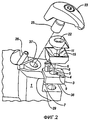
фиг.2 представляет собой вид изобретения с пространственным разделением деталей, рассчитанного на охлаждение только передней и задней поверхности режущей пластины;figure 2 is a view of the invention with a spatial separation of parts, designed to cool only the front and rear surfaces of the cutting insert;
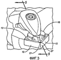
фиг.3 представляет собой вид изобретения в перспективе с соплами, рассчитанного на охлаждение передней поверхности режущей пластины;figure 3 is a perspective view of the invention with nozzles, designed to cool the front surface of the cutting insert;
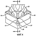
фиг.4 представляет собой вид в перспективе предпочтительного варианта осуществления изобретения с соплами, рассчитанного на охлаждение большим объемом текучей среды передней и задней поверхности режущей пластины;Fig. 4 is a perspective view of a preferred embodiment of the invention with nozzles designed to cool a large volume of fluid of the front and rear surfaces of the cutting insert;
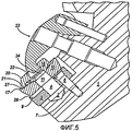
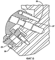
фиг.5 представляет собой поперечное сечение вида в перспективе изобретения, рассчитанного на охлаждение передней и задней поверхности режущей пластины;5 is a cross-sectional perspective view of an invention designed to cool the front and rear surfaces of a cutting insert;
фиг.6 представляет собой поперечное сечение вида в перспективе изобретения, рассчитанного на охлаждение передней поверхности и охлаждение большим объемом текучей среды задней поверхности режущей пластины;Fig.6 is a cross section of a perspective view of the invention, designed for cooling the front surface and cooling a large volume of fluid back surface of the cutting insert;
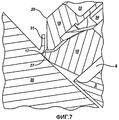
фиг.7 представляет собой поперечное сечение вида в перспективе изобретения, обрабатывающего заготовку и формирующего стружку;Fig.7 is a cross section of a perspective view of the invention, processing the workpiece and forming chips;
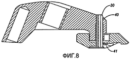
фиг.8 представляет собой поперечное сечение вида в перспективе фиксатора и верхнего элемента, которые закреплены вместе с помощью разрезного пружинного фиксатора;Fig. 8 is a cross-sectional perspective view of a latch and an upper member that are secured together with a split spring lock;
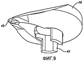
фиг.9 представляет собой вид стороны режущей пластины верхнего элемента с центрирующим штифтом; иFig.9 is a side view of the cutting insert of the upper element with a centering pin; and
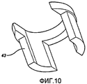
фиг.10 представляет собой вид в перспективе центрирующего штифта.10 is a perspective view of a centering pin.
Описание предпочтительного варианта осуществления изобретенияDescription of a preferred embodiment of the invention
Если обратиться к фиг.1 изобретения, то видно, что державка 1 резца имеет углубление 29 для размещения режущей пластины 10. Державка 1 резца также имеет канал 2 для подачи охлаждающей текучей среды в углубление 29. Индексируемая режущая пластина 10 расположена в углублении 29. Режущая пластина 10 содержит, по меньшей мере, одну заднюю поверхность 12, переднюю поверхность 13 и нижнюю поверхность 14. Линия пересечения задней поверхности 12 и передней поверхности 13 образует режущую кромку 16. В случае наличия множества боковых поверхностей линия пересечения между двумя смежными задними поверхностями 12 и передней поверхностью 13 образуют режущий угол 17. Следует отметить, что у круглой режущей пластины отсутствуют две смежные задние поверхности и, следовательно, нет режущего угла. Невзирая на отсутствие у круглой режущей пластины режущего угла, следует отметить, что в любом случае у нее присутствует режущая кромка. Выемка 15 режущей пластины расположена в передней поверхности 13 режущей пластины 10. Выемка 15 режущей пластины представляет собой область в передней поверхности 13, которая расположена ниже остальной части передней поверхности 13, окружающей выемку 15 режущей пластины и имеющую режущие кромки 16 и соответственно режущий угол 17. В одном из вариантов осуществления изобретения режущие кромки 16 и режущий угол расположены в одной и той же плоскости. Очевидно, что некоторые из режущих кромок могут также располагаться по вертикали выше или ниже друг друга. Например, такое должно произойти, если в качестве режущей пластины для металлорежущей системы была бы использована режущая пластина в форме эллипса с неровной верхней поверхностью.Referring to FIG. 1 of the invention, it is seen that the
Режущая пластина 10 имеет отверстие 11, выровненное с каналом 2 для подачи охлаждающей текучей среды державки 1 резца для подачи охлаждающей текучей среды. Отверстие 11 режущей пластины 11 открыто как в сторону ее передней поверхности 13, так и в сторону ее задней поверхности 14. Верхний элемент 18 примыкает к режущей пластине 10. Верхний элемент 18 имеет сторона 20 фиксатора и сторона 19 режущей пластины. Сторона 19 режущей пластины верхнего элемента 18 имеет форму, которая соответствует выемке 15 режущей пластины, так что их совместное позиционирование образует уплотнение. Верхний элемент также имеет емкость 34 (показана на фиг.5), расположенную на стороне 19 режущей пластины. Емкость 34 представляет собой гнездо на стороне 19 режущей пластины верхнего элемента 18, которая выровнена с отверстием 11 режущей пластины. Емкость 34 подает охлаждающую текучую среду к верхнему элементу 18. Верхний элемент 18 также имеет, по меньшей мере, один канал 21 охлаждения передней поверхности. Канал 21 охлаждения передней поверхности представляет собой канавку, выполненную на стороне 19 режущей пластины верхнего элемента 18, проходящую от емкости 34 к точке на верхнем элементе 18, ближайшей к режущей кромке 16 или режущему углу 17 соответственно. Обратитесь к фиг.5 для рассмотрения канала 21 охлаждения передней поверхности. Когда верхний элемент 18 попадает в выемку 15 режущей пластины, канал 21 охлаждения передней поверхности плотно прилегает к выемке 15 режущей пластины для образования прохода для подачи охлаждающей текучей среды на режущую кромку 16 или на режущий угол 17. Также предполагается, что канал 21 охлаждения передней поверхности, можно было бы образовать посредством канавки в выемке 15 режущей пластины, которая плотно прилегает к стороне режущей пластины 19 в составе верхнего элемента 18. Фиксатор 23 оказывает давление на выемку 22 верхнего элемента. Фиксатор 23 сохраняет выравнивание и уплотнение между верхним элементом 18, режущей пластиной 10 и державкой резца 1. Следует отметить, что тип используемого фиксатора 23 не ограничен тем, который показан на чертежах. Скорее всего фиксатор 23 может быть представлен любым иным подходящим типом, хорошо известным из уровня техники.The
Как показано на фиг.7, при взаимодействии режущей пластины 10 с рабочей заготовкой 30 стружка 31 на режущей кромке 16 или на режущем угле 17 удаляется с заготовки. Согласованное взаимное расположение верхнего элемента 18 и выемки 15 режущей пластины образует канал 21 охлаждения передней поверхности, который направляет охлаждающую текучую среду так, что она подается от угла ниже линии пересечения верхней поверхности 13 режущей пластины и стружки 31. Этот угол подачи способствует направлению охлаждающей текучей среды на нижнюю сторону стружки, что приводит к улучшению охлаждения и удалению стружки. Канал 21 охлаждения передней поверхности проходит от емкости 34 к точке, ближайшей к режущей кромке. Щель 27 первичного слива выполнена в конце канала 21 охлаждения передней поверхности вблизи режущей кромки 16 или режущего угла 17. Расположение щели 27 первичного слива ниже режущей кромки 16 или режущего угла 17 представляет собой важный аспект настоящего изобретения. В данном описании фразы «ниже режущей кромки» или «ниже режущего угла» обычно означает ориентацию в направлении углубления 29 в противоположность фразам «выше режущей кромки» или «выше режущего угла», что в общем случае означает ориентацию в направлении фиксатора. Охлаждение и удаление стружки происходит наиболее эффективно, когда щель первичного слива 27 располагается приблизительно в пределах 0,100 дюйма от стружки.As shown in Fig.7, when the cutting
В другом варианте осуществления изобретения, показанном на фиг.2 и фиг.5, регулировочная прокладка 3, имеющая верхнюю сторону 8 и нижнюю сторону 36, располагается между державкой резца 1 и режущей пластиной 10. Регулировочная прокладка 3 ориентирована таким образом, чтобы ее нижняя сторона 36 примыкала к державке резца 1, а ее верхняя сторона - к режущей пластине 10. Штифт 6 регулировочной прокладки 6 вставлен в отверстие 5 для штифта регулировочной прокладки и отверстие 7 для штифта державки резца. Штифт 6 регулировочной прокладки сохраняет выравнивание регулировочной прокладки 3 между державкой резца 1 и режущей пластиной 10. Отверстие 4 регулировочной прокладки выполнено в центре регулировочной прокладки 3. Отверстие 4 регулировочной прокладки обеспечивает проход для охлаждающей текучей среды от канала 2 для подачи охлаждающей текучей среды державки 1 резца до отверстия 11 режущей пластины. Щель, образующая часть канала 9 охлаждения задней поверхности, предусмотрена на верхней стороне 8 регулировочной прокладки 3. Для образования канала 9 охлаждения задней поверхности нижняя поверхность 14 режущей пластины закрывает открытую щель на верхней стороне 8 регулировочной прокладки 3. Канал 9 охлаждения задней поверхности проходит от отверстия 4 регулировочной прокладки почти до ее наружной части, которая находится ближе всего к режущей кромке 16 или к режущему углу 17. Конец канала 9 охлаждения задней поверхности, который расположен ближе всего к режущей кромке, имеет криволинейное основание, так что охлаждающая текучая среда направляется прямо к режущей кромке 16 или к режущему углу 17 либо к задней поверхности 12 режущей пластины 10.In another embodiment of the invention shown in FIG. 2 and FIG. 5, an
Как показано в варианте осуществления изобретения, режущая пластина 10 имеет задние поверхности 12 и боковые кромки 32, которые скошены внутрь под пологим углом от передней поверхности 13 к нижней поверхности 14. Таким образом ширина регулировочной прокладки 3 станет меньше ширины нижней поверхности 14 и ширины передней поверхности 13. Следует отметить, что такой уклон предназначен для того, чтобы подвергнуть задние поверхности 12 и боковую кромку 16 воздействию охлаждающей текучей среды. Скашивание режущей пластины 10 позволяет открыть часть канала 9 охлаждения задней поверхности для образования отверстия 28 вторичного слива, в результате чего становится возможным выталкивание охлаждающей текучей среды вдоль задних поверхностей режущей пластины 10.As shown in an embodiment of the invention, the cutting
В третьем варианте осуществления изобретения, показанном на фиг.3, верхний элемент 18 имеет сопла 33. Сопла 33 являются дополнительными каналами для подачи охлаждающей текучей среды для увеличения скорости ее потока и эффективного направления большего количества текучей среды в зону контакта между резцом и стружкой. Сопла 33 проходят от емкости 34 к точке слива, расположенной на стороне 20 фиксатора верхнего элемента 18, от которой охлаждающая текучая среда может быть направлена в зону контакта между резцом и стружкой.In the third embodiment of the invention shown in FIG. 3, the
Альтернативный вариант осуществления изобретения показан на фиг.4 и фиг.6. В этом варианте осуществления изобретения самая высокая скорость подачи охлаждающей текучей среды достигается при охлаждении передней и задней поверхности режущей пластины. В этом узле регулировочная прокладка 3 установлена в углублении 29 державки 1 резца, в которой выполнено отверстие 7 для штифта. В регулировочной прокладке 3 выполнено отверстие 4 и отверстие 5 для штифта. Штифт 6 регулировочной прокладки имеет резьбу и проходит через отверстие 5 для штифта регулировочной прокладки в отверстие 7 для штифта державки резца, которое также имеет резьбу. Такая конструкция сохраняет выравнивание регулировочной прокладки 3 с углублением 29. Между державкой 1 резца и регулировочной прокладкой 3 выполнен канал 35 охлаждения задней поверхности большим количеством текучей среды. Часть этого канала 35 охлаждения задней поверхности большим количеством текучей среды образована канавкой, расположенной на нижней стороне 36 регулировочной прокладки 3. Эта канавка также могла быть выполнена в углублении 29 державки 1 резца. Канавка закрывается углублением 29 державки 1 резца, создавая при этом канал для подачи охлаждающей текучей среды. Канал 35 охлаждения задней поверхности большим количеством текучей среды частично проходит вдоль контактной зоны между державкой 1 резца и регулировочной прокладкой 3, начинаясь от отверстия 4 регулировочной прокладки, затем он проходит через корпус регулировочной прокладки 3 к задней поверхности 12 или боковой кромке 32 режущей пластины 10 и заканчивается отверстием 28 вторичного слива на углу регулировочной прокладки 3 вблизи режущей кромки 16 или режущего угла 17 режущей пластины 10.An alternative embodiment of the invention is shown in FIG. 4 and FIG. 6. In this embodiment, the highest flow rate of the cooling fluid is achieved by cooling the front and rear surfaces of the insert. In this node, the adjusting
Для обеспечения возможности достаточного смыва охлаждающей текучей средой, поступающей из отверстия 28 вторичного слива, режущая пластина 10 имеет скошенные задние поверхности 12 и боковые кромки 32. Отверстие 11 режущей пластины выравнивается с отверстием 4 регулировочной прокладки. Для формирования плотного гидравлического затвора нижняя поверхность 14 режущей пластины упирается в регулировочную прокладку 3. Выемке 15 режущей пластины 10 придана форма усеченного конуса, которая для формирования плотного гидравлического затвора соответствует стороне 19 режущей пластины верхнего элемента 18. Стороне 19 режущей пластины верхнего элемента 18 также придана форма усеченного конуса. Емкость расположена в центральной части стороны 19 режущей пластины и выровнена с отверстием 11 режущей пластины. Выравнивание емкости 11, отверстия 11 режущей пластины, отверстия 4 регулировочной прокладке и канала 2 для подачи охлаждающей текучей среды создает камеру, из которой охлаждающая текучая среда может свободно вытекать в канал 35 охлаждения задней поверхности большим количеством текучей среды, канал 21 охлаждения передней поверхности и в сопла 33. В предпочтительном варианте осуществления изобретения канал охлаждения 21 передней поверхности проходит от емкости 34 в пределах приблизительно 0,100 дюймов от режущей кромки 16 или режущего угла 17. В конце канала 21 охлаждения передней поверхности напротив емкости 34 расположен выступ 42, расположенный на стороне 19 режущей пластины верхнего элемента 18. Выступ 42 представляет собой выпуклость, которая выступает от той стороны режущей пластины, которая пересекается с потоком охлаждающей текучей среды по мере ее выхода из щели 27 первичного слива. Вид выступа 42 наиболее отчетливо показан на фиг.9. Выступ 42 вызывает разбрызгивание охлаждающей текучей среды, поступающей из щели 27 первичного слива 27, на большое расстояние вширь, что совершенно непохоже на ее менее желательный сконцентрированный поток, которым она протекает в случае отсутствия выступа 42. Канал охлаждения передней поверхности выполнен в виде достаточно широкого канала для увеличения до максимума потока охлаждающей текучей среды, направляемой так, чтобы стружки не попадали в канал. Два сопла 33 проходят от емкости 34 до точек выхода на стороне 20 фиксатора, которые направят охлаждающую текучую среду к режущей кромке 16 или к режущему углу 17. Выемка 22 верхнего элемента расположена на стороне 20 фиксатора. Для установки режущей пластины 10 и сохранения плотного гидравлического затвора во всех каналах прохождения охлаждающей текучей среды фиксатор 23 снабжен головкой 24, которая взаимодействует с выемкой 22 верхнего элемента. В предпочтительном варианте осуществления изобретения винт 25 фиксатора оказывает давление на его головку 24 в направлении верхнего элемента 18. Штифт 26 фиксатора сохраняет выравнивание головки 24 фиксатора. Следует отметить, что хотя на фиг.1-6 и 8 и показан конкретный узел фиксатора, будет вполне достаточным применение любого подходящего узла фиксатора, который в состоянии надежно удерживать верхний элемент, режущую пластину 10 и регулировочную прокладку 3 в углублении 29. Многие из этих узлов фиксации имеются в продаже и хорошо известны специалистам в данной области техники.To ensure that sufficient cooling fluid can be flushed out of the
В предпочтительном варианте осуществления изобретения общий поток охлаждающей текучей среды во всех каналах для подачи охлаждающей текучей среды не должен превышать 80% от возможного потока, поступающего из канала для текучей среды, для которого не предусмотрено ограничение подачи текучей среды.In a preferred embodiment of the invention, the total flow of cooling fluid in all channels for supplying a cooling fluid should not exceed 80% of the possible flow coming from a channel for a fluid for which there is no restriction in the flow of fluid.
Следует отметить, что в случае прикрепления верхнего элемента 18 к фиксатору 23 были отмечены некоторые преимущества, связанные с обслуживанием оборудования. Такая конструкция снижает вероятность того, что оператор непреднамеренно уронит верхний элемент во время снятия или установки узла. Наиболее эффективным средством прикрепления верхнего элемента 18 к фиксатору 23 является разрезной пружинный штифт 39. Разрезной пружинный штифт 39 вставляется в рассверленное отверстие 40 фиксатора и в рассверленное отверстие 41 верхнего элемента, которые выровнены как показано на фиг.8. Хотя возможно применение и других средств совместного соединения элементов, использование разрезного пружинного штифта 39 обеспечивает некоторое вращение верхнего элемента 18 вокруг основной оси разрезного пружинного штифта 39. Такая конструкция позволяет выровнять верхний элемент 18 при различных ориентациях режущей пластины 10.It should be noted that in the case of attaching the
Центрирующий штифт 43 может быть установлен между верхним элементом 18 и режущей пластиной 10. Центрирующий штифт 43 устанавливается на емкости 34 и проходит в отверстие 11 режущей пластины. Форма центрирующего штифта соответствует границам емкости 34 и отверстию 11 режущей пластины, и таким образом, центрирующий штифт 43 действует как выравнивающее приспособление. У центрирующего штифта имеется открытая внутренняя часть, так что поступление потока охлаждающей текучей среды не ограничивается. На фиг.9 показан центрирующий штифт, прикрепленный к емкости 34 верхнего элемента 18, а на фиг.10 - отдельный вид центрирующего штифта. Для иллюстрации режущая пластина 10 не показана на фиг.9.A centering
Документы, патенты и заявки на патенты, упоминаемые здесь, включены сюда посредством ссылки.The documents, patents, and patent applications referred to herein are hereby incorporated by reference.
В то время как было приведено описание изобретения в связи с его конкретными вариантами осуществления, следует понимать, что оно приведено лишь для иллюстрации, а не для ограничения, и объем приложенной формулы изобретения следует интерпретировать настолько широко, насколько это позволит предшествующий уровень техники.While the invention has been described in connection with its specific embodiments, it should be understood that it is provided for illustration only and not limitation, and the scope of the appended claims should be interpreted as broadly as the prior art allows.
Claims (28)
державку резца, имеющую углубление и канал для подачи охлаждающей текучей среды,
режущую пластину, установленную в углублении, при этом режущая пластина содержит, по меньшей мере, одну режущую кромку и переднюю поверхность, причем режущая пластина имеет выемку, которая расположена ниже остальной части передней поверхности и, по меньшей мере, одной режущей кромки,
верхний элемент, содержащий сторону, обращенную к фиксатору, и сторону, обращенную к режущей пластине, которая имеет соответствующую форму для совпадения с выемкой режущей пластины и совместного образования с ней канала охлаждения между верхним элементом и выемкой режущей пластины для подачи текучей среды к, по меньшей мере, одной режущей кромке, и
фиксатор для надежного удержания верхнего элемента и режущей пластины относительно державки резца,
при этом канал охлаждения сообщен с каналом для подачи охлаждающей текучей среды и щелью первичного слива, для подачи охлаждающей текучей среды к режущей кромке, причем щель первичного слива расположена ниже, по меньшей мере, одной режущей кромки.1. A metal cutting system containing
a tool holder having a recess and a channel for supplying a cooling fluid,
a cutting insert mounted in the recess, wherein the cutting insert comprises at least one cutting edge and a front surface, the cutting plate having a recess that is located below the rest of the front surface and at least one cutting edge,
an upper element comprising a side facing the latch and a side facing the cutting insert, which has a corresponding shape to coincide with the notch of the cutting insert and jointly forming a cooling channel with it between the upper element and the notch of the cutting insert for supplying fluid to at least at least one cutting edge, and
a clamp for securely holding the upper element and the cutting insert relative to the tool holder,
wherein the cooling channel is in communication with the channel for supplying the cooling fluid and the primary discharge slot, for supplying the cooling fluid to the cutting edge, the primary discharge slot being located below at least one cutting edge.
державку резца, имеющую углубление и канал для подачи текучей среды,
регулировочную прокладку, нижняя сторона которой примыкает к державке резца в углублении, а верхняя сторона расположена напротив нижней стороны, и содержащую отверстие, выровненное с каналом для подачи охлаждающей текучей среды и проходящее от нижней стороны к верхней стороне,
режущую пластину, имеющую переднюю поверхность, нижнюю поверхность, заднюю поверхность и боковую кромку, при этом задняя поверхность скошена, и боковая кромка скошена в том же направлении, что задняя поверхность, причем нижняя поверхность режущей пластины расположена на верхней стороне регулировочной прокладки,
канал охлаждения задней поверхности, выполненный между регулировочной прокладкой и режущей пластиной и заканчивающийся отверстием вторичного слива, направленным на режущую кромку или заднюю поверхность, при этом канал охлаждения задней поверхности сообщен с каналом для подачи охлаждающей текучей среды, и
фиксатор для надежного удержания режущей пластины и регулировочной прокладки в державке резца.7. A metal cutting system containing
a tool holder having a recess and a channel for supplying fluid,
an adjustment gasket, the lower side of which is adjacent to the tool holder in the recess, and the upper side is opposite the lower side, and containing a hole aligned with the channel for supplying cooling fluid and passing from the lower side to the upper side,
a cutting insert having a front surface, a lower surface, a rear surface and a side edge, wherein the rear surface is beveled and the side edge is beveled in the same direction as the rear surface, the lower surface of the cutting plate being located on the upper side of the shim,
a cooling surface of the rear surface, made between the adjusting gasket and the cutting insert and ending with a secondary drain hole directed to the cutting edge or rear surface, while the cooling surface of the rear surface is in communication with the channel for supplying cooling fluid, and
retainer for secure holding of the insert and shim in the tool holder.
державку резца, имеющую углубление и канал для подачи охлаждающей текучей среды,
регулировочную прокладку, нижняя сторона которой примыкает к державке резца в углублении, а верхняя сторона расположена напротив нижней стороны, и содержащую отверстие, выровненное с каналом для подачи охлаждающей текучей среды и проходящее от нижней стороны к верхней стороне,
режущую пластину, имеющую переднюю поверхность, нижнюю поверхность, по меньшей мере, одну скошенную заднюю поверхность и, по меньшей мере, один режущий угол, скошенный в том же направлении, что и задняя поверхность, при этом нижняя поверхность расположена на верхней стороне регулировочной прокладки,
канал охлаждения задней поверхности, изначально выполненный между регулировочной прокладкой и державкой резца и частично проходящий через регулировочную прокладку, в результате чего канал охлаждения задней поверхности заканчивается отверстием вторичного слива, направленным на режущую кромку или заднюю поверхность, при этом канал охлаждения задней поверхности сообщен с каналом для подачи охлаждающей текучей среды державки резца, и
фиксатор для надежного удержания режущей пластины и регулировочной прокладки в державке резца.11. A metal cutting system containing
a tool holder having a recess and a channel for supplying a cooling fluid,
an adjustment gasket, the lower side of which is adjacent to the tool holder in the recess, and the upper side is opposite the lower side, and containing a hole aligned with the channel for supplying cooling fluid and passing from the lower side to the upper side,
a cutting insert having a front surface, a lower surface, at least one beveled rear surface and at least one cutting angle beveled in the same direction as the rear surface, the lower surface being located on the upper side of the shim,
the cooling surface of the rear surface, originally made between the adjustment gasket and the tool holder and partially passing through the adjustment gasket, as a result of which the cooling channel of the rear surface ends with a secondary drain hole directed to the cutting edge or rear surface, while the cooling channel of the rear surface is in communication with the channel for supplying cooling fluid to the tool holder, and
retainer for secure holding of the insert and shim in the tool holder.
державку резца, имеющую углубление и канал для подачи охлаждающей текучей среды,
регулировочную прокладку, нижняя сторона которой примыкает к державке резца в углублении, а верхняя сторона расположена напротив нижней стороны, и содержащую отверстие, выровненное с каналом для подачи охлаждающей текучей среды и проходящее от нижней стороны к верхней стороне,
режущую пластину, имеющую переднюю поверхность с выемкой, расположенной ниже остальной части передней поверхности, по меньшей мере, две кромки, пересекающихся с образованием, по меньшей мере, одного режущего угла, нижнюю поверхность, по меньшей мере, одну скошенную заднюю поверхность, по меньшей мере, одну боковую кромку, скошенную в том же направлении, что задняя поверхность, и отверстие, проходящее от нижней поверхности к передней поверхности режущей пластины, при этом нижняя поверхность расположена на верхней стороне регулировочной прокладки,
канал охлаждения задней поверхности, выполненный между регулировочной прокладкой и режущей пластиной и заканчивающийся отверстием вторичного слива, направленным на режущую кромку или заднюю поверхность, причем канал охлаждения задней поверхности сообщен с каналом для подачи охлаждающей текучей среды,
верхний элемент, содержащий сторону, обращенную к фиксатору, и сторону, обращенную к режущей пластине, которая имеет соответствующую форму для совпадения с выемкой режущей пластины и совместного образования с ней канала охлаждения между верхним элементом и выемкой режущей пластины для подачи охлаждающей текучей среды к режущему углу или режущей кромке, при этом канал охлаждения сообщается с каналом для подачи охлаждающей текучей среды и щелью первичного слива, для подачи охлаждающей текучей среды к режущему углу, причем щель первичного слива расположена ниже, по меньшей мере, одного режущего угла, и
фиксатор для надежного удержания режущей пластины и регулировочной прокладки в державке резца.13. A metal cutting system containing
a tool holder having a recess and a channel for supplying a cooling fluid,
an adjustment gasket, the lower side of which is adjacent to the tool holder in the recess, and the upper side is opposite the lower side, and containing a hole aligned with the channel for supplying cooling fluid and passing from the lower side to the upper side,
a cutting insert having a front surface with a recess located below the rest of the front surface, at least two edges intersecting to form at least one cutting angle, the lower surface, at least one beveled rear surface, at least , one side edge, beveled in the same direction as the rear surface, and a hole extending from the lower surface to the front surface of the cutting insert, while the lower surface is located on the upper side of the adjustment masonry,
a cooling surface of the rear surface, made between the adjusting gasket and the cutting insert and ending with a secondary drain hole directed to the cutting edge or rear surface, and the cooling channel of the rear surface is in communication with the channel for supplying cooling fluid,
the upper element containing the side facing the latch and the side facing the cutting insert, which has a corresponding shape to coincide with the notch of the cutting insert and the joint formation of a cooling channel between the upper element and the notch of the cutting plate for supplying cooling fluid to the cutting corner or a cutting edge, wherein the cooling channel communicates with the channel for supplying the cooling fluid and the primary discharge slot, for supplying the cooling fluid to the cutting corner, the primary gap the drain is located below at least one cutting angle, and
retainer for secure holding of the insert and shim in the tool holder.
державку резца, имеющую углубление и канал для подачи охлаждающей текучей среды,
регулировочную прокладку, нижняя сторона которой примыкает к державке резца в углублении, а верхняя сторона расположена напротив нижней стороны, и содержащую отверстие, выровненное с каналом для подачи охлаждающей текучей среды и проходящее от нижней стороны к верхней стороне,
режущую пластину, имеющую переднюю поверхность с выемкой, расположенной ниже остальной части передней поверхности, по меньшей мере, одну режущую кромку, нижнюю поверхность, по меньшей мере, одну скошенную заднюю поверхность, по меньшей мере, одну боковую кромку, скошенную в том же направлении, что задняя поверхность, и отверстие, проходящее от нижней поверхности к передней поверхности, при этом нижняя поверхность расположена на верхней стороне регулировочной прокладки, канал охлаждения задней поверхности, изначально выполненный между регулировочной прокладкой и державкой резца и частично проходящий через регулировочную прокладку, в результате чего канал охлаждения задней поверхности заканчивается отверстием вторичного слива, направленным на режущую кромку или заднюю поверхность, причем канал охлаждения задней поверхности сообщен с каналом для подачи охлаждающей текучей державки резца для подачи текучей среды на заднюю поверхность,
верхний элемент, содержащий сторону, обращенную к фиксатору, и сторону, обращенную к режущей пластине, которая имеет соответствующую форму для совпадения с выемкой режущей пластины и совместного образования с ней канала охлаждения между верхним элементом и выемкой режущей пластины для подачи текучей среды на режущий угол или режущую кромку, при этом канал охлаждения сообщается с каналом для подачи охлаждающей текучей среды и щелью первичного слива для подачи текучей среды к режущей кромке или режущему углу, причем щель первичного слива расположена ниже режущей кромки; и
фиксатор для надежного удержания верхнего элемента, режущей пластины и регулировочной прокладки в державке резца.21. A metal cutting system containing
a tool holder having a recess and a channel for supplying a cooling fluid,
an adjustment gasket, the lower side of which is adjacent to the tool holder in the recess, and the upper side is opposite the lower side, and containing a hole aligned with the channel for supplying cooling fluid and passing from the lower side to the upper side,
a cutting insert having a front surface with a recess located below the rest of the front surface, at least one cutting edge, a lower surface, at least one beveled rear surface, at least one side edge, beveled in the same direction, that the rear surface and the hole passing from the lower surface to the front surface, while the lower surface is located on the upper side of the shim, the cooling channel of the rear surface, originally made between with a gasket and a tool holder and partially passing through the adjustment gasket, as a result of which the cooling surface of the rear surface ends with a secondary drain hole directed to the cutting edge or rear surface, and the cooling channel of the rear surface is in communication with the channel for supplying the cutting fluid holder of the tool for supplying fluid on the back surface
an upper element comprising a side facing the latch and a side facing the cutting insert, which has a corresponding shape to coincide with the notch of the cutting insert and jointly forming a cooling channel with it between the upper element and the notch of the cutting plate to supply fluid to the cutting angle or the cutting edge, while the cooling channel is in communication with the channel for supplying the cooling fluid and the primary discharge slot for supplying fluid to the cutting edge or cutting angle, and the primary discharge gap located below the cutting edge; and
retainer for securely holding the upper element, cutting insert and shim in the tool holder.
Applications Claiming Priority (2)
| Application Number | Priority Date | Filing Date | Title |
|---|---|---|---|
| US11/654,918 US7883299B2 (en) | 2007-01-18 | 2007-01-18 | Metal cutting system for effective coolant delivery |
| US11/654,918 | 2007-01-18 |
Publications (2)
| Publication Number | Publication Date |
|---|---|
| RU2009131308A RU2009131308A (en) | 2011-02-27 |
| RU2445189C2 true RU2445189C2 (en) | 2012-03-20 |
Family
ID=39636274
Family Applications (1)
| Application Number | Title | Priority Date | Filing Date |
|---|---|---|---|
| RU2009131308/02A RU2445189C2 (en) | 2007-01-18 | 2007-12-12 | Metal cutting system with efficient feed of coolant |
Country Status (8)
| Country | Link |
|---|---|
| US (8) | US7883299B2 (en) |
| EP (1) | EP2104610A4 (en) |
| JP (1) | JP2010516482A (en) |
| CN (1) | CN101600569B (en) |
| BR (1) | BRPI0721033A2 (en) |
| CA (1) | CA2674930A1 (en) |
| RU (1) | RU2445189C2 (en) |
| WO (1) | WO2008088627A1 (en) |
Cited By (3)
| Publication number | Priority date | Publication date | Assignee | Title |
|---|---|---|---|---|
| RU2598138C1 (en) * | 2015-06-22 | 2016-09-20 | Нина Алексеевна Корюкина | Tangential cutting plate and cutter |
| RU2611184C2 (en) * | 2015-07-24 | 2017-02-21 | Нина Алексеевна Корюкина | Circular cutting plate and modular cutter |
| RU179894U1 (en) * | 2017-05-31 | 2018-05-28 | ОАО "Свердловский инструментальный завод" | CUTTER |
Families Citing this family (49)
| Publication number | Priority date | Publication date | Assignee | Title |
|---|---|---|---|---|
| US7625157B2 (en) * | 2007-01-18 | 2009-12-01 | Kennametal Inc. | Milling cutter and milling insert with coolant delivery |
| US8439608B2 (en) | 2007-01-18 | 2013-05-14 | Kennametal Inc. | Shim for a cutting insert and cutting insert-shim assembly with internal coolant delivery |
| US8727673B2 (en) | 2007-01-18 | 2014-05-20 | Kennametal Inc. | Cutting insert with internal coolant delivery and surface feature for enhanced coolant flow |
| US8328471B2 (en) | 2007-01-18 | 2012-12-11 | Kennametal Inc. | Cutting insert with internal coolant delivery and cutting assembly using the same |
| US9101985B2 (en) * | 2007-01-18 | 2015-08-11 | Kennametal Inc. | Cutting insert assembly and components thereof |
| US8454274B2 (en) | 2007-01-18 | 2013-06-04 | Kennametal Inc. | Cutting inserts |
| US7883299B2 (en) | 2007-01-18 | 2011-02-08 | Kennametal Inc. | Metal cutting system for effective coolant delivery |
| US7963729B2 (en) | 2007-01-18 | 2011-06-21 | Kennametal Inc. | Milling cutter and milling insert with coolant delivery |
| US20080175679A1 (en) * | 2007-01-18 | 2008-07-24 | Paul Dehnhardt Prichard | Milling cutter and milling insert with core and coolant delivery |
| US7955032B2 (en) * | 2009-01-06 | 2011-06-07 | Kennametal Inc. | Cutting insert with coolant delivery and method of making the cutting insert |
| SE0950092A1 (en) * | 2009-02-20 | 2010-06-08 | Seco Tools Ab | Cutting tools and cutters with fluid flow structures |
| IL206283A0 (en) | 2010-06-10 | 2010-11-30 | Iscar Ltd | Cutting tool and nozzle therefor |
| US8827599B2 (en) | 2010-09-02 | 2014-09-09 | Kennametal Inc. | Cutting insert assembly and components thereof |
| US8734062B2 (en) | 2010-09-02 | 2014-05-27 | Kennametal Inc. | Cutting insert assembly and components thereof |
| US8596935B2 (en) | 2010-10-08 | 2013-12-03 | TDY Industries, LLC | Cutting tools and cutting inserts including internal cooling |
| US9180650B2 (en) | 2010-10-08 | 2015-11-10 | Kennametal Inc. | Cutting tool including an internal coolant system and fastener for a cutting tool including an internal coolant system |
| RU2604547C2 (en) * | 2010-11-24 | 2016-12-10 | Ноу Скрю Лтд. | Cutting tool with cooling mechanism, as well as cutting insert and tool holder |
| DE102011016148B4 (en) | 2011-03-28 | 2024-06-06 | Hartmetall-Werkzeugfabrik Paul Horn Gmbh | Tool for machining a workpiece with lateral coolant outlet and holder for the tool |
| US9486141B2 (en) | 2011-08-09 | 2016-11-08 | Carestream Health, Inc. | Identification of dental caries in live video images |
| DE102011080701A1 (en) * | 2011-08-09 | 2013-02-14 | Komet Group Gmbh | Tool head for a machine tool |
| DE102011053772B3 (en) * | 2011-09-20 | 2013-02-21 | Optotech Optikmaschinen Gmbh | Method and device for processing a plastic part with a lathe device |
| US8827598B2 (en) * | 2011-11-22 | 2014-09-09 | Kennametal Inc. | Cutting assembly with enhanced coolant delivery |
| US8826786B2 (en) * | 2012-02-23 | 2014-09-09 | Iscar, Ltd. | Cutting tool with internal fluid delivery system |
| US20140249256A1 (en) * | 2012-06-26 | 2014-09-04 | Homax Products, Inc. | Texture Material for Covering a Repaired Portion of a Textured Surface |
| JP6006588B2 (en) * | 2012-09-04 | 2016-10-12 | 日本特殊陶業株式会社 | Cutting tool holder and cutting tool |
| DE102013111771A1 (en) * | 2012-10-31 | 2014-04-30 | Kennametal Inc. | Cutting insert assembly for use during chip forming removal of material from insert-chip interface, has locking pin with pin bore opening to boss bore of plate, so that coolant flows into boss bore and to interior passage of plate |
| US8985913B2 (en) * | 2012-11-13 | 2015-03-24 | Iscar, Ltd. | Cutting tool holder with internal coolant passage having a compressible member |
| JP6122341B2 (en) * | 2013-05-28 | 2017-04-26 | 京セラ株式会社 | CUTTING TOOL AND PROCESS FOR PRODUCING CUT WORK |
| US9511421B2 (en) | 2013-06-14 | 2016-12-06 | Kennametal Inc. | Cutting tool assembly having clamp assembly comprising a clamp and a coolant plate |
| JP6225593B2 (en) * | 2013-09-19 | 2017-11-08 | 株式会社ジェイテクト | Sim breaker |
| JP6314636B2 (en) * | 2014-05-08 | 2018-04-25 | 株式会社デンソー | Cutting device |
| EP2946857B1 (en) * | 2014-05-19 | 2019-10-16 | Sandvik Intellectual Property AB | Turning tool holder and cutting tool insert |
| US9586263B2 (en) | 2014-06-05 | 2017-03-07 | Kennametal Inc | Tool holder having improved internal coolant delivery |
| JP6446876B2 (en) * | 2014-07-15 | 2019-01-09 | 株式会社ジェイテクト | Cutting tool |
| US10471219B2 (en) * | 2014-11-24 | 2019-11-12 | Sanofi | Drug delivery device with variable piston force |
| CN104923813A (en) * | 2015-06-24 | 2015-09-23 | 昆山市优科精密工具有限公司 | Tool device with automatic chip removal and breaking function |
| SE540533C2 (en) * | 2016-02-12 | 2018-09-25 | Plasmatrix Mat Ab | Cutting tool assembly with controlled resilience using hyperelastic materials |
| JP2018027605A (en) * | 2016-08-19 | 2018-02-22 | 住友電工ハードメタル株式会社 | Plank for cutting tool, and cutting tool |
| CN106984840A (en) * | 2017-05-19 | 2017-07-28 | 哈尔滨理工大学 | A kind of sub-cooled lubricates special interior cold lathe tool |
| KR20200020867A (en) * | 2017-07-27 | 2020-02-26 | 스미또모 덴꼬오 하드메탈 가부시끼가이샤 | Holder for cutting tool |
| JP6651136B2 (en) * | 2017-10-25 | 2020-02-19 | 株式会社タンガロイ | Cutting inserts, deposits and holders |
| JP7335645B2 (en) * | 2017-11-30 | 2023-08-30 | 株式会社NejiLaw | Cutting tool and blade holder |
| JP7051067B2 (en) * | 2017-11-30 | 2022-04-11 | 株式会社NejiLaw | Cutting tools and blade holders |
| EP3539696B1 (en) * | 2018-03-13 | 2023-10-11 | AB Sandvik Coromant | Turning tool for metal cutting comprising a coolant channel |
| AT16570U1 (en) * | 2018-08-01 | 2020-01-15 | Ceratizit Austria Gmbh | Rotary tool holder |
| CN109332775B (en) * | 2018-11-27 | 2020-05-05 | 株洲钻石切削刀具股份有限公司 | Inner-cooling three-edge milling cutter |
| EP3919211A1 (en) * | 2020-06-02 | 2021-12-08 | Ceratizit Luxembourg Sàrl | Milling tool, use thereof and milling process |
| CN115916436A (en) * | 2020-06-17 | 2023-04-04 | 住友电工硬质合金株式会社 | Coolant supply mechanism |
| JP7459451B1 (en) | 2023-10-06 | 2024-04-02 | 株式会社タンガロイ | Fixing member, tool body and cutting tool |
Citations (5)
| Publication number | Priority date | Publication date | Assignee | Title |
|---|---|---|---|---|
| SU560702A1 (en) * | 1975-01-13 | 1977-06-05 | Краматорский Индустриальный Институт | Cutter |
| SU902982A1 (en) * | 1979-04-04 | 1982-02-07 | Предприятие П/Я Г-4285 | Build-up cutting tool |
| EP0100376A2 (en) * | 1982-08-04 | 1984-02-15 | Rockwell International Corporation | Metal working tool |
| SU1230799A1 (en) * | 1984-03-22 | 1986-05-15 | Магнитогорский горно-металлургический институт им.Г.И.Носова | Internally cooled cutting tool |
| RU2036749C1 (en) * | 1992-11-23 | 1995-06-09 | Российский Университет Дружбы Народов | Cutting tool |
Family Cites Families (152)
| Publication number | Priority date | Publication date | Assignee | Title |
|---|---|---|---|---|
| US533520A (en) * | 1895-02-05 | Measuring-strap | ||
| US397114A (en) * | 1889-02-05 | dolsen | ||
| US348378A (en) * | 1886-08-31 | butlee | ||
| NL95590C (en) | 1952-12-31 | 1900-01-01 | ||
| US2870523A (en) * | 1956-08-10 | 1959-01-27 | Theophile J La Lime | Cutting tools |
| FR1279749A (en) | 1961-01-16 | 1961-12-22 | Cooling of cutting tools by a combination of two adjustable horizontal and vertical nozzles projecting a cooling lubricant under the chip | |
| US3429700A (en) | 1966-09-20 | 1969-02-25 | Teleflex Inc | Method of producing composite metal articles by uniting two identical shapes |
| US3323195A (en) | 1967-01-18 | 1967-06-06 | Scienco Inc | Coolant adapter for tool holder |
| US3486378A (en) | 1967-04-21 | 1969-12-30 | Gen Electric | Tool surface temperature measuring apparatus |
| US3571877A (en) | 1968-04-04 | 1971-03-23 | Neal P Jefferies | Cooling system for cutting tool and the like |
| US3971114A (en) | 1972-01-27 | 1976-07-27 | Dudley George M | Machine tool having internally routed cryogenic fluid for cooling interface between cutting edge of tool and workpiece |
| US3798726A (en) * | 1972-01-27 | 1974-03-26 | G Dudley | Metered coolant valve |
| US3889520A (en) * | 1973-02-13 | 1975-06-17 | Theodor Stoferle | Fluidic system for monitoring machine tool wear during a machining operation |
| FR2244590A1 (en) | 1973-09-20 | 1975-04-18 | Georges Jean Marie | Self-lubricating cutting tool for machine tool - has internal conduits press. feeding water-oil solution to root of cut |
| JPS50109295U (en) * | 1974-02-13 | 1975-09-06 | ||
| US4012061A (en) | 1974-12-23 | 1977-03-15 | Smith International, Inc. | Dual conduit drill stem member |
| SE417332B (en) | 1976-11-22 | 1981-03-09 | Uddeholms Ab | Tool steel |
| US4123194A (en) * | 1977-06-27 | 1978-10-31 | Pmc Industries, Inc. | Profiled chip breaker |
| US4204787A (en) | 1978-08-21 | 1980-05-27 | Kennametal Inc. | Milling cutter |
| SE429934B (en) | 1979-02-07 | 1983-10-10 | Sandvik Ab | CUTTING TOOL WITH BUILT-IN REFRIGERANT SUPPLY |
| JPS5933522Y2 (en) * | 1979-05-18 | 1984-09-19 | 東芝タンガロイ株式会社 | clamp bite |
| JPS603922B2 (en) | 1980-09-03 | 1985-01-31 | 日本油脂株式会社 | Cutting tools |
| USRE34180E (en) | 1981-03-27 | 1993-02-16 | Kennametal Inc. | Preferentially binder enriched cemented carbide bodies and method of manufacture |
| JPS59175903A (en) * | 1983-03-24 | 1984-10-05 | Toshiba Corp | Throwaway tip |
| US4535216A (en) * | 1983-10-14 | 1985-08-13 | Rockwell International Corporation | Metal-working tool using electrical heating |
| JPS60127904A (en) | 1983-12-13 | 1985-07-08 | Inoue Japax Res Inc | Cutting tool |
| US4579488A (en) * | 1984-02-21 | 1986-04-01 | Griffin James W | Boring bar assembly |
| US4682916A (en) | 1984-04-16 | 1987-07-28 | Briese Leonard A | Cutting insert arrangement |
| DE8424074U1 (en) * | 1984-08-14 | 1988-12-01 | MTU Motoren- und Turbinen-Union München GmbH, 8000 München | Tool holding device |
| US4880461A (en) | 1985-08-18 | 1989-11-14 | Hitachi Metals, Ltd. | Super hard high-speed tool steel |
| DE3601385A1 (en) | 1986-01-18 | 1987-07-23 | Krupp Gmbh | METHOD FOR PRODUCING SINTER BODIES WITH INNER CHANNELS, EXTRACTION TOOL FOR IMPLEMENTING THE METHOD, AND DRILLING TOOL |
| DE3715659A1 (en) | 1987-03-11 | 1988-09-22 | Guehring Gottlieb Fa | CLUTCH SYSTEM FOR CHIP LIFTING TOOLS |
| JPH0318083Y2 (en) * | 1987-03-25 | 1991-04-17 | ||
| US4880755A (en) | 1987-05-19 | 1989-11-14 | Kennametal Inc. | Sialon cutting tool composition |
| GB2209693B (en) | 1987-09-12 | 1991-04-24 | Multi Bar Systems Ltd | Tool holder adaptor. |
| DE3740814A1 (en) | 1987-12-02 | 1989-06-15 | Hertel Ag Werkzeuge Hartstoff | Clamping tool for cutting shaping |
| US4848198A (en) | 1988-04-21 | 1989-07-18 | Kennametal Inc. | Chip breaking tool holder |
| US5148728A (en) | 1988-09-12 | 1992-09-22 | The Curator Of The University Of Missouri | High pressure lubricooling machining of metals |
| SE467649B (en) | 1988-10-21 | 1992-08-24 | Sandvik Ab | SINTERATED DOUBLE POSITIVE SHALL CONSIST OF TWO IDENTICAL POWDER BODIES, AND METHOD FOR MANUFACTURING THE CUT |
| US5024976A (en) | 1988-11-03 | 1991-06-18 | Kennametal Inc. | Alumina-zirconia-silicon carbide-magnesia ceramic cutting tools |
| US4955264A (en) | 1989-05-30 | 1990-09-11 | Kennametal Inc. | Tool assembly with a hydraulic chip-breaking fluid system |
| SE9001409D0 (en) | 1990-04-20 | 1990-04-20 | Sandvik Ab | METHOD FOR MANUFACTURING OF CARBON METAL BODY FOR MOUNTAIN DRILLING TOOLS AND WEARING PARTS |
| US5388487A (en) | 1990-10-17 | 1995-02-14 | Sandvik Ab | Hydraulic tool holder with coolant jets |
| EP0483668B1 (en) | 1990-10-31 | 1996-03-13 | Hitachi Metals, Ltd. | High speed tool steel produced by sintering powder and method of producing same |
| ATE136480T1 (en) | 1991-03-13 | 1996-04-15 | Polytool Ag | REAMER WITH INTERCHANGEABLE CUTTING HEAD |
| IL97746A (en) * | 1991-04-02 | 1995-01-24 | Iscar Ltd | Metal cutting tool |
| IL99584A (en) | 1991-09-27 | 1996-08-04 | Iscar Ltd | Metal cutting tool |
| US5775854A (en) | 1991-09-27 | 1998-07-07 | Iscar Ltd. | Metal cutting tool |
| SE9103065D0 (en) | 1991-10-21 | 1991-10-21 | Sandvik Ab | METHOD FOR PREPARING CERAMIC BODY |
| US5237894A (en) | 1991-10-22 | 1993-08-24 | Cleveland State University | Material machining with improved fluid jet assistance |
| US5222843A (en) | 1992-06-22 | 1993-06-29 | Valenite Inc. | Insert for light feed, light depth of cut |
| US5288186A (en) | 1992-09-21 | 1994-02-22 | University Of Kentucky Research Foundation | Apparatus and method of high-pressure waterjet assisted cooling/lubrication in machining |
| US5290135A (en) | 1992-10-28 | 1994-03-01 | The Gleason Works | Rotary ring cutter having coolant distribution and discharge means |
| AT397626B (en) | 1992-11-20 | 1994-05-25 | Plansee Tizit Gmbh | CUTTING TOOL WITH INTEGRATED COOLANT FEED |
| US5265985A (en) | 1992-12-07 | 1993-11-30 | Valenite Inc. | Metal cutting insert |
| US5316323A (en) | 1993-01-08 | 1994-05-31 | Victor Jovanovic | Two-part tool holding fixture |
| US5382273A (en) | 1993-01-15 | 1995-01-17 | Kennametal Inc. | Silicon nitride ceramic and cutting tool made thereof |
| JP2602354Y2 (en) * | 1993-03-25 | 2000-01-11 | 京セラ株式会社 | Turning tool holder |
| DE4322409C2 (en) | 1993-07-06 | 2003-12-04 | Beck August Gmbh Co | Machining device |
| DE4340652C2 (en) | 1993-11-30 | 2003-10-16 | Widia Gmbh | Composite and process for its manufacture |
| US5585176A (en) | 1993-11-30 | 1996-12-17 | Kennametal Inc. | Diamond coated tools and wear parts |
| FR2713117B1 (en) | 1993-12-01 | 1996-01-05 | Snecma | Method for machining parts of titanium or titanium alloys and coolant flange for such machining. |
| US5542792A (en) | 1993-12-21 | 1996-08-06 | Waukesha Cutting Tools, Inc. | Cutting device with removable nosepiece |
| US5516242A (en) | 1994-03-24 | 1996-05-14 | Andronica; Randall | Cutting tool and shank |
| DE4411475A1 (en) * | 1994-04-01 | 1995-10-05 | Walter Ag | Cutting insert, in particular indexable insert |
| JP3398465B2 (en) | 1994-04-19 | 2003-04-21 | 川崎製鉄株式会社 | Manufacturing method of composite sintered body |
| JP3317783B2 (en) * | 1994-07-08 | 2002-08-26 | 東芝タンガロイ株式会社 | Turning tools |
| WO1996005008A1 (en) | 1994-08-09 | 1996-02-22 | The Edison Materials Technology Center | Cryogenic machining |
| JP2751873B2 (en) | 1994-09-22 | 1998-05-18 | 住友電気工業株式会社 | Indexable insert for milling and milling cutter using the same |
| JP3063627B2 (en) | 1995-09-18 | 2000-07-12 | 株式会社デンソー | Tool holder and cutting method using the same |
| DE19538762C1 (en) | 1995-10-18 | 1997-04-10 | Hueller Hille Gmbh | Process for cooling and lubricating a cutting, rotating tool with a geometrically defined cutting edge and / or the workpiece in the machining area u. Machining spindle to carry out the process |
| JPH09262706A (en) * | 1996-03-27 | 1997-10-07 | Ngk Spark Plug Co Ltd | Throwaway tool, throwaway tip and nut |
| US5976716A (en) | 1996-04-04 | 1999-11-02 | Kennametal Inc. | Substrate with a superhard coating containing boron and nitrogen and method of making the same |
| US5761974A (en) | 1996-07-22 | 1998-06-09 | Board Of Regents Of The University Of Nebraska | System and method for machining heat resistant materials |
| US5955186A (en) | 1996-10-15 | 1999-09-21 | Kennametal Inc. | Coated cutting insert with A C porosity substrate having non-stratified surface binder enrichment |
| DE932460T1 (en) | 1996-10-21 | 2000-04-06 | Kennametal Inc. | METHOD AND DEVICE FOR A POWDER METALLURGICAL PROCESS |
| SE510284C2 (en) | 1996-11-18 | 1999-05-10 | Sandvik Ab | Internally chilled cutter for chip separating machining |
| US5816753A (en) | 1997-01-06 | 1998-10-06 | Greenfield Industries | Port cutting tool with multiple function inserts |
| SE511565C2 (en) | 1997-04-28 | 1999-10-18 | Sandvik Ab | Tools for cutting machining |
| DE19719195A1 (en) | 1997-05-09 | 1998-11-12 | Widia Gmbh | Cutting insert for machining and method for producing this cutting insert |
| DE19719892A1 (en) | 1997-05-12 | 1998-11-19 | Maier Kg Andreas | Precision machining tool |
| US6045300A (en) | 1997-06-05 | 2000-04-04 | Antoun; Gregory S. | Tool holder with integral coolant passage and replaceable nozzle |
| US6447890B1 (en) | 1997-06-16 | 2002-09-10 | Ati Properties, Inc. | Coatings for cutting tools |
| US6010283A (en) | 1997-08-27 | 2000-01-04 | Kennametal Inc. | Cutting insert of a cermet having a Co-Ni-Fe-binder |
| US5826469A (en) | 1997-10-06 | 1998-10-27 | Emerson Electric Company | Threading machine coolant system and method of cooling |
| JP3225219B2 (en) | 1997-12-16 | 2001-11-05 | ビッグアルファ株式会社 | Tool holder |
| SE513480C2 (en) | 1998-01-27 | 2000-09-18 | Sandvik Ab | Cutting Tools |
| SE513610C2 (en) | 1998-02-03 | 2000-10-09 | Sandvik Ab | Cuts for chip separating machining |
| EP0955125A3 (en) | 1998-05-07 | 2001-05-23 | Mitsubishi Materials Corporation | Cutting tool |
| US6056486A (en) | 1998-07-15 | 2000-05-02 | Colvin; Kevin F. | Cutting tool point |
| US6164169A (en) | 1998-08-03 | 2000-12-26 | Socket Retainer Systems, Inc. | Socket mounting arrangement |
| WO2000052223A1 (en) | 1999-03-03 | 2000-09-08 | Widia Gmbh | Tool with a molybdenum sulfide containing coating and method for its production |
| WO2000052222A1 (en) | 1999-03-03 | 2000-09-08 | Widia Gmbh | Tool with a molybdenum sulphide coating and method for producing the same |
| JP2000280106A (en) * | 1999-03-29 | 2000-10-10 | Ngk Spark Plug Co Ltd | Cutting tool and ceramic throw-away chip therewith |
| DE60021085T2 (en) | 1999-04-26 | 2006-05-11 | Sandvik Intellectual Property Hb | TOOL HOLDER AND SPANNING PLATE FOR A CUTTING INSERT |
| US6322746B1 (en) | 1999-06-15 | 2001-11-27 | Honeywell International, Inc. | Co-sintering of similar materials |
| SE514938C2 (en) | 1999-09-02 | 2001-05-21 | Sandvik Ab | Cutting Tools |
| SE514939C2 (en) | 1999-09-02 | 2001-05-21 | Sandvik Ab | Machine for chip separating machining and cutting tools for such machines |
| JP2001113408A (en) | 1999-10-13 | 2001-04-24 | Dijet Ind Co Ltd | Throwaway type rotating tool |
| JP2001198708A (en) | 2000-01-11 | 2001-07-24 | Fuji Mach Mfg Co Ltd | Cutting tool and cutting work method |
| US6368029B1 (en) * | 2000-01-24 | 2002-04-09 | D'aquin Gerard E. | Transporting sulfur pellets |
| US6299388B1 (en) | 2000-02-03 | 2001-10-09 | Slabe Machine Products Company | Universal tool holder collant delivery adapters |
| SE517817C2 (en) | 2000-02-11 | 2002-07-16 | Sandvik Ab | Chip separation machining tool with groove-shaped coolant ducts in the end surface |
| JP2001239420A (en) | 2000-02-25 | 2001-09-04 | Riyoukoushiya:Kk | End mill, and cooling method of end mill head |
| WO2001064376A1 (en) | 2000-03-03 | 2001-09-07 | Masao Murakawa | Heat absorbing throw-away tip and heat absorbing throw-away tool using the throw-away tip |
| IL151773A0 (en) | 2000-03-24 | 2003-04-10 | Kennametal Inc | Cemented carbide tool and method for making the same |
| SE520088C2 (en) | 2000-04-06 | 2003-05-20 | Skf Sverige Ab | Method for chip cutting machining of a workpiece |
| DE10030844A1 (en) | 2000-06-23 | 2002-01-31 | Chiron Werke Gmbh | Tool holder with coolant pipe |
| US7094717B2 (en) | 2000-11-28 | 2006-08-22 | Kennametal Inc. | SiAlON containing ytterbium and method of making |
| US6450738B1 (en) | 2001-02-08 | 2002-09-17 | Ingersoll Cutting Tool Company | Cutting fluid distributor for milling cutters |
| SE0100652L (en) | 2001-02-27 | 2002-08-28 | Sandvik Ab | Process for chip separating machining and cutting tool for chip separating machining |
| US6634835B1 (en) | 2001-06-20 | 2003-10-21 | Torque-Traction Technologies Inc. | Cutter blade with integral coolant passages |
| ITMI20011366A1 (en) | 2001-06-28 | 2002-12-28 | Camozzi Holding S P A | TOOL WITH HIGH EFFICIENCY COOLING DUCTS |
| IL144154A0 (en) | 2001-07-05 | 2002-05-23 | Iscar Ltd | Cutting tool and cutting insert therefor |
| DE10208266A1 (en) * | 2001-07-26 | 2003-02-13 | Ceram Tec Ag Innovative Cerami | Stock-removing cutting tool has circular clamping trough with centre protrusion on cutting plate associated with matching circular ring on cam of pressure member which engages round protrusion |
| KR20030013181A (en) * | 2001-08-07 | 2003-02-14 | 삼성전자주식회사 | Microwave oven with rice cooking function and controlling method thereof |
| US6652200B2 (en) | 2001-11-01 | 2003-11-25 | Rolf H. Kraemer | Tool holder with coolant system |
| US6551551B1 (en) | 2001-11-16 | 2003-04-22 | Caterpillar Inc | Sinter bonding using a bonding agent |
| US6648561B2 (en) | 2001-11-19 | 2003-11-18 | Rolf H Kraemer | Coolant delivery system for cutting tools |
| DE10159431B4 (en) | 2001-12-04 | 2005-10-20 | Mapal Fab Praezision | Tool for finishing surfaces |
| JP2003266208A (en) | 2002-03-14 | 2003-09-24 | Ngk Spark Plug Co Ltd | Holder for turning tool and the turning tool |
| JP2003266207A (en) | 2002-03-14 | 2003-09-24 | Ngk Spark Plug Co Ltd | Turning tool |
| US6660133B2 (en) | 2002-03-14 | 2003-12-09 | Kennametal Inc. | Nanolayered coated cutting tool and method for making the same |
| US7252024B2 (en) * | 2002-05-23 | 2007-08-07 | Air Products & Chemicals, Inc. | Apparatus and method for machining with cryogenically cooled oxide-containing ceramic cutting tools |
| IL150014A (en) | 2002-06-04 | 2005-09-25 | Iscar Ltd | Method for making a metal powdered compact |
| DE10228503A1 (en) | 2002-06-21 | 2004-01-15 | MAPAL Fabrik für Präzisionswerkzeuge Dr. Kress KG | Tool for machining valve seats |
| US6905992B2 (en) | 2002-07-30 | 2005-06-14 | Kennametal Inc. | Ceramic body reinforced with coarse silicon carbide whiskers and method for making the same |
| DE10239451A1 (en) * | 2002-08-28 | 2004-03-11 | Ceramtec Ag Innovative Ceramic Engineering | Cutting plate for mounting in a cutting tool for cutting cast material, especially cast iron, comprises a cutting plate upper side, a cutting edge |
| US7125205B2 (en) | 2002-09-04 | 2006-10-24 | Kennametal Inc. | Cutting tool for rough and finish milling |
| JP3698207B2 (en) * | 2002-09-30 | 2005-09-21 | 住友電気工業株式会社 | Replaceable tip |
| SE526234C2 (en) * | 2003-03-12 | 2005-08-02 | Sandvik Intellectual Property | Rotatable cutting tool as well as cutting with bevelled flat edge |
| US6957933B2 (en) | 2003-05-30 | 2005-10-25 | Siderca S.A.I.C. | Threading insert with cooling channels |
| US7163657B2 (en) | 2003-12-03 | 2007-01-16 | Kennametal Inc. | Cemented carbide body containing zirconium and niobium and method of making the same |
| US7160062B2 (en) | 2004-01-12 | 2007-01-09 | Toan Dat Tran | Milling cutter |
| SE526894C2 (en) | 2004-03-03 | 2005-11-15 | Sandvik Intellectual Property | Cutting tools and tool heads with tubular coolant duct |
| JP4239880B2 (en) | 2004-03-31 | 2009-03-18 | 三菱マテリアル株式会社 | Coolant supply mechanism for cutting tools |
| US20050271483A1 (en) | 2004-06-02 | 2005-12-08 | Sandvik Ab | Indexable cutting inserts and methods for producing the same |
| US7125207B2 (en) | 2004-08-06 | 2006-10-24 | Kennametal Inc. | Tool holder with integral coolant channel and locking screw therefor |
| SE527617C8 (en) * | 2004-09-06 | 2006-06-13 | Sandvik Intellectual Property | Milling tools, cutters for milling tools and solid milling tools |
| US7634957B2 (en) | 2004-09-16 | 2009-12-22 | Air Products And Chemicals, Inc. | Method and apparatus for machining workpieces having interruptions |
| JP2006136953A (en) * | 2004-11-10 | 2006-06-01 | Tokyo Institute Of Technology | Minimum quantity lubrication cutting tool, device and method |
| US7273331B2 (en) | 2004-12-29 | 2007-09-25 | Giannetti Enrico R | Boring bar having internal coolant supply |
| SE528615C2 (en) * | 2005-05-02 | 2006-12-27 | Sandvik Intellectual Property | Threaded inserts with a downwardly open channel in the underside of the inserts |
| EP1904253B1 (en) | 2005-07-05 | 2018-08-08 | Seco Tools AB | A cutting insert for turning with chip-breaker arrangement providing room for a cooling jet |
| JP4830377B2 (en) | 2005-07-11 | 2011-12-07 | コニカミノルタオプト株式会社 | Cutting tools |
| US7687156B2 (en) | 2005-08-18 | 2010-03-30 | Tdy Industries, Inc. | Composite cutting inserts and methods of making the same |
| US7883299B2 (en) | 2007-01-18 | 2011-02-08 | Kennametal Inc. | Metal cutting system for effective coolant delivery |
| US7963729B2 (en) | 2007-01-18 | 2011-06-21 | Kennametal Inc. | Milling cutter and milling insert with coolant delivery |
| US7625157B2 (en) | 2007-01-18 | 2009-12-01 | Kennametal Inc. | Milling cutter and milling insert with coolant delivery |
| US8328471B2 (en) * | 2007-01-18 | 2012-12-11 | Kennametal Inc. | Cutting insert with internal coolant delivery and cutting assembly using the same |
| US20080175679A1 (en) | 2007-01-18 | 2008-07-24 | Paul Dehnhardt Prichard | Milling cutter and milling insert with core and coolant delivery |
| US7510352B2 (en) * | 2007-08-03 | 2009-03-31 | Kennametal Inc. | Integral cutting insert clamping mechanism |
-
2007
- 2007-01-18 US US11/654,918 patent/US7883299B2/en active Active
- 2007-12-12 BR BRPI0721033-7A patent/BRPI0721033A2/en not_active IP Right Cessation
- 2007-12-12 CA CA002674930A patent/CA2674930A1/en not_active Abandoned
- 2007-12-12 EP EP07855093A patent/EP2104610A4/en not_active Withdrawn
- 2007-12-12 WO PCT/US2007/087239 patent/WO2008088627A1/en active Search and Examination
- 2007-12-12 CN CN2007800501111A patent/CN101600569B/en not_active Expired - Fee Related
- 2007-12-12 RU RU2009131308/02A patent/RU2445189C2/en not_active IP Right Cessation
- 2007-12-12 JP JP2009546381A patent/JP2010516482A/en active Pending
-
2010
- 2010-10-07 US US12/899,794 patent/US8057130B2/en active Active
- 2010-10-07 US US12/899,839 patent/US8092123B2/en not_active Expired - Fee Related
- 2010-10-07 US US12/899,844 patent/US8033763B2/en active Active
- 2010-10-07 US US12/899,826 patent/US8202025B2/en not_active Expired - Fee Related
-
2011
- 2011-08-30 US US13/221,020 patent/US8256998B2/en active Active
- 2011-08-30 US US13/221,003 patent/US8142112B2/en not_active Expired - Fee Related
- 2011-11-08 US US13/291,144 patent/US8256999B2/en active Active
Patent Citations (5)
| Publication number | Priority date | Publication date | Assignee | Title |
|---|---|---|---|---|
| SU560702A1 (en) * | 1975-01-13 | 1977-06-05 | Краматорский Индустриальный Институт | Cutter |
| SU902982A1 (en) * | 1979-04-04 | 1982-02-07 | Предприятие П/Я Г-4285 | Build-up cutting tool |
| EP0100376A2 (en) * | 1982-08-04 | 1984-02-15 | Rockwell International Corporation | Metal working tool |
| SU1230799A1 (en) * | 1984-03-22 | 1986-05-15 | Магнитогорский горно-металлургический институт им.Г.И.Носова | Internally cooled cutting tool |
| RU2036749C1 (en) * | 1992-11-23 | 1995-06-09 | Российский Университет Дружбы Народов | Cutting tool |
Cited By (3)
| Publication number | Priority date | Publication date | Assignee | Title |
|---|---|---|---|---|
| RU2598138C1 (en) * | 2015-06-22 | 2016-09-20 | Нина Алексеевна Корюкина | Tangential cutting plate and cutter |
| RU2611184C2 (en) * | 2015-07-24 | 2017-02-21 | Нина Алексеевна Корюкина | Circular cutting plate and modular cutter |
| RU179894U1 (en) * | 2017-05-31 | 2018-05-28 | ОАО "Свердловский инструментальный завод" | CUTTER |
Also Published As
| Publication number | Publication date |
|---|---|
| US20120057942A1 (en) | 2012-03-08 |
| US20080175678A1 (en) | 2008-07-24 |
| CN101600569B (en) | 2013-04-24 |
| US8256998B2 (en) | 2012-09-04 |
| US20110020076A1 (en) | 2011-01-27 |
| US20110311325A1 (en) | 2011-12-22 |
| RU2009131308A (en) | 2011-02-27 |
| BRPI0721033A2 (en) | 2014-07-29 |
| US8142112B2 (en) | 2012-03-27 |
| US8057130B2 (en) | 2011-11-15 |
| US20110020075A1 (en) | 2011-01-27 |
| US20110311324A1 (en) | 2011-12-22 |
| EP2104610A1 (en) | 2009-09-30 |
| JP2010516482A (en) | 2010-05-20 |
| US8033763B2 (en) | 2011-10-11 |
| US20110033249A1 (en) | 2011-02-10 |
| EP2104610A4 (en) | 2011-02-16 |
| CN101600569A (en) | 2009-12-09 |
| WO2008088627A1 (en) | 2008-07-24 |
| CA2674930A1 (en) | 2008-07-24 |
| US7883299B2 (en) | 2011-02-08 |
| US8256999B2 (en) | 2012-09-04 |
| US8092123B2 (en) | 2012-01-10 |
| US20110027022A1 (en) | 2011-02-03 |
| US8202025B2 (en) | 2012-06-19 |
Similar Documents
| Publication | Publication Date | Title |
|---|---|---|
| RU2445189C2 (en) | Metal cutting system with efficient feed of coolant | |
| US7273331B2 (en) | Boring bar having internal coolant supply | |
| US20070286689A1 (en) | Boring bar having internal coolant supply and cutter retaining nozzle | |
| US8840342B2 (en) | Finishing cutting insert | |
| US9101985B2 (en) | Cutting insert assembly and components thereof | |
| KR102560935B1 (en) | turning tool holder | |
| US9669467B2 (en) | Tool system | |
| JP6833900B2 (en) | Clamping devices with coolant channels, methods of manufacturing the clamping devices, and tool holder plates for turning devices with such clamping devices. | |
| US9827614B2 (en) | Cutting tool assembly having clamp assembly comprising a clamp and a coolant plate |
Legal Events
| Date | Code | Title | Description |
|---|---|---|---|
| MM4A | The patent is invalid due to non-payment of fees |
Effective date: 20121213 |