JP2010282405A - Data processing system - Google Patents
Data processing system Download PDFInfo
- Publication number
- JP2010282405A JP2010282405A JP2009134981A JP2009134981A JP2010282405A JP 2010282405 A JP2010282405 A JP 2010282405A JP 2009134981 A JP2009134981 A JP 2009134981A JP 2009134981 A JP2009134981 A JP 2009134981A JP 2010282405 A JP2010282405 A JP 2010282405A
- Authority
- JP
- Japan
- Prior art keywords
- bus
- priority
- bus master
- master
- access
- Prior art date
- Legal status (The legal status is an assumption and is not a legal conclusion. Google has not performed a legal analysis and makes no representation as to the accuracy of the status listed.)
- Pending
Links
- 230000005540 biological transmission Effects 0.000 claims abstract description 45
- 239000000872 buffer Substances 0.000 claims description 62
- 238000000034 method Methods 0.000 description 18
- 230000008859 change Effects 0.000 description 8
- 239000003795 chemical substances by application Substances 0.000 description 6
- 230000008569 process Effects 0.000 description 5
- 102100036409 Activated CDC42 kinase 1 Human genes 0.000 description 4
- 101000928956 Homo sapiens Activated CDC42 kinase 1 Proteins 0.000 description 4
- 238000010586 diagram Methods 0.000 description 4
- 230000001360 synchronised effect Effects 0.000 description 3
- 238000006243 chemical reaction Methods 0.000 description 2
- 230000006835 compression Effects 0.000 description 2
- 238000007906 compression Methods 0.000 description 2
- 230000004044 response Effects 0.000 description 2
- 238000007616 round robin method Methods 0.000 description 2
- 101150046174 NIP2-1 gene Proteins 0.000 description 1
- 101100524346 Xenopus laevis req-a gene Proteins 0.000 description 1
- 230000001174 ascending effect Effects 0.000 description 1
- 238000004364 calculation method Methods 0.000 description 1
- 230000006866 deterioration Effects 0.000 description 1
- 230000000694 effects Effects 0.000 description 1
- 238000004519 manufacturing process Methods 0.000 description 1
- 230000009467 reduction Effects 0.000 description 1
- 230000008521 reorganization Effects 0.000 description 1
- 239000004065 semiconductor Substances 0.000 description 1
- 230000005236 sound signal Effects 0.000 description 1
- 238000000547 structure data Methods 0.000 description 1
Images


Classifications
-
- G—PHYSICS
- G06—COMPUTING; CALCULATING OR COUNTING
- G06F—ELECTRIC DIGITAL DATA PROCESSING
- G06F13/00—Interconnection of, or transfer of information or other signals between, memories, input/output devices or central processing units
- G06F13/14—Handling requests for interconnection or transfer
- G06F13/36—Handling requests for interconnection or transfer for access to common bus or bus system
- G06F13/368—Handling requests for interconnection or transfer for access to common bus or bus system with decentralised access control
- G06F13/374—Handling requests for interconnection or transfer for access to common bus or bus system with decentralised access control using a self-select method with individual priority code comparator
Abstract
Description
この発明は、情報(データ)を処理するデータ処理システムに関し、特に、上位バスおよび下位バスの階層化されたバス構造を有するデータ処理システムの処理の効率化を実現するためのバスのアクセス制御に関する。 The present invention relates to a data processing system for processing information (data), and more particularly to bus access control for realizing processing efficiency of a data processing system having a hierarchical bus structure of an upper bus and a lower bus. .
携帯端末機器および車載情報機器などにおいては、音声信号および画像信号などの情報を処理することが要求される。複数種類の情報を統合的に処理するために、マルチメディア用システムLSI(大規模集積回路装置)が用いられる。このマルチメディアシステムLSIは、画像圧縮、画像処理、画像表示および音声処理などの多くのモジュールを含む。これらのモジュールにおいて処理に必要とされるデータは、たとえばクロック同期型ダイナミック・ランダム・アクセス・メモリ(SDRAM)に格納されるのが一般的である。SDRAMへアクセスを行なうモジュールとSDRAMとは、内部バスおよびSDRAMコントローラを介して結合される。 In portable terminal devices and in-vehicle information devices, it is required to process information such as audio signals and image signals. In order to process a plurality of types of information in an integrated manner, a multimedia system LSI (large scale integrated circuit device) is used. The multimedia system LSI includes many modules such as image compression, image processing, image display, and audio processing. The data required for processing in these modules is typically stored in, for example, a clock synchronous dynamic random access memory (SDRAM). The module for accessing the SDRAM and the SDRAM are coupled via the internal bus and the SDRAM controller.
複数のモジュールがバスを介してSDRAMに並行してアクセス要求を発行した場合、これらのアクセス競合を調停するために、バスコントローラが設けられる。このバスアクセス要求の調停方式には、固定優先方式およびラウンドロビン方式等種々の方式がある。固定優先方式においては、各モジュールに予め優先順位が割当てられており、優先順位の高いモジュールにバスアクセス権を与える。ラウンドロビン方式においては、モジュールに対するバスアクセス権の優先順位が、順次更新され、一度バスアクセスを実行したモジュールに対し低いバスアクセス優先順位が割当てられる。 When a plurality of modules issue access requests in parallel to the SDRAM via the bus, a bus controller is provided to arbitrate these access conflicts. The bus access request arbitration method includes various methods such as a fixed priority method and a round robin method. In the fixed priority method, a priority is assigned to each module in advance, and a bus access right is given to a module with a higher priority. In the round robin method, the priority order of the bus access right for the module is sequentially updated, and a low bus access priority order is assigned to the module that has once executed the bus access.
しかしながら、このようなバスアクセス権調停方式においては、ある優先順位の低いモジュールが、長期にわたってバスアクセスを行なうことができず、処理が中断され、処理効率が低下する可能性がある。 However, in such a bus access right arbitration system, a module with a low priority cannot access the bus for a long period of time, and the processing may be interrupted, resulting in a reduction in processing efficiency.
このようなモジュールの待ち時間を調整することを図る構成が、特許文献1(特開2008−203989号公報)および特許文献2(特開2003−167842号公報)に示されている。特許文献1においては、バスアクセス要求を発行するバスマスタとバスマスタによりアクセスが要求されるバススレーブとを有するシステム構成において、バスマスタのバス使用要求待ち時間に応じてバス使用要求を選択する。各バスマスタの待ち合わせ時間に応じてバスアクセス権を与えることにより、各バスマスタの待ち合わせ時間を平均化することを図る。
A configuration for adjusting the waiting time of such a module is shown in Patent Document 1 (Japanese Patent Laid-Open No. 2008-203989) and Patent Document 2 (Japanese Patent Laid-Open No. 2003-167842). In
特許文献2に示される構成においては、第1および第2のバスの間にバスブリッジを設ける。第1および第2のバスには、それぞれ、複数のエージェントが接続される。バスブリッジ内において各エージェントのトランザクションの処理回数をモニタし、トランザクション回数に応じてバス使用要求を発行するエージェントの優先順位を変更する。処理回数の多いエージェントの優先順位を低下させることにより、優先順位の低いエージェントの待ち時間を低減することを図る。
In the configuration disclosed in
マルチメディア用システムLSIにおいては、階層バス構造が用いられる。この階層バス構造においては、バスが上位階層バスおよび下位階層バスに分割される。上位階層バスが複数設けられ、各上位階層バスに1つの処理に関連するモジュールを並列に接続する。たとえば、第1の上位階層バスには、画像処理に関連するモジュールを接続し、画像表示に関連するモジュールを別の第2の上位階層バスに接続する。これらの第1および第2の上位階層バスが、下位階層バスに結合される。上位階層バスを分割することにより、各上位階層バスの負荷容量を低減するとともに、モジュールとバスの間の配線錯綜を回避する。 In the multimedia system LSI, a hierarchical bus structure is used. In this hierarchical bus structure, the bus is divided into an upper hierarchical bus and a lower hierarchical bus. A plurality of upper hierarchy buses are provided, and modules related to one process are connected in parallel to each upper hierarchy bus. For example, a module related to image processing is connected to the first upper hierarchy bus, and a module related to image display is connected to another second upper hierarchy bus. These first and second upper hierarchy buses are coupled to the lower hierarchy bus. By dividing the upper layer bus, the load capacity of each upper layer bus is reduced, and wiring complexity between the module and the bus is avoided.
いま、バスアクセス調停が固定優先方式に従って行なわれるデータ処理システムを想定する。また、以下の説明において、アクセス要求を発行するモジュールを、「バスマスタ」と称し、このバスマスタによりアクセスされるモジュールを、「バススレーブ」と称す。この固定優先方式においては、各バスマスタに対しては、固定的に優先順位が与えられる。この優先順位は、以下のようにして定められる。すなわち、マルチメディア用システムLSIにおいては、SDRAMを含むバスシステムは、いくつかのバスマスタに対してリアルタイム応答をすることが要求される。ここで、「リアルタイム応答」は、バスマスタがバスアクセス要求を発行してからデータ転送が完了するまでの処理が、必ず、システムで決まる制限時間内で行なわれることを意味する。 Assume a data processing system in which bus access arbitration is performed according to a fixed priority method. In the following description, a module that issues an access request is referred to as a “bus master”, and a module that is accessed by the bus master is referred to as a “bus slave”. In this fixed priority system, each bus master is given a fixed priority. This priority order is determined as follows. That is, in the multimedia system LSI, the bus system including the SDRAM is required to respond in real time to several bus masters. Here, “real-time response” means that processing from when the bus master issues a bus access request until data transfer is completed is always performed within a time limit determined by the system.
このリアルタイム応答が必要なバスマスタに対しては、その制限時間が短い順に高い優先順位を与える。固定優先調停方式を用いる階層バス構造においては、従来、データ転送制限時間に基づいてバスマスタをグループ化し、各上位階層バスに接続する。この場合、各バスマスタ群においてバスマスタに対して固定優先順位が与えられており、異なるバスマスタ群においては、同じ優先順位が割当てられるバスマスタが存在する。したがって、各上位階層バスに対しても、下位階層バスに対する優先順位が割当てられる。バスの優先順位およびバスマスタ群内の優先順位により、各バスマスタに対する優先順位が固定的に設定される。 High priority is given to the bus master that requires this real-time response in the order of the shortest time limit. In the hierarchical bus structure using the fixed priority arbitration method, conventionally, bus masters are grouped based on the data transfer time limit and connected to each upper hierarchy bus. In this case, a fixed priority is given to the bus master in each bus master group, and there are bus masters to which the same priority is assigned in different bus master groups. Therefore, a priority order for the lower hierarchy bus is also assigned to each upper hierarchy bus. The priority order for each bus master is fixedly set according to the priority order of the bus and the priority order within the bus master group.
異なる上位階層バスから同じ優先順位のバスマスタのアクセス要求が下位階層バスに発行されても、下位階層バスにおいては、優先順位の高い上位階層バスからのアクセス要求を受付ける。 Even if a bus master access request having the same priority is issued from a different upper hierarchy bus, the lower hierarchy bus accepts an access request from an upper hierarchy bus having a higher priority.
しかしながら、マルチメディアシステムにおいては、バスマスタが有するデータ転送の制限時間は、システムの処理モードに応じて異なる場合がある。たとえば、画像表示において表示モードが変更される場合、画像データをSDRAMへの転送速度を速くする必要が生じる場合がある。この場合、対応のバスマスタのデータ転送制限時間が、短くされる。 However, in the multimedia system, the time limit for data transfer that the bus master has may vary depending on the processing mode of the system. For example, when the display mode is changed in image display, it may be necessary to increase the transfer rate of image data to SDRAM. In this case, the data transfer restriction time of the corresponding bus master is shortened.
いま、第1の上位階層バスおよび第2の上位階層バスが設けられ、下位階層バス回路またはバススレーブに対する第1の上位階層バスの優先順位が、第2の上位階層バスよりも高い階層バス構造を考える。また、第1の上位階層バスに含まれるバスマスタの転送制限時間よりも、第2の上位階層バスに接続されるバスマスタの転送制限時間が短くされる状態を考える。この場合、第1および第2の上位階層バスは、下位階層バスに対してそれぞれ固定的に優先順位が割当てられている。これらの第1および第2の上位階層バスから同時に下位階層バスに対してアクセス要求を発行した場合、優先順位の高い第1の上位階層バスからのアクセス要求が許可される。 Now, a first upper hierarchy bus and a second upper hierarchy bus are provided, and the priority order of the first upper hierarchy bus with respect to the lower hierarchy bus circuit or bus slave is higher than that of the second upper hierarchy bus. think of. Also, consider a state in which the transfer restriction time of the bus master connected to the second upper hierarchy bus is made shorter than the transfer restriction time of the bus master included in the first upper hierarchy bus. In this case, the first and second upper hierarchy buses are assigned fixed priorities to the lower hierarchy buses. When an access request is issued from the first and second upper hierarchy buses to the lower hierarchy bus at the same time, an access request from the first upper hierarchy bus having a higher priority is permitted.
第2の上位階層バスのバスマスタのほうがデータ転送制限時間が短く、実質的には第1の上位階層バスからのアクセス要求を発行するバスマスタよりも優先順位を高くする必要がある。しかしながら、従来の固定優先調停方式においては、データ転送制限時間の長い第1の状階層バスのバスマスタが選択されることとなる。この結果、固定優先方式におけるデータ転送制限時間の短いバスマスタのアクセスを優先するという原則を維持することができず、データ処理を効率的に行なうことができなくなるという問題が生じる。 The bus master of the second upper hierarchy bus has a shorter data transfer restriction time, and it is substantially necessary to make the priority higher than the bus master that issues an access request from the first upper hierarchy bus. However, in the conventional fixed priority arbitration method, the bus master of the first hierarchical bus having a long data transfer time limit is selected. As a result, the principle of giving priority to bus master access with a short data transfer time limit in the fixed priority method cannot be maintained, and there is a problem that data processing cannot be performed efficiently.
また、階層バス構造を有するデータ処理システムにおいては、固定優先方式に従ってバスアクセスを調停する構成でない場合においても、バスマスタの実効的優先順位が変更される場合、同様に、上位階層バスの下位階層バスに対するアクセスの調停の問題が生じる。 Further, in a data processing system having a hierarchical bus structure, even when the bus access is not arbitrated according to the fixed priority method, if the effective priority of the bus master is changed, the lower hierarchical bus of the upper hierarchical bus is similarly changed. The problem of mediation of access to.
前述の特許文献1および特許文献2においては、1つの上位階層バスに接続されるバスマスタまたはエージェントの間で、待ち時間またはトランザクション処理回数に応じて優先順位を変更して、バスアクセス権利を割当てている。しかしながら、複数の上位階層バスが下位階層バスに対して並列に配置される階層バス構造における下位階層バスに対する上位階層バス間のアクセス調停の構成については何ら考察していない。
In
それゆえ、この発明の目的は、複数の上位階層バスが下位階層バスに対して設けられる階層バス構造において、確実に、バスマスタの実効的優先順位が変更される場合においても、優先順位の決定原則を維持してバスアクセスの調停を行なうことのできるデータ処理システムを提供することである。 SUMMARY OF THE INVENTION Therefore, an object of the present invention is to determine the priority order even when the effective priority order of the bus master is reliably changed in a hierarchical bus structure in which a plurality of upper hierarchy buses are provided for the lower hierarchy bus. And a data processing system capable of arbitrating bus access while maintaining the above.
この発明の他の目的は、固定優先調停方式の階層バス構造において、システムのモードに応じてデータ転送制限時間が変更されるバスマスタが存在する場合でも、正確にバスアクセス権の調停を行なうことのできるデータ処理システムを提供することである。 Another object of the present invention is to perform arbitration of bus access right accurately even in the case where there is a bus master whose data transfer time limit is changed according to the system mode in a fixed priority arbitration hierarchical bus structure. It is to provide a data processing system that can.
この発明に係るデータ処理システムにおいては、上位階層バスでバスアクセス権の調停に使用される優先順位情報を下位階層バスに伝達し、下位階層バスにおいても、その伝達された優先順位情報を用いてバスアクセス権の調停を行なう。 In the data processing system according to the present invention, the priority information used for arbitration of the bus access right in the upper layer bus is transmitted to the lower layer bus, and the transmitted priority information is also used in the lower layer bus. Arbitrate bus access rights.
上位階層バスでバスアクセス権調停に使用される優先順位情報を下位階層バスに伝達している。したがって、階層バス構造において、階層間をまたがって、統一された優先順位を用いてバスアクセス権の調停を行なうことができる。応じて、上位階層バスに接続されるバスマスタの優先順位が変更されても、正確に、アクセス権の調停を行なうことができる。 Priority information used for bus access right arbitration in the upper hierarchy bus is transmitted to the lower hierarchy bus. Therefore, in the hierarchical bus structure, the bus access right can be arbitrated by using a unified priority order between the hierarchies. Accordingly, even when the priority of the bus master connected to the upper hierarchy bus is changed, the access right can be arbitrated accurately.
また、上位階層バスに接続されるバスマスタの優先順位の変更が許容されるため、上位階層バスに接続するバスマスタのグループ分けの自由度を大きくすることができる。また、システムの動作モードが変更され、バスマスタのデータ転送制限時間が変更された場合でも、このデータ転送制限時間に応じた優先順位をバスマスタに割当てることができ、正確に、バスアクセス要求の調停を行なうことができ、データ処理効率の劣化を抑制することができる。 Further, since the priority order of the bus masters connected to the upper hierarchy bus is allowed to be changed, the degree of freedom in grouping the bus masters connected to the upper hierarchy bus can be increased. In addition, even when the system operation mode is changed and the data transfer time limit of the bus master is changed, a priority corresponding to the data transfer time limit can be assigned to the bus master, and arbitration of bus access requests can be performed accurately. It is possible to suppress the deterioration of the data processing efficiency.
特に、固定優先権調停方式を用いる階層バス構造においては、バスマスタの優先順位が変更されても、バスマスタの優先順位割当の原則を維持することができ、優先順位に従って正確にバスアクセス調停を行うことができる。 In particular, in the hierarchical bus structure using the fixed priority arbitration method, even if the priority order of the bus master is changed, the principle of the priority assignment of the bus master can be maintained, and the bus access arbitration is accurately performed according to the priority order. Can do.
[実施の形態1]
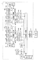
図1は、この発明の実施の形態1に従うデータ処理システムの全体の構成を概略的に示す図である。図1において、データ処理システムは、一例として、マルチメディア用システムLSI1で構成される。このシステムLSI1は、処理内容が予め割当てられるバスマスタ群2Aおよび2Bを含む。バスマスタ群2Aは、バスマスタ3a−3d、…を含み、バスマスタ群2Bは、バスマスタ3e−3h、…を含む。
[Embodiment 1]
FIG. 1 schematically shows an overall configuration of a data processing system according to the first embodiment of the present invention. In FIG. 1, the data processing system is constituted by a
バスマスタ群2Aは、一例として、画像処理を担当し、バスマスタ群2Bは、画像表示を担当する。画像処理は、入力画像の変換処理などの画像からある情報を抽出する処理を示す。画像表示は、処理画像の表示装置への表示を行い、受信画像データの表示装置への表示の処理も含む。これらのバスマスタ群2Aおよび2Bには、他の画像圧縮処理などが割当てられてもよく、マルチメディア用システムLSI1が処理するデータの種類に応じて、その処理内容が定められればよい。
As an example, the
バスマスタ3a−3hの各々は、対応のバスマスタ群2Aおよび2Bに割当てられる処理内容内の単位処理を実行する。画像処理を担当するバスマスタ群2Aにおいてバスマスタ3a−3dは、たとえば、一例として、フィルタ処理、画像の重ね合わせ、色相の変更などの処理を実行する。画像表示を担当するバスマスタ群2Bにおいては、バスマスタ3e−3hは、一例として、各々、表示画像データの倍速表示のための画像データ配列、画像データの転送周波数の変換などの処理をそれぞれ実行する。
Each of the
バスマスタ群2Aに対して、上位バスコントローラ4Aおよび上位階層バス回路6Aが設けられ、バスマスタ群2Bに対して、上位バスコントローラ4Bおよび上位階層バス回路6Bが設けられる。
An
上位バスコントローラ4Aは、バスマスタ群2Aに含まれるバスマスタ3a−3d、…とコントロールバス5Aを介して結合され、これらのバスマスタ3a−3d、…のバスアクセス要求の調停を行なう。上位階層バス回路6Aにおいては、一例として、内蔵のセレクタにより、上位バスコントローラ4Aによりアクセス要求が許可されたバスマスタを選択する。
The
上位バスコントローラ4Bも同様、コントロールバス5Bを介してバスマスタ3e−3h、…に結合され、これらのバスマスタ3e−3h、…のアクセス要求の調停を行なう。一例として、上位階層バス回路6Bにおいても、セレクタが含まれており、上位バスコントローラ4Bによりアクセス要求が許可されたバスマスタを、この内部のセレクタにより選択する。
Similarly, the
上位バスコントローラ4Aおよび4Bは、それぞれ、バスアクセス要求が許可されたバスマスタに割当てられている優先順位を示す優先順位伝達信号PRAおよびPRBを、それぞれアクセス要求が許可されたバスマスタのアクセス要求REQAおよびREQBならびにアドレス(ADD)、データ(DATA:データ書込時)およびコマンド(CTL)とともに転送する。
The
このアクセス要求が許可されたバスマスタに割当てられた優先順位を示す優先順位伝達信号PRAおよびPRBを下位階層へ伝達することにより、バスマスタ3a−3h、…においてデータ転送制限時間(優先順位)が変更される場合においても、正確なバスアクセス要求の調停を実現することができる(この動作については後に説明する)。
The data transfer time limit (priority) is changed in the
上位階層バス回路6Aおよび6Bに対し共通に、下位階層バス回路9が設けられる。下位階層バス回路9に対して下位バスコントローラ10が設けられる。上位階層バス回路6Aおよび6Bからの優先順位伝達信号PRAおよびPRBとアクセス要求REQA1およびREQBは、それぞれローカルコントロールバス7Aおよび7Bに結合されるコントロールバス8を介して下位バスコントローラ10へ与えられる。
A lower
下位バスコントローラ10は、転送された優先順位伝達信号PRAおよびPRBに従ってバスアクセス要求を調停し、一例として、下位階層バス回路9に含まれるセレクタにより、アクセス許可された上位階層バス回路6(6Aまたは6B)の出力するアドレス(ADD)、データ(DATA:データ書込時)およびコマンド(CTL)を選択する。
The lower-
下位階層バス回路9に対しては、バススレーブとして、外部メインメモリとして設けられるSDRAM(クロック同期型ダイナミック・ランダム・アクセス・メモリまたはクロック同期型半導体記憶装置)16に対するアクセスを制御するSDRAMコントローラ15が設けられる。SDRAMコントローラ15は、下位階層バス回路9から転送されたアドレス、データおよびコマンドに従って図示しないクロック信号に同期してSDRAM16へアクセスし、必要なデータの転送(書込または読出)を実行する。このSDRAMコントローラ15のアクセス制御動作は、通常のメモリコントローラのアクセス制御態様と同様である。
For the lower
下位階層バス回路9は、また、CPUバス11を介してCPU(中央演算処理装置)12に結合される。CPUバス11にはキャッシュメモリ13が設けられ、CPU12が処理を実行する際に用いられるデータおよび命令がキャッシュメモリ13にキャッシュされる。
The lower
下位階層バス回路9に対してさらに、DMAC(ダイレクト・メモリ・アクセス・コントローラ)14が設けられ、SDRAM16へのアクセスが、CPU12の制御を離れてDMAC14の制御のもとに実行される。これにより、CPU12の演算処理に並行して、SDRAM16とバスマスタとの間でデータ転送を実行する。
A DMAC (direct memory access controller) 14 is further provided for the lower
図2は、この発明の実施の形態1に従うデータ処理システムの具体的バスアクセス調停動作の一例を概略的に示す図である。図2において、一例として、バスマスタ群2Aにおいてバスマスタ3a−3dが用いられ、バスマスタ群2Bにおいては、バスマスタ3e−3hが利用される。バスマスタ群2Aのバスマスタ3a−3cに対し、データ転送制限時間として、5μs、10μs、15μsがそれぞれ割当てられる。システムの動作モードに応じて、バスマスタ3dのデータ転送制限時間が20μsから25μsに変更される。一方、バスマスタ群2Bにおいて、バスマスタ3f−3hに対して、データ転送制限時間として、30μs、35μsおよび40μsがそれぞれ割当てられる。システムの動作モードの変更に伴って、バスマスタ3eのデータ転送制限時間として25μsに代えて20μsが割当てられる。
FIG. 2 schematically shows an example of a specific bus access arbitration operation of the data processing system according to the first embodiment of the present invention. In FIG. 2, as an example,
バスマスタ3a−3hの優先順位は、バスマスタ全体においてデータ転送制限時間が短いものに高い優先順位が割当てられるように割当てられる。したがって、バスマスタ3a−3cに対して優先順位“1”、“2”、“3”が割当てられる。一方、バスマスタ3f−3hに対しては、優先順位“6”、“7”および“8”が割当てられる。一方、システムの動作モードの変更に伴い、バスマスタ3dおよび3eには、それぞれ、優先順位“5”、“4”が割当てられる。すなわち、バスマスタの優先順位は、バスマスタ群内において個々に設定されるのではなく、バスマスタ全体において、そのデータ転送制限時間に応じて割当てられる。従って、バスマスタ群2Aに含まれるバスマスタ3dの優先順位が、バスマスタ群2Bのバスマスタ3eの優先順位よりも低くなる状態が生じる。この処理モードに応じたバスマスタの優先順位の設定は、例えば、以下のようにして行なわれる。すなわち、図1に示すCPU12が、実行する処理モードに応じて各バスマスタに割り当てられるデータ転送制限時間を算出し、その算出結果に基づいて最も短いデータ転送制限時間のバスマスタから順に高い優先順位を設定する。
The priority order of the
この図2に示す状態において、今、上位階層バス回路6Aにおいては、バスマスタ3dからのバスアクセス要求が認められ、上位階層バス回路6Bにおいては、バスマスタ3eからのバスアクセス要求が認められた状態を考える。この場合、上位階層バス回路6Aは、バスマスタ3dの有する優先順位“5”を示す優先順位伝達信号PRAを下位階層バス回路9に転送する。一方、上位階層バス回路6Bは、このバスマスタ3eの有する優先順位“4”を示す優先順位伝達信号PRBを下位階層バス回路9に転送する。
In the state shown in FIG. 2, the upper
下位階層バス回路9においては、この転送された優先順位伝達信号PRAおよびPRBに基づいて、優先順位の高いバスマスタ3eのアクセス要求を選択する。したがって、上位階層バス回路6Aおよび6Bの下位階層バス回路9に対するアクセス優先順位は、固定的に上位階層バス回路6Aの方が高いように定められるのではなく、優先順位伝達信号PRAおよびPRBに従ってアクセス優先順位を判定してバスアクセス要求の調停を実行する。これにより、システムの処理動作に応じて、バスマスタのデータ転送制限時間が更新され、その優先順位が変更される場合においても、正確に、データ転送制限時間の短いバスマスタのアクセス要求を許可することができる。すなわち、固定優先方式のバスアクセス調停における、データ転送制限時間が短いバスマスタに対して高い優先順位を割当ててバスアクセス権の調停を行うという原則を、維持することができる。
The lower
下位階層バス回路9に対しては、バススレーブとしてSDRAMコントローラ14およびSDRAM16が設けられており、SDRAMコントローラ14を介してSDRAM16に対しアクセスをして、データ転送を行なう。これにより、バスマスタ3eは、設定されたデータ転送制限時間内に、必要なデータの転送を行なうことができる。
The lower
図3は、図1に示す上位バスコントローラ4A、4Bおよび上位階層バス回路6A、6Bの構成の一例を概略的に示す図である。図3において、上位バスコントローラ4Aおよび4Bが同一構成を有し、また、上位階層バス回路6Aおよび6Bも同一構成を有するため、上位バスコントローラ4により、上位バスコントローラ4Aおよび4Bを代表的に示し、上位階層バス回路6により、上位階層バス回路6Aおよび6Bを代表的に示す。
FIG. 3 schematically shows an example of the configuration of
図3において、上位バスコントローラ4(4A,4B)は、各バスマスタの優先順位を示す情報を格納するレジスタファイル20と、バスマスタからのバスアクセス要求REQ1−REQnに従ってレジスタファイル20を参照してバスアクセス要求の調停を行なうバスアクセス調停部22と、レジスタファイル20の各バスマスタの優先順位をCPU12からの指令に従って変更する書換制御回路24とを含む。
In FIG. 3, the upper bus controller 4 (4A, 4B) accesses the bus by referring to the
レジスタファイル20は、各バスマスタに対応して配置されるエントリERYを含む。これのエントリERYは、それぞれ、バスマスタを特定するバスマスタIDを格納する識別フィールドFD1と、各バスマスタに割当てられた優先順位を示す情報を格納する優先順位フィールドFD2を含む。
The
但し、このレジスタファイル20の構成としては、夫々のエントリERYを対応するバスマスタに括り付けて(エントリERYの一番目をバスマスタ3a、二番目のエントリをバスマスタ3B、…等)優先順位を示す情報を格納するものであってもよく、逆に、夫々のエントリERYを対応する優先順位に括り付けてバスマスタを特定するバスマスタ識別子IDを格納するものであってもよく、構成上の都合に応じて決定されればい。
However, the configuration of the
図3においては、一例として、レジスタファイル20内において、n個のバスマスタに対して割当てられるバスマスタ識別子ID1−IDnと、バスマスタそれぞれに対して割当てられる優先順位を示す情報PR1−PRnが格納される。
In FIG. 3, as an example, in the
バスアクセス調停部22は、コントロールバス5(5A,5B)を介して与えられるバスマスタからのバスアクセス要求REQ1−REQnを受けると、バスアクセス要求が競合するとき、レジスタファイル20を参照し、最も優先順位の高いバスマスタのバスアクセス要求を識別し、この最も優先順位の高いバスマスタに対しバスアクセス要求を許可するバスアクセス許可ACKをアサートする。
When the bus
バスアクセス調停部22からのバスアクセス許可ACK1−ACKnのうちの1つがアサートされ、コントロールバス5を介してそれぞれ対応のバスマスタに転送される。バスマスタは、対応のバスアクセス許可ACKi(i=1−nのいずれか)がアサートされると、対応の上位階層バス回路に対してSDRAMへのデータ転送要求(データの書込または読出要求)を発行する。他のバスマスタは、自身に割当てられたバスアクセス許可ACKiがアサートされるまで、バスアクセスは待ち合わせられる。
One of the bus access grants
書換制御回路24は、CPU12から書換指示が与えられると、レジスタファイル20内の対応のバスマスタの優先順位を書換える。CPU12は、バスコントローラ4とCPUバス11を介して結合され、システムの動作モードが変更され、各バスマスタに割当てられるデータ転送制限時間が変更されると、その変更に応じて、各バスマスタに対する優先順位を再編成する。この優先順位の再編成は、一例として、以下のようにして行なわれる。すなわち、テーブルメモリ内に、システムの処理モードに応じて各バスマスタに割当てられるデータ転送制御時間を各バスマスタに対応して格納する。CPU12は、処理モード変更が指示されると、その変更後の処理モードに基いてテーブルメモリを参照して、各バスマスタのデータ転送制御時間情報を読出し、全バスマスタに対して、この読出したデータ転送制限時間の昇順に従って、優先順位を降順に割当てる(短いデータ転送制御時間に対してより高い優先順位を割当てる)。
The
CPU12は、実行する処理モードに応じて再編成された各バスマスタの優先順位情報を生成すると、一旦、レジスタファイルに生成したバスマスタの優先順位情報を格納する。この後、CPU12は、CPUバス11を介して書換制御回路24に対し優先順位書換指示を与え先順位変更対象のバスマスタを特定するアドレス(バスマスタ識別情報ID)および対応の優先順位情報を転送する。これにより、各システム動作モードに応じてバスマスタの優先順位が変更される場合においても、各バスマスタに対して、最もデータ転送制限時間が短いバスマスタを優先的にアクセス許可するという固定優先方式のバスアクセス権調停の原則を維持することができる。
When the
上位階層バス回路6(6A,6B)は、バスアクセス調停部22からのバスアクセス許可ACK1−ACKnに従ってバスマスタ群2(2A,2B)の出力情報を選択するセレクタ26と、下位階層に対するバスアクセス要求IDQAおよびアクセス許可されたバスマスタの優先順位を示す信号PRAを伝達するバッファ28を含む。
The upper hierarchy bus circuit 6 (6A, 6B) includes a
セレクタ26は、バスアクセス調停部22からのバスアクセス許可ACK1−ACKnに従って、アサートされたバスアクセス許可に対応するバスマスタの出力を対応のバスマスタ群2から選択し、アクセス許可されたバスマスタから転送されたアドレスADD、データDATAおよびコマンドCTLを下位階層バス回路に転送する。
The
バスマスタ群2は、データ読出を要求し、SDRAM(16)からデータの転送を要求する場合には、対応のバスマスタは、アドレスおよび読出モード指示を出力し、セレクタ26からは、これらのアドレスADDおよび読出モードを指定するコマンドCTLが出力される。所定期間経過後、セレクタ26を介してバスマスタ群2のアクセスが許可されたバスマスタに対し、SDRAMからの読出データDATAが転送される。
When
バッファ28は、バスアクセス調停部22からのバスアクセス要求およびアクセス許可されたバスマスタの優先順位情報を受け、バッファ処理して下位階層に対するバスアクセス要求REQ(REQA、REQB)および優先順位伝達信号PR(PRA、PRB)を生成する。
The
なお、この図3に示す構成において、上位階層バス回路6においては、セレクタ26によりバスマスタ群2に含まれるバスマスタの出力を選択している。しかしながら、以下の構成の場合には、このセレクタ26は、設ける必要はない。すなわち、バスマスタ群2に含まれるバスマスタの出力部(インターフェース部)が、上位階層バスに並列に結合され、バスマスタは、それぞれ、対応のバスアクセス許可ACK1−ACKnがアサートされるときに出力がイネーブルされ、対応のバスアクセス許可ACKiがネゲート状態の場合には、バスマスタが出力ハイインピーダンス状態に維持される。この構成の場合には、セレクタ26は、機能的には、バス回路6に含まれる上位階層バスと、各バスマスタの出力部に設けられるバスインターフェイスとの組合せに対応することになる。
In the configuration shown in FIG. 3, in the upper
図3に示す構成を利用することにより、システム動作モードに応じてバスマスタの優先順位が変更される場合においても、上位階層バス回路6におけるバッファ28により、下位階層バス回路またはバススレーブへ更新後の優先順位情報を伝達することができる。
By using the configuration shown in FIG. 3, even when the priority order of the bus master is changed according to the system operation mode, the
[バスコントローラの構成]
図4は、図1に示す下位階層バス回路9および下位バスコントローラ10の構成を概略的に示す図である。図4において、下位バスコントローラ10は、上位階層バス回路2Aおよび2Bから転送される優先順位伝達信号PRAおよびPRBのうち最も高い優先順位を選択する最高優先順位選択部50と、これらの上位階層バス回路2Aおよび2Bからの転送要求REQAおよびREQBと優先順位伝達信号PRAおよびPRBに従って競合アクセスを調停する転送要求調停部50を含む。
[Bus controller configuration]
FIG. 4 schematically shows configurations of lower
最高優先順位選択部50は、上位階層バス回路2Aおよび2Bからのアクセス要求(転送要求)REQAおよびREQBがともにアサートされているとき、並行して伝達される優先順位伝達信号PRAおよびPRBのうち高いほうの優先順位を示す優先順位値を選択してバススレーブまたは下位階層バス回路に対し優先順位伝達信号PR(L)を生成して伝達する。この最高優先順位選択部50は、アクセス要求REQAおよびREQBの一方のみがアサートされている場合には、対応の優先順位伝達信号を選択して下位階層バス回路またはバススレーブに伝達する。
Highest
この最高優先順位選択部50は、また、転送要求調停部52が生成したアクセスが許可されたバスを示す最終バスアクセス許可FBACKAおよびFBCKABを、上位バスコントローラ4Aおよび4Bへそれぞれ転送する。下位階層バス回路においてアクセスが許可されたバスマスタに対して、最終のバスアクセス許可ACKを生成して、バスマスタの転送動作を許可する。下位階層バス回路によりアクセスが待ち合わせられるバスマスタは、データ転送を以後に許可されるまで待合せる。この最終バスアクセス許可FBACKAおよびFBACKBを用いた転送処理については、後に詳細に説明する。
The highest
転送要求調停部52は、これらの転送要求REQAおよびREQBと優先順位伝達信号PRAおよびPRBとに従って、最も優先順位の高い上位階層バス回路またはバスマスタを指定する選択信号SELを生成するとともに、下位階層バス回路またはバススレーブに対しアクセス要求REQ(L)および対応の優先順位伝達信号に従って下位への優先順位伝達信号PR(L)を生成して転送する。
The transfer
下位階層バス回路9は、セレクタ部54を含む。セレクタ部54は、上位階層バス回路2Aおよび2Bからのアドレス信号、データおよびコマンドADD/DATA/CTL♯AおよびADD/DATA/CTL♯Bの一方を、転送要求調停部52からの選択信号SELに従って選択し、下位階層バス回路またはバススレーブに対するアドレス、データおよびコマンド(ADD/DATA/CTL)を転送する。
The lower
この下位バスコントローラ10において、アクセス要求(転送要求)REQAおよびREQBがともにアサートされているとき、伝達された優先順位伝達信号PRAおよびPRBのうち高いほうの優先順位を示す上位階層バス回路またはバスマスタを選択する。これにより、下位階層バス回路9において、バスマスタの優先順位が変更されていても、伝達された優先順位伝達信号PRAおよびPRBにより高いほうの優先順位を有する上位階層バス回路(またはバスマスタ)を選択して下位階層バス回路またはバススレーブへ上位からの転送情報(アドレス、データおよびコマンド)を転送することができる。
In this
図5は、この発明の実施の形態1に従うデータ処理システムのデータ転送制御の構成を概略的に示す図である。図5において、下位バスコントローラ10は、その内部に含まれる最高優先順位選択部50においてアクセス許可されたバスマスタを示す最終バスアクセス許可FBACKAおよびFBACKBを生成し、それぞれ、上位バスコントローラ4Aおよび4Bへ与える。
FIG. 5 schematically shows a data transfer control configuration of the data processing system according to the first embodiment of the present invention. In FIG. 5, the lower-
上位バスコントローラ4Aおよび4Bは、最終バスアクセス許可FBACKAおよびFBACKBのアサート時、対応の上位階層バス回路6Aおよび6Bにおいてアクセス許可されたバスマスタ3Aおよび3Bに対して、データ転送許可DTXENAおよびDTXENBをアサートする。バスマスタ3Aおよび3Bは、それぞれ、データ転送許可DTXENAおよびDTXENBのアサート時、データ転送を実行する。このときには、すでに、上位バスコントローラ4によりアクセスが許可されたバスマスタは、対応のバスアクセス許可ACKiに従って転送がイネーブル状態に設定されている。書込データの転送を行なうライトデータ転送時においては、残りの書込データの転送を行なう。一方、読出データ転送時においては、SDRAM(16)から転送されたデータが、対応の最終にバスアクセスが許可されたバスマスタに転送される。
すなわち、上位バスコントローラ4Aおよび4Bは、バスアクセスが許可されたバスマスタをバスアクセス許可ACKiにより識別し、最終バスアクセス許可FBACKAおよびFBACKBのアサート時、アサート状態のバスアクセス許可ACKiに対応するバスマスタに対して、データ転送許可DTXENAおよびDTXENBをアサートする。各バスマスタにおいて、バスアクセス許可ACKiと最終バスアクセス許可FBACK(FBACKAまたはFBACKB)との論理積演算を行なうことにより、両者がアサートされたバスマスタに対するデータ転送を許可することができる。
That is, the higher-
なお、上述の構成において、階層バス構造は、上位階層バス回路および下位階層バス回路の2段階のバス構成とされる。しかしながら、さらに複数のバス階層が設けられていてもよい。また、上位階層バス回路が、下位階層バス回路に対し2つ設けられているだけである。しかしながら、1つの下位階層バス回路に対し2よりも大きい複数の上位階層バス回路が配置され、バスマスタが3以上のバスグループに分割されてもよい。 In the configuration described above, the hierarchical bus structure is a two-stage bus configuration of an upper hierarchical bus circuit and a lower hierarchical bus circuit. However, a plurality of bus hierarchies may be provided. Further, only two upper layer bus circuits are provided for the lower layer bus circuit. However, a plurality of upper layer bus circuits larger than 2 may be arranged for one lower layer bus circuit, and the bus master may be divided into three or more bus groups.
個々に上位階層バス回路により優先順位の判定を行ない、また、下位階層バス回路においては、伝達された優先順位情報に従って最も高い優先順位のバスマスタを選択する。 The priority order is individually determined by the upper hierarchy bus circuit. In the lower hierarchy bus circuit, the bus master having the highest priority is selected according to the transmitted priority information.
以上のように、この発明の実施の形態1に従えば、上位から下位に向かって、選択されたバスマスタの優先順位を示す優先順位情報を伝達している。これにより、データ転送制限時間の値がある範囲のバスマスタをまとめてグループ化し、各グループをそれぞれ1つの上位階層バス回路に接続することが特に要求されない。これにより、バス構成の自由度を改善することができる。また、システムの動作モードが変更され、バスマスタのデータ転送制限時間が変更された場合でも、優先順位を変更することにより、データ転送制限時間が短いバスマスタに対してより高い優先順位を与えるという原則を維持することができる。 As described above, according to the first embodiment of the present invention, the priority order information indicating the priority order of the selected bus master is transmitted from the higher order to the lower order. Thus, it is not particularly required to group bus masters within a certain range of data transfer time limit values and connect each group to one upper hierarchy bus circuit. Thereby, the freedom degree of a bus structure can be improved. Also, even when the system operation mode is changed and the data transfer time limit of the bus master is changed, the principle of giving higher priority to the bus master with a short data transfer time limit by changing the priority order. Can be maintained.
この図1に示す構成において上位階層バス回路と下位階層バス回路の間に、バスブリッジが設けられてもよい。データバス幅の変更およびデータ転送タイミングの調整をこのバスブリッジを用いて行なう。 In the configuration shown in FIG. 1, a bus bridge may be provided between the upper hierarchy bus circuit and the lower hierarchy bus circuit. The bus bridge is used to change the data bus width and adjust the data transfer timing.
また、バスマスタがリードデータ転送を要求する場合、下位階層バス回路でアクセスが待ち合わせられた場合、アクセスが待合せ状態のバスマスタに対するデータ転送を待ち合わせる必要がある。この場合、下位バスコントローラ10からのバスアクセス許可FBACKに従って、上位バスコントローラ4が、アクセス許可されたバスマスタに対し、要求したデータが、SDRAMから転送されたことを報知する構成が用いられてもよい。
When the bus master requests read data transfer, when access is queued in the lower hierarchy bus circuit, it is necessary to wait for data transfer to the bus master whose access is queued. In this case, according to the bus access permission FBACK from the
[実施の形態2]
図6は、この発明の実施の形態2に従うデータ処理システムの構成を概略的に示す図である。この図6に示すデータ処理システム1においては、上位階層バス回路6Aおよび上位階層バス回路6Bそれぞれと下位階層バス回路9の間にバスブリッジ60Aおよび60Bが設けられる。これらのバスブリッジ60Aおよび60Bは、それぞれキューバッファ62Aおよび62Bを含む。
[Embodiment 2]
FIG. 6 schematically shows a configuration of a data processing system according to the second embodiment of the present invention. In the
これらのキューバッファ62Aおよび62Bは、対応の上位階層バス回路6Aおよび6Bからそれぞれ転送されるアドレス、データおよびコマンド(ADD/DATA/CTL)に加えて、バスアクセス要求REQ(REQA,REQB)および優先順位伝達信号PRAをそれぞれFIFO(ファーストイン・ファーストアウト)態様で格納する。キューバッファ62Aおよび62Bは、たとえば複数段のフリップフロップ(FF)で構成され、複数のバスマスタからのバスアクセス要求を待ち行列化することができる。図6に示すデータ処理システム1の他の構成は、図1に示すデータ処理システムの構成と同じであり、対応する部分には同一参照番号を付し、その詳細説明は省略する。
These queue buffers 62A and 62B include bus access requests REQ (REQA, REQB) and priority in addition to addresses, data and commands (ADD / DATA / CTL) transferred from the corresponding upper
図7は、図6に示すデータ処理システムのアクセス要求選択態様を、バスブリッジの構成の一例とともに示す図である。図7において、バスブリッジ60Aおよび60Bにおいて、キューバッファ62Aおよび62Bは、それぞれ、2段のバッファレジスタ64を含む。キューバッファ62Aおよび62Bのバッファレジスタの段数は、システムの要求に応じて決定される。
FIG. 7 is a diagram showing an access request selection mode of the data processing system shown in FIG. 6 together with an example of the configuration of the bus bridge. In FIG. 7, in the
また、バスマスタ群2Aにおいては、バスマスタ3a−3dが設けられ、バスマスタ群2Bにおいては、バスマスタ3e−3hが設けられる。
In the
バッファレジスタ64は、バスアクセス要求REQ(REQA,REQB)を格納するバスアクセス要求フィールド65aと、転送アドレスを格納するアドレスフィールド65bと、優先順位伝達信号を格納する優先順位フィールド65cと、転送データを格納するデータフィールド65dとを含む。転送アドレスは、SDRAM16のメモリアクセス位置を示すアドレスである。転送データは、書込アクセス時にSDRAM16に転送されるデータである。
The
図7において、いま、キューバッファ62Aにおいては、バスマスタ3cの転送するアドレスAD(c)がその対応の優先順位“3”を示す情報および転送データDATA(c)とともにフィールド65b、65cおよび65dにそれぞれ格納され、また、バスマタ3dが転送するアドレスAD(d)とリンクして、バスマスタ3dの優先順位“5”を示す情報が転送データDATA(d)とともに、それぞれ、フィールド65b、65cおよび65dに格納され、この場合、アクセス要求を行なっているため、バスアクセス要求REQAがアサートされて対応のバスアクセス要求フィールド65aに格納される。
In FIG. 7, in the
キューバッファ62Bにおいては、バスマスタ3eが転送するアドレスAD(e)とリンクしてこのバスマスタ3eの優先順位“4”を示すデータおよび転送データDATA(e)、それぞれ、フィールド65b、65cおよび65dに格納される。また、バスマスタ3fの転送アドレスAD(f)が、その優先順位“6”とともにリンクしてフィールド65bおよび65cに格納される。また、上位階層バス回路6Bからアクセス要求が行なわれており、バスアクセス要求REQBがアサートされて各対応のバスアクセス要求フィールド65aに格納される。
In the
上述のように、バッファレジスタ64は、一例として、フリップフロップ(FF)で構成される。上位階層バス回路6Aおよび6Bからバスアクセス要求が優先順位伝達信号とともに転送されるごとに、キューバッファ62Aおよび62Bに順次FIFO(ファーストイン・ファーストアウト)態様で対応の上位バス回路6Aおよび6Bからの転送情報がそれぞれ格納される。各クロック信号に同期して、キューバッファ62Aおよび62Bそれぞれから、最初に格納されたバッファレジスタ64の内容が、下位バスコントローラ10に転送され、さらに、バスアクセス要求の調停が行なわれる。
As described above, the
図7に示す配置においては、下位階層バス回路9において、バスマスタ3cおよび3eからのアクセス要求の調停が行なわれる。バスマスタ3cの優先順位が“3”であり、バスマスタ3eの優先順位が“4”である。従って、キューバッファ62Aからの転送アドレスAD(c)および転送データDATA(c)が選択され、対応の優先順位伝達信号とともに下位階層バス回路9を介してSDRAMコントローラ15に転送される。転送データDATAは、SDRAMに対する書込データである。
In the arrangement shown in FIG. 7, the access request from the
なお、データ転送についても、キューバッファ62Aおよび62B内にバッファレジスタがそれぞれ書込データ転送経路および読出データ転送経路に設けられる。上述の転送データDATAを格納するバッファレスタ65dは、書込データ転送部において設けられ、アドレスと同様にバッファレジスタ65dに転送データが、FIFO態様で格納される。一方、読出データ転送経路においては、SDRAMコントローラ15を介して転送されるデータをFIFO態様で格納して上位階層バス回路6Aおよび6Bに転送するFIFOバッファレジスタが設けられる。この場合、下位バスコントローラ10においては、先の実施の形態1において図4および7を参照して説明したように、読出データ転送時、最終バスアクセス許可FBACKAおよびFBACKBに従って読出データ転送を要求したバスマスタが特定されてイネーブルされるため、読出データがアクセス要求したバスマスタに対して正確にFIFO態様で転送される。
For data transfer, buffer registers are provided in the write data transfer path and the read data transfer path in
したがって、上位階層バス回路6Aおよび6Bの内部構成およびこの上位バスコントローラ、および下位階層バス回路9および下位バスコントローラ10の構成としては、先の実施の形態1において説明した構成を利用することができる。
Therefore, the configuration described in the first embodiment can be used as the internal configuration of upper
なお、この図7に示す構成においてキューバッファ62Aおよび62Bにおいてバスアクセス要求REQAおよびREQBが格納されている。この構成の場合、キューバッファ62Aおよび62Bに、さらに、各バスアクセスを要求するバスマスタを識別するバスマスタ識別子IDを格納し、下位バスコントローラ10においては、最終的にバスアクセスが許可されたバスマスタを、転送されたバスマスタ識別子に基づいて判別して、最終バスアクセス許可を、バスマスタ識別子とともに上位バスコントローラに転送する構成が用いられてもよい。上位バスコントローラが、最終バスアクセス許可FBACKおよびバスマスタ識別子IDとに基いて、アクセス許可されたバスマスタを識別して、転送データ取り込みイネーブル状態に設定してもよい。
In the configuration shown in FIG. 7, bus access requests REQA and REQB are stored in
以上のように、この発明の実施の形態2に従えば、バスブリッジ内において、バスブリッジ内に、優先順位を示す優先順位を格納するバッファを配置しており、この格納した優先順位情報を下位階層バス回路に伝達することができる。したがって階層バス構造において、この上位階層バスと下位階層バスの間にバスブリッジが配置される場合においても、正確に上位階層バスから下位階層バスに優先順位を示す情報を伝達することができ、実施の形態1において示す構成と同様の効果を得ることができる。また、上位および下位階層バス回路において、パイプライン的にバスアクセス調停を行うことができ、上位階層バス回路においても、下位階層バス回路での調停結果により、調停を待合せる必要がなく、高速処理が実現される。
As described above, according to the second embodiment of the present invention, in the bus bridge, the buffer for storing the priority order indicating the priority order is arranged in the bus bridge, and the stored priority order information is subordinate to the lower order. It can be transmitted to the hierarchical bus circuit. Therefore, in the hierarchical bus structure, even when a bus bridge is arranged between the upper hierarchy bus and the lower hierarchy bus, information indicating the priority can be accurately transmitted from the upper hierarchy bus to the lower hierarchy bus. The effect similar to the structure shown in the
[実施の形態3]
図8は、この発明の実施の形態3に従うデータ処理システムの構成を概略的に示す図である。図8に示すデータ処理システムにおいては、バスブリッジ60Aおよび60Bにおいて、さらに、セレクタ70Aおよび70Bが設けられる。セレクタ70Aは、キューバッファ62Aに格納される優先順位情報すべてと上位階層バス回路6Aから転送される優先順位伝達信号PRAとを受け、これらの優先順位を判定し、最も優先順位の高い優先順位伝達信号を選択する。セレクタ70Bも、同様、キューバッファ62Bに格納される全ての優先順位情報と、上位階層バス回路6Bから与えられる優先順位伝達信号PRBとを受け、これらの与えられた優先順位情報のうち最も優先順位の高い優先順位情報を選択して出力する。
[Embodiment 3]
FIG. 8 schematically shows a structure of a data processing system according to the third embodiment of the present invention. In the data processing system shown in FIG. 8,
キューバッファ62Aおよび62Bには、複数のバスマスタからのバスアクセス要求REQが、優先順位情報PRiとともにリンクして格納される。セレクタ70Aおよび70B各々は、対応のバスアクセス要求REQがアサートされているとき、対応の優先順位情報をすべて比較する。
In the queue buffers 62A and 62B, bus access requests REQ from a plurality of bus masters are stored linked with priority information PRi. Each of the
図8に示すデータ処理システムの他の構成は、図6に示すデータ処理システムの構成と同じであり、対応する部分には同一参照番号を付し、その詳細説明は省略する。 The other configuration of the data processing system shown in FIG. 8 is the same as the configuration of the data processing system shown in FIG. 6, and corresponding portions are denoted by the same reference numerals, and detailed description thereof is omitted.
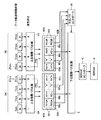
図9は、図8に示すデータ処理システムの転送処理動作の一例を概略的に示す図である。図9において、バスマスタ群2Aにおいて、バスマスタ3a−3dが用いられ、バスマスタ群2Bにおいてバスマスタ3e−3hが用いられる。
FIG. 9 is a diagram schematically showing an example of the transfer processing operation of the data processing system shown in FIG. In FIG. 9,
バスマスタ群2Aにおいて、バスマスタ3a、3b、3cおよび3dに対し優先順位“1”、“2”、“5”、および“6”が割当てられる。一方、バスマスタ群2Bにおいて、バスマスタ3e、3f、3gおよび3hに対しそれぞれ、優先順位“3”、“4”、“7”および“8”が割当てられる。すなわち、上位階層バス回路6Aにおいて、バスマスタ3c、3dおよび3eが順次アクセス要求が許可され、また、上位階層バス回路6Bにおいて、バスマスタ3g、3hおよび3iが順次バスアクセスが許可された状態を考える。
In the
この場合、バスブリッジ62Aにおいて、バスマスタ3cに対して、キューバッファ62Aのバッファレジスタに、バスアクセス要求REQA、アドレスA0(c)および優先順位情報“5”が格納される。次のバッファレジスタ64において、バスマスタ3dに対するバスアクセス要求REQA、アドレスA(d)および優先順位情報“6”が格納される。また、この状態において、上位階層バス回路6Aから、次のバスマスタ3cからのアクセス要求に従って転送先アドレスA1(c)が優先順位情報“5”とともに転送される。この場合、キューバッファ62Aにおいては、バッファレジスタ64すべてに有効情報が格納されており、上位階層バス回路6Aから転送されるアドレスA1(c)および優先順位情報“5”は待ち合わせられる。
In this case, in the
一方、バスブリッジ60Bにおいて、キューバッファ62Bにおいて、バスマスタ3gからのバスアクセス要求REQBが転送要求アドレスA(g)と優先順位情報“7”が格納される。またバスマスタ3hからの要求に従ってバスアクセス要求REQB、転送先アドレスA(h)および優先順位情報“8”が格納される。次のサイクルにおいて、バスマスタ3eからの転送要求アドレスA(e)が優先順位情報“3”とともにキューバッファ62Bに与えられてその格納が待ち合わせられる。
On the other hand, in the
なお、キューバッファ62Aおよび62Bにおいて、先の実施の形態2と同様、転送データを格納するデータフィールドが設けられるが、図9においては、図面の煩雑化を避けるために示していない。アドレス信号の転送経路に関連する部分のみを示す。
In
この状態において、セレクタ70Aは、対応のキューバッファ62Aに格納される有効優先順位情報および上位バス回路からの優先順位伝達信号のすべてを受け、最も優先順位の高い優先順位情報を選択して優先順位伝達信号PRAを生成する。セレクタ70Bも、キューバッファ62Bに格納されるフィールド65cに格納される優先順位情報および上位バス回路6Bからの待合せ状態の優先順位伝達信号を並列に受け、最も優先順位の高い優先順位を選択して優先順位伝達信号PRBを生成する。このセレクタ70Aおよび70Bからの優先順位伝達信号PRAおよびPRBが、下位バスコントローラ10へ与えられる。このとき下位階層バス回路9において、バスブリッジ60Aおよび60Bから転送されたアドレス(およびデータ)の転送制御を行なう。
In this state, the
図10は、図9に示すデータ処理システムの動作を示すタイミング図である。以下、図10を参照して、図9に示すアクセス要求調停動作について説明する。 FIG. 10 is a timing chart showing the operation of the data processing system shown in FIG. The access request arbitration operation shown in FIG. 9 will be described below with reference to FIG.
バスブリッジ60Aおよび60Bにおけるキューバッファ62Aおよび62Bは、クロック信号CLKに同期して動作する。
The queue buffers 62A and 62B in the
サイクル♯1において、セレクタ70Aは、優先順位として“5”、“6”および“5”が与えられており、優先順位伝達信号PRAとして、最も優先順位の高い優先順位“5”を選択して下位バスコントローラ10へ対応のアドレスおよびデータとともに与える。一方、セレクタ70Bは、優先順位として“7”、“8”および“3”を受け、最も高い優先順位“3”を選択して優先順位伝達信号PRBを生成して下位バスコントローラ10へ与える。
In the
したがって、この場合、上位階層バス回路6Aおよび6Bに対してはそれぞれ、優先順位“5”および“3”が割当てられる。このとき、下位階層バス回路9に対しては、キューバッファ62Aおよび62Bのアドレスフィールド65bに格納されるアドレス(および転送データ)が並行して与えられる。下位階層バス回路9においては、下位バスコントローラ10の制御のもとに、優先順位“3”が割当てられたキューバッファ62BからのアドレスA(e)が選択されてSDRAMコントローラ15へ与えられる。
Therefore, in this case, priority levels “5” and “3” are assigned to the upper
次のサイクル♯2において、キューバッファ62Aの内容の発行は行なわれていないため、セレクタ70Aは、サイクル♯1と同様に、優先順位伝達信号PRAとして、優先順位“5”を選択して下位バスコントローラ10へ与える。セレクタ70Bは、このとき、優先順位“3”を選択して優先順位伝達信号PRBを生成して下位バスコントローラ10へ与える。ここで、クロック信号CLKに同期してキューバッファ62Bにおいては、バスマスタ3gからの転送アドレスおよび転送データが下位階層バス回路9へ発行されており、バスマスタ3eからの優先順位伝達信号PR2(=“3”)および対応ORドレス信号A(e)がキューバッファ62Bのバッファレジスタ64に格納される。
Since the contents of the
このときには、下位階層バス回路9においては、バスブリッジ62Aおよび62Bからの優先順位情報“5”および“3”に従って、キューバッファ62Bのアドレスフィールド65bの次のアドレスA(h)に優先順位“3”が割当てられており、このアドレスA(h)が対応の転送データおよび優先順位伝達信号PR(=”3”)とともに下位階層バス回路9を介してSDRAMコントローラ15へ転送される。
At this time, in the lower
次のサイクル♯3においても、バスブリッジ60Aのキューバッファ62Aおよび上位階層バス回路6Aの出力優先情報は変化しないため、セレクタ70Aは、これまでのサイクルと同様、優先順位“5”を示す情報を選択して出力する。
In the
バスブリッジ60Bにおいては、セレクタ72Bが、優先順位“3”を選択して、優先順位伝達信号PRBを生成して下位バスコントローラ10へ与える。下位階層バス回路9は、バスブリッジ60Bからの優先順位伝達信号PRBが、優先順位“3”を示しており、下位バスコントローラ10の制御の下に、バスブリッジ60Bからのアドレス信号A(e)を選択して対応の転送データとともに下位階層バス回路9へ転送する。
In the bus bridge 60 </ b> B, the selector 72 </ b> B selects the priority “3”, generates the priority transmission signal PRB, and supplies it to the
サイクル♯3において、バスブリッジ60B内のキューバッファ62Bに格納されたアドレスすべての転送が完了すると、上位階層バス回路6Bからの優先順位情報はすべて転送されており、以後のサイクルにおいては無視される(以後のサイクルにおいてバスマスタ群2Bからのアクセス要求は発行されないとする。
When transfer of all addresses stored in the
サイクル♯4においては、キューバッファ62Aから、優先順位“5”がセレクタ70Aにより選択されて出力される。従って、キューバッファ62Aのアドレスフィールド65aに格納されるアドレスA0(c)、A(d)およびA1(c)が対応の転送データとともに、クロックサイクル♯4、♯5および♯6において、それぞれ、選択されて下位バスコントローラ10へ与えられる。
In
この図9に示すように、優先順位が高いバスマスタ3eがアクセス要求を発行した場合、バスマスタ3eの待ち合わせは、先に格納された優先順位の低いアドレス情報の転送の後、続いて実行することができ、この優先順位の高いバスマスタ3eの待ち合わせ時間を短縮することができる。
As shown in FIG. 9, when the
これにより、以下のような状況を回避することができる。すなわち、キューバッファ62Aにバスマスタ3cおよび3dからの転送情報が格納され、また、キューバッファ62Bにバスマスタ3gおよび3hからの転送情報が格納された後、バスマスタ3cおよびバスマスタ3eが、上位バス回路6Aおよび6Bにより選択された状態を考える。この場合、セレクタ70Aおよび70Bが設けられていない場合、以下のようにアクセス調停が行われる。バスブリッジ60Aに格納される優先順位“5”および“6”および次の優先順位“5”のバスマスタ3c、3dおよび3cからのアクセス要求の発行が完了した後に、バスブリッジ60Bの優先順位“7”および“8”を有するバスマスタ3gおよび3hのアドレスおよびデータの転送が行われる。この後に、優先順位“3”を有するバスマスタ3eが、アクセスが許可されアドレスおよびデータの転送が実行される。この場合、優先順位の高いバスマスタ3eの待合せ時間が長くなり、効率的なデータ転送を実現することができなくなり、また、バスマスタ3eのデータ転送制限時間内に必要データを転送することができなくなり、データ処理を正確に行なうことができなくなる。
Thereby, the following situations can be avoided. That is, transfer information from the
従って、図8および図9に示すように、バスブリッジ60Aおよび60B内にセレクタを設けて、各バスブリッジに対する優先順位の最も高い優先順位を選択して下位階層バス回路に転送することにより、優先順位の高いバスマスタのアクセス要求の待合せ時間を短縮することができる。
Accordingly, as shown in FIGS. 8 and 9, a selector is provided in the
また、単に優先順位を選択しているだけであり、データ転送要求の発行順序は変更されていない。従って、システム内において必要とされるデータの転送順序を維持することができ、データ処理順序が維持され、処理データのインテグリティ(integrity)を確保することができ、正確なデータ処理を保障することができる。 Also, the priority order is simply selected, and the data transfer request issuance order is not changed. Therefore, the data transfer order required in the system can be maintained, the data processing order can be maintained, the integrity of the processing data can be ensured, and accurate data processing can be ensured. it can.
以上のように、この発明の実施の形態3に従えば、各上位バス回路において、複数の優先順位情報のうち最も優先順位の高いバスマスタの優先順位を選択している。したがって、優先順位の高いバスマスタのアクセス要求が、優先順位の低いバスマスタのアクセス要求により待ち合わせられる時間を、短くすることができ、処理効率を改善することができる。 As described above, according to the third embodiment of the present invention, the priority order of the bus master having the highest priority order among the plurality of priority order information is selected in each higher-order bus circuit. Accordingly, it is possible to shorten the time that an access request of a bus master having a high priority is waited for by an access request of a bus master having a low priority, and the processing efficiency can be improved.
なお、上述の構成においては、各バスマスタに対して優先順位が各処理モードにおいて固定的に割当てられている。しかしながら、各バスマスタに対して割当てられる優先順位情報として、たとえば、バスマスタのアクセス待ち合わせ時間、またはトランザクション回数に基づいて待ち合わせ時間の最も長いものを優先順位が最も高い情報として転送する、または、トランザクション回数が最も少ない回数を、最も優先順位の高い優先順位情報として生成し、これらの優先順位情報を、各バスマスタの優先順位情報をとして用いて、これまでの実施の形態1から3の方式に従ってバスアクセスの調停を処理する構成が利用されてもよい。 In the above configuration, the priority order is fixedly assigned to each bus master in each processing mode. However, as priority information assigned to each bus master, for example, the bus master access waiting time or the longest waiting time based on the number of transactions is transferred as the highest priority information, or the number of transactions is The smallest number of times is generated as the priority information with the highest priority, and these priority information is used as the priority information of each bus master in accordance with the methods of the first to third embodiments so far. A configuration for processing arbitration may be used.
従って、上位バス回路において与えられる優先順位情報が各処理モード毎に固定的に設定される調停方式に加えて、バスマスタの優先順位が、バスアクセス要求の発効状況に応じて変更されるバスアクセス調停方式に対しても、本発明は適用することができる。 Therefore, in addition to the arbitration method in which priority order information given in the upper bus circuit is fixedly set for each processing mode, the bus master priority is changed according to the status of the bus access request. The present invention can also be applied to the system.
この発明は、複数のバスマスタを含み、優先順位に従ってバススレーブに対するアクセス要求が調整される階層バス構造のデータ処理システムに適用することにより、階層バス構造において正確に、優先順位に従ってバスアクセスを調停することができる。特に、固定優先調停方式を用いる階層バス構造のデータ処理システムに適用することにより、システムの動作モードに応じて優先順位が更新される場合においても、正確に、短いデータ転送制限時間に高い優先順位を割当てるという優先順位設定原則を維持して、バスアクセスの調停を行なうことができる。 The present invention includes a plurality of bus masters, and is applied to a data processing system having a hierarchical bus structure in which access requests to bus slaves are adjusted according to priority, thereby arbitrating bus access accurately according to priority in the hierarchical bus structure. be able to. Especially when applied to a hierarchical bus structure data processing system using a fixed priority arbitration method, even when the priority is updated according to the operation mode of the system, the priority is accurately set to a short data transfer time limit. It is possible to arbitrate bus access while maintaining the priority setting principle of allocating.
1 マルチメディアシステムLSI、2,2A,2B バスマスタ群、3a−3h バスマスタ、6,6A,6B 上位階層バス回路、9 下位階層バス回路、4,4A,4B 上位バスコントローラ、10 下位バスコントローラ、20 レジスタファイル(テーブルメモリ)、22 バスアクセス調停部、26 セレクタ、28 バッファ、44 優先順位生成部、45 CPUインターフェイスI/F、46 優先順位レジスタ、47 選択レジスタ、48 セレクタ、12 CPU、50 最高優先順位選択部、52 転送要求調停部、54 セレクタ部、60A,60B バスブリッジ、62A,62B キューバッファ、70A,70B セレクタ。
DESCRIPTION OF
Claims (3)
各バスマスタ群に対応して配置され、各々が対応のバスマスタ群からの情報を転送する複数の第1のバス、
各前記第1バスに対応して配置され、各々が対応のバスマスタ群からのアクセス要求を優先順位に基いて調停するとともにアクセスが許可されたバスマスタの優先順位を示す優先順位信号を伝達する複数の第1バスコントローラ、
前記複数の第1バスに共通に配置される第2のバス、
前記複数の第1のバスに共通にかつ前記第2のバスに対応して配置され、各前記第1のバスからのアクセス要求を、伝達された優先レベル信号に基いて調停するとともに、アクセスが許可されたバスマスタの優先順位を示す優先順位信号を前記第2バスの下位階層に転送するとともに前記アクセス許可されたバスマスタからの転送情報を前記第2のバスを介して下位階層へ転送する第2バスコントローラを備える、データ処理システム。 A plurality of bus master groups each including one or more bus masters each of which is given a priority and performs pre-assigned processing;
A plurality of first buses arranged corresponding to each bus master group, each transferring information from a corresponding bus master group,
A plurality of buses arranged corresponding to each of the first buses, each of which mediates an access request from a corresponding bus master group based on the priority and transmits a priority signal indicating the priority of the bus master permitted to access. 1st bus controller,
A second bus disposed in common with the plurality of first buses;
Arranged in common with the plurality of first buses and corresponding to the second bus, arbitrates access requests from the first buses based on the transmitted priority level signals, and accesses A second priority signal indicating a priority order of the authorized bus master is transferred to the lower hierarchy of the second bus, and transfer information from the authorized bus master is transferred to the lower hierarchy via the second bus. A data processing system including a bus controller.
各前記バスブリッジは、対応の第1バスコントローラから転送された優先順位伝達信号を対応のバスマスタからの転送情報とともに順次格納して出力するキューバッファを備える、請求項1記載のデータ処理システム。 The data processing system further includes a plurality of bus bridges arranged corresponding to the first buses, each of which regulates communication between the corresponding first bus and the second bus,
2. The data processing system according to claim 1, wherein each of the bus bridges includes a queue buffer that sequentially stores and outputs a priority transmission signal transferred from a corresponding first bus controller together with transfer information from a corresponding bus master.
各前記バスブリッジは、さらに、
各前記のキューバッファレジスタの格納する優先順位伝達信号および対応の第1バスコントローラから転送される優先順位伝達信号とを受け、最も高い優先順位を示す優先順位伝達信号を選択して前記第2バスコントローラへ転送する最優先セレクタを備え、
前記キューバッファは、ファーストイン・ファーストアウト態様で格納されたバスマスタからの転送情報を順次第2バスに転送する、請求項2記載のデータ処理システム。 The queue buffer includes a plurality of queue buffer registers,
Each said bus bridge further comprises:
The second bus is selected by receiving the priority transmission signal stored in each of the queue buffer registers and the priority transmission signal transferred from the corresponding first bus controller, and selecting the priority transmission signal indicating the highest priority. It has the highest priority selector to transfer to the controller,
The data processing system according to claim 2, wherein the queue buffer sequentially transfers transfer information from the bus master stored in a first-in first-out manner to the second bus.
Priority Applications (2)
| Application Number | Priority Date | Filing Date | Title |
|---|---|---|---|
| JP2009134981A JP2010282405A (en) | 2009-06-04 | 2009-06-04 | Data processing system |
| US12/774,463 US8145815B2 (en) | 2009-06-04 | 2010-05-05 | Data processing system |
Applications Claiming Priority (1)
| Application Number | Priority Date | Filing Date | Title |
|---|---|---|---|
| JP2009134981A JP2010282405A (en) | 2009-06-04 | 2009-06-04 | Data processing system |
Publications (2)
| Publication Number | Publication Date |
|---|---|
| JP2010282405A true JP2010282405A (en) | 2010-12-16 |
| JP2010282405A5 JP2010282405A5 (en) | 2012-04-12 |
Family
ID=43301555
Family Applications (1)
| Application Number | Title | Priority Date | Filing Date |
|---|---|---|---|
| JP2009134981A Pending JP2010282405A (en) | 2009-06-04 | 2009-06-04 | Data processing system |
Country Status (2)
| Country | Link |
|---|---|
| US (1) | US8145815B2 (en) |
| JP (1) | JP2010282405A (en) |
Cited By (6)
| Publication number | Priority date | Publication date | Assignee | Title |
|---|---|---|---|---|
| JP2012168808A (en) * | 2011-02-15 | 2012-09-06 | Fujitsu Semiconductor Ltd | Data transfer system and data transfer scheduling program |
| WO2013168280A1 (en) * | 2012-05-11 | 2013-11-14 | 三菱電機株式会社 | Control unit, control method, and control program |
| JP2014514662A (en) * | 2011-04-20 | 2014-06-19 | マーベル ワールド トレード リミテッド | Variable length arbitration |
| JP2014238769A (en) * | 2013-06-10 | 2014-12-18 | オリンパス株式会社 | Data processing apparatus and data transfer controller |
| JP2014238768A (en) * | 2013-06-10 | 2014-12-18 | オリンパス株式会社 | Data processing apparatus and data transfer controller |
| EP3627331A1 (en) | 2018-09-18 | 2020-03-25 | Canon Kabushiki Kaisha | Bus control circuit |
Families Citing this family (9)
| Publication number | Priority date | Publication date | Assignee | Title |
|---|---|---|---|---|
| JP5304815B2 (en) * | 2011-02-28 | 2013-10-02 | 株式会社デンソー | Microcomputer |
| US9208109B2 (en) * | 2011-06-01 | 2015-12-08 | Altera Corporation | Memory controllers with dynamic port priority assignment capabilities |
| KR101461364B1 (en) * | 2012-06-26 | 2014-11-13 | 도시바 미쓰비시덴키 산교시스템 가부시키가이샤 | Data collection device and recording medium for data collection program |
| JP2014035549A (en) * | 2012-08-07 | 2014-02-24 | Ricoh Co Ltd | Bus control device, image processing apparatus, and bus control method |
| CN114490457A (en) * | 2015-10-01 | 2022-05-13 | 瑞萨电子株式会社 | Semiconductor device with a plurality of semiconductor chips |
| US10528503B1 (en) * | 2018-07-16 | 2020-01-07 | Qualcomm Incorporated | Real-time dynamic addressing scheme for device priority management |
| JP2021022061A (en) * | 2019-07-25 | 2021-02-18 | キオクシア株式会社 | Storage device, memory access control system, and memory access control method |
| CN113918483B (en) * | 2021-12-14 | 2022-03-01 | 南京芯驰半导体科技有限公司 | Multi-master device cache control method and system |
| CN114416621B (en) * | 2021-12-29 | 2023-08-15 | 苏州雄立科技有限公司 | AXI protocol-based bus communication method and device |
Citations (5)
| Publication number | Priority date | Publication date | Assignee | Title |
|---|---|---|---|---|
| JPS63121965A (en) * | 1986-11-11 | 1988-05-26 | Fujitsu Ltd | Priority decision system |
| JP2000267992A (en) * | 1999-03-15 | 2000-09-29 | Matsushita Electric Ind Co Ltd | Multi-bus controller |
| JP2005316609A (en) * | 2004-04-27 | 2005-11-10 | Sony Corp | Bus arbitration device and bus arbitration method |
| JP2007122483A (en) * | 2005-10-28 | 2007-05-17 | Canon Inc | Bus master unit, bus arbitrator and its control method |
| JP2008158585A (en) * | 2006-12-20 | 2008-07-10 | Canon Inc | Bus system and method for arbitrating bus |
Family Cites Families (4)
| Publication number | Priority date | Publication date | Assignee | Title |
|---|---|---|---|---|
| US6519666B1 (en) * | 1999-10-05 | 2003-02-11 | International Business Machines Corporation | Arbitration scheme for optimal performance |
| JP2003167842A (en) | 2001-11-30 | 2003-06-13 | Matsushita Electric Ind Co Ltd | Pci bus bridge circuit and transaction control method |
| US20080172510A1 (en) * | 2007-01-16 | 2008-07-17 | Wei-Jen Chen | Parallel bus architecture and related method for interconnecting sub-systems utilizing a parallel bus |
| JP2008203989A (en) | 2007-02-16 | 2008-09-04 | Mitsubishi Electric Corp | Bus device |
-
2009
- 2009-06-04 JP JP2009134981A patent/JP2010282405A/en active Pending
-
2010
- 2010-05-05 US US12/774,463 patent/US8145815B2/en active Active
Patent Citations (5)
| Publication number | Priority date | Publication date | Assignee | Title |
|---|---|---|---|---|
| JPS63121965A (en) * | 1986-11-11 | 1988-05-26 | Fujitsu Ltd | Priority decision system |
| JP2000267992A (en) * | 1999-03-15 | 2000-09-29 | Matsushita Electric Ind Co Ltd | Multi-bus controller |
| JP2005316609A (en) * | 2004-04-27 | 2005-11-10 | Sony Corp | Bus arbitration device and bus arbitration method |
| JP2007122483A (en) * | 2005-10-28 | 2007-05-17 | Canon Inc | Bus master unit, bus arbitrator and its control method |
| JP2008158585A (en) * | 2006-12-20 | 2008-07-10 | Canon Inc | Bus system and method for arbitrating bus |
Cited By (9)
| Publication number | Priority date | Publication date | Assignee | Title |
|---|---|---|---|---|
| JP2012168808A (en) * | 2011-02-15 | 2012-09-06 | Fujitsu Semiconductor Ltd | Data transfer system and data transfer scheduling program |
| JP2014514662A (en) * | 2011-04-20 | 2014-06-19 | マーベル ワールド トレード リミテッド | Variable length arbitration |
| WO2013168280A1 (en) * | 2012-05-11 | 2013-11-14 | 三菱電機株式会社 | Control unit, control method, and control program |
| JP2014238769A (en) * | 2013-06-10 | 2014-12-18 | オリンパス株式会社 | Data processing apparatus and data transfer controller |
| JP2014238768A (en) * | 2013-06-10 | 2014-12-18 | オリンパス株式会社 | Data processing apparatus and data transfer controller |
| US9645957B2 (en) | 2013-06-10 | 2017-05-09 | Olympus Corporation | Data processing device and data transfer control device |
| US9672174B2 (en) | 2013-06-10 | 2017-06-06 | Olympus Corporation | Data-processing apparatus and data transfer control device |
| EP3627331A1 (en) | 2018-09-18 | 2020-03-25 | Canon Kabushiki Kaisha | Bus control circuit |
| US10872051B2 (en) | 2018-09-18 | 2020-12-22 | Canon Kabushiki Kaisha | Bus control circuit |
Also Published As
| Publication number | Publication date |
|---|---|
| US8145815B2 (en) | 2012-03-27 |
| US20100312935A1 (en) | 2010-12-09 |
Similar Documents
| Publication | Publication Date | Title |
|---|---|---|
| JP2010282405A (en) | Data processing system | |
| EP2430554B1 (en) | Hierarchical memory arbitration technique for disparate sources | |
| US7269709B2 (en) | Memory controller configurable to allow bandwidth/latency tradeoff | |
| JP4266619B2 (en) | Arbitration circuit | |
| US20160062930A1 (en) | Bus master, bus system, and bus control method | |
| EP2444903A1 (en) | A transaction reordering arrangement | |
| US8694705B2 (en) | Information processing device | |
| EP2442231A1 (en) | Reordering arrangement | |
| CN105988968B (en) | Semiconductor device with a plurality of semiconductor chips | |
| JP5662585B2 (en) | Arbitration of stream transactions based on information related to stream transactions | |
| JP2004005677A (en) | Bus arbiter for integrated circuit device | |
| US7913013B2 (en) | Semiconductor integrated circuit | |
| JP2007172112A (en) | Memory controller | |
| JP2002163228A (en) | External bus deciding technology for multi-core dsp device | |
| US20110153892A1 (en) | Access arbitration apparatus, integrated circuit device, electronic apparatus, access arbitration method, and program | |
| JP6036806B2 (en) | Bus access arbitration circuit and bus access arbitration method | |
| US20020006134A1 (en) | Data processing apparatus and slave interface mechanism for controlling access to a slave logic unit by a plurality of master logic units | |
| JP2008059047A (en) | Information processing system and control method therefor | |
| US20100153610A1 (en) | Bus arbiter and bus system | |
| JP2012168773A (en) | Bus system and access control method | |
| JP2000250852A (en) | Bus arbitrating device, bus system and bus arbitrating method | |
| JPH11232215A (en) | Bus controller, bus master device and method for controlling bus control system | |
| JP2002041446A (en) | Data processor | |
| JP2001142846A (en) | Bus controller | |
| JP2012173847A (en) | Bus arbitration device and bus arbitration method |
Legal Events
| Date | Code | Title | Description |
|---|---|---|---|
| A521 | Request for written amendment filed |
Free format text: JAPANESE INTERMEDIATE CODE: A523 Effective date: 20120224 |
|
| A621 | Written request for application examination |
Free format text: JAPANESE INTERMEDIATE CODE: A621 Effective date: 20120224 |
|
| A977 | Report on retrieval |
Free format text: JAPANESE INTERMEDIATE CODE: A971007 Effective date: 20130830 |
|
| A131 | Notification of reasons for refusal |
Free format text: JAPANESE INTERMEDIATE CODE: A131 Effective date: 20130903 |
|
| A02 | Decision of refusal |
Free format text: JAPANESE INTERMEDIATE CODE: A02 Effective date: 20140114 |