JP2010214212A - Game machine - Google Patents
Game machine Download PDFInfo
- Publication number
- JP2010214212A JP2010214212A JP2010157190A JP2010157190A JP2010214212A JP 2010214212 A JP2010214212 A JP 2010214212A JP 2010157190 A JP2010157190 A JP 2010157190A JP 2010157190 A JP2010157190 A JP 2010157190A JP 2010214212 A JP2010214212 A JP 2010214212A
- Authority
- JP
- Japan
- Prior art keywords
- control board
- main control
- control means
- sub
- ball
- Prior art date
- Legal status (The legal status is an assumption and is not a legal conclusion. Google has not performed a legal analysis and makes no representation as to the accuracy of the status listed.)
- Withdrawn
Links
Images


Abstract
Description
本発明は、パチンコ機やスロットマシンなどに代表される遊技機に関するものである。 The present invention relates to gaming machines represented by pachinko machines and slot machines.
パチンコ機の制御は、遊技の制御を主に行う主制御基板や、賞球や貸し球の払い出し制御を行う払出制御基板や、効果音の出力制御やランプの点灯制御を行う音声ランプ制御基板や、特別図柄や普通図柄の変動表示等の表示制御を行う表示用制御基板などの複数の制御基板が、それぞれの役割を分担することによって円滑に行われる。各制御基板が搭載するメモリの容量や各制御基板が実行する制御の内容はそれぞれ異なるので、パチンコ機の電源投入後に実行される立ち上げ処理(初期化処理)に要する時間は、各制御基板毎にそれぞれ異なる。 The pachinko machine is controlled by a main control board that mainly controls games, a payout control board that controls payout of prize balls and rental balls, an audio lamp control board that controls sound effect output and lamp lighting, A plurality of control boards such as a display control board that performs display control such as a special symbol or a normal symbol variation display are performed smoothly by sharing their respective roles. Since the capacity of the memory mounted on each control board and the content of the control executed by each control board are different, the time required for the start-up process (initialization process) executed after power-on of the pachinko machine is different for each control board. Each is different.
このためパチンコ機の電源投入により、各制御基板がそれぞれ独自に立ち上げ処理を行って、立ち上がった順に制御を開始すると、各制御基板が正しい順に立ち上がらない場合には、パチンコ機は正常に動作することができず、誤動作を起こすという問題点があった。本発明は上述した問題点を解決するためになされたものであり、正常に立ち上げられる遊技機を提供することを目的としている。 For this reason, when each control board performs its own start-up process by turning on the power of the pachinko machine and starts control in the order of startup, if each control board does not start up in the correct order, the pachinko machine will operate normally. There was a problem that it could not be performed and malfunctioned. The present invention has been made to solve the above-described problems, and an object thereof is to provide a gaming machine that can be normally launched.
この目的を達成するために請求項1記載の遊技機は、遊技の制御を行う主制御手段と、その主制御手段と協働して遊技に関する制御を行う副制御手段とを備え、前記主制御手段と副制御手段とは立ち上げ順序が異なるように構成され、後に立ち上げ終了させるべき制御手段には、立ち上げ開始から立ち上げ終了までの時間を所定時間以上に保つための計時手段が設けられていることを特徴としている。
In order to achieve this object, the gaming machine according to
本発明の遊技機によれば、後に立ち上げ終了させるべき制御手段には、立ち上げ開始から立ち上げ終了までの時間を所定時間以上に保つ計時手段が設けられているので、主制御手段と副制御手段とが立ち上げ順序が異なるように構成されいても、計時手段によってその立ち上げ順序を調整して遊技機を正常に立ち上げられるという効果がある。 According to the gaming machine of the present invention, the control means to be later started up is provided with the time measuring means for keeping the time from the start to the end of the start to the predetermined time or more. Even if the control means is configured so that the startup order is different, there is an effect that the game machine can be normally started up by adjusting the startup order by the timing means.
以下、本発明の好ましい実施例について、添付図面を参照して説明する。本実施例では、遊技機の一例として弾球遊技機の一種であるパチンコ機、特に、第1種パチンコ遊技機を用いて説明する。なお、本発明を第3種パチンコ遊技機や他の遊技機に用いることは、当然に可能である。
図1は、本実施例のパチンコ機Pの遊技盤の正面図である。遊技盤1の周囲には、球が入賞することにより5個から15個の球が払い出される複数の入賞口2が設けられている。また、遊技盤1の中央には、複数種類の識別情報としての図柄(特別図柄)などを表示する液晶ディスプレイ(以下単に「LCD」と略す)3が設けられている。このLCD3の表示画面は縦方向に3分割されており、3分割された各表示領域において、それぞれ上から下へ上下方向にスクロールしながら図柄の変動表示が行われる。
Hereinafter, preferred embodiments of the present invention will be described with reference to the accompanying drawings. In this embodiment, a pachinko machine that is a kind of a ball game machine, in particular, a first type pachinko game machine will be described as an example of the game machine. Note that it is naturally possible to use the present invention for the third kind pachinko gaming machine and other gaming machines.
FIG. 1 is a front view of a game board of a pachinko machine P according to the present embodiment. Around the
LCD3の上方には、表面に「○」と「×」との普通図柄が表示された2つのLED6a,6bで構成された普通図柄表示装置6が配設されている。この普通図柄表示装置6では、遊技領域に打ち込まれた球がLCD3の両側に配設されたゲート7を通過した場合に、「○」と「×」とのLED6a,6bを交互に点灯させる変動表示が行われる。かかる変動表示が「○」のLED6aで終了した場合には、当たりとなって普通電動役物4が所定時間(例えば0.5秒)開放される。
Above the
また、LCD3の下方には、図柄作動口(第1種始動口、普通電動役物)4が設けられており、球がこの図柄作動口4へ入賞することにより、前記したLCD3の変動表示が開始される。図柄作動口4の下方には、特定入賞口(大入賞口)5が設けられている。この特定入賞口5は、LCD3の変動後の表示結果が予め定められた図柄の組み合わせの1つと一致する場合に、大当たりとなって、球が入賞しやすいように所定時間(例えば、30秒経過するまで、或いは、球が10個入賞するまで)開放される入賞口である。
Also, a symbol operating port (first type starting port, ordinary electric accessory) 4 is provided below the
この特定入賞口5内には、Vゾーン5aが設けられており、特定入賞口5の開放中に、球がVゾーン5a内を通過すると、継続権が成立して、特定入賞口5の閉鎖後、再度、その特定入賞口5が所定時間(又は、特定入賞口5に球が所定個数入賞するまで)開放される。この特定入賞口5の開閉動作は、最高で16回(16ラウンド)繰り返し可能にされており、開閉動作の行われ得る状態が、いわゆる所定の遊技価値が付与された状態(特別遊技状態)である。
A V
なお、第3種パチンコ遊技機において所定の遊技価値が付与された状態(特別遊技状態)とは、LCD3の変動後の表示結果が予め定められた図柄の組み合わせの1つと一致する場合に、特定入賞口が所定時間開放されることをいう。この特定入賞口の開放中に、球がその特定入賞口内へ入賞すると、特定入賞口とは別に設けられた大入賞口が所定時間、所定回数開放される。
Note that a state in which a predetermined game value is given in the third type pachinko gaming machine (special game state) is specified when the display result after the change of the
遊技盤1の左方には、発射制御基板Bに制御される発射用モータ28によって遊技領域へ発射された球が通過する球経路8が形成されている。この球経路8の一カ所には、その球経路8を封鎖するための封鎖弁9が配設されている。封鎖弁9は、球経路封鎖ソレノイド9aと、その球経路封鎖ソレノイド9aによって動作する弁体9bとを有しており、主制御基板Cによって制御される。具体的には、球経路封鎖ソレノイド9aは、パチンコ機Pの電源投入時にオンされ、その結果、弁体9bが球経路8側へ突出して球経路8を封鎖する。主制御基板Cは、立ち上げ処理が終了すると、球経路封鎖ソレノイド9aをオフし、その結果、弁体9bは球経路封鎖ソレノイド9a側へ戻され、封鎖していた球経路8を開放する。球経路8が開放された状態で球を遊技領域へ発射することにより、遊技が行われる。
On the left side of the
図2は、かかるパチンコ機Pの電気的構成を示したブロック図である。パチンコ機Pの主制御基板Cには、演算装置である1チップマイコンとしてのMPU11が搭載されている。このMPU11には、MPU11により実行される各種の制御プログラムや固定値データを記憶したROM12と、そのROM12内に記憶される制御プログラムの実行に当たって各種のデータ等を一時的に記憶するためのメモリであるRAM13と、割込回路やタイマ回路、データ送受信回路などの各種回路が内蔵されている。図3から図6に示すフローチャートのプログラムは、制御プログラムの一部としてROM12内に記憶されている。
FIG. 2 is a block diagram showing an electrical configuration of the pachinko machine P. As shown in FIG. On the main control board C of the pachinko machine P, an MPU 11 as a one-chip microcomputer which is an arithmetic unit is mounted. The MPU 11 includes a
RAM13には、パチンコ機Pの電源のオフ後においても、後述する電源基板50からバックアップ電圧が供給されて、パチンコ機Pの電源のオフ後もデータを保持(バックアップ)できるように構成されている。このRAM13は、各種のデータ等を一時的に記憶するためのメモリやエリアの他に、バックアップエリア13aを備えている。
The
バックアップエリア13aは、停電などの発生により電源が切断された場合、電源の再入時に、パチンコ機Pの状態を電源切断前の状態に復帰させるため、電源切断時(停電発生時を含む。以下、同様)のスタックポインタや、各レジスタ、I/O等の値を記憶しておくためのエリアである。バックアップエリア13aへの書き込みは、NMI割込処理(図3参照)によって電源切断時に実行され、逆にバックアップエリア13aに書き込まれた各値の復帰は、電源入時(停電解消による電源入を含む。以下、同様)の復電処理(図5参照)において実行される。なお、MPU11のNMI(Non Maskable Interrupt)端子(ノンマスカブル割込端子)には、停電等の発生による電源断時に、後述する停電監視回路50bから出力される停電信号51が入力されるように構成されており、停電の発生により、図3の停電時処理(NMI割込処理)が即座に実行される。
In the backup area 13a, when the power is cut off due to the occurrence of a power failure or the like, the power of the pachinko machine P is restored to the state before the power is turned off when the power is turned on again. This is an area for storing stack pointers, values of registers, I / O, and the like. Writing to the backup area 13a is executed when the power is turned off by the NMI interrupt process (see FIG. 3). Conversely, returning of each value written to the backup area 13a is performed when the power is turned on (including turning on the power by eliminating the power failure). The same applies to the power recovery process (see FIG. 5). Note that a power failure signal 51 output from a power
かかるROM12およびRAM13を内蔵したMPU11は、アドレスバス及びデータバスで構成されるバスライン14を介して入出力ポート15と接続されている。入出力ポート15は、電源基板50に設けられたクリアスイッチ50cと、払出用モータ26によって賞球や貸球の払出制御を行う払出制御基板Hと、前述した特別図柄及び普通図柄の変動表示の制御を行う表示用制御基板Dと、スピーカ42から効果音の出力制御を行うと共にLEDや各種ランプ43の点灯制御を行う音声ランプ制御基板Sと、球経路封鎖ソレノイド9aと、そのほか他の入出力装置43とにそれぞれ接続されている。
The MPU 11 incorporating the
払出制御基板Hは、賞球や貸し球の払出制御を行うものであり、演算装置であるMPU21と、そのMPU21により実行される制御プログラムや固定値データ等を記憶したROM22と、ワークメモリ等として使用されるRAM23とを備えている。図3及び図7に示すフローチャートのプログラムは、制御プログラムの一部としてROM22内に記憶されている。
The payout control board H performs payout control of prize balls and rental balls, and includes an MPU 21 that is an arithmetic device, a ROM 22 that stores a control program executed by the MPU 21 and fixed value data, a work memory, and the like.
払出制御基板HのRAM23には、前述した主制御基板CのRAM13と同様に、パチンコ機Pの電源のオフ後においても、後述する電源基板50からバックアップ電圧が供給されて、パチンコ機Pの電源のオフ後もデータを保持(バックアップ)できるように構成されている。このRAM23は、各種のデータ等を一時的に記憶するためのメモリやエリアの他に、バックアップエリア23aを備えている。
The
バックアップエリア23aは、停電などの発生により電源が切断された場合、電源の再入時に、パチンコ機Pの状態を電源切断前の状態に復帰させるため、電源切断時(停電発生時を含む。以下、同様)のスタックポインタや、各レジスタ、I/O等の値を記憶しておくためのエリアである。このバックアップエリア23aへの書き込みは、NMI割込処理(図3参照)によって電源切断時に実行され、逆にバックアップエリア23aに書き込まれた各値の復帰は、電源入時(停電解消による電源入を含む。以下、同様)の復電処理において実行される。 In the backup area 23a, when the power is cut off due to the occurrence of a power failure or the like, the power of the pachinko machine P is restored to the state before the power is turned off when the power is turned on again. This is an area for storing stack pointers, values of registers, I / O, and the like. The writing to the backup area 23a is executed when the power is turned off by the NMI interrupt process (see FIG. 3). Conversely, the restoration of each value written to the backup area 23a is performed when the power is turned on (the power is turned on by eliminating the power failure). In the same way, the power recovery process is executed.
かかるROM22およびRAM23を内蔵したMPU21は、アドレスバス及びデータバスで構成されるバスライン24を介して入出力ポート25と接続されている。入出力ポート25は、電源基板50に設けられたクリアスイッチ50cと、主制御基板Cと、賞球や貸し球を払い出すための払出用モータ26と、球を遊技領域へ発射するための発射制御基板Bと、そのほか他の入出力装置43とにそれぞれ接続されている。
The MPU 21 incorporating the ROM 22 and the
発射制御基板Bは、球を遊技領域へ発射するための発射用モータ28について駆動の許可と禁止とを制御するためのものである。発射用モータ28は、次の3条件が整っている場合に駆動が許可される(駆動が可能とされる)。即ち、第1に、払出制御基板Hから発射許可信号が出力されていること(S67,S71)。第2に、ハンドル27に設けられたタッチセンサ29から遊技者がハンドル27をタッチしていることを示す信号が出力されていること。第3に、発射をストップさせるためのストップスイッチ30が操作されていないこと。以上の3条件が整っている場合に、発射制御基板Bは発射用モータ28へ駆動を許可する信号を出力する。かかる信号が出力されている状態でハンドルが操作されると、発射用モータ28は、ハンドルの操作量に応じた強度で駆動し、その強度で球を遊技領域へ発射する。
The launch control board B is for controlling permission and prohibition of driving of the launch motor 28 for launching the ball to the game area. The firing motor 28 is allowed to drive when the following three conditions are satisfied (can be driven). That is, first, a firing permission signal is output from the payout control board H (S67, S71). Second, a signal indicating that the player is touching the
表示用制御基板Dは、LCD3を用いた特別図柄の変動表示と、普通図柄表示装置6を用いた普通図柄の変動表示とを制御するためのものである。この表示用制御基板Dは、MPU31と、ROM32と、ワークRAM33と、ビデオRAM34と、キャラクタROM35と、画像コントローラ36と、入力ポート37と、2つの出力ポート39,40とを備えている。入力ポート37の入力には、主制御基板Cの出力が接続され、その入力ポート37の出力は、MPU31と、ROM32と、ワークRAM33と、画像コントローラ36と、一方の出力ポート39とを接続するバスライン38と接続されている。この一方の出力ポート39の出力には普通図柄表示装置6のLED6a,6bが接続されている。また、画像コントローラ36はバスライン38とは別の第2のバスライン41によって出力ポート40の入力に接続されており、その出力ポート40の出力にはLCD3が接続されている。
The display control board D is for controlling a special symbol variation display using the
表示用制御基板DのMPU31は、主制御基板Cから送信される表示命令に基づいてLCD3及び普通図柄表示装置6の表示を制御するためのものである。ROM32は、そのMPU31により実行される各種の制御プログラムや固定値データを記憶するためのメモリであり、ワークRAM33は、MPU31による各種プログラムの実行時に使用されるワークデータやフラグを一時的に記憶するためのメモリである。図8のに示すフローチャートのプログラムは、制御プログラムの一部としてROM32内に記憶されている。
The
ビデオRAM34は、LCD3に表示される表示データを記憶するためのメモリであり、このビデオRAM34の内容を書き替えることにより、LCD3の表示内容が変更される。キャラクタROM35は、LCD3に表示される図柄などのキャラクタデータを記憶するためのメモリである。画像コントローラ36は、MPU31、ビデオRAM34、出力ポート40のそれぞれのタイミングを調整してデータの読み書きに介在すると共に、ビデオRAM34に記憶される表示データを、キャラクタROM35から所定のタイミングで読み出してLCD3に表示させるものである。
The
電源基板50は、パチンコ機Pの各部に電力を供給するための電源部50aと、停電監視回路50bと、クリアスイッチ50cとを備えている。停電監視回路50bは、停電等の発生による電源断時に、主制御基板CのMPU11のNMI端子および払出制御基板HのMPU21のNMI端子へ停電信号51を出力するための回路である。停電監視回路50bは、電源部50aから出力される最も大きい電圧である直流安定24ボルトの電圧を監視し、この電圧が22ボルト未満になった場合に停電(電源断)の発生と判断して、停電信号51を主制御基板C及び払出制御基板Hへ出力するように構成されている。この停電信号51の出力によって、主制御基板C及び払出制御基板Hは、停電の発生を認識し、停電時処理(図3のNMI割込処理)を実行する。
The
なお、電源部50aは、直流安定24ボルトの電圧が22ボルト未満になった後においても、かかる停電時処理の実行に充分な時間の間、制御系の駆動電圧である5ボルトの出力を正常値に維持するように構成されている。よって、主制御基板C及び払出制御基板Hは、停電時処理を正常に実行し完了することができるのである。
Note that the
クリアスイッチ50cは、主制御基板CのRAM13および払出制御基板HのRAM23にバックアップされるデータをクリアするためのスイッチであり、押しボタンタイプのスイッチで構成されている。クリアスイッチ50cが押下されると、クリア信号52が主制御基板Cおよび払出制御基板Hへ出力される。このクリアスイッチ50cが押下された状態でパチンコ機Pの電源が投入されると(停電解消による電源入を含む)、主制御基板Cおよび払出制御基板Hによって、それぞれのRAM13,23のデータがクリアされる。
The
次に、上記のように構成されたパチンコ機Pで実行される各処理を、図3から図8の各フローチャートを参照して説明する。図3は、停電の発生等によるパチンコ機Pの電源断時に、主制御基板C及び払出制御基板Hで実行されるNMI割込処理のフローチャートである。このNMI割込処理により、停電の発生等による電源断時の主制御基板C及び払出制御基板Hの状態が、それぞれのバックアップエリア13a,23aに記憶される。 Next, each process executed by the pachinko machine P configured as described above will be described with reference to the flowcharts of FIGS. FIG. 3 is a flowchart of an NMI interrupt process executed by the main control board C and the payout control board H when the power of the pachinko machine P is cut off due to the occurrence of a power failure or the like. By this NMI interruption processing, the states of the main control board C and the payout control board H when the power is cut off due to the occurrence of a power failure or the like are stored in the respective backup areas 13a and 23a.
停電の発生等によりパチンコ機Pの電源が断されると、停電監視回路50bから停電信号51が主制御基板C及び払出制御基板Hの各MPU11,21のNMI(Non Maskable Interrupt)端子へそれぞれ出力される。すると、MPU11,21は、実行中の制御を中断して、図3のNMI割込処理を開始する。図3のNMI割込処理は、主制御基板C及び払出制御基板Hの各ROM12,22内にそれぞれ記憶されている。停電信号51が出力された後所定時間は、主制御基板C及び払出制御基板Hの処理が実行可能なように電源部50aから電力供給がなされており、この所定時間内にNMI割込処理が実行される。
When the power of the pachinko machine P is cut off due to the occurrence of a power failure, the power failure signal 51 is output from the power
NMI割込処理では、まず、各レジスタおよびI/O等の値をスタックエリアへ書き込み(S1)、次に、スタックポインタの値をバックアップエリア13a,23aへ書き込んで退避する(S2)。更に、停電発生情報をバックアップエリア13a,23aへ書き込んで(S3)、停電の発生等による電源断時の状態を記憶する。その後、その他停電処理を実行した後(S4)、電源が完全に断して処理が実行できなくなるまで、処理をループする。 In the NMI interrupt process, first, the values of each register and I / O are written to the stack area (S1), and then the values of the stack pointer are written to the backup areas 13a and 23a and saved (S2). Further, the power failure occurrence information is written in the backup areas 13a and 23a (S3), and the state at the time of power failure due to the occurrence of the power failure or the like is stored. Thereafter, after other power failure processing is executed (S4), the processing is looped until the power is completely cut off and the processing cannot be executed.
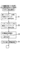
図4は、パチンコ機Pの主制御基板Cにおいて実行されるメイン処理のフローチャートである。パチンコ機Pの主な制御は、このメイン処理によって実行される。メイン処理では、まず、割込を禁止した後(S11)、図5に示す初期化処理を実行する(S12)。 FIG. 4 is a flowchart of a main process executed on the main control board C of the pachinko machine P. The main control of the pachinko machine P is executed by this main process. In the main process, interrupts are first prohibited (S11), and then the initialization process shown in FIG. 5 is executed (S12).
図5は、パチンコ機Pの電源入時に主制御基板Cのメイン処理の中で実行される初期化処理(S12)のフローチャートである。この処理では、バックアップが有効であれば、バックアップエリア13aに記憶された各データを元の状態に戻し、遊技の制御を電源が断される前の状態から続行する。一方、バックアップが有効でなかったり、或いは、バックアップが有効であっても電源入時にクリアスイッチ50cが押下された場合には、RAMクリア及び初期化処理を実行する。なお、この初期化処理(S12)は、サブルーチンの形式で記載されているが、スタックポインタの設定前に実行される処理なので、実際には、サブルーチンコールされずに、S11の処理後に順に実行される。
FIG. 5 is a flowchart of the initialization process (S12) executed in the main process of the main control board C when the pachinko machine P is turned on. In this process, if the backup is valid, each data stored in the backup area 13a is returned to the original state, and the game control is continued from the state before the power is turned off. On the other hand, if the backup is not valid, or if the
まず、スタックポインタを設定し(S41)、次に、クリアスイッチ50cがオンされているか否かを確認する(S42)。クリアスイッチ50cがオンされていなければ(S42:No)、バックアップが有効であるか否かを確認する(S43)。この確認は、RAM13の所定のエリアに書き込まれたキーワードが正しく記憶されているか否かにより判断する。キーワードが正しく記憶されていればバックアップは有効であり、逆に、キーワードが正しくなければバックアップデータは破壊されているので、そのバックアップは有効ではない。バックアップが有効であれば(S43:Yes)、処理をS46へ移行して、動作タイミング調整処理(図6参照)の実行し、その後、主制御基板Cの各状態を電源断前の状態に復帰させる。一方、バックアップが有効でなかったり(S43:No)、或いはクリアスイッチ50cがオンされていれば(S42:Yes)、RAMクリア及び初期化処理を実行して(S44)、RAM13及びI/O等の各値を初期化し、動作タイミング調整処理(図6参照)を実行して、この初期化処理を終了する。S45の処理の終了後は、図4のS13の処理が実行される。
First, a stack pointer is set (S41), and then it is confirmed whether or not the
なお、動作タイミング調整処理(S45,S46)は、各制御基板C,H,B,D,Sが立ち上げ処理の終了後に遊技の制御を開始するタイミングが略同一となるように、そのタイミングを調整するための処理である。詳細については、図6を参照しつつ後述する。 Note that the operation timing adjustment processing (S45, S46) is performed so that the timings at which the control boards C, H, B, D, and S start the game control after the start-up processing is almost the same. This is a process for adjustment. Details will be described later with reference to FIG.
S46からの処理では、まず、動作タイミング調整処理を実行し(S46)、次にバックアップエリア13aからスタックポインタの値を読み出して、これをスタックポインタへ書き込み、電源断前(停電前)の状態、即ちNMI割込発生前の状態に戻す(S47)。その後、スタックポインタの値を戻した後のスタックエリア、即ちバックアップエリア13aへ退避した各レジスタやI/O等のデータをそのバックアップエリア13aから読み出して、これら各データを元のレジスタやI/O等へ書き込む(S48)。更に、割込状態を停電発生時に実行される図3の処理で記憶しておいた電源断前(停電前)の状態、即ちNMI割込発生前の状態に戻し(S49)、NMI割込リターンを実行して、処理を電源断前に実行していたところへ戻して、制御を電源断前の状態から続行する。 In the process from S46, first, the operation timing adjustment process is executed (S46), and then the value of the stack pointer is read from the backup area 13a and written to the stack pointer. That is, the state before the occurrence of the NMI interrupt is restored (S47). Thereafter, the stack area after returning the value of the stack pointer, that is, data such as each register and I / O saved in the backup area 13a is read from the backup area 13a, and these data are read from the original register and I / O. Etc. (S48). Further, the interrupt state is returned to the state before the power interruption (before the power failure) stored in the process of FIG. 3 executed at the time of the power failure, that is, the state before the NMI interrupt is generated (S49), and the NMI interrupt return. To return to the place where the processing was executed before the power was turned off, and the control is continued from the state before the power was turned off.
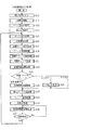
図4のフローチャートの戻って説明する。S13の処理ではタイマ割込の設定を行う(S13)。ここで設定されるタイマ割込としては、各制御基板H,D,Sへコマンドを送信するためのストローブ信号を発生させるタイマ割込などがある。タイマ割込の設定後は、各割込を許可状態とする(S14)。割込の許可後は、特別図柄変動処理(S25)や、表示データ作成処理(S27)、ランプ・情報処理(S28)などにより、前回の処理で更新された出力データを一度に各ポートへ出力するポート出力処理を実行する(S15)。 Returning to the flowchart of FIG. In the process of S13, a timer interrupt is set (S13). Examples of the timer interrupt set here include a timer interrupt that generates a strobe signal for transmitting a command to each control board H, D, and S. After setting the timer interrupt, each interrupt is permitted (S14). After the interruption is permitted, the output data updated in the previous process is output to each port at once by the special symbol variation process (S25), display data creation process (S27), ramp / information processing (S28), etc. The port output process is executed (S15).
更に、大当たりを決定するための乱数カウンタの値などを「+1」更新する乱数更新処理(S16)を実行し、記憶タイマ減算処理を実行する(S17)。記憶タイマ減算処理は、大当たり判定の保留球が所定数以上あり、且つ、LCD3において図柄の変動表示中である場合に、図柄の変動表示の時間短縮を行うものである。
Further, a random number update process (S16) for updating the value of the random number counter for determining the jackpot by “+1” is executed, and a storage timer subtraction process is executed (S17). The storage timer subtraction process shortens the time for symbol variation display when there is a predetermined number or more of reserved balls for jackpot determination and the symbol variation display is being performed on the
スイッチ監視処理(S18)は、INT割込で読み込まれた各スイッチの状態に応じて、遊技領域へ打ち込まれた球の入賞口2や大入賞口5、図柄作動口4への入賞、球のゲート7の通過、更には賞球の払い出し等に関する処理を行うものである。図柄カウンタ更新処理(S20)では、LCD3で行われる変動表示の結果、停止表示される図柄を決定するためのカウンタの更新処理が行われる。また、図柄チェック処理(S21)では、図柄カウンタ更新処理(S20)で更新されたカウンタの値に基づいて、特別図柄変動処理(S25)で使用される大当たり図柄や、はずれ図柄、更にはリーチ図柄などが決定される。
In the switch monitoring process (S18), according to the state of each switch read by the INT interrupt, a ball that has been driven into the game area is awarded to the winning
その後、普通図柄変動処理(S23)によって、普通図柄としての「○」及び「×」のLED6a,6bの変動表示を行うと共に、その変動表示の結果、大当たりが発生した場合には普通電動役物(第1種図柄作動口4)を所定時間開放する大当たり処理を実行する。その後、状態フラグをチェックし(S24)、LCD3において特別図柄の変動開始または変動表示中であれば(S24:図柄変動中)、特別図柄変動処理(S25)によって、球が図柄作動口4を通過するタイミングで読み取った乱数カウンタの値に基づいて、大当たりか否かの判定が行われると共に、LCD3にて特別図柄の変動処理を実行する。一方、状態フラグをチェックした結果、大当たり中であれば(S24:大当り中)、大入賞口5を開放するなどの大当たり処理(S26)を実行する。更に、状態フラグをチェックした結果、図柄の変動中でも大当たり中でもなければ(S24:その他)、S25及びS26の処理をスキップして、S27の表示データ作成処理へ移行する。
After that, the normal symbol variation process (S23) displays the variation of the “O” and “X”
表示データ作成処理(S27)では、図柄の変動表示以外にLCD3に表示されるデモデータや、「○」及び「×」のLED6a,6bの表示データなどが作成され、ランプ・情報処理(S28)では、保留球のランプデータをはじめ、各種のランプデータが作成される。効果音処理(S29)では、遊技の状況に応じた効果音データが作成される。なお、これらの表示データ及び効果音データは、前記したポート出力処理(S15)やタイマ割込処理によって各制御基板H,D,Sへ出力される。
In the display data creation process (S27), the demo data displayed on the
効果音処理(S29)の終了後は、次のS15の処理の実行タイミングが到来するまでの残余時間の間、大当たりを決定するための乱数カウンタの初期値を更新する乱数初期値更新処理(S30)を繰り返し実行する。S15〜S29の各処理は定期的に実行する必要があるので、S31の処理において、前回のS15の処理の実行からの経過時間をチェックする(S31)。チェックの結果、前回のS15の処理の実行から所定時間経過していれば(S31:Yes)、処理をS15へ移行し、一方、所定時間経過していなければ(S31:No)、処理をS30へ移行して、乱数初期値更新処理(S30)の実行を繰り返す。ここで、S15〜S29の各処理の実行時間は、遊技の状態に応じて変化するので、次のS15の処理の実行タイミングが到来するまでの残余時間は、一定の時間ではない。よって、かかる残余時間を使用して乱数初期値更新処理(S30)を繰り返し実行することにより、乱数カウンタの初期値をランダムに更新することができる。 After the end of the sound effect process (S29), the random number initial value update process (S30) for updating the initial value of the random number counter for determining the jackpot during the remaining time until the next execution timing of the process of S15 comes. ) Repeatedly. Since each process of S15 to S29 needs to be executed periodically, in the process of S31, an elapsed time from the previous execution of the process of S15 is checked (S31). As a result of the check, if a predetermined time has elapsed since the previous execution of the process of S15 (S31: Yes), the process proceeds to S15. On the other hand, if the predetermined time has not elapsed (S31: No), the process proceeds to S30. And the execution of the random number initial value update process (S30) is repeated. Here, since the execution time of each process of S15-S29 changes according to the state of a game, the remaining time until the next execution timing of the process of S15 comes is not a fixed time. Therefore, the initial value of the random number counter can be updated at random by repeatedly executing the random number initial value update process (S30) using the remaining time.
図6は、パチンコ機Pの主制御基板Cにおいて、図4の初期化処理の中で実行される動作タイミング調整処理(S45,S46)のフローチャートである。動作タイミング調整処理は、主制御基板Cを含めた各制御基板(払出制御基板H、発射制御基板B、表示用制御基板D、音声ランプ制御基板S)について、立ち上げ処理の終了後の動作の開始タイミングを調整するものである。 FIG. 6 is a flowchart of the operation timing adjustment process (S45, S46) executed in the initialization process of FIG. 4 on the main control board C of the pachinko machine P. The operation timing adjustment process is performed for each control board including the main control board C (the payout control board H, the launch control board B, the display control board D, and the sound lamp control board S) after the start-up process is completed. The start timing is adjusted.
まず、球経路封鎖ソレノイド9aをオンして(S51)、弁体9bを球経路8へ突出させて球経路を封鎖する。これにより、球経路8へ突出された弁体9bによって、各制御基板C,H,B,D,Sが動作を開始する前に、球が遊技領域へ打ち込まれることを確実に防止することができる。
First, the ball
弁体9bによる球経路8の封鎖後、第1ウエイト処理を実行し(S52)、その後、各制御基板(払出制御基板H、表示用制御基板D、音声ランプ制御基板S)へ動作許可コマンドを送信する(S53)。各制御基板H,D,Sは、この動作許可コマンドを受信すると、立ち上げ処理を完了して、遊技の制御を開始する。なお、発射制御基板Bへは、動作許可コマンドを受信した払出制御基板Hから発射許可信号が出力される(図7のS67,S71参照)。ここで、第1ウエイト処理によって、第1の所定時間、処理の進行がウエイトされる。第1の所定時間は、立ち上げ時間の最も遅い制御基板C,H,D,Sの立ち上げ時間に基づいて設定される。即ち、主制御基板Cが第1ウエイト処理(S52)の実行を完了したときには、確実にすべての制御基板C,H,D,Sの立ち上げ処理が終了して遊技の制御を即座に開始できるように、第1の所定時間が設定される。
After the
パチンコ機Pの各制御基板C,H,B,D,Sは、機種変更される毎に各種機能が追加されるので、その影響で各機種毎または各制御基板毎に立ち上げ処理に要する時間はそれぞれ異なる。パチンコ機Pの遊技は各制御基板C,H,B,D,Sでそれぞれ分担して制御されるので、制御の開始タイミングを調整して、各制御基板C,H,B,D,Sが一斉に遊技の制御を開始できるようにすることが望ましい。その際、各制御基板C,H,B,D,Sで双方向に立ち上げ処理の完了を確認し合って、すべての制御基板C,H,B,D,Sが立ち上げ処理を完了したことを確認した上で遊技の制御を開始するように構成することも考えられるが、制御が極めて煩雑となる。 Each control board C, H, B, D, and S of the pachinko machine P is added with various functions every time the model is changed. Therefore, the time required for start-up processing for each model or each control board is affected by the function. Are different. Since the game of the pachinko machine P is controlled by the control boards C, H, B, D, and S, the control start timing is adjusted so that the control boards C, H, B, D, and S It is desirable to be able to start game control all at once. At that time, each control board C, H, B, D, S confirmed the completion of the startup process in both directions, and all the control boards C, H, B, D, S completed the startup process. It can be considered that the game control is started after confirming this, but the control becomes extremely complicated.
これに対し、本実施例では、立ち上げ時間の最も遅い制御基板C,H,D,Sの立ち上げ時間に基づいて第1の所定時間を設定し、その所定時間のウエイト後、主制御基板Cから各制御基板H,D,Sへ動作許可コマンドを送信して遊技の制御を各制御基板C,H,D,Sで一斉に開始するように構成している。よって、簡略化したプログラムで制御の開始タイミングを調整することができる。また、設計変更などにより一部の制御基板の立ち上げ時間が変わった場合にも、その変更された制御基板に合わせて、主制御基板Cの第1ウエイト処理の第1の所定時間を変更することにより容易に対応することができるので、優れた汎用性をも備えている。なお、本実施例では、ウエイト処理はソフトタイマにより計時している。しかし、ソフトタイマに代えて、MPU11に内蔵されるタイマやフリーランニングカウンタ等を使用して第1の所定時間を計時するようにしても良い。
On the other hand, in this embodiment, the first predetermined time is set based on the startup time of the control boards C, H, D, and S having the latest startup time, and after waiting for the predetermined time, the main control board is set. An operation permission command is transmitted from C to each of the control boards H, D, and S, and control of the game is started simultaneously on each of the control boards C, H, D, and S. Therefore, the control start timing can be adjusted with a simplified program. Further, even when the startup time of some control boards changes due to a design change or the like, the first predetermined time of the first wait process of the main control board C is changed in accordance with the changed control boards. Since it can respond easily, it has the outstanding versatility. In this embodiment, the wait process is timed by a soft timer. However, the first predetermined time may be measured using a timer, a free running counter, or the like built in the
各制御基板H,D,Sへの動作許可コマンドの送信後、第2ウエイト処理を実行して(S54)、第2の所定時間ウエイトする。その後、球経路封鎖ソレノイド9aをオフして(S55)、弁体9bを球経路8から戻し、球経路8の封鎖を解除した上で、この動作タイミング調整処理を終了する。第2ウエイト処理は、動作許可コマンドを受信した各制御基板H,D,Sが実際に遊技の制御を開始するまでの時間を考慮して設けられている。発射制御基板Bは、MPUを有さないロジック回路により構成されているので、動作許可コマンドを受信した払出制御基板Hから出力される発射許可信号を入力すると、他の制御基板H,D,Sに比べて非常に短時間のうちに発射用モータ28を発射可能な状態とする。よって、動作許可コマンドを受信した各制御基板H,D,Sが遊技の制御を開始する前に球が遊技領域へ打ち込まれないように、第2ウエイト処理を設けて、球経路8の封鎖の解除を若干時間遅らせているのである。
After the operation permission command is transmitted to each of the control boards H, D, and S, the second wait process is executed (S54) and waits for a second predetermined time. Thereafter, the ball
図7は、払出制御基板Hのメイン処理のフローチャートである。このメイン処理では、まず、スタックポインタを設定し(S61)、次に、発射制御基板Bへ出力される発射許可信号をオフして(S62)、球の発射を禁止する。クリアスイッチ50cがオンされているか否かを確認し(S63)、オンされていなければ(S63:No)、バックアップが有効であるか否かを確認する(S64)。この確認は、RAM23の所定のエリアに書き込まれたキーワードが正しく記憶されているか否かにより判断する。キーワードが正しく記憶されていればバックアップは有効であり、逆に、キーワードが正しくなければバックアップデータは破壊されているので、そのバックアップは有効ではない。バックアップが有効であれば(S64:Yes)、処理をS70へ移行して、主制御基板Cから送信される動作許可コマンドの受信を待機する。
FIG. 7 is a flowchart of the main process of the payout control board H. In this main process, first, the stack pointer is set (S61), and then the launch permission signal output to the launch control board B is turned off (S62) to prohibit the launch of the ball. It is confirmed whether or not the
一方、バックアップが有効でなかったり(S64:No)、或いはクリアスイッチ50cがオンされていれば(S63:Yes)、RAMクリア及び初期化処理を実行して(S65)、RAM23及びI/O等の各値を初期化し、払出制御基板Hの立ち上げ処理を終了する。
On the other hand, if the backup is not valid (S64: No) or the
その後、主制御基板Cから送信される動作許可コマンドを受信するまで制御の進行を待機し(S66:No)、動作許可コマンドを受信すれば(S66:Yes)、制御の進行を開始する。具体的には、発射制御基板Bへ発射許可信号を出力した後(S67)、割込を許可して(S68)、払出制御基板Hのメイン処理で実行される各処理を実行し(S69)、この各処理を繰り返す。これにより、払出制御基板Hは、立ち上げ処理後の制御の進行タイミングを主制御基板Cのタイミングに合わせることができる。なお、発射許可信号は、球の発射を禁止する状態とならない限り、払出制御基板Hから発射制御基板Bへ出力され続ける。即ち、発射制御基板Bは、払出制御基板Hから発射許可信号が出力されていなければ、発射用モータ28を発射可能な状態にすることはできない。 Thereafter, the control waits until the operation permission command transmitted from the main control board C is received (S66: No). If the operation permission command is received (S66: Yes), the control starts. Specifically, after outputting the firing permission signal to the firing control board B (S67), the interruption is permitted (S68), and each process executed in the main process of the payout control board H is executed (S69). Each of these processes is repeated. Thereby, the payout control board H can match the progress timing of the control after the start-up process with the timing of the main control board C. It should be noted that the launch permission signal continues to be output from the payout control board H to the launch control board B unless the launch of the ball is prohibited. In other words, if the firing control board B does not output a firing permission signal from the payout control board H, the firing motor 28 cannot make the firing motor 28 ready to fire.
S70からの処理では、まず、主制御基板Cから送信される動作許可コマンドを受信するまで制御の進行を待機する(S70:No)。そして、動作許可コマンドを受信すれば(S70:Yes)、制御の進行を開始する。具体的には、発射制御基板Bへ発射許可信号を出力した後(S71)、バックアップエリア23aからスタックポインタの値を読み出して、これをスタックポインタへ書き込み、電源断前(停電前)の状態、即ちNMI割込発生前の状態に戻す(S72)。その後、スタックポインタの値を戻した後のスタックエリア、即ちバックアップエリア23aへ退避した各レジスタやI/O等のデータをそのバックアップエリア23aから読み出して、これら各データを元のレジスタやI/O等へ書き込む(S73)。更に、割込状態を停電発生時に実行される図3の処理で記憶しておいた電源断前(停電前)の状態、即ちNMI割込発生前の状態に戻し(S74)、NMI割込リターンを実行して、処理を電源断前に実行していたところへ戻して、制御を電源断前の状態から続行する。このように、バックアップが有効な場合にも、払出制御基板Hは、立ち上げ処理後の制御の進行タイミングを主制御基板Cのタイミングに合わせることができる。 In the processing from S70, firstly, the control waits until the operation permission command transmitted from the main control board C is received (S70: No). If the operation permission command is received (S70: Yes), the control starts. Specifically, after outputting a firing permission signal to the firing control board B (S71), the value of the stack pointer is read from the backup area 23a and written to the stack pointer, before power is turned off (before power failure), That is, the state before the occurrence of the NMI interrupt is restored (S72). After that, the stack area after returning the value of the stack pointer, that is, data such as each register and I / O saved in the backup area 23a is read from the backup area 23a, and each data is read from the original register and I / O. Etc. (S73). Further, the interrupt state is returned to the state before the power interruption (before the power failure) stored in the processing of FIG. 3 executed at the time of the power failure, that is, the state before the NMI interrupt is generated (S74), and the NMI interrupt return. To return to the place where the processing was executed before the power was turned off, and the control is continued from the state before the power was turned off. Thus, even when the backup is valid, the payout control board H can match the progress timing of the control after the start-up process with the timing of the main control board C.
図8は、表示用制御基板Dのメイン処理のフローチャートである。このメイン処理では、まず、立ち上げ処理としての初期化処理を実行して(S81)、LCD3の表示画面に文字などを表示可能な状態としてから、そのLCD3画面に「しばらくお待ち下さい」と表示する(S82)。かかる表示をしたまま、主制御基板Cから送信される動作許可コマンドを受信するまで制御の進行を待機する(S83:No)。そして、動作許可コマンドを受信すれば(S83:Yes)、表示用制御基板Dのメイン処理で実行される各処理を実行し(S84)、この各処理を繰り返す。
FIG. 8 is a flowchart of the main process of the display control board D. In this main process, first, an initialization process as a start-up process is executed (S81), a character or the like can be displayed on the display screen of the
これにより、表示用制御基板Dは、立ち上げ処理後の制御の進行タイミングを主制御基板Cのタイミングに合わせることができる。しかも、待機期間中、LCD3の表示画面には所定の待機メッセージが表示されるので、電源を投入から遊技が開始できるようになるまでに長時間かかっても、使用者にパチンコ機Pの故障などの不安を抱かせることなく、パチンコ機P全体の立ち上げ処理を待機させることができる。
Thereby, the display control board D can match the control progress timing after the start-up process with the timing of the main control board C. Moreover, since a predetermined standby message is displayed on the display screen of the
以上説明したように、本実施例のパチンコ機Pによれば、電源投入後、主制御基板Cで各副制御基板(各サブ制御基板)H,D,Sが立ち上げ処理を完了するのに十分な第1の所定時間ウエイトする第1ウエイト処理を実行した後、各副制御基板(払出制御基板H、表示用制御基板D、音声ランプ制御基板S)へそれぞれ動作許可コマンドを送信するように構成されている。また、各副制御基板H,D,Sは、かかる動作許可コマンドを受信するまでは、立ち上げ処理の後の制御の進行を待機し、該動作許可コマンドを受信した後に、立ち上げ処理の後の制御を開始するように構成されている。よって、煩雑な制御を用いることなく、主制御基板Cと各副制御基板H,D,Sとの立ち上げ処理後の動作タイミングを略同一タイミングに調整することができる。 As described above, according to the pachinko machine P of this embodiment, after the power is turned on, each sub control board (each sub control board) H, D, S completes the start-up process on the main control board C. After executing a first wait process that waits for a sufficient first predetermined time, an operation permission command is transmitted to each sub-control board (payout control board H, display control board D, sound lamp control board S). It is configured. Each sub-control board H, D, S waits for the progress of the control after the startup process until such an operation permission command is received, and after receiving the operation permission command, It is configured to start control. Therefore, the operation timing after the start-up process of the main control board C and each of the sub control boards H, D, S can be adjusted to substantially the same timing without using complicated control.
主制御基板Cおよび各副制御基板H,D,Sの立ち上げ時間(初期化処理が終了するまでの時間)は、副制御基板H,D,Sの種類によっても異なるし、副制御基板H,D,Sの種類が同じであってもパチンコ機Pの機種毎に異なる。かかる場合、パチンコ機Pの立ち上げをスムースに行うためには、主制御基板Cと副制御基板H,D,Sとの間で立ち上げタイミングを調整する必要がある。この調整方式としては、各制御基板C,H,D,Sは自己の立ち上げ処理が完了した場合に、その旨を互いに通信し合い、すべての制御基板C,H,D,Sの立ち上げ処理が終了したことが確認された後に、それぞれ制御を進行させる方式が考えられる。しかしながら、かかる調整方式によれば、各制御基板C,H,D,Sを互いに双方向通信可能に構成しなければならない。また、制御基板の数が多くなると、立ち上げタイミングの調整処理が非常に煩雑なものとなってしまう。更に、立ち上げ処理の終了した制御基板から出力される立ち上げ完了信号を、立ち上げ処理中の制御基板で入力できるように制御を構成しなければならず、制御が極めて煩雑になる。 The startup time of the main control board C and each of the sub control boards H, D, S (time until the initialization process is completed) varies depending on the types of the sub control boards H, D, S, and the sub control board H , D, and S are different for each model of the pachinko machine P even if the types are the same. In such a case, in order to smoothly start up the pachinko machine P, it is necessary to adjust the start-up timing between the main control board C and the sub-control boards H, D, S. As this adjustment method, when each control board C, H, D, S completes its own start-up process, it communicates to that effect, and all control boards C, H, D, S start up. A method of proceeding control after confirming that the processing is completed can be considered. However, according to such an adjustment method, the control boards C, H, D, and S must be configured to be capable of bidirectional communication with each other. Further, when the number of control boards increases, the startup timing adjustment process becomes very complicated. Furthermore, the control must be configured so that the start-up completion signal output from the control board that has completed the start-up process can be input to the control board during the start-up process, which makes control extremely complicated.
また、副制御基板H,D,Sは、主に主制御基板Cから送信されるコマンドにより制御されるので、副制御基板H,D,Sを主制御基板Cより先に立ち上げれば、副制御基板H,D,Sは主制御基板Cの立ち上げ処理終了後に送信されるコマンドを待機することとなるので、該コマンドを確実に受信でき、その結果、主制御基板Cと副制御基板H,D,Sとの動作タイミングを調整することができ、制御を円滑に開始できる。言い換えれば、主制御基板Cを副制御基板H,D,Sの後に立ち上げ終了させるのである。 Further, since the sub control boards H, D, and S are controlled mainly by commands transmitted from the main control board C, if the sub control boards H, D, and S are started before the main control board C, the sub control boards H, D, and S are controlled. Since the control boards H, D, and S wait for a command to be transmitted after the start-up process of the main control board C is completed, the command can be reliably received. As a result, the main control board C and the sub-control board H can be received. , D and S can be adjusted, and control can be started smoothly. In other words, the start-up of the main control board C is terminated after the sub-control boards H, D, S.
このためにパチンコ機Pの電源投入時に各制御基板C,H,D,Sへ出力されるリセット信号を、主制御基板Cに対してはハード的に遅延させる遅延回路を設けて、主制御基板Cへのリセット信号の入力タイミングを副制御基板H,D,Sへのリセット信号の入力タイミングより遅延させて、主制御基板Cの立ち上げ処理の実行開始を副制御基板H,D,Sより遅らせることにより、主制御基板Cを副制御基板H,D,Sの後に立ち上げ終了させることも考えられる。しかしながら、近年のLCD3の大型化等に代表されるように、パチンコ機Pの各パーツを制御する副制御基板H,D,Sの負担が増大する傾向にある。このため副制御基板H,D,Sの立ち上げ時間は増大する傾向にあり、ハード的な遅延回路だけでは対応しきれない。また、副制御基板H,D,Sは、パチンコ機Pの制御を分担するように構成されているので、副制御基板H,D,Sを個別に取り替えて異なる機種を構成することもある。かかる場合には、パチンコ機Pを構成する主制御基板Cと副制御基板H,D,Sとの組み合わせが異なるので、その組み合わせに応じてそれぞれ遅延回路を設計しなければならず、ハード的な遅延回路だけでは対応しきれない。
For this purpose, a delay circuit is provided for delaying the reset signal output to each control board C, H, D, S when the power of the pachinko machine P is turned on to the main control board C in a hardware manner. The start timing of the start-up process of the main control board C is started from the sub control boards H, D, S by delaying the input timing of the reset signal to C from the input timing of the reset signal to the sub control boards H, D, S. It is also conceivable that the start-up of the main control board C after the sub-control boards H, D, S is terminated by delaying. However, as represented by the recent increase in size of the
これに対し、本実施例のパチンコ機Pでは、主制御基板Cで所定時間のウエイト処理を実行した後、副制御基板H,D,Sへ動作許可を出力するように構成されているので、煩雑な制御やハード的な遅延回路だけを用いることなく、主制御基板Cと副制御基板H,D,Sとの動作タイミングを容易に調整することができる。ウエイト時間の調整は容易に行い得るからである。なお、本実施例の構成にハード的な遅延回路を併設しても良い。 On the other hand, the pachinko machine P according to the present embodiment is configured to output an operation permission to the sub control boards H, D, S after executing a wait process for a predetermined time on the main control board C. The operation timings of the main control board C and the sub control boards H, D, and S can be easily adjusted without using only complicated control and hardware delay circuits. This is because the weight time can be easily adjusted. A hardware delay circuit may be added to the configuration of this embodiment.
なお、本実施例における請求項1記載の計時手段としては、動作タイミング調整処理(図6)の中で実行される第1ウエイト処理(S52)が該当する。
Note that the timing means described in
以上、実施例に基づき本発明を説明したが、本発明は上記実施例に何ら限定されるものではなく、本発明の趣旨を逸脱しない範囲内で種々の改良変形が可能であることは容易に推察できるものである。 The present invention has been described based on the embodiments. However, the present invention is not limited to the above-described embodiments, and various improvements and modifications can be easily made without departing from the spirit of the present invention. It can be guessed.
上記実施例のS45およびS46の動作タイミング調整処理では、第1ウエイト処理(S51)によって、いずれも第1の所定時間ウエイトされたが、S45の動作タイミング調整処理における第1ウエイト処理のウエイト時間と、S46の処理における第1ウエイト処理のウエイト時間とを異なる時間としても良い。即ち、S45の動作タイミング調整処理はRAMクリア及び初期化処理(S44)の後に実行されるので、そのS44の処理の時間分、S46の動作タイミング調整処理での第1ウエイト処理のウエイト時間を短縮するようにしても良い。 In the operation timing adjustment process of S45 and S46 in the above-described embodiment, the first wait process (S51) has waited for the first predetermined time, but the wait time of the first wait process in the operation timing adjustment process of S45 The wait time of the first wait process in the process of S46 may be a different time. That is, since the operation timing adjustment process of S45 is executed after the RAM clear and initialization process (S44), the wait time of the first wait process in the operation timing adjustment process of S46 is shortened by the time of the process of S44. You may make it do.
また、上記実施例では、各制御基板C,H,D,Sの立ち上げ処理中に、球が遊技領域へ発射されることを防止するため、球経路8を封鎖する封鎖弁9を設けると共に、発射用モータ28は払出制御基板Hから発射制御基板Bへ発射許可信号が出力されていなければ発射不可能に構成した。しかし、必ずしも両者の構成を1のパチンコ機Pに同時に設ける必要はなく、いずれか一方の構成のみを設けて、各制御基板C,H,D,Sの立ち上げ処理中に、球が遊技領域へ発射されることを防止するようにしても良い。なお、払出制御基板Hから発射制御基板Bへ発射許可信号が一旦出力されれば、次に、発射禁止信号が出力されるまで、発射許可信号の出力状態に拘わらず、発射用モータ28を発射可能な状態にするように構成しても良い。
In the above embodiment, a blocking
更に、各制御基板C,H,D,Sの立ち上げ処理が終了するまでの間は、発射制御基板B又は発射用モータ28への電源供給を止めて、遊技領域へ球が発射されないようにしても良い。封鎖弁9により遊技領域への球の発射を止める場合(発射許可信号は使用しない場合)、発射した球は遊技領域へ打ち込まれないものの、球の発射はできてしまうので、使用者に故障などを思惑させ好ましくない。これに対し、発射制御基板B又は発射用モータ28への電源供給を止めるように構成すれば発射自体が行われないので、遊技者に違和感を与えることなく、遊技領域への球の発射を止めることができる。なお、封鎖弁9により遊技領域への球の発射を止める方式と、この発射制御基板B又は発射用モータ28への電源供給を止めて遊技領域への球の発射を止める方式とを、1台のパチンコ機に併設しても良い。
Further, until the start-up process of each control board C, H, D, S is completed, the power supply to the launch control board B or the launch motor 28 is stopped so that the ball is not launched into the game area. May be. When stopping the ball launching into the game area by the blockade valve 9 (when the firing permission signal is not used), the fired ball will not be driven into the game area, but the ball can be fired, so the user will be out of order. This is not desirable. On the other hand, if the power supply to the launch control board B or the launch motor 28 is stopped, the launch itself is not performed, so the launch of the ball to the game area is stopped without giving the player a sense of incongruity. be able to. In addition, there is one system that stops the ball launching to the game area by the blocking
発射制御基板Bと払出用制御基板Hとは別個に構成されたが、発射制御基板Bを払出制御基板Hに内蔵して(或いはその逆にして)、両制御基板B,Hを1の制御基板で構成しても良い。かかる構成によれば、払出制御基板Hから発射制御基板Bへ出力されていた発射許可信号(図7のS62,S67,S71)が不要となり、その分、制御を簡略化することができる。 The launch control board B and the payout control board H are configured separately, but the launch control board B is built in the payout control board H (or vice versa), and both control boards B and H are controlled by one. You may comprise with a board | substrate. According to such a configuration, the firing permission signal (S62, S67, S71 in FIG. 7) output from the payout control board H to the firing control board B becomes unnecessary, and the control can be simplified correspondingly.
球経路封鎖ソレノイド9aを自己保持型ソレノイドであるキープソレノイドで構成しても良い。キープソレノイドは、従来型のオープンフレームソレノイドに高性能な永久磁石を組み合わせたものである。コイルに瞬時(1パルス)の通電を加えると、プランジャがシャフトを吸引し、吸引後は永久磁石によりシャフトを吸着保持するので、この間の通電を不要にした省エネルギータイプのソレノイドである。このキープソレノイドを球経路封鎖ソレノイド9aに用いることにより、電源基板50の寿命延長や球経路封鎖ソレノイド9a自体の発熱を少なくすることができる。
The ball
本発明を上記実施例とは異なるタイプのパチンコ機等に実施しても良い。例えば、一度大当たりすると、それを含めて複数回(例えば2回、3回)大当たり状態が発生するまで、大当たり期待値が高められるようなパチンコ機(通称、2回権利物、3回権利物と称される)として実施しても良い。また、大当たり図柄が表示された後に、所定の領域に球を入賞させることを必要条件として特別遊技状態となるパチンコ機として実施しても良い。更に、パチンコ機以外にも、アレパチ、雀球、スロットマシン、いわゆるパチンコ機とスロットマシンとが融合した遊技機などの各種遊技機として実施するようにしても良い。 You may implement this invention in the pachinko machine etc. of a different type from the said Example. For example, once a big hit, a pachinko machine (commonly known as a two-time right, a three-time right, etc.) that increases the expected value of the big hit until a big hit state occurs (for example, twice or three times). May also be implemented. Moreover, after the jackpot symbol is displayed, it may be implemented as a pachinko machine that enters a special game state on the condition that a ball is awarded in a predetermined area. Further, in addition to the pachinko machine, the game machine may be implemented as various game machines such as an alepatchi, a sparrow ball, a slot machine, a game machine in which a so-called pachinko machine and a slot machine are integrated.
なお、スロットマシンは、例えばコインを投入して図柄有効ラインを決定させた状態で操作レバーを操作することにより図柄が変動され、ストップボタンを操作することにより図柄が停止されて確定される周知のものである。従って、スロットマシンの基本概念としては、「複数の図柄からなる図柄列を変動表示した後に図柄を確定表示する可変表示手段を備え、始動用操作手段(例えば操作レバー)の操作に起因して図柄の変動が開始され、停止用操作手段(例えばストップボタン)の操作に起因して、或いは、所定時間経過することにより、図柄の変動が停止され、その停止時の確定図柄が特定図柄であることを必要条件として、遊技者に有利な特別遊技状態を発生させる特別遊技状態発生手段とを備えたスロットマシン」となり、この場合、遊技媒体はコイン、メダル等が代表例として挙げられる。 In the slot machine, for example, a symbol is changed by operating a control lever in a state where a symbol effective line is determined by inserting coins, and a symbol is stopped and confirmed by operating a stop button. Is. Therefore, the basic concept of the slot machine is that “a variable display means for confirming and displaying a symbol after a symbol string composed of a plurality of symbols is displayed in a variable manner, and the symbol resulting from the operation of the starting operation means (for example, an operating lever). The change of the symbol is stopped due to the operation of the operation means for stopping (for example, the stop button) or after a predetermined time has elapsed, and the fixed symbol at the time of the stop is a specific symbol Is a slot machine provided with a special game state generating means for generating a special game state advantageous to the player. In this case, the game medium is typically a coin, a medal or the like.
また、パチンコ機とスロットマシンとが融合した遊技機の具体例としては、複数の図柄からなる図柄列を変動表示した後に図柄を確定表示する可変表示手段を備えており、球打出用のハンドルを備えていないものが挙げられる。この場合、所定の操作(ボタン操作)に基づく所定量の球の投入の後、例えば操作レバーの操作に起因して図柄の変動が開始され、例えばストップボタンの操作に起因して、或いは、所定時間経過することにより、図柄の変動が停止され、その停止時の確定図柄がいわゆる大当たり図柄であることを必要条件として遊技者に有利な大当たり状態が発生させられ、遊技者には、下部の受皿に多量の球が払い出されるものである。 In addition, as a specific example of a gaming machine in which a pachinko machine and a slot machine are integrated, a variable display means for displaying a symbol after a symbol string composed of a plurality of symbols is displayed, and a handle for launching a ball is provided. What is not provided. In this case, after throwing a predetermined amount of spheres based on a predetermined operation (button operation), for example, the change of the symbol is started due to the operation of the operation lever, for example, due to the operation of the stop button, or With the passage of time, the fluctuation of the symbol is stopped, and a jackpot state advantageous to the player is generated on the condition that the confirmed symbol at the time of stoppage is a so-called jackpot symbol. A lot of balls are paid out.
以下に本発明の変形例を示す。遊技の制御を行う主制御手段と、その主制御手段から出力されるコマンドに基づいて遊技に関する制御を行う副制御手段とを備えた遊技機において、前記副制御手段は、前記主制御手段からの動作許可を入力するまで制御の進行を待機するものであることを特徴とする遊技機1。パチンコ機の遊技の制御は、主に主制御手段により行われる。この主制御手段には、賞球や貸し球の払い出し制御を行う払出制御手段や、効果音の出力制御やランプの点灯制御を行う音声ランプ制御手段、図柄の変動表示等の表示制御を行う表示用制御手段などの副制御手段が接続されている。これら副制御手段は、主に主制御手段から送信されるコマンドにより制御される。各制御手段は、パチンコ機の電源が投入されると、それぞれ独自に立ち上げ処理(初期化処理)を行う。この立ち上げ処理が完了してはじめて、遊技の制御を進行することができる。しかしながら、立ち上げ処理に要する時間は各制御手段で区々なので、立ち上げ処理が早く終了する制御手段は、他の制御手段の立ち上げ処理が終了する前に制御を始めることとなり、誤動作の原因となる。遊技機1によれば、副制御手段は主制御手段からの動作許可を入力するまで制御の進行を待機するので、立ち上げ処理に要する時間が各制御手段で区々であっても、各制御手段の動作タイミングを調整して、電源投入後に遊技機を正常に動作させることができる。
The modification of this invention is shown below. In a gaming machine comprising main control means for controlling a game and sub-control means for controlling a game based on a command output from the main control means, the sub-control means is connected to the main control means. A
請求項1記載の遊技機または遊技機1において、前記主制御手段は、電源投入後に所定時間のウエイト処理を実行する計時手段を備えており、その計時手段による所定時間のウエイト後、前記副制御手段へ動作許可を出力するものであることを特徴とする遊技機2。主制御手段および副制御手段の立ち上げ時間(初期化処理が終了するまでの時間)は、機種毎に異なる。また、副制御手段が複数ある場合には、個々の副制御手段毎に異なる。かかる場合、遊技機の立ち上げをスムースに行うためには、主制御手段と副制御手段との間で立ち上げタイミングを調整する必要がある。この調整方式としては、各制御手段は自己の立ち上げ処理が完了した場合に、その旨を互いに通信し合い、すべての制御手段の立ち上げ処理が終了したことが確認された後に制御を進行させる方式が考えられる。しかしながら、かかる調整方式によれば、各制御手段を互いに双方向通信可能に構成しなければならない。また、制御手段の数が多くなると、立ち上げタイミングの調整処理が非常に煩雑なものとなってしまう。更に、立ち上げ処理の終了した制御手段から出力される立ち上げ完了信号を、立ち上げ処理中の制御手段で入力できるように制御を構成しなければならず、この点でも制御が煩雑になる。
2. The gaming machine or the gaming machine according to
また、副制御手段は、主に主制御手段から送信されるコマンドにより制御されるので、副制御手段を主制御手段より先に立ち上げれば、副制御手段は主制御手段の立ち上げ処理終了後に送信されるコマンドを待機することとなるので、該コマンドを確実に受信でき、その結果、主制御手段と副制御手段との動作タイミングを調整することができ、制御を円滑に開始できる。言い換えれば、主制御手段を副制御手段の後に立ち上げ終了させるのである。このために遊技機の電源投入時に各制御手段へ出力されるリセット信号を、主制御手段に対しては遅延させる遅延回路を設けて、主制御手段へのリセット信号の入力タイミングを副制御手段へのリセット信号の入力タイミングより遅延させて、主制御手段の立ち上げ処理の実行開始を副制御手段より遅らせることにより、主制御手段を副制御手段の後に立ち上げ終了させることも考えられる。しかしながら、近年の液晶表示装置などの大型化に代表されるように、遊技機の各パーツを制御する副制御手段の負担が増大する傾向にある。このため副制御手段の立ち上げ時間は増大する傾向にあり、ハード的な遅延回路だけでは対応しきれない。また、副制御手段は、遊技機の制御を分担するように構成されているので、副制御手段を個別に取り替えて異なる機種を構成することもある。かかる場合には、遊技機を構成する主制御手段と副制御手段との組み合わせが異なるので、その組み合わせに応じてそれぞれ遅延回路を設計しなければならず、ハード的な遅延回路だけでは対応しきれない。 In addition, since the sub-control means is controlled mainly by a command transmitted from the main control means, if the sub-control means is started before the main control means, the sub-control means will be set after the start-up process of the main control means is completed. Since the command to be transmitted is waited, the command can be reliably received. As a result, the operation timing of the main control means and the sub control means can be adjusted, and the control can be started smoothly. In other words, the main control means is started up and terminated after the sub-control means. For this purpose, a delay circuit is provided for delaying the reset signal output to each control means when the gaming machine is turned on to the main control means, and the input timing of the reset signal to the main control means is provided to the sub-control means. It is also conceivable that the main control means is started after the sub-control means and delayed by delaying the start of the start-up process of the main control means from the sub-control means with a delay from the input timing of the reset signal. However, as represented by the recent increase in size of liquid crystal display devices and the like, the burden on the sub-control means for controlling each part of the gaming machine tends to increase. For this reason, the start-up time of the sub-control means tends to increase, and it cannot be handled only by a hardware delay circuit. Further, since the sub-control means is configured to share the control of the gaming machine, the sub-control means may be individually replaced to form a different model. In such a case, the combination of the main control means and the sub-control means constituting the gaming machine is different, so that a delay circuit must be designed for each combination, and only a hardware delay circuit can be used. Absent.
これに対し、遊技機2では、計時手段によって主制御手段で所定時間のウエイト処理を実行した後、副制御手段へ動作許可を出力するように構成されているので、煩雑な制御やハード的な遅延回路だけを用いることなく、主制御手段と副制御手段との動作タイミングを容易に調整することができる。ウエイト時間の調整は容易に行い得るからである。なお、遊技機2の構成をハード的な遅延回路と共に設けるようにしても良い。
On the other hand, the
請求項1記載の遊技機または遊技機2において、前記計時手段は、所定時間のウエイト処理を実行するものであり、前記主制御手段は、その計時手段によって前記副制御手段の立ち上げ処理の終了後に自己の立ち上げ処理を終了するように構成され、自己の立ち上げ処理の終了後に前記副制御手段へその副制御手段の制御の進行を許可するための動作許可を出力するものであることを特徴とする遊技機3。計時手段によって主制御手段で所定時間のウエイト処理を実行した後、副制御手段へ動作許可を出力するように構成されているので、煩雑な制御やハード的な遅延回路だけを用いることなく、主制御手段と副制御手段との動作タイミングを容易に調整することができる。ウエイト時間の調整は容易に行い得るからである。なお、遊技機3の構成をハード的な遅延回路と共に設けるようにしても良い。
2. The gaming machine or the
遊技機2または3において、前記副制御手段は複数設けられており、前記主制御手段がウエイトする所定時間は、立ち上がり時間が最も遅い副制御手段の立ち上がり時間に基づいて設定されていることを特徴とする遊技機4。例えば、主制御手段の立ち上げ処理(初期化処理)と所定時間のウエイト処理との合計時間が、立ち上がり時間が最も遅い副制御手段の立ち上がり時間以上の時間に設定されている。かかる構成によれば、主制御手段の立ち上げ完了後(ウエイト処理の実行を含む)には、確実にすべての副制御手段は立ち上がっているので、主制御手段から出力される動作許可によって、主制御手段と副制御手段との動作を一斉に開始させることができる。
In the
遊技機1から4のいずれかにおいて、文字や画像を表示する表示装置を有し、前記副制御手段は、その表示装置を用いて表示制御を行う表示用制御手段を備えており、その表示用制御手段は、前記主制御手段からの動作許可を入力するまで前記表示装置に所定の表示をするものであることを特徴とする遊技機5。電源投入後の立ち上げ処理に長時間かかると、その間、遊技機は動作しないので、使用者は遊技機の故障などを思惑し好ましくない。遊技機5によれば、立ち上げ処理が完了するまで、表示装置に所定の表示がなされるので、立ち上げ時間中の使用者の不安を解消することができる。なお、所定の表示としては、動作の待機中であることを示す表示や、使用者に遊技の開始を待たせるための表示や、更には、立ち上げ処理の実行中であることを示す表示などが例示される。
Any one of the
遊技機1から5のいずれかにおいて、遊技領域へ球を発射して遊技を行うものであり、前記主制御手段から動作許可が出力されるまで、前記遊技領域への球の発射を不能とする発射規制手段を備えていることを特徴とする遊技機6。発射規制手段によって、主制御手段から動作許可が出力されるまで遊技領域への球の発射が不能とされるので、主制御手段および副制御手段の動作が開始されるまでの間に、遊技領域へ球が発射されることはなく、故に、遊技状態を変化させることがない。
In any of the
遊技機6において、球を遊技領域へ発射する発射手段を備え、前記発射規制手段は、その発射手段から発射された球の遊技領域への通過経路を塞ぐことにより遊技領域への球の発射を不能とするものであることを特徴とする遊技機7。
The
遊技機7において、前記発射規制手段は、球の遊技領域への通過経路の途中外方に配設されたスイッチ手段と、そのスイッチ手段が操作された場合に前記通過経路内へ突出する封鎖手段とを備え、前記発射規制手段は、前記主制御手段からの動作許可を入力するまで前記スイッチ手段を操作して前記封鎖手段によって球の通過経路を封鎖するものであることを特徴とする遊技機8。なお、スイッチ手段としては電磁ソレノイドやキープソレノイドなどのアクチュエータを、封鎖手段として封鎖弁などを、それぞれ例示することができる。
In the
遊技機6から8のいずれかにおいて、球を遊技領域へ発射する発射手段を備え、その発射手段は発射許可を入力するまで球の発射を待機するものであり、前記発射規制手段は、前記主制御手段からの動作許可を入力するまで前記発射手段への発射許可の出力を待機するものであることを特徴とする遊技機9。
Any one of the
遊技機6から8のいずれかにおいて、球を遊技領域へ発射する発射手段を備え、その発射手段は発射許可信号を入力していない場合には球の発射が不可能に構成されており、前記発射規制手段は、前記主制御手段からの動作許可を入力するまで前記発射手段への発射許可信号の出力を待機するものであることを特徴とする遊技機10。遊技機6から8のいずれかにおいて、球を遊技領域へ発射する発射手段を備え、その発射手段は発射許可信号を入力している場合に限り球の発射が可能に構成されており、前記発射規制手段は、前記主制御手段からの動作許可を入力するまで前記発射手段への発射許可信号の出力を待機するものであることを特徴とする遊技機11。
In any one of the
遊技機6から8のいずれかにおいて、球を遊技領域へ発射する発射手段を備え、前記発射規制手段は、前記主制御手段からの動作許可を入力するまで前記発射手段へその駆動電力の供給を停止するものであることを特徴とする遊技機12。なお、発射手段としては、発射制御基板や発射用モータが例示され、発射規制手段としては、発射制御基板や発射用モータへ駆動電力を供給する払出制御基板が例示される。
Any one of the
遊技機9から12のいずれかにおいて、前記主制御手段は、前記副制御手段へ動作許可を出力して前記発射手段による球の発射を可能とした後、第2所定時間の経過後に、前記球の遊技領域への通過経路の封鎖を解除するものであることを特徴とする遊技機13。主制御手段からの動作許可の出力後、発射手段が他の副制御手段より早く動作可能となったとしても、球の遊技領域への通過経路は更に第2所定時間が経過するまで封鎖状態にあるので、球の遊技領域への発射は副制御手段が確実に動作可能となってからにすることができる。よって、遊技領域へ発射された球による遊技の成果を確実に反映することができる。
In any one of the
遊技機1から13のいずれかにおいて、前記主制御手段から副制御手段へ出力される動作許可は、前記主制御手段の立ち上げ処理の終了時に前記副制御手段へ出力される信号で兼用されていることを特徴とする遊技機14。主制御手段の立ち上げ処理の終了時に副制御手段へ出力される信号で、動作許可の信号を兼用することにより、主制御手段にとっては立ち上げ処理時の出力信号の数を、一方、副制御手段にとっては立ち上げ処理時の入力信号の数を、互いに減少させて、立ち上げ処理の効率を向上させることができる。
In any of the
遊技機1から13のいずれかにおいて、前記主制御手段から副制御手段へ出力される動作許可は、遊技機の状態を副制御手段へ知らせる信号により構成されていることを特徴とする遊技機15。遊技機の状態を知らせる信号で動作許可の信号を兼用することにより、主制御手段にとっては立ち上げ処理時の出力信号の数を、一方、副制御手段にとっては立ち上げ処理時の入力信号の数を、互いに減少させて、立ち上げ処理の効率を向上させることができる。なお、遊技機の状態を知らせる信号としては、球の貯留タンクが空であるか否かを示すタンク状態信号(コマンド)、下皿が球で満タンであるか否かを示す下皿状態信号(コマンド)などを例示することができる。
In any one of the
請求項1記載の遊技機または遊技機1から15のいずれかにおいて、前記遊技機はパチンコ機であることを特徴とする遊技機16。中でも、パチンコ機の基本構成としては操作ハンドルを備え、その操作ハンドルの操作に応じて球を所定の遊技領域へ発射し、球が遊技領域内の所定の位置に配設された作動口に入賞(又は作動口を通過)することを必要条件として、表示手段において変動表示されている識別情報が所定時間後に確定停止されるものが挙げられる。また、特別遊技状態の出力時には、遊技領域内の所定の位置に配設された可変入賞装置(特定入賞口)が所定の態様で開放されて球を入賞可能とし、その入賞個数に応じた有価価値(景品球のみならず、磁気カードへ書き込まれる情報等も含む)が付与されるものが挙げられる。
The gaming machine 16 according to
請求項1記載の遊技機または遊技機1から15のいずれかにおいて、前記遊技機はスロットマシンであることを特徴とする遊技機17。中でも、スロットマシンの基本構成としては、「複数の識別情報からなる識別情報列を変動表示した後に識別情報を確定表示する可変表示手段を備え、始動用操作手段(例えば操作レバー)の操作に起因して、或いは、所定時間経過することにより、識別情報の変動が停止され、その停止時の確定識別情報が特定識別情報であることを必要条件として、遊技者に有利な特別遊技状態を出力させる特別遊技状態出力手段とを備えた遊技機」となる。この場合、遊技媒体はコイン、メダル等が代表例として挙げられる。
16. The gaming machine 17 according to
請求項1記載の遊技機または遊技機1から15のいずれかにおいて、前記遊技機はパチンコ機とスロットマシンとを融合させたものであることを特徴とする遊技機18。中でも、融合させた遊技機の基本構成としては、「複数の識別情報からなる識別情報列を変動表示した後に識別情報を確定表示する可変表示手段を備え、始動用操作手段(例えば操作レバー)の操作に起因して識別情報の変動が開始され、停止用操作手段(例えばストップボタン)の操作に起因して、或いは、所定時間経過することにより識別情報の変動が停止され、その停止時の確定識別情報が特定識別情報であることを必要条件として、遊技者に有利な特別遊技状態を出力させる特別遊技状態出力手段とを備え、遊技媒体として球を使用すると共に、前記識別情報の変動開始に際しては所定数の球を必要とし、特別遊技状態の出力に際しては多くの球が払い出されるように構成されている遊技機」となる。
16. The gaming machine 18 according to
1 遊技盤
3 液晶ディスプレイ(LCD)
8 球経路
9 封鎖弁
9a 球経路封鎖ソレノイド
9b 弁体
13a,23a バックアップエリア
27 ハンドル
28 発射用モータ
29 タッチセンサ
30 ストップスイッチ
50 電源基板
50a 電源部
50b 停電監視回路
50c クリアスイッチ
51 停電信号
52 クリア信号
B 発射制御基板
C 主制御基板(主制御手段)
D 表示用制御基板(副制御手段の一つ)
H 払出制御基板(副制御手段の一つ)
P パチンコ機(遊技機)
1
8
D Display control board (one of the sub-control means)
H Discharge control board (one of the sub-control means)
P Pachinko machine (game machine)
Claims (1)
Priority Applications (1)
| Application Number | Priority Date | Filing Date | Title |
|---|---|---|---|
| JP2010157190A JP2010214212A (en) | 2010-07-09 | 2010-07-09 | Game machine |
Applications Claiming Priority (1)
| Application Number | Priority Date | Filing Date | Title |
|---|---|---|---|
| JP2010157190A JP2010214212A (en) | 2010-07-09 | 2010-07-09 | Game machine |
Related Parent Applications (1)
| Application Number | Title | Priority Date | Filing Date |
|---|---|---|---|
| JP2007171398A Division JP2007237000A (en) | 2007-06-29 | 2007-06-29 | Game machine |
Publications (2)
| Publication Number | Publication Date |
|---|---|
| JP2010214212A true JP2010214212A (en) | 2010-09-30 |
| JP2010214212A5 JP2010214212A5 (en) | 2010-11-11 |
Family
ID=42973649
Family Applications (1)
| Application Number | Title | Priority Date | Filing Date |
|---|---|---|---|
| JP2010157190A Withdrawn JP2010214212A (en) | 2010-07-09 | 2010-07-09 | Game machine |
Country Status (1)
| Country | Link |
|---|---|
| JP (1) | JP2010214212A (en) |
Citations (5)
| Publication number | Priority date | Publication date | Assignee | Title |
|---|---|---|---|---|
| JP2001170336A (en) * | 1999-12-16 | 2001-06-26 | Sophia Co Ltd | Game machine |
| JP2001252402A (en) * | 2000-03-13 | 2001-09-18 | Heiwa Corp | Game control power system device |
| JP2001321545A (en) * | 2000-05-18 | 2001-11-20 | Daiichi Shokai Co Ltd | Game machine |
| JP2002011227A (en) * | 2000-06-30 | 2002-01-15 | Okumura Yu-Ki Co Ltd | Pachinko machine |
| JP2002045477A (en) * | 2000-08-02 | 2002-02-12 | Sankyo Kk | Game machine |
-
2010
- 2010-07-09 JP JP2010157190A patent/JP2010214212A/en not_active Withdrawn
Patent Citations (5)
| Publication number | Priority date | Publication date | Assignee | Title |
|---|---|---|---|---|
| JP2001170336A (en) * | 1999-12-16 | 2001-06-26 | Sophia Co Ltd | Game machine |
| JP2001252402A (en) * | 2000-03-13 | 2001-09-18 | Heiwa Corp | Game control power system device |
| JP2001321545A (en) * | 2000-05-18 | 2001-11-20 | Daiichi Shokai Co Ltd | Game machine |
| JP2002011227A (en) * | 2000-06-30 | 2002-01-15 | Okumura Yu-Ki Co Ltd | Pachinko machine |
| JP2002045477A (en) * | 2000-08-02 | 2002-02-12 | Sankyo Kk | Game machine |
Similar Documents
| Publication | Publication Date | Title |
|---|---|---|
| JP2010184153A (en) | Game machine | |
| JP2003236091A (en) | Game machine | |
| JP2005152666A (en) | Game machine | |
| JP3755637B2 (en) | Game machine | |
| JP2010214213A (en) | Game machine | |
| JP2011177562A (en) | Game machine | |
| JP2010214212A (en) | Game machine | |
| JP2002045547A (en) | Game machine | |
| JP2007237000A (en) | Game machine | |
| JP4023486B2 (en) | Game machine | |
| JP2007275652A (en) | Game machine | |
| JP2010259844A (en) | Game machine | |
| JP4023175B2 (en) | Game machine | |
| JP4347379B2 (en) | Game machine | |
| JP4849098B2 (en) | Game machine | |
| JP5668747B2 (en) | Game machine | |
| JP4126925B2 (en) | Game machine | |
| JP5854091B2 (en) | Game machine | |
| JP4569607B2 (en) | Game machine | |
| JP2017131775A (en) | Game machine | |
| JP2018134552A (en) | Game machine | |
| JP4347380B2 (en) | Game machine | |
| JP4347378B2 (en) | Game machine | |
| JP4249233B2 (en) | Game machine | |
| JP4409598B2 (en) | Game machine |
Legal Events
| Date | Code | Title | Description |
|---|---|---|---|
| A621 | Written request for application examination |
Free format text: JAPANESE INTERMEDIATE CODE: A621 Effective date: 20100806 |
|
| A521 | Written amendment |
Free format text: JAPANESE INTERMEDIATE CODE: A523 Effective date: 20100823 |
|
| A871 | Explanation of circumstances concerning accelerated examination |
Free format text: JAPANESE INTERMEDIATE CODE: A871 Effective date: 20100823 |
|
| A975 | Report on accelerated examination |
Effective date: 20101014 Free format text: JAPANESE INTERMEDIATE CODE: A971005 |
|
| A131 | Notification of reasons for refusal |
Effective date: 20101019 Free format text: JAPANESE INTERMEDIATE CODE: A131 |
|
| A02 | Decision of refusal |
Free format text: JAPANESE INTERMEDIATE CODE: A02 Effective date: 20110125 |
|
| A761 | Written withdrawal of application |
Free format text: JAPANESE INTERMEDIATE CODE: A761 Effective date: 20110422 |