JP4126925B2 - Game machine - Google Patents
Game machine Download PDFInfo
- Publication number
- JP4126925B2 JP4126925B2 JP2002045487A JP2002045487A JP4126925B2 JP 4126925 B2 JP4126925 B2 JP 4126925B2 JP 2002045487 A JP2002045487 A JP 2002045487A JP 2002045487 A JP2002045487 A JP 2002045487A JP 4126925 B2 JP4126925 B2 JP 4126925B2
- Authority
- JP
- Japan
- Prior art keywords
- power failure
- control means
- signal
- output
- power
- Prior art date
- Legal status (The legal status is an assumption and is not a legal conclusion. Google has not performed a legal analysis and makes no representation as to the accuracy of the status listed.)
- Expired - Fee Related
Links
Images


Description
【0001】
【発明の属する技術分野】
本発明は、パチンコ機やスロットマシンなどに代表される遊技機に関するものである。
【0002】
【従来の技術】
パチンコ機の遊技の制御は、主に主制御基板により行われる。この主制御基板には、賞球や貸し球の払い出し制御を行う払出制御基板や、効果音の出力制御やランプ又はLEDの点灯制御を行う音声ランプ制御基板、図柄の変動表示等の表示制御を行う表示用制御基板などが接続されている。これら各制御基板の制御は、主に、主制御基板から各制御基板へ送信されるコマンドにより行われる。
【0003】
賞球の払い出しは、停電等の発生によってパチンコ機の電源が突然切断された場合にも確実に行う必要がある。そこで、遊技の主制御を行う主制御基板と共に、賞球の払出残数を記憶する払出制御基板のデータをパチンコ機の電源が切断された後も保持し(バックアップし)、電源の再投入後に未払い分の賞球を払い出すようにしている。
【0004】
停電の発生時にデータをバックアップして、そのデータを停電の解消後に復帰するためには、停電の発生時に、遊技の各状態を退避するための停電時処理を実行する必要がある。停電時処理は、制御系の駆動電圧がダウンするまでの僅かな時間に完了しなければならないので、停電の発生後直ちに実行できるように構成される。即ち、停電の発生を検出する停電監視回路を設け、停電の発生時にその停電監視回路から停電信号を主制御基板および払出制御基板へそれぞれ出力すると共に、主制御基板および払出制御基板では、停電信号を入力した場合にそれぞれ停電時処理を実行するように構成される。
【0005】
【発明が解決しようとする課題】
しかしながら、停電時処理は電源が断された場合の処理なので、一旦実行されると、通常の制御には復帰しない。このため、ノイズや不正行為等を原因として、本来は出力されていないはずの不正規な停電信号が主制御基板又は払出制御基板へ入力されると、その不正規な停電信号を入力した主制御基板又は払出制御基板は停電時処理を実行して、制御を停止してしまうという問題点がある。主制御基板又は払出制御基板が制御を停止すると、パチンコ機の電源を一旦オフしてその電源を再投入しない限り、パチンコ機を正常に動作させることはできない。
【0006】
本発明は上述した問題点を解決するためになされたものであり、ノイズや不正行為等を原因として不正規な停電信号が入力された場合にも正常に動作することができる遊技機を提供することを目的としている。
【0007】
【課題を解決するための手段】
この目的を達成するために請求項1記載の遊技機は、遊技に関する制御を行う第1制御手段と、その第1制御手段のデータを電源断後も保持する第1バックアップ手段と、停電が発生すると前記第1制御手段による遊技に関するデータを前記第1バックアップ手段へ退避する第1退避手段とを備えると共に、前記第1制御手段の指示に基づいて遊技に関する制御を行う第2制御手段と、その第2制御手段のデータを電源断後も保持する第2バックアップ手段と、停電が発生すると前記第2制御手段による遊技に関するデータを前記第2バックアップ手段へ退避する第2退避手段とを備え、更に、停電が発生した場合に前記第1制御手段および第2制御手段へ停電信号を出力する停電監視手段と、その停電監視手段から前記第1制御手段へ出力された停電信号を前記第2制御手段へ中継又は出力する第1停電信号出力手段と、前記停電監視手段から前記第2制御手段へ出力された停電信号を前記第1制御手段へ中継又は出力する第2停電信号出力手段とを備え、前記第1退避手段は、前記停電監視手段から出力された停電信号と前記第2停電信号出力手段を介した停電信号とを入力した場合に動作するものであり、前記第2退避手段は、前記停電監視手段から出力された停電信号と前記第1停電信号出力手段を介した停電信号とを入力した場合に動作するものである。
請求項2記載の遊技機は、請求項1記載の遊技機において、停電が解消すると前記第1退避手段によって前記第1バックアップ手段へ退避されたデータを復帰して遊技を再開する第1復電手段と、停電が解消すると前記第2退避手段によって前記第2バックアップ手段へ退避されたデータを復帰して遊技を再開する第2復電手段とを備えている。
請求項3記載の遊技機は、請求項1又は2に記載の遊技機において、前記第1退避手段は、前記停電監視手段から出力された停電信号と前記第2停電信号出力手段を介した停電信号とを同時に入力した場合に動作するものであり、前記第2退避手段は、前記停電監視手段から出力された停電信号と前記第1停電信号出力手段を介した停電信号とを同時に入力した場合に動作するものである。
請求項4記載の遊技機は、請求項1から3のいずれかに記載の遊技機において、前記停電監視手段は、1の信号線によって前記第1制御手段と接続されると共に、その1の信号線とは異なる他の信号線によって前記第2制御手段と接続されるものであり、前記第1停電信号出力手段は、更に別の信号線によって前記第2制御手段と接続され、前記第2停電信号出力手段は、更に別の信号線によって前記第1制御手段と接続されている。
請求項5記載の遊技機は、請求項1から4のいずれかに記載の遊技機において、前記停電監視手段と前記第1制御手段とを接続する1の信号線から出力される停電信号と、前記第2停電信号出力手段と前記第1制御手段とを接続する別の信号線を介した停電信号とを合成する第1合成手段と、前記停電監視手段と前記第2制御手段とを接続する他の信号線から出力される停電信号と、前記第1停電信号出力手段と前記第2制御手段とを接続する別の信号線を介した停電信号とを合成する第2合成手段とを備え、前記第1退避手段は前記第1合成手段の出力に基づいて動作するものであり、前記第2退避手段は前記第2合成手段の出力に基づいて動作するものである。
請求項6記載の遊技機は、遊技に関する制御を行う制御手段と、その制御手段のデータを電源断後も保持するバックアップ手段と、停電が発生すると前記制御手段による遊技に関するデータを前記バックアップ手段へ退避する退避手段と、前記制御手段と別体に構成された介在手段とを備え、更に、停電が発生した場合に前記制御手段および介在手段へ停電信号を出力する停電監視手段を備え、前記介在手段は、その停電監視手段から前記介在手段へ出力された停電信号を前記制御手段へ中継又は出力するものであり、前記退避手段は、前記停電監視手段から出力された停電信号と前記介在手段を介した停電信号とを入力した場合に動作するものである。
請求項7記載の遊技機は、請求項6記載の遊技機において、前記退避手段は、前記停電監視手段から出力された停電信号と前記介在手段を介した停電信号とを同時に入力した場合に動作するものである。
請求項8記載の遊技機は、請求項6又は7に記載の遊技機において、前記停電監視手段と前記制御手段とを接続する1の信号線から出力される停電信号と、前記介在手段と前記 制御手段とを接続する別の信号線を介した停電信号とを合成する合成手段を備え、前記退避手段は前記合成手段の出力に基づいて動作するものである。
【0008】
【発明の実施の形態】
以下、本発明の好ましい実施例について、添付図面を参照して説明する。本実施例では、遊技機の一例として弾球遊技機の一種であるパチンコ機、特に、第1種パチンコ遊技機を用いて説明する。なお、本発明を第3種パチンコ遊技機や他の遊技機に用いることは、当然に可能である。
【0009】
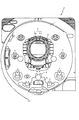
図1は、本実施例のパチンコ機Pの遊技盤の正面図である。遊技盤1の周囲には、球が入賞することにより5個から15個の球が払い出される複数の入賞口2が設けられている。また、遊技盤1の中央には、複数種類の識別情報としての図柄(特別図柄)などを表示する液晶ディスプレイ(以下単に「LCD」と略す)3が設けられている。このLCD3の表示画面は縦方向に3分割されており、3分割された各表示領域において、それぞれ上から下へ上下方向にスクロールしながら図柄の変動表示が行われる。
【0010】
LCD3の上方には、表面に「○」と「×」との普通図柄が表示された2つのLED6a,6bで構成された普通図柄表示装置6が配設されている。この普通図柄表示装置6では、遊技領域に打ち込まれた球がLCD3の両側に配設されたゲート7を通過した場合に、「○」と「×」とのLED6a,6bを交互に点灯させる変動表示が行われる。かかる変動表示が「○」のLED6aで終了した場合には、当たりとなって普通電動役物4が所定時間(例えば0.5秒)開放される。
【0011】
また、LCD3の下方には、図柄作動口(第1種始動口、普通電動役物)4が設けられており、球がこの図柄作動口4へ入賞することにより、前記したLCD3の変動表示が開始される。図柄作動口4の下方には、特定入賞口(大入賞口)5が設けられている。この特定入賞口5は、LCD3の変動後の表示結果が予め定められた図柄の組み合わせの1つと一致する場合に、大当たりとなって、球が入賞しやすいように所定時間(例えば、30秒経過するまで、或いは、球が10個入賞するまで)開放される入賞口である。
【0012】
この特定入賞口5内には、Vゾーン5aが設けられており、特定入賞口5の開放中に、球がVゾーン5a内を通過すると、継続権が成立して、特定入賞口5の閉鎖後、再度、その特定入賞口5が所定時間(又は、特定入賞口5に球が所定個数入賞するまで)開放される。この特定入賞口5の開閉動作は、最高で16回(16ラウンド)繰り返し可能にされており、開閉動作の行われ得る状態が、いわゆる所定の遊技価値が付与された状態(特別遊技状態)である。
【0013】
なお、第3種パチンコ遊技機において所定の遊技価値が付与された状態(特別遊技状態)とは、LCD3の変動後の表示結果が予め定められた図柄の組み合わせの1つと一致する場合に、特定入賞口が所定時間開放されることをいう。この特定入賞口の開放中に、球がその特定入賞口内へ入賞すると、特定入賞口とは別に設けられた大入賞口が所定時間、所定回数開放される。
【0014】
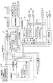
図2は、かかるパチンコ機Pの電気的構成を示したブロック図である。パチンコ機Pの主制御基板Cには、演算装置である1チップマイコンとしてのMPU11が搭載されている。このMPU11には、MPU11により実行される各種の制御プログラムや固定値データを記憶したROM12と、そのROM12内に記憶される制御プログラムの実行に当たって各種のデータ等を一時的に記憶するためのメモリであるRAM13と、割込回路やタイマ回路、データ送受信回路などの各種回路が内蔵されている。図4から図6に示すフローチャートのプログラムは、制御プログラムの一部としてROM12内に記憶されている。
【0015】
RAM13には、パチンコ機Pの電源のオフ後においても、後述する電源基板50からバックアップ電圧が供給されて、パチンコ機Pの電源のオフ後もデータを保持(バックアップ)できるように構成されている。このRAM13は、各種のデータ等を一時的に記憶するためのメモリやエリアの他に、バックアップエリア13aを備えている。バックアップエリア13aは、停電などの発生により電源が切断された場合、電源の再入時に、パチンコ機Pの状態を電源切断前の状態に復帰させるため、電源切断時(停電発生時を含む。以下、同様)のスタックポインタや、各レジスタ、I/O等の値を記憶しておくためのエリアである。バックアップエリア13aへの書き込みは、NMI割込処理(図4参照)によって電源切断時に実行され、逆にバックアップエリア13aに書き込まれた各値の復帰は、電源入時(停電解消による電源入を含む。以下、同様)の復電処理(図6参照)において実行される。
【0016】
なお、MPU11のNMI(Non Maskable Interrupt)端子(ノンマスカブル割込端子)には、停電等の発生による電源断時に、後述する停電監視回路50bから出力される停電信号51が合成回路10を介して入力されるように構成されており、停電の発生により、図4の停電時処理(NMI割込処理)が即座に実行される。合成回路10の詳細については図3を参照しつつ後述する。
【0017】
かかるROM12およびRAM13を内蔵したMPU11は、アドレスバス及びデータバスで構成されるバスライン14を介して入出力ポート15と接続されている。入出力ポート15は、電源基板50に設けられたクリアスイッチ50cと、払出用モータ26によって賞球や貸球の払出制御を行う払出制御基板Hと、前述した特別図柄及び普通図柄の変動表示の制御を行う表示用制御基板Dと、スピーカ42から効果音の出力制御を行うと共にLEDや各種ランプ43の点灯制御を行う音声ランプ制御基板Sと、そのほか他の入出力装置43とにそれぞれ接続されている。
【0018】
払出制御基板Hは、賞球や貸し球の払出制御を行うものであり、演算装置であるMPU21と、そのMPU21により実行される制御プログラムや固定値データ等を記憶したROM22と、ワークメモリ等として使用されるRAM23とを備えている。図4及び図7に示すフローチャートのプログラムは、制御プログラムの一部としてROM22内に記憶されている。
【0019】
払出制御基板HのRAM23には、前述した主制御基板CのRAM13と同様に、パチンコ機Pの電源のオフ後においても、後述する電源基板50からバックアップ電圧が供給されて、パチンコ機Pの電源のオフ後もデータを保持(バックアップ)できるように構成されている。このRAM23は、各種のデータ等を一時的に記憶するためのメモリやエリアの他に、バックアップエリア23aを備えている。
【0020】
バックアップエリア23aは、停電などの発生により電源が切断された場合、電源の再入時に、パチンコ機Pの状態を電源切断前の状態に復帰させるため、電源切断時(停電発生時を含む。以下、同様)のスタックポインタや、各レジスタ、I/O等の値を記憶しておくためのエリアである。このバックアップエリア23aへの書き込みは、NMI割込処理(図4参照)によって電源切断時に実行され、逆にバックアップエリア23aに書き込まれた各値の復帰は、電源入時(停電解消による電源入を含む。以下、同様)の復電処理において実行される。
【0021】
なお、MPU21のNMI(Non Maskable Interrupt)端子(ノンマスカブル割込端子)には、停電等の発生による電源断時に、後述する停電監視回路50bから出力される停電信号51が合成回路20を介して入力されるように構成されており、停電の発生により、図4の停電時処理(NMI割込処理)が即座に実行される。合成回路20の詳細については図3を参照しつつ後述する。
【0022】
かかるROM22およびRAM23を内蔵したMPU21は、アドレスバス及びデータバスで構成されるバスライン24を介して入出力ポート25と接続されている。入出力ポート25は、電源基板50に設けられたクリアスイッチ50cと、主制御基板Cと、賞球や貸し球を払い出すための払出用モータ26と、球を遊技領域へ発射するための発射制御基板Bと、そのほか他の入出力装置43とにそれぞれ接続されている。
【0023】
発射制御基板Bは、球を遊技領域へ発射するための発射用モータ28について駆動の許可と禁止とを制御するためのものである。発射用モータ28は、次の3条件が整っている場合に駆動が許可される(駆動が可能とされる)。即ち、第1に、払出制御基板Hから発射許可信号が出力されていること。第2に、ハンドル27に設けられたタッチセンサ29から遊技者がハンドル27をタッチしていることを示す信号が出力されていること。第3に、発射をストップさせるためのストップスイッチ30が操作されていないこと。以上の3条件が整っている場合に、発射制御基板Bは発射用モータ28へ駆動を許可する信号を出力する。かかる信号が出力されている状態でハンドルが操作されると、発射用モータ28は、ハンドルの操作量に応じた強度で駆動し、その強度で球を遊技領域へ発射する。
【0024】
表示用制御基板Dは、LCD3を用いた特別図柄の変動表示と、普通図柄表示装置6を用いた普通図柄の変動表示とを制御するためのものである。この表示用制御基板Dは、MPU31と、ROM32と、ワークRAM33と、ビデオRAM34と、キャラクタROM35と、画像コントローラ36と、入力ポート37と、2つの出力ポート39,40とを備えている。入力ポート37の入力には、主制御基板Cの出力が接続され、その入力ポート37の出力は、MPU31と、ROM32と、ワークRAM33と、画像コントローラ36と、一方の出力ポート39とを接続するバスライン38と接続されている。この一方の出力ポート39の出力には普通図柄表示装置6のLED6a,6bが接続されている。また、画像コントローラ36はバスライン38とは別の第2のバスライン41によって出力ポート40の入力に接続されており、その出力ポート40の出力にはLCD3が接続されている。
【0025】
表示用制御基板DのMPU31は、主制御基板Cから送信される表示命令に基づいてLCD3及び普通図柄表示装置6の表示を制御するためのものである。ROM32は、そのMPU31により実行される各種の制御プログラムや固定値データを記憶するためのメモリであり、ワークRAM33は、MPU31による各種プログラムの実行時に使用されるワークデータやフラグを一時的に記憶するためのメモリである。
【0026】
ビデオRAM34は、LCD3に表示される表示データを記憶するためのメモリであり、このビデオRAM34の内容を書き替えることにより、LCD3の表示内容が変更される。キャラクタROM35は、LCD3に表示される図柄などのキャラクタデータを記憶するためのメモリである。画像コントローラ36は、MPU31、ビデオRAM34、出力ポート40のそれぞれのタイミングを調整してデータの読み書きに介在すると共に、ビデオRAM34に記憶される表示データを、キャラクタROM35から所定のタイミングで読み出してLCD3に表示させるものである。
【0027】
電源基板50は、パチンコ機Pの各部に電力を供給するための電源部50aと、停電監視回路50bと、クリアスイッチ50cとを備えている。停電監視回路50bは、停電等の発生による電源断時に、主制御基板CのMPU11のNMI端子および払出制御基板HのMPU21のNMI端子へ、それぞれ合成回路10,20を介して、停電信号51を出力するための回路である。停電監視回路50bは、電源部50aから出力される最も大きい電圧である直流安定24ボルトの電圧を監視し、この電圧が22ボルト未満になった場合に停電(電源断)の発生と判断して、停電信号51を主制御基板C及び払出制御基板Hへ出力するように構成されている。この停電信号51の出力によって、主制御基板C及び払出制御基板Hは、停電の発生を認識し、停電時処理(図4のNMI割込処理)を実行する。
【0028】
なお、電源部50aは、直流安定24ボルトの電圧が22ボルト未満になった後においても、かかる停電時処理の実行に充分な時間の間、制御系の駆動電圧である5ボルトの出力を正常値に維持するように構成されている。よって、主制御基板C及び払出制御基板Hは、停電時処理を正常に実行し完了することができるのである。
【0029】
クリアスイッチ50cは、主制御基板CのRAM13および払出制御基板HのRAM23にバックアップされるデータをクリアするためのスイッチであり、押しボタンタイプのスイッチで構成されている。クリアスイッチ50cが押下されると、クリア信号52が主制御基板Cおよび払出制御基板Hへ出力される。このクリアスイッチ50cが押下された状態でパチンコ機Pの電源が投入されると(停電解消による電源入を含む)、主制御基板Cおよび払出制御基板Hによって、それぞれのRAM13,23のデータがクリアされる。
【0030】
図3を参照して、主制御基板Cおよび払出制御基板Hに設けられる合成回路10,20について説明する。図3は合成回路10,20を説明するために、その合成回路10,20に関連する部分の構成を示した図である。合成回路10,20は、電源基板50の停電監視回路50bから出力される停電信号51を、相手方の制御基板C,Hへ出力すると共に、その停電信号51と相手方の制御基板C,Hから出力される停電を示す信号とを合成して(本実施例ではナンド論理をとって)、MPU11,21のNMI端子へ出力する回路である。この合成回路10,20を介して停電信号51をMPU11,21へ入力することにより、ノイズ等の影響による不正規な停電信号のMPU11,21への入力を抑制して、図4の停電時処理を停電等の発生による電源断時に適正に実行することができる。
【0031】
合成回路10,20は、主制御基板Cおよび払出制御基板Hにそれぞれ設けられており、いずれも2入力のナンド回路10a,20aと、第1コネクタ10b,20bと、第2コネクタ10c,20cと、入出力の方向性を一方向に限定するバッファ10d,20dとを備えて構成されている。電源基板50の停電監視回路50bの出力は、即ち停電信号51の出力ラインは、主基板用コネクタ51a1および主基板用信号線51a2を介して主制御基板Cの第1コネクタ10bと接続されると共に、払出基板用コネクタ51b1および払出基板用信号線51b2を介して払出制御基板Hの第1コネクタ20bと接続されている。なお、主基板用信号線51a2と払出基板用信号線51b2とは、2本の別個(別体)の信号線で構成されている。
【0032】
主制御基板Cの第1コネクタ10bは、2入力ナンド回路10aの一方の入力端に接続されると共に、バッファ10d、第2コネクタ10cおよび信号線10eを介して払出制御基板Hへ出力され、更に払出制御基板Hの第2コネクタ20cを介して2入力ナンド回路20aの他方の入力端に接続されている。また、払出制御基板Hの第1コネクタ20bは、2入力ナンド回路20aの一方の入力端に接続されると共に、バッファ20d、第2コネクタ20cおよび信号線20eを介して主制御基板Cへ出力され、更に主制御基板Cの第2コネクタ10cを介して2入力ナンド回路10aの他方の入力端に接続されている。主制御基板Cの2入力ナンド回路10aの出力端はMPU11のNMI端子に、払出制御基板Hの2入力ナンド回路20aの出力端はMPU21のNMI端子に、それぞれ接続されている。両MPU11,21は、このNMI端子へ入力される信号が立ち下がるタイミングで、図4のNMI割込処理(停電時処理)を実行する。
【0033】
次に、上記のように構成された合成回路10,20の動作を説明する。停電等が発生して電源断となると、停電監視回路50bから停電信号51が出力される。停電信号51は、主基板用コネクタ51a1および主基板用信号線51a2を通って、主制御基板Cの第1コネクタ10bへ入力される。主制御基板Cの第1コネクタ10bへ入力された停電信号51は、ナンド回路10aの一方の入力端に入力されると共に、バッファ10d、第2コネクタ10cおよび信号線10eを通って、払出制御基板Hの第2コネクタ20cへ入力され、更に払出制御基板Hのナンド回路20aの他方の入力端に入力される。
【0034】
同様に、停電監視回路50bから出力された停電信号51は、払出基板用コネクタ51b1および払出基板用信号線51b2を通って、払出制御基板Hの第1コネクタ20bへ入力される。払出制御基板Hの第1コネクタ20bへ入力された停電信号51は、ナンド回路20aの一方の入力端に入力されると共に、バッファ20d、第2コネクタ20cおよび信号線20eを通って、主制御基板Cの第2コネクタ10cへ入力され、更に主制御基板Cのナンド回路10aの他方の入力端に入力される。
【0035】
主制御基板Cおよび払出制御基板Hのナンド回路10a,20aは、両方入力端に停電信号51(および停電を示す信号)が入力されると、その出力をハイからロウへ立ち下げる。その結果、MPU11,21のNMI端子への入力信号が立ち下がり、その立ち下がりのタイミングで図4のNMI割込処理(停電時処理)がそれぞれ実行される。
【0036】
このように、合成回路10,20を介して停電信号51をMPU11,21へ入力することにより、ノイズ等の影響による不正規な停電信号のMPU11,21への入力を抑制して、停電時処理を停電等の発生による電源断時に適正に実行することができる。即ち、合成回路10,20は、停電監視回路50bから出力される停電信号51と、相手方の制御基板C,Hから出力される停電を示す信号とを合成して、両信号が出力されている場合に限り、MPU11,21へ停電信号51を出力するので、例えば、一方の信号線51a1,51b1にのみノイズがのり、その結果、不正規な停電信号が出力されても、合成回路10,20からMPU11,21へ停電信号51が出力されることはないからである。特に、4本の信号線51a1,51b1,10e,20eは、それぞれ別個(別体)の信号線で構成されており、且つ、電源基板50、主制御基板Cおよび払出制御基板Hの配置関係により、4本の信号線51a1,51b1,10e,20eは異なる位置に配線されるので、これら4本の信号線51a1,51b1,10e,20eに同時にノイズがのることは極めて希である。よって、ノイズ等の影響による不正規な停電信号による停電時処理の実行を非常に高いレベルで防止することができる。
【0037】
第1コネクタ10b,20bと第2コネクタ10c,20cとは、別個(別体)のコネクタで構成されているので、不正行為によって一方のコネクタが抜き取られることがあっても、不正な停電信号をMPU11,21へ出力することはできない。即ち、主制御基板Cの第1コネクタ10bが抜き取られ、別の不正なコネクタが接続されて、その不正なコネクタから不正な停電信号が出力されても、払出制御基板Hの第1コネクタ20bへ停電信号51が入力されない限り、主制御基板Cのナンド回路10aはMPU11へ停電信号51を出力しない。また、主制御基板Cの第2コネクタ10cが抜き取られ、別の不正なコネクタが接続されて、その不正なコネクタから不正な停電信号が出力されても、バッファ10dによってナンド回路10aの一方の入力端への信号入力が阻止されるので、主制御基板Cの第1コネクタ10bへ停電信号51が入力されない限り、主制御基板Cのナンド回路10aはMPU11へ停電信号51を出力しない。払出制御基板Hの場合も同様である。
【0038】
このように本実施例の合成回路10,20によれば、第1コネクタ10b,20bと第2コネクタ10c,20cとは、別個(別体)のコネクタで構成されており、バッファ10d,20dが設けられているので、不正行為によって一方のコネクタが抜き取られることがあっても、不正な停電信号をMPU11,21へ出力することはできない。よって、不正に停電信号を主制御基板Cへ出力し、その主制御基板Cをリセットさせて、不当に大当たりを誘発する等といった不正行為を防止することができる。
【0039】
なお、合成回路10,20のナンド回路10a,20aをアンド回路や他の回路に変更したり、バッファ10d,20dをインバータや他の回路に変更することは、上述した機能を維持する範囲において当然に可能である。
【0040】
次に、上記のように構成されたパチンコ機Pで実行される各処理を、図4から図7の各フローチャートを参照して説明する。図4は、停電の発生等によるパチンコ機Pの電源断時に、主制御基板C及び払出制御基板Hで実行されるNMI割込処理のフローチャートである。このNMI割込処理により、停電の発生等による電源断時の主制御基板C及び払出制御基板Hの状態が、それぞれのバックアップエリア13a,23aに記憶される。
【0041】
停電の発生等によりパチンコ機Pの電源が断されると、停電監視回路50bから停電信号51が主制御基板C及び払出制御基板Hの各MPU11,21のNMI(Non Maskable Interrupt)端子へ各合成回路10,20を介して、それぞれ出力される。すると、MPU11,21は、実行中の制御を中断して、図4のNMI割込処理を開始する。図4のNMI割込処理は、主制御基板C及び払出制御基板Hの各ROM12,22内にそれぞれ記憶されている。停電信号51が出力された後所定時間は、主制御基板C及び払出制御基板Hの処理が実行可能なように電源部50aから電力供給がなされており、この所定時間内にNMI割込処理が実行される。
【0042】
NMI割込処理(停電時処理)では、まず、各レジスタおよびI/O等の値をスタックエリアへ書き込み(S1)、次に、スタックポインタの値をバックアップエリア13a,23aへ書き込んで退避する(S2)。更に、停電発生情報をバックアップエリア13a,23aへ書き込んで(S3)、停電の発生等による電源断時の状態を記憶する。その後、その他停電処理を実行した後(S4)、電源が完全に断して処理が実行できなくなるまで、処理をループする。
【0043】
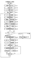
図5は、パチンコ機Pの主制御基板Cにおいて実行されるメイン処理のフローチャートである。パチンコ機Pの主な制御は、このメイン処理によって実行される。メイン処理では、まず、割込を禁止した後(S11)、図6に示す初期化処理を実行する(S12)。
【0044】
図6は、パチンコ機Pの電源入時に主制御基板Cのメイン処理の中で実行される初期化処理(S12)のフローチャートである。この処理では、バックアップが有効であれば、バックアップエリア13aに記憶された各データを元の状態に戻し、遊技の制御を電源が断される前の状態から続行する。一方、バックアップが有効でなかったり、或いは、バックアップが有効であっても電源入時にクリアスイッチ50cが押下された場合には、RAMクリア及び初期化処理を実行する。なお、この初期化処理(S12)は、サブルーチンの形式で記載されているが、スタックポインタの設定前に実行される処理なので、実際には、サブルーチンコールされずに、S11の処理後に順に実行される。
【0045】
まず、スタックポインタを設定し(S41)、次に、クリアスイッチ50cがオンされているか否かを確認する(S42)。クリアスイッチ50cがオンされていなければ(S42:No)、バックアップが有効であるか否かを確認する(S43)。この確認は、RAM13の所定のエリアに書き込まれたキーワードが正しく記憶されているか否かにより判断する。キーワードが正しく記憶されていればバックアップは有効であり、逆に、キーワードが正しくなければバックアップデータは破壊されているので、そのバックアップは有効ではない。バックアップが有効であれば(S43:Yes)、処理をS47へ移行して、主制御基板Cの各状態を電源断前の状態に復帰させる。一方、バックアップが有効でなかったり(S43:No)、或いはクリアスイッチ50cがオンされていれば(S42:Yes)、RAMクリア及び初期化処理を実行して(S44)、RAM13及びI/O等の各値を初期化し、この初期化処理を終了する。S44の処理の終了後は、図5のS13の処理が実行される。
【0046】
S47からの処理では、まず、バックアップエリア13aからスタックポインタの値を読み出して、これをスタックポインタへ書き込み、電源断前(停電前)の状態、即ちNMI割込発生前の状態に戻す(S47)。スタックポインタの値を戻した後のスタックエリア、即ちバックアップエリア13aへ退避した各レジスタやI/O等のデータをそのバックアップエリア13aから読み出して、これら各データを元のレジスタやI/O等へ書き込む(S48)。更に、割込状態を停電発生時に実行される図4の処理で記憶しておいた電源断前(停電前)の状態、即ちNMI割込発生前の状態に戻し(S49)、NMI割込リターンを実行して、処理を電源断前に実行していたところへ戻して、制御を電源断前の状態から続行する。
【0047】
図5のフローチャートの戻って説明する。S13の処理ではタイマ割込の設定を行う(S13)。ここで設定されるタイマ割込としては、各制御基板H,D,Sへコマンドを送信するためのストローブ信号を発生させるタイマ割込などがある。タイマ割込の設定後は、各割込を許可状態とする(S14)。割込の許可後は、特別図柄変動処理(S25)や、表示データ作成処理(S27)、ランプ・情報処理(S28)などにより、前回の処理で更新された出力データを一度に各ポートへ出力するポート出力処理を実行する(S15)。
【0048】
更に、大当たりを決定するための乱数カウンタの値などを「+1」更新する乱数更新処理(S16)を実行し、記憶タイマ減算処理を実行する(S17)。記憶タイマ減算処理は、大当たり判定の保留球が所定数以上あり、且つ、LCD3において図柄の変動表示中である場合に、図柄の変動表示の時間短縮を行うものである。
【0049】
スイッチ監視処理(S18)は、インターバル割込で読み込まれた各スイッチの状態に応じて、遊技領域へ打ち込まれた球の入賞口2や大入賞口5、図柄作動口4への入賞、球のゲート7の通過、更には賞球の払い出し等に関する処理を行うものである。図柄カウンタ更新処理(S20)では、LCD3で行われる変動表示の結果、停止表示される図柄を決定するためのカウンタの更新処理が行われる。また、図柄チェック処理(S21)では、図柄カウンタ更新処理(S20)で更新されたカウンタの値に基づいて、特別図柄変動処理(S25)で使用される大当たり図柄や、はずれ図柄、更にはリーチ図柄などが決定される。
【0050】
その後、普通図柄変動処理(S23)によって、普通図柄としての「○」及び「×」のLED6a,6bの変動表示を行うと共に、その変動表示の結果、大当たりが発生した場合には普通電動役物(第1種図柄作動口4)を所定時間開放する大当たり処理を実行する。その後、状態フラグをチェックし(S24)、LCD3において特別図柄の変動開始または変動表示中であれば(S24:図柄変動中)、特別図柄変動処理(S25)によって、球が図柄作動口4を通過するタイミングで読み取った乱数カウンタの値に基づいて、大当たりか否かの判定が行われると共に、LCD3にて特別図柄の変動処理を実行する。一方、状態フラグをチェックした結果、大当たり中であれば(S24:大当り中)、大入賞口5を開放するなどの大当たり処理(S26)を実行する。更に、状態フラグをチェックした結果、図柄の変動中でも大当たり中でもなければ(S24:その他)、S25及びS26の処理をスキップして、S27の表示データ作成処理へ移行する。
【0051】
表示データ作成処理(S27)では、図柄の変動表示以外にLCD3に表示されるデモデータや、「○」及び「×」のLED6a,6bの表示データなどが作成され、ランプ・情報処理(S28)では、保留球のランプデータをはじめ、各種のランプデータが作成される。効果音処理(S29)では、遊技の状況に応じた効果音データが作成される。なお、これらの表示データ及び効果音データは、前記したポート出力処理(S15)やタイマ割込処理によって各制御基板H,D,Sへ出力される。
【0052】
効果音処理(S29)の終了後は、次のS15の処理の実行タイミングが到来するまでの残余時間の間、大当たりを決定するための乱数カウンタの初期値を更新する乱数初期値更新処理(S30)を繰り返し実行する。S15〜S29の各処理は定期的に実行する必要があるので、S31の処理において、前回のS15の処理の実行からの経過時間をチェックする(S31)。チェックの結果、前回のS15の処理の実行から所定時間経過していれば(S31:Yes)、処理をS15へ移行し、一方、所定時間経過していなければ(S31:No)、処理をS30へ移行して、乱数初期値更新処理(S30)の実行を繰り返す。ここで、S15〜S29の各処理の実行時間は、遊技の状態に応じて変化するので、次のS15の処理の実行タイミングが到来するまでの残余時間は、一定の時間ではない。よって、かかる残余時間を使用して乱数初期値更新処理(S30)を繰り返し実行することにより、乱数カウンタの初期値をランダムに更新することができる。
【0053】
図7は、払出制御基板Hのメイン処理のフローチャートである。このメイン処理では、まず、スタックポインタを設定し(S61)、次に、発射制御基板Bへ出力される発射許可信号をオフして(S62)、球の発射を禁止する。クリアスイッチ50cがオンされているか否かを確認し(S63)、オンされていなければ(S63:No)、バックアップが有効であるか否かを確認する(S64)。この確認は、RAM23の所定のエリアに書き込まれたキーワードが正しく記憶されているか否かにより判断する。キーワードが正しく記憶されていればバックアップは有効であり、逆に、キーワードが正しくなければバックアップデータは破壊されているので、そのバックアップは有効ではない。バックアップが有効であれば(S64:Yes)、処理をS72へ移行する。
【0054】
一方、バックアップが有効でなかったり(S64:No)、或いはクリアスイッチ50cがオンされていれば(S63:Yes)、RAMクリア及び初期化処理を実行して(S65)、RAM23及びI/O等の各値を初期化し、発射制御基板Bへ発射許可信号を出力した後(S67)、割込を許可して(S68)、払出制御基板Hの立ち上げ処理を終了する。その後は、払出制御基板Hのメイン処理で実行される各処理を実行し(S69)、この各処理を繰り返す。
【0055】
S72からの処理では、バックアップエリア23aからスタックポインタの値を読み出して、これをスタックポインタへ書き込み、電源断前(停電前)の状態、即ちNMI割込発生前の状態に戻す(S72)。その後、スタックポインタの値を戻した後のスタックエリア、即ちバックアップエリア23aへ退避した各レジスタやI/O等のデータをそのバックアップエリア23aから読み出して、これら各データを元のレジスタやI/O等へ書き込む(S73)。発射制御基板Bへ出力される発射許可信号も、この処理で停電前の状態に戻される。更に、割込状態を停電発生時に実行される図4の処理で記憶しておいた電源断前(停電前)の状態、即ちNMI割込発生前の状態に戻し(S74)、NMI割込リターンを実行して、処理を電源断前に実行していたところへ戻して、制御を電源断前の状態から続行する。
【0056】
以上説明したように、本実施例のパチンコ機Pによれば、合成回路10,20を介して停電信号51をMPU11,21へ入力することにより、ノイズ等の影響による不正規な停電信号のMPU11,21への入力を抑制して、停電時処理を停電等の発生による電源断時に適正に実行することができる。
【0057】
次に、図8から図13を参照して、第2実施例を説明する。前述した第1実施例は、ハード的な合成回路10,20を使用して、ノイズ等の影響による不正規な停電信号のMPU11,21への入力を抑制し、停電時処理を停電等の発生による電源断時に適正に実行するようにしたものである。これに対し、第2実施例は、ハード的な回路に代えてソフト制御を用いることで、ノイズ等の影響による不正規な停電信号による停電時処理の実行を抑制するものである。以下、前記した第1実施例と同一の部分には同一の符号を付してその説明を省略し、異なる部分についてのみ説明する。
【0058】
図8は、電源基板50の停電監視回路50bから出力される停電信号51の出力経路の説明図である。図8に示すように、第2実施例のパチンコ機Pでは、停電信号51は、主制御基板Cおよび払出制御基板Hの入出力ポート15,25を介して、それぞれのMPU11,21へ入力される(第2実施例では、停電信号51はMPU11,21のNMI端子に入力されない)。主制御基板CのMPU11は停電信号51を入力すると、入出力ポート15,25を介して、停電を示す信号を払出制御基板Hへ出力する。同様に、払出制御基板HのMPU21は停電信号51を入力すると、入出力ポート25,15を介して、停電を示す信号を主制御基板Cへ出力する。主制御基板Cおよび払出制御基板Hは、停電信号51と相手側の制御基板C,Hから出力される停電を示す信号とを入力した場合に、それぞれ停電時処理を実行する(図10及び図13参照)。
【0059】
次に、上記のように構成された第2実施例のパチンコ機Pで実行される各処理を、図9から図13の各フローチャートを参照して説明する。なお、図9から図11のフローチャートに示す処理は主制御基板Cで実行され、図12及び図13のフローチャートに示す処理は払出制御基板Hで実行される。
【0060】
図9は、パチンコ機Pの主制御基板Cにおいて実行される第2実施例のメイン処理のフローチャートである。第2実施例では、効果音処理(S29)の終了後は、次のS15の処理の実行タイミングが到来するまでの残余時間の間、大当たりを決定するための乱数カウンタの初期値を更新する乱数初期値更新処理(S30)と、図10に示す停電信号チェック処理(S32)とを繰り返し実行する。
【0061】
図10は、主制御基板Cで実行される停電信号チェック処理のフローチャートである。この停電信号チェック処理では、停電監視回路50bから停電信号51を入力した場合に、払出制御基板Hへ停電を示す信号を出力すると共に、払出制御基板Hから停電を示す信号を入力していれば停電時処理(S1〜S4)を実行する。
【0062】
まず、停電監視回路50bから停電信号51を入力しているか否かを確認し(S81)、入力していなければ(S81:No)、払出制御基板Hへ出力する停電を示す信号をオフして(S82)、この停電信号チェック処理を終了する。一方、停電信号51を入力していれば(S81:Yes)、払出制御基板Hへ停電を示す信号を出力し(S83)、払出制御基板Hから停電を示す信号を入力しているか否かを確認する(S84)。確認の結果、払出制御基板Hから停電を示す信号を入力していなければ(S84:No)、ノイズ等の原因で停電信号51が誤って入力されたものと判断できるので、停電時処理(S1〜S4)を実行することなく、この停電信号チェック処理を終了する。
【0063】
停電信号51を入力し(S81:Yes)且つ払出制御基板Hから停電を示す信号を入力していれば(S84:Yes)、確実に停電が発生した(電源が断された)ものと判断して、停電時処理を実行する。まず、停電時処理中に他の制御が実行されないように割込を禁止する(S85)。次に、スタックポインタの値を2減算して、この停電信号チェック処理(S32)の実行時(サブルーチンコール時)にスタックされた2バイトの戻り先アドレス(番地)をクリアする(S86)。これにより、停電時処理の実行に際して使用されるスタックエリアを戻り先番地分(本実施例では2バイト分)小さくできると共に、後述する復電処理の終了後における復帰の方式を、スタックメモリを使用したリターンではなく、所定番地へのジャンプで対応することができる。
【0064】
スタックポインタの値の減算後は、S1からS4の停電時処理を実行する。かかる停電時処理は、第1実施例の停電時処理(図4参照)と同様の処理であるので、その説明は省略する。なお、この停電時処理で記憶される割込状態は、S85の処理によって割込が禁止される前の割込状態である。
【0065】
図11は、パチンコ機Pの電源入時に主制御基板Cのメイン処理の中で実行される第2実施例の初期化処理(S12)のフローチャートである。初期化処理が第1実施例と第2実施例とで異なる点は、復電処理の終了後(S49の処理後)における復帰の方式である。第1実施例の初期化処理では、NMI割込リターンによって、停電発生時に(停電時処理の実行直前に)正に実行していたアドレスへ復帰したが(図6参照)、第2実施例の初期化処理では、図9に示すメイン処理のS15の処理へジャンプすることにより(S50)、通常の処理へ復帰する。これは第2実施例の停電時処理では、スタックメモリの有効使用のために、停電時処理の実行前に戻り先番地を記憶するスタックメモリをクリアしているからである(図10のS86参照)。
【0066】
なお、かかる戻り先番地を記憶するスタックメモリのクリアをしない場合(S86の処理を実行しない場合)には、第2実施例の初期化処理は、S49の処理の後にリターン命令を実行して終了する。また、S50の処理において、S15の処理へジャンプして通常の処理へ復帰することに代えて、図9のS31(またはS30)の処理へジャンプして通常の処理へ復帰するようにしても良い。
【0067】
図12は、払出制御基板Hの第2実施例のメイン処理のフローチャートである。第2実施例のメイン処理が第1実施例のメイン処理と異なる点は2点ある。第1点は、各処理(S69)と共に図13に示す停電信号チェック処理(S70)を繰り返し実行する点であり、第2点は、復電処理の終了後(S74の処理後)における復帰の方式である。第1実施例ではNMI割込リターンによって、停電発生時に(停電時処理の実行直前に)正に実行していたアドレスへ復帰したが(図7参照)、第2実施例ではS69の処理へジャンプすることにより、通常の処理へ復帰している。これは、主制御基板Cでの処理の場合と同様に、第2実施例の停電時処理(図13のS1〜S4)では、スタックメモリの有効使用のために、停電時処理の実行前に戻り先番地を記憶するスタックメモリをクリアしているからである(図13のS96参照)。
【0068】
図13は、払出制御基板Hで実行される停電信号チェック処理のフローチャートである。この停電信号チェック処理では、停電監視回路50bから停電信号51を入力した場合に、主制御基板Cへ停電を示す信号を出力すると共に、主制御基板Cから停電を示す信号を入力していれば停電時処理(S1〜S4)を実行する。
【0069】
まず、停電監視回路50bから停電信号51を入力しているか否かを確認し(S91)、入力していなければ(S91:No)、主制御基板Cへ出力する停電を示す信号をオフして(S92)、この停電信号チェック処理を終了する。一方、停電信号51を入力していれば(S91:Yes)、主制御基板Cへ停電を示す信号を出力し(S93)、主制御基板Cから停電を示す信号を入力しているか否かを確認する(S94)。確認の結果、主制御基板Cから停電を示す信号を入力していなければ(S94:No)、ノイズ等の原因で停電信号51が誤って入力されたものと判断できるので、停電時処理(S1〜S4)を実行することなく、この停電信号チェック処理を終了する。
【0070】
停電信号51を入力し(S91:Yes)且つ主制御基板Cから停電を示す信号を入力していれば(S94:Yes)、確実に停電が発生した(電源が断された)ものと判断して、停電時処理を実行する。まず、停電時処理中に他の制御が実行されないように割込を禁止する(S95)。次に、スタックポインタの値を2減算して、この停電信号チェック処理(S70)の実行時(サブルーチンコール時)にスタックされた2バイトの戻り先アドレス(番地)をクリアする(S96)。これにより、停電時処理の実行に際して使用されるスタックエリアを戻り先番地分(本実施例では2バイト分)小さくできると共に、図12で説明したように、復電処理の終了後における復帰の方式を、スタックメモリを使用したリターンではなく、所定番地へのジャンプで対応することができる。
【0071】
スタックポインタの値の減算後は、S1からS4の停電時処理を実行する。かかる停電時処理は、第1実施例の停電時処理(図4参照)と同様の処理であるので、その説明は省略する。なお、この停電時処理で記憶される割込状態は、S95の処理によって割込が禁止される前の割込状態である。
【0072】
以上説明したように、第2実施例のパチンコ機Pによれば、停電信号51が主制御基板Cおよび払出制御基板HのMPU11,21へそれぞれ入力されると、主制御基板CのMPU11は払出制御基板Hへ停電を示す信号を出力し、払出制御基板HのMPU21は主制御基板Cへ停電を示す信号を出力する。主制御基板Cおよび払出制御基板Hは、停電信号51と相手側の制御基板C,Hから出力される停電を示す信号とを同時に入力した場合に、それぞれの停電時処理を実行するように構成されているので、ノイズ等の影響を排除して、停電時処理を停電等の発生による電源断時に適正に実行することができる。
【0073】
なお、上記第1及び第2実施例における請求項1記載の第1退避手段及び第2退避手段、並びに請求項6記載の退避手段としては、S1からS4の各処理(図4,図10,図13)が該当し、第2実施例の第1停電信号出力手段としてはS83の処理が、第2実施例の第2停電信号出力手段としてはS93の処理が、それぞれ該当する。また、請求項2記載の第1復電手段としてはS47〜S49の各処理(図6,図11)が該当し、第2復電手段としてはS72〜S74の各処理(図7,図12)が該当する。
【0074】
以上、実施例に基づき本発明を説明したが、本発明は上記実施例に何ら限定されるものではなく、本発明の趣旨を逸脱しない範囲内で種々の改良変形が可能であることは容易に推察できるものである。
【0075】
上記各実施例では、停電信号51を例に説明したが、本発明は必ずしも停電信号51に限定されるものではなく、停電信号51と同様に、2以上の制御基板へ出力される信号、例えば電源基板50から主制御基板Cおよび払出制御基板Hへ出力されるクリア信号52などに適用しても良い。
【0076】
また、1の制御基板へのみ出力すれば足りる信号であっても、その信号を1の制御基板のみならず他の制御基板へ出力し、その他の制御基板へ出力された信号を、他の制御基板から1の制御基板へ転送(出力)するように構成する。1の制御基板に合成回路を設け、その合成回路によって、1の制御基板へ直接出力された信号と、他の制御基板を介して1の制御基板へ転送(出力)された信号とを合成し、両信号が出力されている場合に限り、その信号に応じた動作を1の制御基板に実行させるように構成しても良い。かかる構成によれば、ノイズや不正行為等を原因とする不正規な信号による1の制御基板の誤動作を極力抑制することができる。なお、信号の合成回路は必ずしも1の制御基板内に設ける必要は無く、その合成回路を1の制御基板と別個に設けるようにしても良い。
【0077】
更に、第1実施例では、停電信号51は、MPU11,21のNMI端子へ出力されて、NMI割込処理によって停電時処理(S1〜S4)が実行されるように構成された。しかし、かかる構成に代えて、停電信号51を、MPU11,21のINT端子へ出力して、INT割込処理によって停電時処理(S1〜S4)を実行するように構成しても良い。
【0078】
第1実施例において、合成回路10,20は、主制御基板C内または払出制御基板H内に設けられた。しかし、必ずしも、合成回路10,20を主制御基板C内または払出制御基板H内に設ける必要はなく、例えば、合成回路を主制御基板Cおよび払出制御基板Hとは別個の基板として構成し、リード線などによって、主制御基板C又は払出制御基板Hと接続するようにしても良い。合成回路を合成回路基板として、主制御基板Cおよび払出制御基板Hと別個に構成すれば、主制御基板C用の合成回路と払出制御基板H用の合成回路とを共通化することができ、その分、設計コストや製造コストを低減することができる。
【0079】
本発明を上記実施例とは異なるタイプのパチンコ機等に実施しても良い。例えば、一度大当たりすると、それを含めて複数回(例えば2回、3回)大当たり状態が発生するまで、大当たり期待値が高められるようなパチンコ機(通称、2回権利物、3回権利物と称される)として実施しても良い。また、大当たり図柄が表示された後に、所定の領域に球を入賞させることを必要条件として特別遊技状態となるパチンコ機として実施しても良い。更に、パチンコ機以外にも、アレパチ、雀球、スロットマシン、いわゆるパチンコ機とスロットマシンとが融合した遊技機などの各種遊技機として実施するようにしても良い。
【0080】
なお、スロットマシンは、例えばコインを投入して図柄有効ラインを決定させた状態で操作レバーを操作することにより図柄が変動され、ストップボタンを操作することにより図柄が停止されて確定される周知のものである。従って、スロットマシンの基本概念としては、「複数の図柄からなる図柄列を変動表示した後に図柄を確定表示する可変表示手段を備え、始動用操作手段(例えば操作レバー)の操作に起因して図柄の変動が開始され、停止用操作手段(例えばストップボタン)の操作に起因して、或いは、所定時間経過することにより、図柄の変動が停止され、その停止時の確定図柄が特定図柄であることを必要条件として、遊技者に有利な特別遊技状態を発生させる特別遊技状態発生手段とを備えたスロットマシン」となり、この場合、遊技媒体はコイン、メダル等が代表例として挙げられる。
【0081】
また、パチンコ機とスロットマシンとが融合した遊技機の具体例としては、複数の図柄からなる図柄列を変動表示した後に図柄を確定表示する可変表示手段を備えており、球打出用のハンドルを備えていないものが挙げられる。この場合、所定の操作(ボタン操作)に基づく所定量の球の投入の後、例えば操作レバーの操作に起因して図柄の変動が開始され、例えばストップボタンの操作に起因して、或いは、所定時間経過することにより、図柄の変動が停止され、その停止時の確定図柄がいわゆる大当たり図柄であることを必要条件として遊技者に有利な大当たり状態が発生させられ、遊技者には、下部の受皿に多量の球が払い出されるものである。
【0082】
以下に本発明の変形例を示す。請求項1記載の遊技機において、停電が解消すると前記第1退避手段によって前記第1バックアップ手段へ退避されたデータを復帰して遊技を再開する第1復電手段と、停電が解消すると前記第2退避手段によって前記第2バックアップ手段へ退避されたデータを復帰して遊技を再開する第2復電手段とを備えていることを特徴とする遊技機1。停電が解消すると、第1復電手段によって、第1退避手段により第1バックアップ手段へ退避されたデータが復帰され、第2復電手段によって、第2退避手段により第2バックアップ手段へ退避されたデータが復帰されるので、停電の解消により遊技を再開することができる。
【0083】
請求項1記載の遊技機または遊技機1において、前記第1退避手段は、前記停電監視手段から出力された停電信号と前記第2停電信号出力手段から出力された停電を示す信号とを同時に受信した場合に動作するものであり、前記第2退避手段は、前記停電監視手段から出力された停電信号と前記第1停電信号出力手段から出力された停電を示す信号とを同時に受信した場合に動作するものであることを特徴とする遊技機2。第1退避手段または第2退避手段は、停電監視手段から出力された停電信号と第2停電信号出力手段または第1停電信号出力手段から出力された停電を示す信号とを同時に受信した場合に動作するように構成されているので、例えば、ノイズや不正行為等を原因として停電信号や停電を示す信号が個別に入力されたとしても、第1退避手段または第2退避手段は動作しない。また、停電信号が第1制御手段または第2制御手段の一方にのみ入力された場合にも、第1退避手段または第2退避手段は動作しない。よって、第1退避手段または第2退避手段の誤動作を抑制して、遊技機を正確に動作させることができる。
【0084】
請求項1記載の遊技機または遊技機1若しくは2において、前記停電監視手段は、1の信号線によって前記第1制御手段と接続されると共に、その1の信号線とは異なる他の信号線によって前記第2制御手段と接続されるものであり、前記第1停電信号出力手段は、更に別の信号線によって前記第2制御手段と接続され、前記第2停電信号出力手段は、更に別の信号線によって前記第1制御手段と接続されていることを特徴とする遊技機3。遊技機3によれば、第1退避手段および第2退避手段は、1の信号線と他の信号線と更に別の信号線とによって停電信号または停電を示す信号を入力した場合に動作するので、ノイズ等がいずれか1本の信号線にのったとしても動作することはない。よって、ノイズなどの影響による誤動作を抑制して、遊技機を正確に動作させることができる。
【0085】
遊技機3において、前記停電監視手段と前記第1制御手段とを接続する1の信号線から出力される停電信号と、前記第2停電信号出力手段と前記第1制御手段とを接続する別の信号線から出力される停電を示す信号とを合成する第1合成手段と、前記停電監視手段と前記第2制御手段とを接続する他の信号線から出力される停電信号と、前記第1停電信号出力手段と前記第2制御手段とを接続する別の信号線から出力される停電を示す信号とを合成する第2合成手段とを備え、前記第1退避手段は前記第1合成手段の出力に基づいて動作するものであり、前記第2退避手段は前記第2合成手段の出力に基づいて動作するものであることを特徴とする遊技機4。第1合成手段または第2合成手段としては、例えばアンド回路やナンド回路などが例示される。なお、第1合成手段を第1制御手段と別体にして構成しても良いし、第2合成手段を第2制御手段と別体にして構成しても良い。
【0086】
遊技機4において、前記第1合成手段は、前記第1制御手段に設けられると共に、前記第2合成手段は、前記第2制御手段に設けられていることを特徴とする遊技機5。第1合成手段を第1制御手段に設けることにより、第1制御手段内で停電信号と第2停電信号出力手段から出力される停電を示す信号とを合成することができ、第2合成手段を第2制御手段に設けることにより、第2制御手段内で停電信号と第1停電信号出力手段から出力される停電を示す信号とを合成することができるので、ノイズや不正行為等を原因とする不正規な停電信号の除去効果を一層向上することができる。
【0087】
遊技機3から5のいずれかにおいて、前記停電監視手段と前記第1制御手段とを接続する1の信号線と、前記第2停電信号出力手段と前記第1制御手段とを接続する別の信号線とは、前記第1制御手段に別個のコネクタを介して接続されており、前記停電監視手段と前記第2制御手段とを接続する他の信号線と、前記第1停電信号出力手段と前記第2制御手段とを接続する別の信号線とは、前記第2制御手段に別個のコネクタを介して接続されていることを特徴とする遊技機6。
【0088】
遊技機3から6のいずれかにおいて、前記停電監視手段と前記第1制御手段とを接続する1の信号線は、前記第1停電信号出力手段と前記第2制御手段とを接続する別の信号線と接続され、前記停電監視手段と前記第2制御手段とを接続する他の信号線は、前記第2停電信号出力手段と前記第1制御手段とを接続する別の信号線と接続されていることを特徴とする遊技機7。よって、第1制御手段へ入力された停電信号を、停電を示す信号として第2制御手段へ転送することができる。同様に、第2制御手段へ入力された停電信号を、停電を示す信号として第1制御手段へ転送することができる。
【0089】
遊技機7において、前記第1停電信号出力手段と前記第2制御手段とを接続する別の信号線には、信号の出力方向を前記第1制御手段から第2制御手段へ一方向にするための一方向第1手段を備えていることを特徴とする遊技機8。一方向第1手段により、第1停電信号出力手段と第2制御手段とを接続する別の信号線を使って、第1制御手段へ不正な停電信号を入力することを防止して、不正行為を予防することができる。なお、一方向第1手段としては、バッファゲートやインバータゲートが例示される。
【0090】
遊技機8において、前記第2停電信号出力手段と前記第1制御手段とを接続する別の信号線には、信号の出力方向を前記第2制御手段から第1制御手段へ一方向にする一方向第2手段を備えていることを特徴とする遊技機9。なお、一方向第2手段としては、バッファゲートやインバータゲートが例示される。
【0091】
遊技機1から3のいずれかにおいて、前記第1制御手段は、前記第1退避手段を動作させる前にその第1退避手段の実行後の戻り先番地のスタックをクリアすると共に、前記第1復電手段は、その制御の実行後に所定の番地へジャンプして遊技を再開するものであることを特徴とする遊技機10。第1退避手段の実行に伴う戻り先番地のスタックを無くして、スタックエリアを有効に使用することができる。なお、戻り先番地のスタックのクリアは、例えば、スタックポインタの値を、その戻り先番地を示すデータの数分戻すことにより行われる。
【0092】
遊技機1から3または10のいずれかにおいて、前記第2制御手段は、前記第2退避手段を動作させる前にその第2退避手段の実行後の戻り先番地のスタックをクリアすると共に、前記第2復電手段は、その制御の実行後に所定の番地へジャンプして遊技を再開するものであることを特徴とする遊技機11。
【0093】
遊技に関する制御を行う第1制御手段と、所定条件成立時に前記第1制御手段に所定の第1動作を実行させる第1実行手段と、前記第1制御手段と協働して遊技に関する制御を行う第2制御手段と、所定条件成立時に前記第2制御手段に所定の第2動作を実行させる第2実行手段とを備えた遊技機において、所定条件成立時に前記第1制御手段および第2制御手段へ所定の信号を出力する信号出力手段と、その信号出力手段から出力される所定の信号を前記第1制御手段が入力した場合に、その旨を示す信号を前記第2制御手段へ出力する第1転送手段と、前記信号出力手段から出力される所定の信号を前記第2制御手段が入力した場合に、その旨を示す信号を前記第1制御手段へ出力する第2転送手段とを備え、前記第1実行手段は、前記信号出力手段から出力された所定の信号と前記第2転送手段から出力された前記その旨を示す信号とを入力した場合に動作するものであり、前記第2実行手段は、前記信号出力手段から出力された所定の信号と前記第1転送手段から出力された前記その旨を示す信号とを入力した場合に動作するものであることを特徴とする遊技機12。
【0094】
遊技機12によれば、第1制御手段が信号出力手段から出力される所定の信号を入力すると、第1転送手段によって第2制御手段へ前記その旨を示す信号が出力される。同様に、第2制御手段が信号出力手段から出力される所定の信号を入力すると、第2転送手段によって第1制御手段へ前記その旨を示す信号が出力される。第1実行手段は、信号出力手段から出力される所定の信号と第2転送手段から出力される前記その旨を示す信号とを入力した場合に動作し、第2実行手段は、信号出力手段から出力される所定の信号と第1転送手段から出力される前記その旨を示す信号とを入力した場合に動作する。よって、ノイズや不正行為等を原因として不正規な所定の信号が一方の制御手段へ入力されても、第1及び第2実行手段は動作しないので、かかる場合にも遊技機を正常に動作させることができる。なお、所定の信号としてはクリア信号が例示され、所定の第1動作又は第2動作としては、そのクリア信号によって実行されるメモリのクリア処理又は初期化処理が例示される。
【0095】
遊技機12において、第1転送手段は所定の信号を前記第2制御手段へ転送するものであり、第2転送手段は所定の信号を前記第1制御手段へ転送するものであることを特徴とする遊技機13。第1転送手段および第2転送手段は、転送によって所定の信号を第1制御手段から第2制御手段へ或いは第2制御手段から第1制御手段へ出力するので、簡易な構成で信号の出力を行うことができる。
【0096】
遊技機12又は13において、前記第1実行手段は、前記信号出力手段から出力された所定の信号と前記第2転送手段から出力された前記その旨を示す信号とを同時に入力した場合に動作するものであり、前記第2実行手段は、前記信号出力手段から出力された所定の信号と前記第1転送手段から出力された前記その旨を示す信号とを同時に入力した場合に動作するものであることを特徴とする遊技機14。第1実行手段または第2実行手段は、信号出力手段から出力された所定の信号と第2転送手段または第1転送手段から出力された前記その旨を示す信号とを同時に入力した場合に動作するように構成されているので、例えば、ノイズや不正行為等を原因として所定の信号や前記その旨を示す信号が個別に入力されたとしても、第1実行手段または第2実行手段は動作しない。また、所定の信号が第1制御手段または第2制御手段の一方にのみ入力された場合にも、第1実行手段または第2実行手段は動作しない。よって、第1実行手段または第2実行手段の誤動作を抑制して、遊技機を正確に動作させることができる。
【0097】
遊技機12から14のいずれかにおいて、前記信号出力手段は、1の信号線によって前記第1制御手段と接続されると共に、その1の信号線とは異なる他の信号線によって前記第2制御手段と接続されるものであり、前記第1転送手段は、更に別の信号線によって前記第2制御手段と接続され、前記第2転送手段は、更に別の信号線によって前記第1制御手段と接続されていることを特徴とする遊技機15。遊技機15によれば、第1実行手段および第2実行手段は、1の信号線と他の信号線と更に別の信号線とによって所定の信号または前記その旨を示す信号を入力した場合に動作するので、ノイズ等がいずれか1本の信号線にのったとしても動作することはない。よって、ノイズなどの影響による誤動作を抑制して、遊技機を正確に動作させることができる。
【0098】
遊技機15において、前記信号出力手段と前記第1制御手段とを接続する1の信号線から出力される所定の信号と、前記第2転送手段と前記第1制御手段とを接続する別の信号線から出力される前記その旨を示す信号とを合成する第1合成手段と、前記信号出力手段と前記第2制御手段とを接続する他の信号線から出力される所定の信号と、前記第1転送手段と前記第2制御手段とを接続する別の信号線から出力される前記その旨を示す信号とを合成する第2合成手段とを備え、前記第1実行手段は前記第1合成手段の出力に基づいて動作するものであり、前記第2実行手段は前記第2合成手段の出力に基づいて動作するものであることを特徴とする遊技機16。第1合成手段または第2合成手段としては、例えばアンド回路やナンド回路などが例示される。なお、第1合成手段を第1制御手段と別体にして構成しても良いし、第2合成手段を第2制御手段と別体にして構成しても良い。
【0099】
遊技機16において、前記第1合成手段は、前記第1制御手段に設けられると共に、前記第2合成手段は、前記第2制御手段に設けられていることを特徴とする遊技機17。第1合成手段を第1制御手段に設けることにより、第1制御手段内で所定の信号と第2転送手段から出力される前記その旨を示す信号とを合成することができ、第2合成手段を第2制御手段に設けることにより、第2制御手段内で所定の信号と第1転送手段から出力される前記その旨を示す信号とを合成することができる。よって、ノイズや不正行為等を原因とする不正規な所定の信号の除去効果を一層向上することができる。
【0100】
遊技機15から17のいずれかにおいて、前記信号出力手段と前記第1制御手段とを接続する1の信号線と、前記第2転送手段と前記第1制御手段とを接続する別の信号線とは、前記第1制御手段に別個のコネクタを介して接続されており、前記信号出力手段と前記第2制御手段とを接続する他の信号線と、前記第1転送手段と前記第2制御手段とを接続する別の信号線とは、前記第2制御手段に別個のコネクタを介して接続されていることを特徴とする遊技機18。
【0101】
遊技機15から18のいずれかにおいて、前記信号出力手段と前記第1制御手段とを接続する1の信号線は、前記第1転送手段と前記第2制御手段とを接続する別の信号線と接続され、前記信号出力手段と前記第2制御手段とを接続する他の信号線は、前記第2転送手段と前記第1制御手段とを接続する別の信号線と接続されていることを特徴とする遊技機19。
【0102】
遊技機19において、前記第1転送手段と前記第2制御手段とを接続する別の信号線には、信号の出力方向を前記第1制御手段から第2制御手段へ一方向にするための一方向第1手段を備えていることを特徴とする遊技機20。一方向第1手段により、第1転送手段と第2制御手段とを接続する別の信号線を使って、第1制御手段へ不正な所定の信号を入力することを防止して、不正行為を予防することができる。なお、一方向第1手段としては、バッファゲートやインバータゲートが例示される。
【0103】
遊技機20において、前記第2転送手段と前記第1制御手段とを接続する別の信号線には、信号の出力方向を前記第2制御手段から第1制御手段へ一方向にする一方向第2手段を備えていることを特徴とする遊技機21。なお、一方向第2手段としては、バッファゲートやインバータゲートが例示される。
【0104】
遊技に関する制御を行う第1制御手段と、所定条件成立時に前記第1制御手段に所定の第1動作を実行させる実行手段と、前記第1制御手段と協働して遊技に関する制御を行う第2制御手段とを備えた遊技機において、所定条件成立時に前記第1制御手段および第2制御手段へ所定の信号を出力する信号出力手段と、その信号出力手段から出力される所定の信号を前記第2制御手段が入力した場合に、その旨を示す信号を前記第1制御手段へ出力する転送手段とを備え、前記実行手段は、前記信号出力手段から出力された所定の信号と前記転送手段から出力された前記その旨を示す信号とを入力した場合に動作するものであることを特徴とする遊技機22。
【0105】
遊技機22によれば、第2制御手段が信号出力手段から出力される所定の信号を入力すると、転送手段によって第1制御手段へ前記その旨を示す信号が出力される。実行手段は、信号出力手段から出力される所定の信号と転送手段から出力される前記その旨を示す信号とを入力した場合に動作する。よって、ノイズや不正行為等を原因として不正規な所定の信号が第1制御手段へのみ入力されても、実行手段は動作しないので、かかる場合にも遊技機を正常に動作させることができる。なお、所定の信号としてはクリア信号が例示され、所定の動作としては、そのクリア信号によって実行されるメモリのクリア処理又は初期化処理が例示される。また、所定の信号として、大当たり判定のタイミング信号となる第1種始動口スイッチの出力信号や第3種図柄作動ゲートスイッチの出力信号が例示され、所定の動作としては、該信号を入力したときに行われる大当たりの判定処理が例示される。このように、第1種始動口スイッチや第3種図柄作動ゲートスイッチの出力信号を所定の信号とすることにより、不当に大当たりを発生させようとする不正行為を効果的に抑制することができる。
【0106】
遊技機22において、前記転送手段は所定の信号を前記第1制御手段へ転送するものであることを特徴とする遊技機23。転送手段は、転送によって所定の信号を第2制御手段から第1制御手段へ出力するので、簡易な構成で信号の出力を行うことができる。なお、第1制御手段としては、例えば主制御基板が例示され、第2制御手段としては、例えば払出制御基板や、制御基板の間に配置され信号やコマンド等の入出力を介在する中継基板などの他の基板が例示される。
【0107】
遊技機22又は23において、前記実行手段は、前記信号出力手段から出力された所定の信号と前記転送手段から出力された前記その旨を示す信号とを同時に入力した場合に動作するものであることを特徴とする遊技機24。実行手段は、信号出力手段から出力された所定の信号と転送手段から出力された前記その旨を示す信号とを同時に入力した場合に動作するように構成されているので、例えば、ノイズや不正行為等を原因として所定の信号や前記その旨を示す信号が個別に入力されたとしても実行手段は動作しない。また、所定の信号が第1制御手段または第2制御手段の一方にのみ入力された場合にも実行手段は動作しない。よって、実行手段の誤動作を抑制して、遊技機を正確に動作させることができる。
【0108】
遊技機22から24のいずれかにおいて、前記信号出力手段は、1の信号線によって前記第1制御手段と接続されると共に、その1の信号線とは異なる他の信号線によって前記第2制御手段と接続されるものであり、前記転送手段は、更に別の信号線によって前記第1制御手段と接続されていることを特徴とする遊技機25。遊技機25によれば、実行手段は、1の信号線と他の信号線と更に別の信号線とによって所定の信号または前記その旨を示す信号を入力した場合に動作するので、ノイズ等がいずれか1本の信号線にのったとしても動作することはない。よって、ノイズなどの影響による誤動作を抑制して、遊技機を正確に動作させることができる。
【0109】
遊技機25において、前記信号出力手段と前記第1制御手段とを接続する1の信号線から出力される所定の信号と、前記転送手段と前記第1制御手段とを接続する別の信号線から出力される前記その旨を示す信号とを合成する合成手段を備え、前記実行手段はその合成手段の出力に基づいて動作するものであることを特徴とする遊技機26。合成手段としては、例えばアンド回路やナンド回路などが例示される。なお、合成手段を第1制御手段と別体にして構成しても良い。
【0110】
遊技機26において、前記合成手段は、前記第1制御手段に設けられていることを特徴とする遊技機27。合成手段を第1制御手段に設けることにより、第1制御手段内で所定の信号と転送手段から出力される前記その旨を示す信号とを合成することができるので、ノイズや不正行為等を原因とする不正規な所定の信号の除去効果を一層向上することができる。
【0111】
遊技機25から27のいずれかにおいて、前記信号出力手段と前記第2制御手段とを接続する他の信号線は、前記転送手段と前記第1制御手段とを接続する別の信号線と接続されていることを特徴とする遊技機28。
【0112】
遊技機28において、前記転送手段と前記第1制御手段とを接続する別の信号線には、信号の出力方向を前記第2制御手段から第1制御手段へ一方向にする一方向手段を備えていることを特徴とする遊技機29。なお、一方向手段としては、バッファゲートやインバータゲートが例示される。
【0113】
請求項1記載の遊技機または遊技機1から29のいずれかにおいて、前記遊技機はパチンコ機であることを特徴とする遊技機30。中でも、パチンコ機の基本構成としては操作ハンドルを備え、その操作ハンドルの操作に応じて球を所定の遊技領域へ発射し、球が遊技領域内の所定の位置に配設された作動口に入賞(又は作動口を通過)することを必要条件として、表示手段において変動表示されている識別情報が所定時間後に確定停止されるものが挙げられる。また、特別遊技状態の出力時には、遊技領域内の所定の位置に配設された可変入賞装置(特定入賞口)が所定の態様で開放されて球を入賞可能とし、その入賞個数に応じた有価価値(景品球のみならず、磁気カードへ書き込まれる情報等も含む)が付与されるものが挙げられる。
【0114】
請求項1記載の遊技機または遊技機1から29のいずれかにおいて、前記遊技機はスロットマシンであることを特徴とする遊技機31。中でも、スロットマシンの基本構成としては、「複数の識別情報からなる識別情報列を変動表示した後に識別情報を確定表示する可変表示手段を備え、始動用操作手段(例えば操作レバー)の操作に起因して、或いは、所定時間経過することにより、識別情報の変動が停止され、その停止時の確定識別情報が特定識別情報であることを必要条件として、遊技者に有利な特別遊技状態を出力させる特別遊技状態出力手段とを備えた遊技機」となる。この場合、遊技媒体はコイン、メダル等が代表例として挙げられる。
【0115】
請求項1記載の遊技機または遊技機1から29のいずれかにおいて、前記遊技機はパチンコ機とスロットマシンとを融合させたものであることを特徴とする遊技機32。中でも、融合させた遊技機の基本構成としては、「複数の識別情報からなる識別情報列を変動表示した後に識別情報を確定表示する可変表示手段を備え、始動用操作手段(例えば操作レバー)の操作に起因して識別情報の変動が開始され、停止用操作手段(例えばストップボタン)の操作に起因して、或いは、所定時間経過することにより識別情報の変動が停止され、その停止時の確定識別情報が特定識別情報であることを必要条件として、遊技者に有利な特別遊技状態を出力させる特別遊技状態出力手段とを備え、遊技媒体として球を使用すると共に、前記識別情報の変動開始に際しては所定数の球を必要とし、特別遊技状態の出力に際しては多くの球が払い出されるように構成されている遊技機」となる。
【0116】
【発明の効果】
請求項1記載の遊技機によれば、第1制御手段が停電監視手段から出力される停電信号を入力すると、第1停電信号出力手段によって第2制御手段へ停電信号が中継又は出力される。同様に、第2制御手段が停電監視手段から出力される停電信号を入力すると、第2停電信号出力手段によって第1制御手段へ停電信号が中継又は出力される。第1退避手段は、停電監視手段から出力される停電信号と第2停電信号出力手段を介した停電信号とを入力した場合に動作し、第2退避手段は、停電監視手段から出力される停電信号と第1停電信号出力手段を介した停電信号とを入力した場合に動作する。よって、ノイズや不正行為等を原因として不正規な停電信号が一方の制御手段へ入力されても、第1及び第2退避手段は動作しないので、かかる場合にも制御を停止することなく、遊技機を正常に動作させることができるという効果がある。
【0117】
請求項2記載の遊技機によれば、請求項1記載の遊技機の奏する効果に加え、更に、停電が解消すると、第1復電手段によって、第1退避手段により第1バックアップ手段へ退避されたデータが復帰され、第2復電手段によって、第2退避手段により第2バックアッ プ手段へ退避されたデータが復帰されるので、停電の解消により遊技を再開することができるという効果がある。
【0118】
請求項3記載の遊技機によれば、請求項1又は2に記載の遊技機の奏する効果に加え、更に、第1退避手段または第2退避手段は、停電監視手段から出力された停電信号と第2停電信号出力手段または第1停電信号出力手段を介した停電信号とを同時に入力した場合に動作するように構成されているので、例えば、ノイズや不正行為等を原因として停電信号が個別に入力されたとしても、第1退避手段または第2退避手段は動作しない。また、停電信号が第1制御手段または第2制御手段の一方にのみ入力された場合にも、第1退避手段または第2退避手段は動作しない。よって、第1退避手段または第2退避手段の誤動作を抑制して、遊技機を正確に動作させることができるという効果がある。
【0119】
請求項4又は5に記載の遊技機によれば、請求項1から3のいずれかに記載の遊技機の奏する効果に加え、更に、第1退避手段および第2退避手段は、1の信号線と他の信号線と更に別の信号線とによって停電信号を入力した場合に動作するので、ノイズ等がいずれか1本の信号線にのったとしても動作することはない。よって、ノイズなどの影響による誤動作を抑制して、遊技機を正確に動作させることができるという効果がある。請求項5記載の遊技機において、第1合成手段または第2合成手段としては、例えばアンド回路やナンド回路などが例示される。なお、第1合成手段を第1制御手段と別体にして構成しても良いし、第2合成手段を第2制御手段と別体にして構成しても良い。
【0120】
請求項6記載の遊技機によれば、停電監視手段から出力される停電信号は、制御手段のみならず介在手段へ出力される。介在手段が停電信号を入力すると、その停電信号は制御手段へ中継又は出力される。退避手段は、停電監視手段から出力される停電信号と介在手段を介した停電信号とを入力した場合に動作する。よって、ノイズや不正行為等を原因として不正規な停電信号が制御手段へのみ入力されても、退避手段は動作しないので、かかる場合にも制御を停止することなく、遊技機を正常に動作させることができるという効果がある。
【0121】
請求項7記載の遊技機によれば、請求項6記載の遊技機の奏する効果に加え、更に、退避手段は、停電監視手段から出力された停電信号と介在手段を介した停電信号とを同時に入力した場合に動作するように構成されているので、例えば、ノイズや不正行為等を原因として停電信号が個別に入力されたとしても、退避手段は動作しない。また、停電信号が制御手段または介在手段の一方にのみ入力された場合にも、退避手段は動作しない。よって、退避手段の誤動作を抑制して、遊技機を正確に動作させることができるという効果がある。
【0122】
請求項8記載の遊技機によれば、請求項6又は7に記載の遊技機の奏する効果に加え、更に、退避手段は、1の信号線と更に別の信号線とによって停電信号を入力した場合に動作するので、ノイズ等がいずれか1本の信号線にのったとしても動作することはない。よって、ノイズなどの影響による誤動作を抑制して、遊技機を正確に動作させることができるという効果がある。なお、合成手段としては、例えばアンド回路やナンド回路などが例示される。また、合成手段を制御手段と別体にして構成しても良い。
【図面の簡単な説明】
【図1】 本発明の一実施例であるパチンコ機の正面図である。
【図2】 パチンコ機の電気的構成を示したブロック図である。
【図3】 合成回路に関連する部分の構成を示した図である。
【図4】 主制御基板及び払出制御基板で実行されるNMI割込処理(停電時処理)を示したフローチャートである。
【図5】 主制御基板で実行されるメイン処理を示したフローチャートである。
【図6】 主制御基板のメイン処理の中で実行される初期化処理を示したフローチャートである。
【図7】 払出制御基板で実行されるメイン処理を示したフローチャートである。
【図8】 第2実施例における停電監視回路から出力される停電信号の出力経路の説明図である。
【図9】 主制御基板で実行される第2実施例のメイン処理を示したフローチャートである。
【図10】 主制御基板で実行される停電信号チェック処理を示したフローチャートである。
【図11】 主制御基板のメイン処理の中で実行される第2実施例の初期化処理を示したフローチャートである。
【図12】 払出制御基板で実行される第2実施例のメイン処理を示したフローチャートである。
【図13】 払出制御基板で実行される停電信号チェック処理を示したフローチャートである。
【符号の説明】
10 合成回路(第1合成手段,合成手段)
20 合成回路(第2合成手段,合成手段)
10d バッファ(第1実施例の第1停電信号出力手段,介在手段の一部)
10e 信号線(第1実施例の第1停電信号出力手段,介在手段の一部)
13a,23a バックアップエリア(第1及び第2バックアップ手段,バックアップ手段の一部)
20d バッファ(第1実施例の第2停電信号出力手段,介在手段の一部)
20e 信号線(第1実施例の第2停電信号出力手段,介在手段の一部)
50 電源基板
50a 電源部(第1及び第2バックアップ手段,バックアップ手段の一部)
50b 停電監視回路(停電監視手段)
50c クリアスイッチ
51 停電信号
52 クリア信号
C 主制御基板(第1制御手段,制御手段)
H 払出制御基板(第2制御手段,制御手段)
P パチンコ機(遊技機)[0001]
BACKGROUND OF THE INVENTION
The present invention relates to gaming machines represented by pachinko machines and slot machines.
[0002]
[Prior art]
Control of pachinko machine games is mainly performed by the main control board. This main control board has a payout control board that performs payout control of prize balls and lending balls, a sound lamp control board that performs output control of sound effects and lighting control of lamps or LEDs, and display control such as symbol variation display. A display control board to be performed is connected. The control of each control board is mainly performed by a command transmitted from the main control board to each control board.
[0003]
The payout of the prize ball must be surely performed even when the power of the pachinko machine is suddenly cut off due to the occurrence of a power failure or the like. Therefore, together with the main control board that performs the main control of the game, the data of the payout control board that stores the payout remaining number of prize balls is retained (backed up) even after the pachinko machine is turned off, and after the power is turned on again Unpaid prize balls are paid out.
[0004]
In order to back up data when a power failure occurs and restore the data after the power failure is resolved, it is necessary to execute a power failure process for saving each state of the game when the power failure occurs. Since the power failure process must be completed in a short time until the drive voltage of the control system decreases, the power failure process is configured to be executed immediately after the occurrence of a power failure. That is, a power failure monitoring circuit that detects the occurrence of a power failure is provided, and when a power failure occurs, a power failure signal is output from the power failure monitoring circuit to the main control board and the payout control board, respectively. Are configured to execute the power outage process respectively.
[0005]
[Problems to be solved by the invention]
However, since the power failure process is a process when the power is turned off, once it is executed, it does not return to normal control. For this reason, when an irregular power failure signal that should not have been output due to noise or fraudulent behavior is input to the main control board or payout control board, the main control that has input the unauthorized power failure signal There is a problem that the substrate or the payout control substrate executes processing at the time of power failure and stops the control. When the main control board or the payout control board stops the control, the pachinko machine cannot be operated normally unless the power of the pachinko machine is turned off and then turned on again.
[0006]
The present invention has been made to solve the above-described problems, and provides a gaming machine that can operate normally even when an irregular power failure signal is input due to noise, fraud, or the like. The purpose is that.
[0007]
[Means for Solving the Problems]
In order to achieve this object, the gaming machine according to claim 1 has a first control means for controlling the game, a first backup means for holding data of the first control means even after the power is cut off, and a power failure occurs. Then, the first control means includes first save means for saving data related to the game by the first control means to the first backup means, and the first control means.Based on instructionsSecond control means for performing control related to the game, second backup means for retaining data of the second control means even after the power is cut off, and data related to game by the second control means when the power failure occurs A power failure monitoring means for outputting a power failure signal to the first control means and the second control means when a power failure occurs, and a power failure monitoring means.To the first control meansOutputThePower failure signalin frontTo the second control meansRelay orFrom the first power failure signal output means for outputting and the power failure monitoring meansTo the second control meansOutputThePower failure signalin frontTo the first control meansRelay orSecond power failure signal output means for outputting, wherein the first evacuation means includes the power failure signal output from the power failure monitoring means and the second power failure signal output means.ThroughBlackoutTrustIssueinputAnd the second evacuation means includes a power failure signal output from the power failure monitoring means and the first power failure signal output means.ThroughBlackoutTrustIssueinputIf it works.
The gaming machine according to
The gaming machine according to claim 3 is the gaming machine according to
The gaming machine according to
A gaming machine according to
According to a sixth aspect of the present invention, there is provided a gaming machine comprising a control means for controlling a game, a backup means for retaining the data of the control means even after the power is cut off, and a game data by the control means when the power failure occurs A retracting means for retracting; and an interposing means configured separately from the control means; and further comprising a power failure monitoring means for outputting a power failure signal to the control means and the interposing means when a power failure occurs. The means relays or outputs the power failure signal output from the power failure monitoring means to the intervention means to the control means, and the save means outputs the power failure signal output from the power failure monitoring means and the intervention means. It operates when a power failure signal is input.
A gaming machine according to
The gaming machine according to claim 8 is the gaming machine according to
[0008]
DETAILED DESCRIPTION OF THE INVENTION
Hereinafter, preferred embodiments of the present invention will be described with reference to the accompanying drawings. In this embodiment, a pachinko machine that is a kind of a ball game machine, in particular, a first type pachinko game machine will be described as an example of the game machine. Note that it is naturally possible to use the present invention for the third kind pachinko gaming machine and other gaming machines.
[0009]
FIG. 1 is a front view of a game board of a pachinko machine P according to the present embodiment. Around the game board 1, there are provided a plurality of winning
[0010]
Above the LCD 3, a normal
[0011]
Also, a symbol operating port (first type starting port, ordinary electric accessory) 4 is provided below the LCD 3, and when the ball is awarded to the
[0012]
[0013]
Note that a state in which a predetermined game value is given in the third type pachinko gaming machine (special game state) is specified when the display result after the change of the LCD 3 matches one of the predetermined symbol combinations. It means that the winning opening is opened for a predetermined time. When the ball wins into the specific winning opening while the specific winning opening is opened, a large winning opening provided separately from the specific winning opening is opened a predetermined number of times for a predetermined time.
[0014]
FIG. 2 is a block diagram showing an electrical configuration of the pachinko machine P. As shown in FIG. On the main control board C of the pachinko machine P, an
[0015]
The
[0016]
A power failure signal 51 output from a power
[0017]
The
[0018]
The payout control board H performs payout control of prize balls and rental balls, and includes an
[0019]
The
[0020]
In the
[0021]
Note that a power failure signal 51 output from a power
[0022]
The
[0023]
The launch control board B is for controlling permission and prohibition of driving of the
[0024]
The display control board D is for controlling a special symbol variation display using the LCD 3 and a normal symbol variation display using the normal
[0025]
The MPU 31 of the display control board D is for controlling the display of the LCD 3 and the normal
[0026]
The
[0027]
The
[0028]
Note that the
[0029]
The clear switch 50c is a switch for clearing data backed up in the
[0030]
With reference to FIG. 3, the
[0031]
The
[0032]
The
[0033]
Next, the operation of the
[0034]
Similarly, the power failure signal 51 output from the power
[0035]
The
[0036]
In this way, by inputting the power failure signal 51 to the
[0037]
Since the
[0038]
As described above, according to the
[0039]
It should be noted that changing the
[0040]
Next, each process executed by the pachinko machine P configured as described above will be described with reference to the flowcharts of FIGS. FIG. 4 is a flowchart of an NMI interrupt process executed by the main control board C and the payout control board H when the power of the pachinko machine P is cut off due to the occurrence of a power failure or the like. By this NMI interruption processing, the states of the main control board C and the payout control board H when the power is cut off due to the occurrence of a power failure or the like are stored in the
[0041]
When the power of the pachinko machine P is cut off due to the occurrence of a power failure, the power failure signal 51 from the power
[0042]
In the NMI interrupt processing (power failure processing), first, the values of each register and I / O are written to the stack area (S1), and then the values of the stack pointer are written to the
[0043]
FIG. 5 is a flowchart of a main process executed on the main control board C of the pachinko machine P. The main control of the pachinko machine P is executed by this main process. In the main process, interrupts are first prohibited (S11), and then the initialization process shown in FIG. 6 is executed (S12).
[0044]
FIG. 6 is a flowchart of the initialization process (S12) executed in the main process of the main control board C when the pachinko machine P is turned on. In this process, if the backup is valid, each data stored in the backup area 13a is returned to the original state, and the game control is continued from the state before the power is turned off. On the other hand, if the backup is not valid, or if the clear switch 50c is pressed when the power is turned on even if the backup is valid, RAM clear and initialization processing is executed. Although this initialization process (S12) is described in the form of a subroutine, it is a process that is executed before setting the stack pointer, so it is actually executed in sequence after the process of S11 without calling a subroutine. The
[0045]
First, a stack pointer is set (S41), and then it is confirmed whether or not the clear switch 50c is turned on (S42). If the clear switch 50c is not turned on (S42: No), it is confirmed whether the backup is valid (S43). This confirmation is determined by whether or not the keyword written in a predetermined area of the
[0046]
In the processing from S47, first, the value of the stack pointer is read from the backup area 13a and written to the stack pointer to return to the state before power-off (before power failure), that is, the state before occurrence of NMI interruption (S47). . The stack area after returning the value of the stack pointer, that is, data such as each register and I / O saved in the backup area 13a is read from the backup area 13a, and these data are returned to the original register and I / O. Write (S48). Further, the interrupt state is restored to the state before the power interruption (before the power failure) stored in the process of FIG. 4 executed at the time of the power failure occurrence, that is, the state before the NMI interrupt occurrence (S49), and the NMI interrupt return To return to the place where the processing was executed before the power was turned off, and the control is continued from the state before the power was turned off.
[0047]
Returning to the flowchart of FIG. In the process of S13, a timer interrupt is set (S13). Examples of the timer interrupt set here include a timer interrupt that generates a strobe signal for transmitting a command to each control board H, D, and S. After setting the timer interrupt, each interrupt is permitted (S14). After the interruption is permitted, the output data updated in the previous process is output to each port at once by the special symbol variation process (S25), display data creation process (S27), ramp / information processing (S28), etc. The port output process is executed (S15).
[0048]
Further, a random number update process (S16) for updating the value of the random number counter for determining the jackpot by “+1” is executed, and a storage timer subtraction process is executed (S17). The storage timer subtraction process shortens the time for symbol variation display when there is a predetermined number or more of reserved balls for jackpot determination and the symbol variation display is being performed on the LCD 3.
[0049]
In the switch monitoring process (S18), according to the state of each switch read by the interval interruption, the winning
[0050]
After that, the normal symbol variation process (S23) displays the variation of the “O” and “X”
[0051]
In the display data creation process (S27), the demo data displayed on the LCD 3 in addition to the symbol variation display, the display data of the “◯” and “x”
[0052]
After the end of the sound effect process (S29), the random number initial value update process (S30) for updating the initial value of the random number counter for determining the jackpot during the remaining time until the next execution timing of the process of S15 comes. ) Repeatedly. Since each process of S15 to S29 needs to be executed periodically, in the process of S31, an elapsed time from the previous execution of the process of S15 is checked (S31). As a result of the check, if a predetermined time has elapsed since the previous execution of the process of S15 (S31: Yes), the process proceeds to S15. On the other hand, if the predetermined time has not elapsed (S31: No), the process proceeds to S30. And the execution of the random number initial value update process (S30) is repeated. Here, since the execution time of each process of S15-S29 changes according to the state of a game, the remaining time until the next execution timing of the process of S15 comes is not a fixed time. Therefore, the initial value of the random number counter can be updated at random by repeatedly executing the random number initial value update process (S30) using the remaining time.
[0053]
FIG. 7 is a flowchart of the main process of the payout control board H. In this main process, first, the stack pointer is set (S61), and then the launch permission signal output to the launch control board B is turned off (S62) to prohibit the launch of the ball. It is confirmed whether or not the clear switch 50c is turned on (S63). If it is not turned on (S63: No), it is confirmed whether or not the backup is valid (S64). This confirmation is determined by whether or not the keyword written in the predetermined area of the
[0054]
On the other hand, if the backup is not valid (S64: No) or the clear switch 50c is turned on (S63: Yes), RAM clear and initialization processing is executed (S65), and the
[0055]
In the processing from S72, the value of the stack pointer is read from the
[0056]
As described above, according to the pachinko machine P of the present embodiment, the power failure signal 51 is input to the
[0057]
Next, a second embodiment will be described with reference to FIGS. The first embodiment described above uses the
[0058]
FIG. 8 is an explanatory diagram of an output path of the power failure signal 51 output from the power
[0059]
Next, each process executed by the pachinko machine P of the second embodiment configured as described above will be described with reference to the flowcharts of FIGS. 9 to 13. 9 to 11 are executed by the main control board C, and the processes shown in the flowcharts of FIGS. 12 and 13 are executed by the payout control board H.
[0060]
FIG. 9 is a flowchart of the main process of the second embodiment executed on the main control board C of the pachinko machine P. In the second embodiment, after the sound effect processing (S29) ends, the random number for updating the initial value of the random number counter for determining the jackpot during the remaining time until the execution timing of the next processing of S15 arrives. The initial value update process (S30) and the power failure signal check process (S32) shown in FIG. 10 are repeatedly executed.
[0061]
FIG. 10 is a flowchart of the power failure signal check process executed by the main control board C. In this power failure signal check process, when a power failure signal 51 is input from the power
[0062]
First, it is confirmed whether or not the power failure signal 51 is input from the power
[0063]
If a power failure signal 51 is input (S81: Yes) and a signal indicating a power failure is input from the payout control board H (S84: Yes), it is determined that a power failure has occurred reliably (the power is turned off). To execute the power outage process. First, interrupts are prohibited so that other controls are not executed during power failure processing (S85). Next, 2 is subtracted from the value of the stack pointer, and the 2-byte return address (address) stacked when this power failure signal check process (S32) is executed (at the time of subroutine call) is cleared (S86). This makes it possible to reduce the stack area used for execution of power failure processing by the return address (in this embodiment, 2 bytes), and uses a stack memory to restore after power recovery processing, which will be described later. This can be dealt with by jumping to a predetermined address instead of the return.
[0064]
After the stack pointer value is subtracted, the power failure processing from S1 to S4 is executed. Since the power failure process is the same as the power failure process (see FIG. 4) of the first embodiment, the description thereof is omitted. The interrupt state stored in the power failure process is an interrupt state before the interrupt is prohibited by the process of S85.
[0065]
FIG. 11 is a flowchart of the initialization process (S12) of the second embodiment executed in the main process of the main control board C when the pachinko machine P is turned on. The difference between the initialization process in the first embodiment and the second embodiment is the return method after the power recovery process is completed (after the process of S49). In the initialization process of the first embodiment, the NMI interrupt return returns to the address that was executed correctly when the power failure occurred (just before the execution of the power failure process) (see FIG. 6). In the initialization process, the process returns to the normal process by jumping to S15 of the main process shown in FIG. 9 (S50). This is because, in the power failure processing of the second embodiment, the stack memory storing the return address is cleared before execution of the power failure processing for effective use of the stack memory (see S86 in FIG. 10). ).
[0066]
When the stack memory storing the return address is not cleared (when the process of S86 is not executed), the initialization process of the second embodiment is terminated by executing a return instruction after the process of S49. To do. Further, in the process of S50, instead of jumping to the process of S15 and returning to the normal process, the process may jump to the process of S31 (or S30) in FIG. 9 to return to the normal process. .
[0067]
FIG. 12 is a flowchart of the main process of the second embodiment of the payout control board H. The main process of the second embodiment differs from the main process of the first embodiment in two points. The first point is that the power failure signal check process (S70) shown in FIG. 13 is repeatedly executed together with each process (S69), and the second point is the return after the power recovery process (after the process of S74). It is a method. In the first embodiment, the NMI interrupt return returns to the address that was executed correctly at the time of the power failure (just before the processing at the time of power failure) (see FIG. 7), but in the second embodiment, jumps to the processing of S69. By doing so, the normal processing is resumed. As in the case of the processing on the main control board C, in the power failure processing (S1 to S4 in FIG. 13) of the second embodiment, before the power failure processing is performed for effective use of the stack memory. This is because the stack memory storing the return address is cleared (see S96 in FIG. 13).
[0068]
FIG. 13 is a flowchart of a power failure signal check process executed by the payout control board H. In this power failure signal check process, when a power failure signal 51 is input from the power
[0069]
First, it is confirmed whether or not the power failure signal 51 is input from the power
[0070]
If a power failure signal 51 is input (S91: Yes) and a signal indicating a power failure is input from the main control board C (S94: Yes), it is determined that a power failure has occurred (the power has been cut off). To execute the power outage process. First, interrupts are prohibited so that other control is not executed during power failure processing (S95). Next, 2 is subtracted from the value of the stack pointer, and the 2-byte return address (address) stacked when this power failure signal check process (S70) is executed (at the time of a subroutine call) is cleared (S96). As a result, the stack area used when executing the power failure process can be reduced by the return address (2 bytes in this embodiment), and as described with reference to FIG. 12, the return method after the power recovery process is completed. Can be dealt with by a jump to a predetermined address instead of a return using the stack memory.
[0071]
After the stack pointer value is subtracted, the power failure processing from S1 to S4 is executed. Since the power failure process is the same as the power failure process (see FIG. 4) of the first embodiment, the description thereof is omitted. The interrupt state stored in the power failure process is an interrupt state before the interrupt is prohibited by the process of S95.
[0072]
As described above, according to the pachinko machine P of the second embodiment, when the power failure signal 51 is input to the
[0073]
The first and second retracting means according to claim 1 in the first and second embodiments.And the evacuation means according to claim 6.Corresponds to the processes of S1 to S4 (FIGS. 4, 10, and 13), and the process of S83 is the second power failure signal of the second embodiment as the first power failure signal output means of the second embodiment. The output means corresponds to the processing of S93.Further, the first power recovery means described in
[0074]
The present invention has been described based on the embodiments. However, the present invention is not limited to the above-described embodiments, and various improvements and modifications can be easily made without departing from the spirit of the present invention. It can be guessed.
[0075]
In each of the above-described embodiments, the power failure signal 51 has been described as an example. However, the present invention is not necessarily limited to the power failure signal 51. Similarly to the power failure signal 51, a signal output to two or more control boards, for example, You may apply to the clear signal 52 etc. which are output from the
[0076]
In addition, even if a signal only needs to be output to one control board, the signal is output not only to one control board but also to another control board, and the signal output to the other control board is transferred to another control board. It is configured to transfer (output) from the board to one control board. A synthesis circuit is provided on one control board, and the synthesis circuit synthesizes a signal directly output to one control board and a signal transferred (output) to one control board via another control board. Only when both signals are output, the operation corresponding to the signals may be executed by one control board. According to such a configuration, it is possible to suppress as much as possible the malfunction of one control board due to an irregular signal caused by noise or fraud. The signal synthesis circuit is not necessarily provided in one control board, and the synthesis circuit may be provided separately from the one control board.
[0077]
Further, in the first embodiment, the power failure signal 51 is output to the NMI terminals of the
[0078]
In the first embodiment, the
[0079]
You may implement this invention in the pachinko machine etc. of a different type from the said Example. For example, once a big hit, a pachinko machine that raises the expected value of the big hit until a big hit state occurs (for example, two times or three times) including that (for example, a two-time right item, a three-time right item) May also be implemented. Moreover, after the jackpot symbol is displayed, it may be implemented as a pachinko machine that enters a special game state under the condition that a ball is awarded in a predetermined area. Further, in addition to the pachinko machine, the game machine may be implemented as various game machines such as an alepatchi, a sparrow ball, a slot machine, a game machine in which a so-called pachinko machine and a slot machine are integrated.
[0080]
In the slot machine, for example, a symbol is changed by operating a control lever in a state where a symbol effective line is determined by inserting coins, and a symbol is stopped and confirmed by operating a stop button. Is. Accordingly, the basic concept of the slot machine is that “a variable display means for confirming and displaying a symbol after a symbol string composed of a plurality of symbols is displayed in a variable manner, and the symbol resulting from the operation of the starting operation means (for example, an operating lever). The change of the symbol is stopped due to the operation of the stop operation means (for example, the stop button) or after a predetermined time has elapsed, and the fixed symbol at the time of the stop is a specific symbol Is a slot machine provided with special game state generating means for generating a special game state advantageous to the player. In this case, the game medium is typically a coin, a medal or the like.
[0081]
In addition, as a specific example of a gaming machine in which a pachinko machine and a slot machine are integrated, a variable display means for displaying a symbol after a symbol string composed of a plurality of symbols is displayed, and a handle for launching a ball is provided. What is not provided. In this case, after throwing a predetermined amount of spheres based on a predetermined operation (button operation), for example, the change of the symbol is started due to the operation of the operation lever, for example, due to the operation of the stop button, or With the passage of time, the fluctuation of the symbol is stopped, and a jackpot state advantageous to the player is generated on the condition that the confirmed symbol at the time of stoppage is a so-called jackpot symbol. A lot of balls are paid out.
[0082]
The modification of this invention is shown below. 2. The gaming machine according to claim 1, wherein when the power failure is resolved, the first recovery means restores the data saved to the first backup means by the first withdrawal means and resumes the game, and when the power failure is eliminated, the first power recovery means. 2. A gaming machine 1 comprising: a second power restoring means for restoring the data saved to the second backup means by the saving means and restarting the game. When the power failure is resolved, the first power recovery means restores the data saved to the first backup means by the first save means, and the second power restore means saves the data to the second backup means. Since the data is restored, the game can be resumed by eliminating the power failure.
[0083]
2. The gaming machine or the gaming machine 1 according to claim 1, wherein the first evacuation unit simultaneously receives a power failure signal output from the power failure monitoring unit and a signal indicating a power failure output from the second power failure signal output unit. The second evacuation unit operates when the power failure signal output from the power failure monitoring unit and the signal indicating the power failure output from the first power failure signal output unit are received simultaneously. A
[0084]
2. The gaming machine according to claim 1, or the
[0085]
In the gaming machine 3, a power failure signal output from one signal line that connects the power failure monitoring means and the first control means, and another power connection that connects the second power failure signal output means and the first control means. A first combining unit configured to combine a signal indicating a power failure output from a signal line; a power failure signal output from another signal line connecting the power failure monitoring unit and the second control unit; and the first power failure. Second combining means for combining a signal indicating a power failure output from another signal line connecting the signal output means and the second control means, and the first evacuation means is an output of the first combining means. The
[0086]
In the
[0087]
In any of the gaming machines 3 to 5, one signal line connecting the power failure monitoring means and the first control means, another signal connecting the second power failure signal output means and the first control means. The line is connected to the first control means via a separate connector, the other power line connecting the power failure monitoring means and the second control means, the first power failure signal output means, and the
[0088]
In any one of the gaming machines 3 to 6, one signal line connecting the power failure monitoring means and the first control means is another signal connecting the first power failure signal output means and the second control means. The other signal line connected to the line and connecting the power failure monitoring means and the second control means is connected to another signal line connecting the second power failure signal output means and the first control means. A
[0089]
In the
[0090]
In the gaming machine 8, another signal line connecting the second power failure signal output means and the first control means has a signal output direction from the second control means to the first control means. A gaming machine 9 comprising a second direction means. Note that examples of the one-way second means include a buffer gate and an inverter gate.
[0091]
In any one of the gaming machines 1 to 3, the first control means clears the stack at the return address after execution of the first evacuation means before operating the first evacuation means, and the first recovery means. The
[0092]
In any of the gaming machines 1 to 3 or 10, the second control means clears the stack of the return address after execution of the second evacuation means before operating the second evacuation means, and The
[0093]
First control means for controlling the game, first execution means for causing the first control means to execute a predetermined first action when a predetermined condition is established, and controlling the game in cooperation with the first control means In a gaming machine comprising second control means and second execution means for causing the second control means to execute a predetermined second action when a predetermined condition is satisfied, the first control means and the second control means when the predetermined condition is satisfied A signal output means for outputting a predetermined signal to the first control means, and when the first control means inputs a predetermined signal output from the signal output means, a signal indicating that is output to the second control means. 1 transfer means, and when the second control means inputs a predetermined signal output from the signal output means, the second transfer means outputs a signal indicating that to the first control means, The first execution means includes the It operates when a predetermined signal output from the signal output means and a signal indicating the fact output from the second transfer means are input, and the second execution means is supplied from the signal output means. A
[0094]
According to the
[0095]
In the
[0096]
In the
[0097]
In any one of the
[0098]
In the
[0099]
In the gaming machine 16, the first synthesizing unit is provided in the first control unit, and the second synthesizing unit is provided in the second control unit. By providing the first combining means in the first control means, it is possible to synthesize the predetermined signal and the signal indicating that output from the second transfer means in the first control means, and the second combining means. Is provided in the second control means, and a predetermined signal and a signal indicating the fact outputted from the first transfer means can be synthesized in the second control means. Therefore, it is possible to further improve the effect of removing an irregular predetermined signal caused by noise or fraud.
[0100]
In any of the
[0101]
In any one of the
[0102]
In the gaming machine 19, another signal line connecting the first transfer unit and the second control unit has one signal output direction from the first control unit to the second control unit. A
[0103]
In the
[0104]
A first control means for controlling the game, an execution means for causing the first control means to execute a predetermined first action when a predetermined condition is established, and a second for controlling the game in cooperation with the first control means. In a gaming machine provided with a control means, a signal output means for outputting a predetermined signal to the first control means and the second control means when a predetermined condition is established, and a predetermined signal output from the signal output means as the first (2) a transfer means for outputting a signal indicating that to the first control means when the control means inputs, the execution means from the predetermined signal output from the signal output means and the transfer means A gaming machine 22 that operates when an output signal indicating the fact is input.
[0105]
According to the gaming machine 22, when the second control means inputs a predetermined signal output from the signal output means, the transfer means outputs a signal indicating that to the first control means. The execution means operates when a predetermined signal output from the signal output means and a signal indicating the fact output from the transfer means are input. Therefore, even if an irregular predetermined signal due to noise, fraud or the like is input only to the first control means, the execution means does not operate, so that even in such a case, the gaming machine can be operated normally. The predetermined signal is exemplified by a clear signal, and the predetermined operation is exemplified by a memory clear process or an initialization process executed by the clear signal. Also, examples of the predetermined signal include the output signal of the first type start port switch and the output signal of the third type symbol operation gate switch, which are the timing signals for determining the jackpot, and when the signal is input as the predetermined operation An example of the jackpot determination process performed in (1). As described above, by making the output signals of the first type start port switch and the third type symbol operation gate switch a predetermined signal, it is possible to effectively suppress an illegal act that unreasonably causes a big hit. .
[0106]
In the gaming machine 22, the transfer means transfers a predetermined signal to the first control means. Since the transfer means outputs the predetermined signal from the second control means to the first control means by the transfer, the signal can be output with a simple configuration. As the first control means, for example, a main control board is exemplified, and as the second control means, for example, a payout control board, a relay board that is arranged between the control boards and inputs and outputs signals and commands, etc. Other substrates are exemplified.
[0107]
In the
[0108]
In any one of the gaming machines 22 to 24, the signal output means is connected to the first control means by one signal line, and the second control means by another signal line different from the one signal line. The
[0109]
In the
[0110]
In the
[0111]
In any one of the
[0112]
In the
[0113]
The gaming machine 30 according to claim 1, wherein the gaming machine is a pachinko machine. Above all, the basic configuration of a pachinko machine is equipped with an operation handle, and in response to the operation of the operation handle, a ball is launched into a predetermined game area, and the ball is awarded to an operating port arranged at a predetermined position in the game area. As a necessary condition (or passing through the operating port), the identification information variably displayed on the display means is determined and stopped after a predetermined time. Further, at the time of outputting the special gaming state, a variable winning device (specific winning opening) disposed at a predetermined position in the gaming area is opened in a predetermined manner so that a ball can be won, and a value corresponding to the number of winnings is obtained. Examples include those to which value (including information written on a magnetic card as well as premium balls) is given.
[0114]
The gaming machine 31 according to claim 1, wherein the gaming machine is a slot machine. Above all, the basic configuration of the slot machine is “variable display means for confirming and displaying the identification information after variably displaying the identification information string composed of a plurality of identification information, and resulting from the operation of the starting operation means (for example, the operation lever). Alternatively, when a predetermined time elapses, the variation of the identification information is stopped, and a special gaming state advantageous to the player is output on the condition that the fixed identification information at the time of the stop is the specific identification information. A gaming machine provided with a special gaming state output means. In this case, the game medium is typically a coin, a medal or the like.
[0115]
The gaming machine according to claim 1, wherein the gaming machine is a fusion of a pachinko machine and a slot machine. Among them, the basic configuration of the fused gaming machine includes “a variable display means for confirming and displaying identification information after variably displaying an identification information string composed of a plurality of identification information, and a starting operation means (for example, an operation lever). The variation of the identification information is started due to the operation, the variation of the identification information is stopped due to the operation of the operation means for stop (for example, the stop button) or after a predetermined time has passed, and the confirmation at the time of the stop is confirmed. Special game state output means for outputting a special game state advantageous to the player on the condition that the identification information is specific identification information, and using a ball as a game medium, and at the time of starting the variation of the identification information Is a gaming machine that requires a predetermined number of balls and is configured so that a large number of balls are paid out when the special gaming state is output.
[0116]
【The invention's effect】
Claim 1According to this gaming machine, when the first control means inputs the power failure signal output from the power failure monitoring means, the first power failure signal output means supplies the power failure to the second control means.TrustIssueRelay orIs output. Similarly, when the second control means inputs the power failure signal output from the power failure monitoring means, the second power failure signal output means supplies the power failure to the first control means.TrustIssueRelay orIs output. The first evacuation means includes a power failure signal output from the power failure monitoring means and a second power failure signal output means.ThroughBlackoutTrustIssueinputThe second evacuation means is operated by the power failure monitoring means and the first power failure signal output means.ThroughBlackoutTrustIssueinputIt works if you do. Therefore, even if an irregular power failure signal is input to one of the control means due to noise or fraud, the first and second evacuation means do not operate. There is an effect that the machine can be operated normally.
[0117]
According to the gaming machine of the second aspect, in addition to the effect achieved by the gaming machine of the first aspect, when the power failure is eliminated, the first power recovery means retracts to the first backup means by the first power recovery means. The recovered data is restored, and the second backup means is used to restore the second backup by the second power recovery means. Since the data saved in the game means is restored, there is an effect that the game can be resumed by eliminating the power failure.
[0118]
According to the gaming machine of claim 3, in addition to the effect produced by the gaming machine of
[0119]
According to the gaming machine according to
[0120]
According to the gaming machine of the sixth aspect, the power failure signal outputted from the power failure monitoring means is outputted not only to the control means but also to the intervening means. When the intervening means inputs a power failure signal, the power failure signal is relayed or output to the control means. The evacuation means operates when a power failure signal output from the power failure monitoring means and a power failure signal via the intervention means are input. Therefore, even if an irregular power outage signal is input only to the control means due to noise or fraud, etc., the evacuation means will not operate, so that even in such a case, the gaming machine will operate normally without stopping the control. There is an effect that can be.
[0121]
According to the gaming machine of the seventh aspect, in addition to the effect produced by the gaming machine of the sixth aspect, the evacuation means simultaneously receives the power failure signal output from the power failure monitoring means and the power failure signal via the intervening means. Since it is configured to operate when input, for example, even if a power failure signal is individually input due to noise or fraud, etc., the saving means does not operate. Also, the retracting means does not operate when a power failure signal is input only to one of the control means or the intervening means. Therefore, there is an effect that the malfunction of the retracting means can be suppressed and the gaming machine can be operated accurately.
[0122]
According to the gaming machine according to claim 8, in addition to the effect achieved by the gaming machine according to
[Brief description of the drawings]
FIG. 1 is a front view of a pachinko machine that is an embodiment of the present invention.
FIG. 2 is a block diagram showing an electrical configuration of the pachinko machine.
FIG. 3 is a diagram showing a configuration of a portion related to a synthesis circuit.
FIG. 4 is a flowchart showing an NMI interrupt process (power failure process) executed by the main control board and the payout control board.
FIG. 5 is a flowchart showing a main process executed on the main control board.
FIG. 6 is a flowchart showing an initialization process executed in the main process of the main control board.
FIG. 7 is a flowchart showing main processing executed by the payout control board.
FIG. 8 is an explanatory diagram of an output path of a power failure signal output from a power failure monitoring circuit according to the second embodiment.
FIG. 9 is a flowchart showing a main process of the second embodiment executed by the main control board.
FIG. 10 is a flowchart showing a power failure signal check process executed on the main control board.
FIG. 11 is a flowchart showing an initialization process of the second embodiment executed in the main process of the main control board.
FIG. 12 is a flowchart showing a main process of the second embodiment executed by the payout control board.
FIG. 13 is a flowchart showing a power failure signal check process executed by the payout control board.
[Explanation of symbols]
10 synthesis circuit (first synthesis means, synthesis means)
20 synthesis circuit (second synthesis means, synthesis means)
10d buffer (first power failure signal output means of the first embodiment, Intervening meansPart of
10e signal line (first power failure signal output means of the first embodiment, Intervening meansPart of
13a, 23a Backup area (first and second backup means, Backup meansPart of
20d buffer (second power failure signal output means of the first embodiment, Intervening meansPart of
20e signal line (second power failure signal output means of the first embodiment, Intervening meansPart of
50 Power supply board
50a power supply unit (first and second backup means), Backup meansPart of
50b Power failure monitoring circuit (power failure monitoring means)
50c Clear switch
51 Power failure signal
52 Clear signal
C Main control board (first control means, Control means)
H Dispensing control board (second control means, Control means)
P Pachinko machine (game machine)
Claims (8)
前記第1制御手段の指示に基づいて遊技に関する制御を行う第2制御手段と、その第2制御手段のデータを電源断後も保持する第2バックアップ手段と、停電が発生すると前記第2制御手段による遊技に関するデータを前記第2バックアップ手段へ退避する第2退避手段とを備えた遊技機において、
停電が発生した場合に前記第1制御手段および第2制御手段へ停電信号を出力する停電監視手段と、
その停電監視手段から前記第1制御手段へ出力された停電信号を前記第2制御手段へ中継又は出力する第1停電信号出力手段と、
前記停電監視手段から前記第2制御手段へ出力された停電信号を前記第1制御手段へ中継又は出力する第2停電信号出力手段とを備え、
前記第1退避手段は、前記停電監視手段から出力された停電信号と前記第2停電信号出力手段を介した停電信号とを入力した場合に動作するものであり、
前記第2退避手段は、前記停電監視手段から出力された停電信号と前記第1停電信号出力手段を介した停電信号とを入力した場合に動作するものであることを特徴とする遊技機。First control means for controlling a game, first backup means for retaining data of the first control means even after power-off, and data relating to a game by the first control means when a power failure occurs, A first retraction means for retreating to
A second control means for controlling a game based on an instruction from the first control means; a second backup means for retaining data of the second control means even after the power is cut off; and a second control means when a power failure occurs. In a gaming machine provided with second evacuation means for evacuating data relating to games by the second backup means,
A power failure monitoring means for outputting a power failure signal to the first control means and the second control means when a power failure occurs;
A first power failure signal output means for relaying or outputs a power failure signal output to said first control means from the power failure monitoring means Previous Stories second control means,
And a second power failure signal output means for relaying or outputs a power failure signal output to said second control means from the power failure monitoring unit Previous Symbol first control means,
Wherein the first retracting means is adapted to operate when you enter a power failure signal through a power failure signal and the second power failure signal output means is output from the power failure monitoring means,
The second retraction means, a game machine, characterized in that is to operate when you enter a power failure signal through a power failure signal to the first power failure signal output means is output from the power failure monitoring means.
停電が解消すると前記第2退避手段によって前記第2バックアップ手段へ退避されたデータを復帰して遊技を再開する第2復電手段とを備えていることを特徴とする請求項1記載の遊技機。2. The gaming machine according to claim 1, further comprising: a second power recovery unit that resumes the game by restoring the data saved to the second backup unit by the second save unit when the power failure is resolved. .
前記停電監視手段と前記第2制御手段とを接続する他の信号線から出力される停電信号と、前記第1停電信号出力手段と前記第2制御手段とを接続する別の信号線を介した停電信号とを合成する第2合成手段とを備え、Via a power failure signal output from another signal line connecting the power failure monitoring means and the second control means, and via another signal line connecting the first power failure signal output means and the second control means. A second synthesis means for synthesizing the power failure signal;
前記第1退避手段は前記第1合成手段の出力に基づいて動作するものであり、前記第2退避手段は前記第2合成手段の出力に基づいて動作するものであることを特徴とする請求項1から4のいずれかに記載の遊技機。The first retracting means operates based on an output of the first combining means, and the second retracting means operates based on an output of the second combining means. The gaming machine according to any one of 1 to 4.
停電が発生した場合に前記制御手段および介在手段へ停電信号を出力する停電監視手段を備え、A power failure monitoring means for outputting a power failure signal to the control means and the intervening means when a power failure occurs,
前記介在手段は、その停電監視手段から前記介在手段へ出力された停電信号を前記制御手段へ中継又は出力するものであり、The intermediate means relays or outputs the power failure signal output from the power failure monitoring means to the intervention means, to the control means,
前記退避手段は、前記停電監視手段から出力された停電信号と前記介在手段を介した停電信号とを入力した場合に動作するものであることを特徴とする遊技機。The game machine characterized in that the evacuation means operates when a power failure signal output from the power failure monitoring means and a power failure signal via the intervention means are input.
前記退避手段は前記合成手段の出力に基づいて動作するものであることを特徴とする請求項6又は7に記載の遊技機。The gaming machine according to claim 6 or 7, wherein the retracting means operates based on an output of the synthesizing means.
Priority Applications (1)
| Application Number | Priority Date | Filing Date | Title |
|---|---|---|---|
| JP2002045487A JP4126925B2 (en) | 2002-02-21 | 2002-02-21 | Game machine |
Applications Claiming Priority (1)
| Application Number | Priority Date | Filing Date | Title |
|---|---|---|---|
| JP2002045487A JP4126925B2 (en) | 2002-02-21 | 2002-02-21 | Game machine |
Related Child Applications (1)
| Application Number | Title | Priority Date | Filing Date |
|---|---|---|---|
| JP2005031301A Division JP4573660B2 (en) | 2005-02-08 | 2005-02-08 | Game machine |
Publications (3)
| Publication Number | Publication Date |
|---|---|
| JP2003236207A JP2003236207A (en) | 2003-08-26 |
| JP2003236207A5 JP2003236207A5 (en) | 2005-08-11 |
| JP4126925B2 true JP4126925B2 (en) | 2008-07-30 |
Family
ID=27784335
Family Applications (1)
| Application Number | Title | Priority Date | Filing Date |
|---|---|---|---|
| JP2002045487A Expired - Fee Related JP4126925B2 (en) | 2002-02-21 | 2002-02-21 | Game machine |
Country Status (1)
| Country | Link |
|---|---|
| JP (1) | JP4126925B2 (en) |
Families Citing this family (3)
| Publication number | Priority date | Publication date | Assignee | Title |
|---|---|---|---|---|
| JP4889245B2 (en) * | 2005-06-10 | 2012-03-07 | 株式会社大一商会 | Game machine |
| JP4849098B2 (en) * | 2008-06-19 | 2011-12-28 | 株式会社三洋物産 | Game machine |
| JP6168089B2 (en) * | 2015-04-03 | 2017-07-26 | サミー株式会社 | Pachinko machine |
-
2002
- 2002-02-21 JP JP2002045487A patent/JP4126925B2/en not_active Expired - Fee Related
Also Published As
| Publication number | Publication date |
|---|---|
| JP2003236207A (en) | 2003-08-26 |
Similar Documents
| Publication | Publication Date | Title |
|---|---|---|
| JP4656110B2 (en) | Game machine | |
| JP2010184153A (en) | Game machine | |
| JP2005288030A (en) | Game machine | |
| JP2005152666A (en) | Game machine | |
| JP2011177562A (en) | Game machine | |
| JP4947731B2 (en) | Game machine | |
| JP4013824B2 (en) | Game machine | |
| JP4075620B2 (en) | Game machine | |
| JP4849098B2 (en) | Game machine | |
| JP4126925B2 (en) | Game machine | |
| JP4321642B2 (en) | Game machine | |
| JP2004016791A (en) | Game machine | |
| JP4573660B2 (en) | Game machine | |
| JP4013624B2 (en) | Game machine | |
| JP4947735B2 (en) | Game machine | |
| JP4947730B2 (en) | Game machine | |
| JP4023322B2 (en) | Game machine | |
| JP4438273B2 (en) | Game machine | |
| JP4023175B2 (en) | Game machine | |
| JP4023486B2 (en) | Game machine | |
| JP5668747B2 (en) | Game machine | |
| JP2004016815A (en) | Game machine | |
| JP2002210154A (en) | Game machine | |
| JP4569607B2 (en) | Game machine | |
| JP2018134552A (en) | Game machine |
Legal Events
| Date | Code | Title | Description |
|---|---|---|---|
| A521 | Written amendment |
Free format text: JAPANESE INTERMEDIATE CODE: A523 Effective date: 20050126 |
|
| A621 | Written request for application examination |
Free format text: JAPANESE INTERMEDIATE CODE: A621 Effective date: 20050126 |
|
| RD02 | Notification of acceptance of power of attorney |
Free format text: JAPANESE INTERMEDIATE CODE: A7422 Effective date: 20070213 |
|
| TRDD | Decision of grant or rejection written | ||
| A01 | Written decision to grant a patent or to grant a registration (utility model) |
Free format text: JAPANESE INTERMEDIATE CODE: A01 Effective date: 20080422 |
|
| A01 | Written decision to grant a patent or to grant a registration (utility model) |
Free format text: JAPANESE INTERMEDIATE CODE: A01 |
|
| A61 | First payment of annual fees (during grant procedure) |
Free format text: JAPANESE INTERMEDIATE CODE: A61 Effective date: 20080505 |
|
| FPAY | Renewal fee payment (event date is renewal date of database) |
Free format text: PAYMENT UNTIL: 20110523 Year of fee payment: 3 |
|
| R150 | Certificate of patent or registration of utility model |
Ref document number: 4126925 Country of ref document: JP Free format text: JAPANESE INTERMEDIATE CODE: R150 Free format text: JAPANESE INTERMEDIATE CODE: R150 |
|
| FPAY | Renewal fee payment (event date is renewal date of database) |
Free format text: PAYMENT UNTIL: 20140523 Year of fee payment: 6 |
|
| R250 | Receipt of annual fees |
Free format text: JAPANESE INTERMEDIATE CODE: R250 |
|
| R250 | Receipt of annual fees |
Free format text: JAPANESE INTERMEDIATE CODE: R250 |
|
| R250 | Receipt of annual fees |
Free format text: JAPANESE INTERMEDIATE CODE: R250 |
|
| R250 | Receipt of annual fees |
Free format text: JAPANESE INTERMEDIATE CODE: R250 |
|
| R250 | Receipt of annual fees |
Free format text: JAPANESE INTERMEDIATE CODE: R250 |
|
| R250 | Receipt of annual fees |
Free format text: JAPANESE INTERMEDIATE CODE: R250 |
|
| R250 | Receipt of annual fees |
Free format text: JAPANESE INTERMEDIATE CODE: R250 |
|
| R250 | Receipt of annual fees |
Free format text: JAPANESE INTERMEDIATE CODE: R250 |
|
| LAPS | Cancellation because of no payment of annual fees |