JP2010201436A - Die casting machine and die casting method - Google Patents
Die casting machine and die casting method Download PDFInfo
- Publication number
- JP2010201436A JP2010201436A JP2009047228A JP2009047228A JP2010201436A JP 2010201436 A JP2010201436 A JP 2010201436A JP 2009047228 A JP2009047228 A JP 2009047228A JP 2009047228 A JP2009047228 A JP 2009047228A JP 2010201436 A JP2010201436 A JP 2010201436A
- Authority
- JP
- Japan
- Prior art keywords
- injection
- speed
- pressure
- piston
- die casting
- Prior art date
- Legal status (The legal status is an assumption and is not a legal conclusion. Google has not performed a legal analysis and makes no representation as to the accuracy of the status listed.)
- Granted
Links
Images


Abstract
Description
本発明は、ダイカストマシン(鋳造機械)及びダイカスト鋳造方法に係り、より特別には、高速射出用の金属ダイカストマシン及びダイカスト鋳造方法に関する。 The present invention relates to a die casting machine (casting machine) and a die casting method, and more particularly to a metal die casting machine and a die casting method for high speed injection.
アルミニウム等の軽金属材料を使用して鋳造するダイカスト鋳造方法及びダイカストマシン(鋳造機械)は、自動車産業、金型製造等の種々の分野で広く使用されている。このダイカスト鋳造方法においては、注湯口からプランジャースリーブ内へ供給したアルミ等の金属の溶湯を、プランジャーチップにより圧送して金型キャビティ(空洞)内に充填することにより、所定形状の製品を鋳造する。アルミニウム合金等の軽金属は、合成樹脂に比べて凝固時間が短いため、射出速度の高速化が重要になってきている。また、生産性の観点からも射出速度の高速度化が要望されている。 A die casting method and a die casting machine (casting machine) for casting using a light metal material such as aluminum are widely used in various fields such as the automobile industry and mold manufacturing. In this die casting method, a molten metal such as aluminum supplied from the pouring port into the plunger sleeve is pumped by a plunger tip and filled into a mold cavity (cavity), whereby a product of a predetermined shape is obtained. Cast. Since light metals such as aluminum alloys have a shorter solidification time than synthetic resins, increasing the injection speed has become important. Further, from the viewpoint of productivity, it is desired to increase the injection speed.
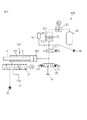
図1に、一般的なアルミ等の軽金属用ダイカストマシン100の図式的説明図を示す。後記する本発明の説明において、ダイカストマシン100の構成は詳しく説明するので、ここでは必要な事項のみを説明する。軽金属用ダイカストマシン100は通常、油圧式であり、作動油を射出シリンダ102のヘッド室に供給して、ピストンロッド4を駆動し、プランジャーロッド2を介してプランジャースリーブ7に貯められたアルミ(AL)溶湯15をプランジャーチップ1で押して、金型8,9内のキャビティ(空洞)12に射出充填して成形する。
FIG. 1 is a schematic explanatory diagram of a general
最近のダイカストでは、高真空(5kPa程度)で金型内のガスを抜くことで、ガス巻込み巣を削除し、射出速度を早くし、充填時間を短縮して、内部に発生する引け巣を少なくすることにより、ダイカストでの鋳造品の機械的性質が著しく改善されることが報告されている。最近のダイカストマシンでは、充填時間を短縮し溶湯の温度低下を最小にし鋳造品の品質を改良する要望が増大している。この場合の射出速度は、通常の2〜3m/secに対し5〜7m/secと約2.5倍になってくる(以上の速度の数値は実際の鋳造時の速度(実打ち速度)で、溶湯を金型に押し込んでいる状態での速度である)が、実際の鋳造現場では、ここまで速度を上げると、射出充填完了時の衝撃で、アルミ(AL)溶湯内にサージ圧が発生し、その為、型締装置が負け、金型がわずかに開きバリが発生する(金型の隙間から噴出した溶湯が固まってバリとなる)。また、ひどい時には湯噴きが発生し、どちらにしても「生産の継続ができなくなる。」という問題が発生する。 In recent die-casting, the gas in the mold is removed by high vacuum (about 5 kPa), thereby eliminating the gas entrapment nest, increasing the injection speed, shortening the filling time, and reducing the shrinkage nest generated inside. It has been reported that the mechanical properties of die castings are significantly improved by the reduction. In recent die casting machines, there is an increasing demand for improving the quality of cast products by shortening the filling time, minimizing the temperature drop of the molten metal. The injection speed in this case is 5 to 7 m / sec, which is about 2.5 times as high as the normal 2-3 m / sec (the above speed values are the actual casting speed (actual punching speed)). This is the speed when the molten metal is being pushed into the mold.) At actual casting sites, if the speed is increased to this point, a surge pressure is generated in the aluminum (AL) molten metal due to the impact at the completion of injection filling. Therefore, the mold clamping device is lost, the mold is slightly opened, and burrs are generated (the molten metal ejected from the gap between the molds is solidified to become burrs). Moreover, hot water squirts occur in severe cases, and in any case, the problem that “production cannot be continued” occurs.
従って、サージ圧を削減する種々の方法が従来提案されているが、これらの提案にはいずれも問題点が存在する。サージ圧は、図1で示す高速で走っている、プランジャーチップ1とプランジャーロッド2と射出カップリング3とピストンロッド4とピストンヘッド5の慣性力で発生するものと、高速でシリンダ6に流入してくる作動油の慣性と圧力で発生するものの複合として発生する。プランジャーチップ1とプランジャーロッド2とピストンロッド4とピストンヘッド5により充填完了の瞬間に現れるサージ圧が、バリ発生に最も大きな影響を与える。
Therefore, various methods for reducing the surge pressure have been proposed in the past, but all of these proposals have problems. The surge pressure is generated at the high speed shown in FIG. 1 due to the inertia force of the plunger tip 1, the
高速の実打ち速度性能を出すためには、空打ち時では(溶湯をスリーブ内に入れない、溶湯の流れ抵抗の無い状態)10m/sec超の性能を必要とする。もっとも、過酷なのは、この速度をわずか50mmの距離で立ち上げる必要があることでその為、高速速度立上げ時、大きな圧力を発生する様、射出シリンダと油圧回路が構成されている。そして、このまま充填を完了させると、充填完了時にキャビティ内の溶湯の圧力が一揮に上昇(サージ圧が発生)し金型が開き、湯噴きが発生し、鋳造ができない非常に危険な状態が発生する。 In order to obtain a high-speed actual striking speed performance, a performance exceeding 10 m / sec is required at the time of idling (a state where the molten metal is not put into the sleeve and there is no flow resistance of the molten metal). However, the most severe thing is that this speed needs to be raised at a distance of only 50 mm. Therefore, the injection cylinder and the hydraulic circuit are configured to generate a large pressure when the high speed speed is raised. If the filling is completed as it is, the pressure of the molten metal in the cavity rises at once when filling is completed (surge pressure is generated), the mold is opened, hot water is blown, and a very dangerous state where casting is impossible occurs. To do.
これを、防止する為、充填完了直前で射出ピストンを強制的に減速させる方式を採用している(図6参照)。(これに対し射出高速速度が2〜3m/sec仕様値のマシンでは、高速速度が低いこと、また、高速時の圧力も小さいため、型内の増大していく溶湯の流動抵抗とバランスし自然減速する為、充填完了時の衝撃値は小さくなり、バリや湯噴きは発生しにくい。)空打ち10m/secを超える高速速度仕様のマシンを超高速機と呼んでいるが、この超高速機での鋳造では悩ましい問題を抱えている。それは給湯機の給湯量の高度な精度を必要とすることで、給湯量が多いと充分減速される前に充填完了が起こり、サージ圧が発生し、給湯量が少ない場合、湯先が飛び、不連続の充填となり、湯境不良やひどい時はガスの巻込み不良が発生する。この給湯量が不足し減速が早く効き過ぎた場合の不良発生のメカニズムについて図7で図解している。ところが、給湯機の給湯精度を上げることは至難の業で、なかなか解決の方法が見つからない。 In order to prevent this, a method of forcibly decelerating the injection piston immediately before completion of filling is adopted (see FIG. 6). (On the other hand, in a machine with a high injection speed of 2 to 3 m / sec, the high speed is low and the pressure at high speed is small, so it balances with the increasing flow resistance of the molten metal in the mold. Because of the slowdown, the impact value at the completion of filling is reduced, and burrs and hot water sprays are less likely to occur.) A machine with a high speed specification exceeding 10m / sec is called an ultra high speed machine. Casting in Japan has an annoying problem. It requires a high degree of accuracy in the amount of hot water supplied by the water heater, and if the amount of hot water is large, filling is completed before it is sufficiently decelerated, surge pressure is generated, and if the amount of hot water is small, the hot water will fly, It becomes discontinuous filling, and poor entrainment of gas occurs when the hot water boundary is bad or bad. FIG. 7 illustrates the mechanism of occurrence of defects when the amount of hot water supply is insufficient and deceleration is effected too quickly. However, raising the hot water supply accuracy of a water heater is a difficult task, and it is difficult to find a solution.
図6のグラフにおいて、溶湯湯量の増減により、充填完了時のプランジャーチップ先端位置がどのように変わるかを示している。溶湯湯量が適正である(予定通りである)場合の完了位置を「理想の完了位置」として示している(破線)。給湯量が多い場合には、充填完了位置は、ゲートから離れるので、1点鎖線で示す位置になる。湯量が少ない場合には、充填完了位置は、ゲートに近づくので、2点鎖線で示す位置になる。このように、溶湯湯量の増減によって、充填完了位置は、それぞれ異なり、それに応じて、サージ圧が発生したり、湯先が飛ぶという問題が起こる。一方、給湯機の給湯精度を上げることは困難であり、また給湯量を把握することも容易ではないので、給湯量を把握して減速開始位置を調整することも困難となる。 In the graph of FIG. 6, it is shown how the position of the tip of the plunger tip at the time of filling is changed by increasing / decreasing the amount of the molten metal. The completion position when the amount of molten metal is appropriate (as planned) is shown as an “ideal completion position” (broken line). When the amount of hot water supply is large, the filling completion position is away from the gate, and thus is a position indicated by a one-dot chain line. When the amount of hot water is small, the filling completion position is close to the gate, and thus becomes a position indicated by a two-dot chain line. As described above, the filling completion position differs depending on the increase / decrease in the amount of the molten metal, and accordingly, there arises a problem that a surge pressure is generated or the molten metal tip flies. On the other hand, it is difficult to increase the hot water supply accuracy of the water heater, and it is not easy to grasp the amount of hot water supply, so it is difficult to grasp the amount of hot water and adjust the deceleration start position.
給湯量の増減に係わらず、サージ圧を削減する方法として、高圧用と低圧用のアキュムレータを設ける構成からなる案(例えば、特許文献1参照)を、本願の出願人は、既に提案しているが、本発明はこの案とは異なる。 The applicant of the present application has already proposed a proposal (see, for example, Patent Document 1) that includes a high pressure accumulator and a low pressure accumulator as a method for reducing surge pressure regardless of the amount of hot water supply. However, the present invention is different from this scheme.
本願の出願人は、更に別の案を提案している(例えば、特許文献2参照)。この案では、高速射出時において、射出シリンダ102を駆動する油圧の駆動力として、ガスボトルに充填された高圧ガスを使用する。高圧ガスで作動油を押圧する場合、高圧ガスは膨張するので、ガス圧力は低下する。そして、この駆動ガス圧力の圧力降下を利用して、射出シリンダのストロークエンド付近で発生する溶湯のサージ圧を抑制し、サージ圧の発生を防止する。特許文献2において、2つの案が提案されており、第1の案では、ガスボトルの容量を変更可能にして、鋳造品のタイプにより最適のガスボトル容量を選択するものである。第2の案では、ガスボトルの出口側に可変式絞り弁を設けて絞りの開度を調整するものである。いずれの案も、高速射出速度を実現しつつ、サージ圧の発生を防止すると共に、高品質な製品の成形を可能にしようというものである。
The applicant of the present application has proposed another proposal (for example, see Patent Document 2). In this scheme, high-pressure gas filled in a gas bottle is used as a hydraulic driving force for driving the
上記の従来案の油圧回路を図8に示す。図8の油圧回路では、ガスボトルの出口側に可変式絞り弁82を設けている(上記の第2の案)。図8の油圧回路は、後述する本発明の油圧回路との共通点も多いので、その説明は、最小限のものとする。図8において、射出用ピストンアキュムレータ20のピストンを移動させて作動油を射出シリンダ102のヘッド室16Hに供給して、射出ピストン4を駆動し、高速射出をおこなう。射出用ピストンアキュムレータ20のガス室217は、ガスボトル80に連絡しており、ガス室217とガスボトル80の間には、モータ駆動式であることが好ましい可変式絞り弁が設けられており、この絞り弁は、充填力パターン調整バルブ82と呼ばれている。高速射出段階において、この充填力パターン調整バルブ82の開度を調整することにより、流路抵抗による圧力降下を生じさせてサージ圧の発生を防止する。
FIG. 8 shows the conventional hydraulic circuit. In the hydraulic circuit of FIG. 8, a
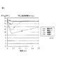
図8の油圧回路503において、昇圧用ピストンアキュムレータ23が具備されており、高速射出段階から昇圧段階への移行時に昇圧開閉弁35を開いて、昇圧用ピストンアキュムレータ23からの作動油を射出シリンダ102のヘッド室16Hに導入して、溶湯に作用する圧力を上昇させる(即ち、昇圧する)。高速射出の完了時に昇圧のための回路に切り替えるのは、ガスボトル80からのガスラインの圧力低下による圧力の低下を素早く所定の圧力に上昇させる(昇圧する)ためであり、この昇圧速度が遅いと圧力の低い状態で溶湯の凝固が始まり巣の発生原因となる。図8の油圧回路において、充填力パターン調整バルブ82によりガス量を絞った場合の射出用ピストンアキュムレータのガス圧の復帰の経時変化を図4に示す。
In the
目的の出力(圧力)ダウンをさせる場合、絞り弁の開度は5〜10mm程度となり、図4で見ると点線の部分になる。ダイカストマシンに要求される昇圧時間は20〜50msecである。しかしこの場合、射出用ピストンアキュムレータのガス圧復帰時間は30〜200msec要しており、間に合っていない。したがって、図8の従来技術の油圧回路では、別に昇圧用ピストンアキュムレータを設け、高速充填が完了する寸前で昇圧側に回路を切替え、昇圧能力を出している。その場合、射出能力の連続性を守る為に、昇圧用開閉弁を開き、少し遅れて射出用開閉弁を閉じるという制御を行っている。射出用開閉弁を閉じるのが早すぎると射出圧が一旦下がりそこから再上昇をしてくるという特性になり、圧力の不連続性がおこる。また、射出用開閉弁を閉じるのが遅すぎると、昇圧時間遅れが大きくなり、ひけ巣等、同じく鋳造品の品質に問題が起こってくる。この従来技術の油圧回路では、この微妙な切り替え遅れ時間の最適値を求め、バラツキが最小になるように制御することが必要となる。 When the target output (pressure) is reduced, the opening of the throttle valve is about 5 to 10 mm, which is a dotted line portion in FIG. The pressurization time required for the die casting machine is 20 to 50 msec. However, in this case, the gas pressure recovery time of the injection piston accumulator is 30 to 200 msec, which is not in time. Therefore, in the prior art hydraulic circuit of FIG. 8, a boosting piston accumulator is provided separately, and the circuit is switched to the boosting side just before the high-speed filling is completed to increase the boosting capability. In that case, in order to protect the continuity of the injection capacity, control is performed such that the boosting on-off valve is opened and the injection on-off valve is closed after a short delay. If the on-off valve for injection is closed too early, the injection pressure drops once and then rises again, causing pressure discontinuity. Also, if the injection on / off valve is closed too late, the pressure increase time delay becomes large, and a problem occurs in the quality of the cast product, such as a sinkhole. In this conventional hydraulic circuit, it is necessary to obtain an optimum value of the delicate switching delay time and to perform control so that the variation is minimized.
本発明は、上述した事情に鑑みなされたもので、高速射出成形可能なダイカスト鋳造方法又はダイカストマシンにおいて、サージ圧の発生を削減して、バリの発生や湯噴き、又は湯先の飛びを防止し、更に鋳造品質のバラツキを最も少なくするとともに、そのための複雑な制御を改善とすることを目的とする。
本発明は更に、昇圧用ピストンアキュムレータ等を削除することにより装置を簡素化して、コストダウンを図ることを別の目的とする。
The present invention has been made in view of the above-described circumstances, and in a die casting method or die casting machine capable of high-speed injection molding, the generation of surge pressure is reduced to prevent generation of burrs, hot water spray, or jumping of the hot water tip. Furthermore, the object is to minimize the variation in casting quality and to improve the complicated control for that purpose.
It is another object of the present invention to simplify the apparatus by eliminating a boosting piston accumulator and the like, thereby reducing the cost.
本発明の第1の形態のダイカストマシン(100)は、上述した目的を達成するために、製品を鋳造成形する金型(101)と;それ自体が具備するピストン(13)を移動させることにより、金型(101)に溶湯(15)を射出するための射出シリンダ(102)であって、作動油が供給されるとそれにより、ピストン(13)を金型(101)に向かって前進させる、ヘッド室(16H)と、作動油が供給されるとそれにより、ピストン(13)を金型(101)から遠ざかるように後退させる、ロッド室(16R)とを具備する、射出シリンダ(102)と;射出シリンダ(102)に作動油を供給するための油圧装置(303,403)とを具備する。油圧装置(303,403)は、射出シリンダ(102)のピストン(13)を押圧する作動油を射出シリンダ(102)に供給する射出用ピストンアキュムレータ(20)であって、作動油を収容する作動油室(218)と、ガスを収容するガス室(217)とが、射出用ピストンアキュムレータ(20)のピストン(211)により気密に仕切られることにより、内部に形成される、射出用ピストンアキュムレータ(20)と;射出用ピストンアキュムレータ(20)の前記ガス室(217)に流体連絡するように設置されて、ガス室(217)へガスを供給することにより、射出用ピストンアキュムレータ(20)のピストン(211)を押圧して作動油を駆動する、ガスボトル(80)と;射出用ピストンアキュムレータ(20)のガス室(217)とガスボトル(80)との間に配置されて、ガスの流れを調整する、充填力パターン調整バルブ(82)と;射出用シリンダ(102)のピストン(13)の射出速度を制御するための高速速度調整バルブ(31)と;射出用ピストンアキュムレータ(20)の作動油室(218)の圧力を検出する圧力検出器(50)とを具備する。充填力パターン調整バルブ(82)は、その開度が可変で設定可能なサーボモータバルブであり、圧力検出器(50)の検出した圧力により、充填力パターン調整バルブ(82)の開度をフィードバック制御して、射出シリンダ(102)への作動油の充填力を調整できることを特徴とする。 In order to achieve the above-mentioned object, a die casting machine (100) according to a first aspect of the present invention moves a mold (101) for casting a product and a piston (13) included in the mold (101). An injection cylinder (102) for injecting molten metal (15) into the mold (101), and when hydraulic oil is supplied, thereby causing the piston (13) to advance toward the mold (101). An injection cylinder (102) comprising a head chamber (16H) and a rod chamber (16R) which, when supplied with hydraulic oil, causes the piston (13) to retract away from the mold (101). And a hydraulic device (303, 403) for supplying hydraulic oil to the injection cylinder (102). The hydraulic device (303, 403) is an injection piston accumulator (20) that supplies hydraulic oil that presses the piston (13) of the injection cylinder (102) to the injection cylinder (102), and that operates to store the hydraulic oil. An injection piston accumulator (internally formed) is formed by an oil chamber (218) and a gas chamber (217) for containing gas being hermetically partitioned by the piston (211) of the injection piston accumulator (20). 20) and; the piston of the injection piston accumulator (20) installed in fluid communication with the gas chamber (217) of the injection piston accumulator (20) and supplying gas to the gas chamber (217). (211) is pressed to drive the hydraulic oil, the gas bottle (80); and the injection piston accumulator (20) A filling force pattern adjusting valve (82) disposed between the gas chamber (217) and the gas bottle (80) to adjust the gas flow; and the injection speed of the piston (13) of the injection cylinder (102) And a pressure detector (50) for detecting the pressure of the hydraulic oil chamber (218) of the injection piston accumulator (20). The filling force pattern adjustment valve (82) is a servo motor valve whose opening degree is variable and can be set, and the opening degree of the filling force pattern adjustment valve (82) is fed back by the pressure detected by the pressure detector (50). It is possible to control and adjust the filling force of hydraulic oil to the injection cylinder (102).
好適な形態において、油圧装置(303,403)は、溶湯(15)の射出速度を検出するために射出シリンダ(102)のピストン(13)の速度を検出する射出速度検出器を更に具備しており、高速速度調整バルブ(31)を、射出速度によりフィードバック制御して、高速速度調整バルブ(31)の開度を調整できる。また、高速速度調整バルブ(31)は、射出シリンダ(102)のヘッド室(16H)の入口側、及び射出シリンダ(102)のロッド室(16H)の出口側のいずれか一方に配置される。 In a preferred embodiment, the hydraulic device (303, 403) further comprises an injection speed detector for detecting the speed of the piston (13) of the injection cylinder (102) in order to detect the injection speed of the molten metal (15). The high-speed speed adjusting valve (31) can be feedback-controlled by the injection speed to adjust the opening degree of the high-speed speed adjusting valve (31). Further, the high speed speed adjusting valve (31) is arranged on either the inlet side of the head chamber (16H) of the injection cylinder (102) or the outlet side of the rod chamber (16H) of the injection cylinder (102).
本発明の別の形態は、前記形態1に記載のダイカストマシン(100)を使用するダイカスト鋳造方法を提供する。このダイカスト鋳造方法は、射出シリンダ(102)内の溶湯(15)を低速で押圧する、低速射出段階と、射出シリンダ(102)内の溶湯(15)を高速で押圧して金型(101)内に射出する、高速射出段階と、金型(101)内の溶湯(15)を所定の圧力まで加圧する、昇圧段階と、昇圧段階において加圧された溶湯(15)の圧力を保持する、圧力保持段階と、を具備する。ダイカスト鋳造方法の昇圧段階において、充填力パターン調整バルブ(82)の開度は、圧力検出器(50)の検出圧力をフィードバック信号として使用して、予め設定された作動油の圧力上昇パターンおよび最終圧力に従うようにフィードバック制御される。更に、油圧装置(303)は、溶湯(15)の射出速度を検出するために射出シリンダ(102)のピストン(13)の速度を検出する射出速度検出器を更に具備しており、低速射出段階及び高速射出段階において、高速速度調整バルブ(31)の開度は、射出速度がそれぞれの所定値となるようにフィードバック制御されることが好ましい。 Another embodiment of the present invention provides a die casting method using the die casting machine (100) described in the first embodiment. In this die casting method, the molten metal (15) in the injection cylinder (102) is pressed at a low speed, and the molten metal (15) in the injection cylinder (102) is pressed at a high speed to mold (101). Injecting into the high-speed injection stage, pressurizing the molten metal (15) in the mold (101) to a predetermined pressure, maintaining the pressure of the molten metal (15) pressurized in the pressurizing stage and the pressurizing stage; A pressure holding stage. In the pressurization stage of the die casting method, the opening degree of the filling force pattern adjustment valve (82) is determined by using the pressure detected by the pressure detector (50) as a feedback signal and a preset hydraulic oil pressure rise pattern and final value. Feedback controlled to follow the pressure. Further, the hydraulic device (303) further includes an injection speed detector for detecting the speed of the piston (13) of the injection cylinder (102) in order to detect the injection speed of the molten metal (15). In the high-speed injection stage, the opening degree of the high-speed speed adjusting valve (31) is preferably feedback controlled so that the injection speed becomes a predetermined value.
特には、高速射出成形可能なダイカスト鋳造法又はダイカストマシン(鋳造機械)において、高速速度調整バルブ及び充填力パターン調整バルブのフィードバック制御を行うことにより、ガスの膨張による駆動作動油の圧力ドロップを利用して、複雑な制御を行うことなく、スタート時は高圧力で、短い時間で高速速度を立ち上げ、充填完了前までにはその圧力を最適値まで下げ、金型内溶湯の流動抵抗による自然減速でその高速速度値を下げ、充填完了時の衝撃を緩和し、高速射出成形を可能とすると共に、その際の金型のキャビティにおけるアルミ溶湯のサージ圧の発生を抑止し、バリの発生や湯噴き、又は湯先の飛びを防止する。
更に、例え溶湯の給湯量にバラツキがあったとしても、金型に流入した溶湯の流動抵抗により充填完了位置の手前ではプランジャーは自然減速されるので、金型内での減速位置は同じになり、サージ圧の発生を抑止し、バリの発生や湯噴き、又は湯先の飛びを防止可能である。
In particular, in a die casting casting method or die casting machine (casting machine) capable of high-speed injection molding, feedback control of the high-speed speed adjustment valve and filling force pattern adjustment valve is used to use the pressure drop of the driving hydraulic oil due to gas expansion Without starting complicated control, start up at high pressure at a high pressure in a short time, start up the high speed in a short time, reduce the pressure to the optimum value before filling, and naturally by the flow resistance of the molten metal in the mold Deceleration reduces the high speed value, mitigates impact at the completion of filling, enables high speed injection molding, suppresses the occurrence of surge pressure of molten aluminum in the mold cavity at that time, Prevents hot water spraying or hot water splashing.
Furthermore, even if there is a variation in the amount of hot water supplied to the molten metal, the plunger is naturally decelerated just before the filling completion position due to the flow resistance of the molten metal flowing into the mold, so the deceleration position in the mold is the same. Thus, it is possible to suppress the generation of surge pressure, and to prevent the occurrence of burrs, spraying of hot water, or jumping of hot water.
従来必要であった、昇圧用ピストンアキュムレータ及びその周辺の制御弁類を削除することが出来る。また、構成部品及び弁類が不要になったこと等により、複雑な制御方法を改善すると共に、装置のコストダウウンをすることが出来る。 The boosting piston accumulator and its surrounding control valves, which were necessary in the past, can be deleted. In addition, since the components and valves are no longer necessary, a complicated control method can be improved and the cost of the apparatus can be reduced.
上記の本発明の説明において、カッコ()内の記号又は数字は、以下に示す実施の形態との対応を示すために添付される。 In the above description of the present invention, symbols or numbers in parentheses () are attached to show correspondence with the embodiments described below.
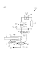
以下、図面に基づいて本発明の実施の形態のダイカストマシン(装置)を詳細に説明する。図1は既に説明したように、一般的なアルミ等の軽金属用ダイカストマシン100の金型101及び射出シリンダ102付近の部分の図式的説明図であり、本発明のダイカストマシン100も同様な金型101及び射出シリンダ102を具備する。図2は、本発明に係るダイカストマシン100の油圧装置303の油圧回路の第1の実施の形態の系統図である。
Hereinafter, a die casting machine (apparatus) according to an embodiment of the present invention will be described in detail with reference to the drawings. FIG. 1 is a schematic explanatory view of a portion near a
まず図1を参照すると、本発明のダイカストマシン(鋳造装置)100の金型101及び射出シリンダ102が図式的に示されている。図1については、従来技術の説明で既に説明したが、ここでは、より詳しく説明する。図1のダイカストマシン100は通常、アルミ等の軽金属の製品を鋳造する。ダイカストマシン(鋳造装置)100は、金型101と、射出シリンダ102とを具備しており、金型101においては、対向する一対の固定プラテン10と可動プラテン11との間に固定金型8と可動金型9が設けられており、固定金型8と可動金型9は、図1に示すごとく係合することにより、その間にキャビティ(空洞)12を形成し、キャビティ12にアルミ(AL)溶湯15が射出・充填されて鋳造成形品が製造される。アルミ溶湯15を射出するために、射出シリンダ102が設けられており、固定プラテン10にはアルミ溶湯15が貯められるプランジャースリーブ7が設けられており、プランジャースリーブ7は、固定プラテン10及び固定金型8を貫通して、キャビティ12に流体連絡する。
First, referring to FIG. 1, a
本実施の形態において、射出シリンダ102は、アルミ溶湯を射出するための油圧駆動の往復動ピストン/シリンダである。射出シリンダ102は、シリンダ6とピストン13とを具備する。ピストン13は図1に示すように、プランジャースリーブ7に係合する。ピストン13は、図1において左端にピストンヘッド5を具備し、そのピストンヘッド5と一体化しているピストンロッド4に射出カップリング3でプランジャーロッド2が連結され、その先にプランジャーチップ1が取り付けられている。プランジャーチップ1は、プランジャースリーブ7内に嵌合し、プランジャースリーブ7内で往復動して、プランジャースリーブ7内のアルミ溶湯15を圧送することにより、アルミ溶湯15を射出充填する。本実施の形態において、射出シリンダ102は、油圧式であるので、作動油をシリンダ6のヘッド側に供給して、ピストンヘッド5及びピストンロッド4を駆動し、プランジャースリーブ7に貯められたアルミ(AL)溶湯15をプランジャーチップ1で押して、固定金型8,9内のキャビティ(空洞)12に射出充填して鋳造成形する。
In the present embodiment, the
図2は、射出シリンダ102を駆動する本発明の第1の実施の形態の油圧装置303の油圧回路を図解的に示す。射出シリンダ102のヘッド室16Hの接続口ラインには、出口切替バルブ21を介して高速射出用に大流量を排出可能な射出用ピストンアキュムレータ(ACC)20が流体連絡するように設けられている。一般的に円筒状の射出用ピストンアキュムレータ20は、ピストンアキュムレータ20内を摺動して往復動する、ピストン211により2つの室に気密に区切られており、一方は、作動油が収容される作動油室218であり、もう一方は、ガスが収容されるガス室217である。ガス室217には、ガスボトル80から高圧ガスが供給されて、ピストン211を押圧して作動油室218の作動油を油圧装置303の油圧回路、即ちここでは最終的に射出シリンダ102のヘッド室16Hに供給する。本実施の形態においては、ガス室217は、図2に示すように、充填力パターン調整バルブ82を介してガスボトル80に流体連絡する。本実施の形態の油圧装置303において、図2に示すように、射出シリンダ102のヘッド室16Hは更に、射出用切替バルブ26を介してタンク40に流体連絡する。射出用切替バルブ26は、3つの切替位置を有する電磁切替弁であることが好ましく、図2に示すように、一方の側の接続口は、射出シリンダ102のヘッド室16Hの接続口(入口側)に接続しており、もう一方の側の接続口はタンク40に接続する。
FIG. 2 schematically shows a hydraulic circuit of the
射出シリンダ102のロッド室16Rの接続口(出口側)ラインは、射出速度を制御する高速速度調整バルブ31を介してタンク40またはポンプ圧供給口55に流体連絡する(メータ・アウト回路)。これとは別に、射出速度を制御する高速速度調整バルブ31は、射出シリンダ102の上流側(入口側)(即ち、射出シリンダ102と射出ピストンアキュムレータ20との間)に設置されても良い(メータ・イン回路)。本実施の形態においては、射出用ピストンアキュムレータ20の作動油室218の出口側(下流)には、圧力検出器50が備えられて、射出用ピストンアキュムレータ20の作動室の出口側の作動油圧力を検知する。この検知された圧力(油圧)は、圧力信号として、制御装置(図示されない)に送られ、さらに充填力パターン調整バルブ82にフィードバック信号が送られる。
The connection port (outlet side) line of the
図2に示す油圧装置303の各バルブについて説明する。高速速度調整バルブ31は、全開位置から全閉位置まで連続的に開度を変化可能なモータ駆動弁であることが好ましい。充填力パターン調整バルブ82は、射出用ピストンアキュムレータ20へ供給するガス量を調整するためのバルブであり、10〜20msecの開状態から全閉まで調整可能なサーボバルブであることが好ましい。射出用切替バルブ26については、既に説明したが、3つの位置は、図2に図式的に示すようにそれぞれ、流路閉鎖位置と、順流路開位置と、交差流路開位置とである。出口切替バルブ21は、開と閉を切り替える電磁式切替弁であることが好ましい。
Each valve of the
次に本実施の形態のダイカストマシン100及びその油圧装置303の作動について説明する。ダイカストマシン100の全体的な作動は、通常のダイカストマシンと同様であるので概略の説明とする。先ず、プランジャースリーブ7にAL溶湯15を供給し、その後溶湯温度が低下しないように遅滞なく射出動作が実施される。先ず、低速でピストン13により溶湯15を金型101のキャビティ12に向かって押す(低速射出段階)。この際のピストン13の駆動は、本実施の形態においては、充填力パターン調整バルブ82を開くと共に出口切替バルブ21を開にし、高速速度調整バルブ31の絞り開度を調整するように操作して、ガスボトル80の圧力により射出用ピストンアキュムレータ20のピストン211を移動させて作動油をヘッド室16Hに供給することにより実施される。また、高速速度調整バルブ31の絞り開度の調整(開度小)は、射出ピストン4の速度を射出速度検出器(図示されない)により検出し、この速度が所定速度になるように制御装置(図示されない)を介してフィードバック制御することにより実施する。充填力パターン調整バルブ82の開度は、所望の射出圧力となる開度(予め決められた開度)に設定される。ピストン13が所定ストローク移動後又はピストン13が所定位置に到達したことにより、低速射出段階から高速射出段階に切り替わる。
Next, the operation of the
次に、所定の高速の射出速度となるように、やはり射出速度検出器により、高速速度調整バルブ31の開度(開度大)を制御装置(図示されない)を介してフィードバック制御して、高速でピストン13を駆動する(高速射出段階)。この高速射出段階で、キャビティ12内は溶湯15で充填される。次に、充填力パターン調整バルブ82を調整して、ガスボトル80からガス室217へ高圧のガスを供給することにより、ヘッド室16Hに射出用ピストンアキュムレータ20から更に高圧の作動油を導入して、キャビティ内の圧力を、所定の時間で所定圧力まで昇圧する(昇圧段階)。昇圧段階において、高速速度調整バルブ31は、全開するように調整され、充填力パターン調整バルブ82は、圧力検出器50の検出圧力をフィードバック信号として使用して、予め設定された圧力上昇パターンおよび最終圧力を実現するようにフィードバック制御される。この昇圧段階において主に、本発明の新規な構成が機能する。
Next, the opening speed (large opening degree) of the high-speed
次に、所定圧力を所定時間の間保持する(加圧保持段階)。加圧保持段階において、充填力パターン調整バルブ82は原則的には全閉であるが、圧力検出器50が圧力低下を検出した場合、若干開かれ圧力の制御が行なわれる。高速速度調整バルブ31は全開であるように設定される。その後、製品を取り出す(型開き段階)。加圧保持段階後において、高速速度調整バルブ31を調整して、ポンプ圧供給口55から射出シリンダ102のロッド室16Rに作動油を供給して、射出ピストン4を後退させて原点復帰させる。その後、充填力パターン調整バルブ82を所望の開度に開き、別の油圧供給ライン56から、射出用ピストンアキュムレータ20の作動油室218に作動油を供給して、ガスボトル80を蓄圧する。以上が、概略の射出成形工程である。上記における一連の制御は、制御装置(図示されない)を介して行なわれる。
Next, a predetermined pressure is held for a predetermined time (pressurization holding stage). In the pressurization and holding stage, the filling force
本実施の形態によれば、鋳造する金型の特性(キャビティの容量や投影面積)に合わせて、高速速度調整バルブ31と充填力パターン調整バルブ82をフィードバック制御して、高速射出速度を実現すると共に、高速射出時において起こるガスの膨張で発生する圧力降下(ドロップ)を利用して自然減速し溶湯のサージ圧等の発生を防止し、更に動力源としてガスボトル80のみで低速射出、高速射出及び昇圧を行うことができる。
According to the present embodiment, high-speed injection speed is realized by feedback control of the high-speed
上記の出願人の先願(特許技術文献2)において、実際のオペレーションにおいては、品質の良い鋳造品が成形できる射出速度、射出圧力変化パターン、最終充填力(射出シリンダのヘッド室側の油圧:Ph)、保持圧等を決定するための方法として、試し打ちを実施することが好ましいと記載しているが、このことは本願においても同様であるので、この試し打ちの詳細については省略する。 In the above-mentioned prior application (Patent Technical Document 2) of the applicant, in actual operation, the injection speed, injection pressure change pattern, final filling force (hydraulic pressure on the head chamber side of the injection cylinder: Ph), it is described that it is preferable to perform trial hitting as a method for determining the holding pressure and the like. However, since this is the same in the present application, details of this trial hitting are omitted.
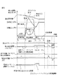
図5に、本実施の形態における、射出速度(v)及び射出圧力(PH)等の時間変化及びその際のピストンロッド、各バルブ等の状態を表わすチャートを示す。図5中において、PHは射出圧力、Pmは保持圧力を示す。低速射出段階は、時間t0〜t1間であり、高速射出段階は、時間t1〜t2間であり、昇圧段階は、時間t2〜t3間であり、加圧保持段階は、時間t3〜t4間である。t2において、高速射出段階から昇圧段階への切替(即ち、高速速度調整バルブ31の切替と、充填力パターン調整バルブ82の切替)は、ヘッド室16H及びロッド室16Rに設けられた圧力検出器の検出圧力(Ph)により実施される。射出ピストン4の動作、各弁の動作等については図5を見れば十分に理解可能であるので、詳細な説明は省略する。メータアウト制御の場合の射出圧力(PH)は次式のように表現できる。
射出圧力(PH)=Ph−(Sr/Sh)×Pr
ここで、Ph:ヘッド室16Hの圧力、Pr:ロッド室16Rの圧力、Sh:ヘッド室16H側の面積、Sr:ロッド室16R側の面積である。
FIG. 5 shows a chart showing temporal changes in the injection speed (v), injection pressure (PH), etc., and states of the piston rod, each valve, etc. at that time in the present embodiment. In FIG. 5, PH represents the injection pressure, and Pm represents the holding pressure. The low-speed injection stage is between times t0 and t1, the high-speed injection stage is between times t1 and t2, the boosting stage is between times t2 and t3, and the pressurization holding stage is between times t3 and t4. is there. At t2, switching from the high-speed injection stage to the boosting stage (that is, switching of the high-speed
Injection pressure (PH) = Ph− (Sr / Sh) × Pr
Here, Ph: pressure in the
図3は、本発明に係るダイカストマシン100の油圧装置の第2の実施の形態の系統図である。以下、第1の実施の形態との相違点についてのみ説明する。第2の実施の形態の油圧装置403は、第1の実施の形態の油圧装置303に対して、高速速度調整バルブ31の位置が異なっている。即ち、図3の油圧装置403の油圧回路において、高速速度調整バルブ31は、射出シリンダ102のヘッド室16Hの入口側(上流)に設置される(メータ・イン回路)が、一方、図2の油圧装置303の油圧回路においては、高速速度調整バルブ31は、射出シリンダ102のロッド室16Rの出口側(下流)に設置される(メータ・アウト回路)。この構成の相違に伴い、図3の第2の実施の形態においては、射出用切替バルブ26は、ロッド室16Rの出口側に配置され、タンク40及びポンプ圧供給口55への系統もそれに応じて変更されている。
FIG. 3 is a system diagram of a second embodiment of the hydraulic apparatus of the
図3の第2の実施の形態において、ロッド室16Rがタンク40に導通した場合に、ロッド室圧力Prは実質的にゼロであるので、射出圧力PHは、ヘッド室圧力Phと等しくなる。油圧装置403において、その他の構成は基本的に、図2に示す第1の実施の形態の油圧装置303と同様であり、ダイカストマシン100の作動方法も第1の実施の形態と実質的に同様である。
In the second embodiment of FIG. 3, when the
次に上記実施の形態の効果及び作用について説明する。本発明の第1の実施の形態のダイカストマシンにより以下の効果が期待できる。
・特には、高速射出成形可能なダイカスト鋳造法又はダイカストマシン(鋳造機械)において、高速速度調整バルブ31及び充填力パターン調整バルブ82のフィードバック制御を行うことにより、ガスの膨張による駆動作動油の圧力ドロップを利用して、複雑な制御を行うことなく、スタート時は高圧力で、短い時間で高速速度を立ち上げ、充填完了前までにはその圧力を最適値まで下げ、金型内溶湯の流動抵抗による自然減速でその高速速度値を下げ、充填完了時の衝撃を緩和し、高速射出成形を可能とすると共に、その際の金型のキャビティにおけるアルミ溶湯のサージ圧の発生を抑止し、バリの発生や湯噴き、又は湯先の飛びを防止する。
・例え溶湯の給湯量にバラツキがあったとしても、サージ圧の発生を抑止し、バリの発生や湯噴き、又は湯先の飛びを防止可能である。
・従来必要であった、射出用ピストンアキュムレータ20とは別途必要であった昇圧用ピストンアキュムレータ及びその周辺の制御弁類を削除することが出来る。
・構成部品及び弁類が不要になったこと等により、複雑な制御方法を改善すると共に、装置のコストダウウンを図ることが出来る。
Next, effects and operations of the above embodiment will be described. The following effects can be expected from the die casting machine according to the first embodiment of the present invention.
In particular, in the die casting method or die casting machine (casting machine) capable of high-speed injection molding, feedback control of the high-speed
-Even if there is a variation in the amount of hot water supplied to the molten metal, it is possible to suppress the generation of surge pressure and prevent the occurrence of burrs, hot water spray, or jumping of the hot water tip.
The step-up piston accumulator and the control valves around it, which were necessary separately from the
・ By eliminating the need for components and valves, it is possible to improve the complicated control method and reduce the cost of the apparatus.
本発明の第2の実施の形態のダイカストマシンにより、第1の実施の形態と同様の効果が期待できる。 With the die casting machine of the second embodiment of the present invention, the same effect as that of the first embodiment can be expected.
上記において記載した、あるいは添付図面に示した実施の形態の油圧回路において、説明を分かり易くするために、基本的に最低限の構成要素だけが記載されているが、装置の機能、制御、配置等に応じて必要な、弁、こし器、センサ等の構成要素が追加されても良い。 In the hydraulic circuit of the embodiment described above or shown in the attached drawings, for the sake of easy understanding, only the minimum components are basically described, but the function, control, and arrangement of the device are described. Components such as a valve, a strainer, and a sensor that are necessary depending on the above may be added.
上記の実施の形態において、鋳造(溶湯)の材料はアルミニウムであると記載されているが、これ以外の材料であっても良い。 In the above embodiment, the material of casting (molten metal) is described as aluminum, but other materials may be used.
本明細書及び例えば図3,4等に記載される数値について、説明の便宜上使用したものであって、特に本発明がこれらの数値によって限定されることはなく、例えば、ダイカストマシンの型式が変わればこれらの数値が変わることがあり得る。 The numerical values described in this specification and, for example, FIGS. 3 and 4 are used for convenience of explanation, and the present invention is not particularly limited by these numerical values. For example, the type of the die casting machine is changed. These numbers can change.
上記の実施の形態は本発明の例であり、本発明は、該実施の形態により制限されるものではなく、請求項に記載される事項によってのみ規定されており、上記以外の実施の形態も実施可能である。 The above-described embodiment is an example of the present invention, and the present invention is not limited by the embodiment, but is defined only by matters described in the claims, and other embodiments than the above are also possible. It can be implemented.
アルミニウム製品を鋳造するダイカストマシンにおける射出装置の油圧回路に適用可能で、製品の品質向上や生産性の効率化に貢献できる。 It can be applied to the hydraulic circuit of an injection device in a die casting machine for casting aluminum products, and can contribute to improving product quality and improving productivity.
1 プランジャーチップ
2 プランジャーロッド
3 射出カップリング
4 ピストンロッド
5 ピストンヘッド
6 シリンダ
16H ヘッド室
16R ロッド室
7 プランジャースリーブ
8 固定金型
9 可動金型
10 固定プラテン
11 可動プラテン
12 キャビティ(空洞)
13 ピストン
15 (アルミ)溶湯
20 射出用ピストンアキュムレータ
21 出口切替バルブ
26 射出用切替弁
31 高速速度調整バルブ
40 タンク
80 ガスボトル
82 充填力パターン調整バルブ
100 ダイカストマシン
101 金型
102 射出シリンダ
211 ピストン
217 ガス室
218 作動油室
303 油圧装置
403 油圧装置
DESCRIPTION OF SYMBOLS 1
13 piston 15 (aluminum)
Claims (5)
それ自体が具備するピストン(13)を移動させることにより、前記金型(101)に溶湯(15)を射出するための射出シリンダ(102)であって、作動油が供給されるとそれにより、前記ピストン(13)を前記金型(101)に向かって前進させる、ヘッド室(16H)と、作動油が供給されるとそれにより、前記ピストン(13)を前記金型(101)から遠ざかるように後退させる、ロッド室(16R)とを具備する、射出シリンダ(102)と;
前記射出シリンダ(102)に作動油を供給するための油圧装置(303,403)と;
を具備するダイカストマシン(100)において、
前記油圧装置(303,403)は、
前記射出シリンダ(102)の前記ピストン(13)を押圧する作動油を前記射出シリンダ(102)に供給する射出用ピストンアキュムレータ(20)であって、作動油を収容する作動油室(218)と、ガスを収容するガス室(217)とが、前記射出用ピストンアキュムレータ(20)のピストン(211)により気密に仕切られることにより、内部に形成される、射出用ピストンアキュムレータ(20)と;
前記射出用ピストンアキュムレータ(20)の前記ガス室(217)に流体連絡するように設置されて、前記ガス室(217)へガスを供給することにより、前記射出用ピストンアキュムレータ(20)のピストン(211)を押圧して作動油を駆動する、ガスボトル(80)と;
前記射出用ピストンアキュムレータ(20)の前記ガス室(217)と前記ガスボトル(80)との間に配置されて、ガスの流れを調整する、充填力パターン調整バルブ(82)と;
前記射出シリンダ(102)のピストン(13)の射出速度を制御するための高速速度調整バルブ(31)と;
前記射出用ピストンアキュムレータ(20)の作動油室(218)の圧力を検出する圧力検出器(50)と;
を具備しており、
前記充填力パターン調整バルブ(82)は、その開度が可変で設定可能なサーボモータバルブであり、前記圧力検出器(50)の検出した圧力により、前記充填力パターン調整バルブ(82)の開度をフィードバック制御して、前記射出シリンダ(102)への作動油の充填力を調整できる、ことを特徴とするダイカストマシン。 A mold (101) for casting a product;
An injection cylinder (102) for injecting molten metal (15) to the mold (101) by moving a piston (13) provided by itself, and when hydraulic fluid is supplied thereby, When the piston (13) is advanced toward the mold (101), the head chamber (16H) and hydraulic oil are supplied, thereby moving the piston (13) away from the mold (101). An injection cylinder (102) comprising a rod chamber (16R), retracted to
Hydraulic devices (303, 403) for supplying hydraulic oil to the injection cylinder (102);
In a die casting machine (100) comprising:
The hydraulic device (303, 403)
An injection piston accumulator (20) that supplies hydraulic oil that presses the piston (13) of the injection cylinder (102) to the injection cylinder (102), and a hydraulic oil chamber (218) that stores the hydraulic oil; An injection piston accumulator (20) formed inside by gas-tightly partitioning a gas chamber (217) containing gas by the piston (211) of the injection piston accumulator (20);
The piston of the injection piston accumulator (20) is installed in fluid communication with the gas chamber (217) of the injection piston accumulator (20) and supplies gas to the gas chamber (217). A gas bottle (80) for driving hydraulic oil by pressing 211);
A filling force pattern adjusting valve (82) disposed between the gas chamber (217) of the injection piston accumulator (20) and the gas bottle (80) to adjust the flow of gas;
A high speed speed adjusting valve (31) for controlling the injection speed of the piston (13) of the injection cylinder (102);
A pressure detector (50) for detecting the pressure in the hydraulic oil chamber (218) of the injection piston accumulator (20);
It has
The filling force pattern adjustment valve (82) is a servo motor valve whose opening degree is variable and can be set, and the filling force pattern adjustment valve (82) is opened by the pressure detected by the pressure detector (50). A die-casting machine characterized in that the filling force of hydraulic oil into the injection cylinder (102) can be adjusted by feedback control of the degree.
前記高速速度調整バルブ(31)を、前記射出速度によりフィードバック制御して、前記高速速度調整バルブ(31)の開度を調整できる、ことを特徴とする請求項1に記載のダイカストマシン。 The hydraulic device (303, 403) further includes an injection speed detector for detecting the speed of the piston (13) of the injection cylinder (102) in order to detect the injection speed of the molten metal (15),
The die-casting machine according to claim 1, wherein the high-speed speed adjusting valve (31) can be feedback-controlled by the injection speed to adjust the opening degree of the high-speed speed adjusting valve (31).
前記射出シリンダ(102)内の溶湯(15)を低速で押圧する、低速射出段階と、
前記射出シリンダ(102)内の溶湯(15)を高速で押圧して前記金型(101)内に射出する、高速射出段階と、
前記金型(101)内の溶湯(15)を所定の圧力まで加圧する、昇圧段階と、
前記昇圧段階において加圧された溶湯(15)の圧力を保持する、圧力保持段階と、
を具備する、ダイカスト鋳造方法において、
前記昇圧段階において、前記充填力パターン調整バルブ(82)の開度は、前記圧力検出器(50)の検出圧力をフィードバック信号として使用して、予め設定された作動油の圧力上昇パターンおよび最終圧力に従うようにフィードバック制御されることを特徴とするダイカスト鋳造方法。 A die casting method using the die casting machine (100) according to claim 1,
A low speed injection step of pressing the molten metal (15) in the injection cylinder (102) at a low speed;
A high-speed injection stage in which the molten metal (15) in the injection cylinder (102) is pressed at a high speed and injected into the mold (101);
Pressurizing the molten metal (15) in the mold (101) to a predetermined pressure;
Holding a pressure of the molten metal (15) pressurized in the pressurizing stage,
In a die casting method comprising:
In the pressurization step, the opening degree of the filling force pattern adjustment valve (82) is determined by using the pressure detected by the pressure detector (50) as a feedback signal, and a preset hydraulic oil pressure increase pattern and final pressure. The die casting method is characterized in that feedback control is performed so as to comply with the above.
前記低速射出段階及び前記高速射出段階において、前記高速速度調整バルブ(31)の開度は、前記射出速度がそれぞれの所定値となるようにフィードバック制御される、ことを特徴とする請求項4に記載のダイカスト鋳造方法。 The hydraulic device (303, 403) further includes an injection speed detector for detecting the speed of the piston (13) of the injection cylinder (102) in order to detect the injection speed of the molten metal (15),
The opening degree of the high-speed speed adjustment valve (31) is feedback-controlled so that the injection speed becomes a predetermined value in each of the low-speed injection stage and the high-speed injection stage. The die-casting method described.
Priority Applications (1)
| Application Number | Priority Date | Filing Date | Title |
|---|---|---|---|
| JP2009047228A JP5381161B2 (en) | 2009-02-27 | 2009-02-27 | Die casting machine and die casting method |
Applications Claiming Priority (1)
| Application Number | Priority Date | Filing Date | Title |
|---|---|---|---|
| JP2009047228A JP5381161B2 (en) | 2009-02-27 | 2009-02-27 | Die casting machine and die casting method |
Publications (2)
| Publication Number | Publication Date |
|---|---|
| JP2010201436A true JP2010201436A (en) | 2010-09-16 |
| JP5381161B2 JP5381161B2 (en) | 2014-01-08 |
Family
ID=42963460
Family Applications (1)
| Application Number | Title | Priority Date | Filing Date |
|---|---|---|---|
| JP2009047228A Active JP5381161B2 (en) | 2009-02-27 | 2009-02-27 | Die casting machine and die casting method |
Country Status (1)
| Country | Link |
|---|---|
| JP (1) | JP5381161B2 (en) |
Cited By (4)
| Publication number | Priority date | Publication date | Assignee | Title |
|---|---|---|---|---|
| CN106151658A (en) * | 2015-04-22 | 2016-11-23 | 中核苏阀科技实业股份有限公司 | A kind of combined type nesting oil cylinder valve door drive |
| IT201600125927A1 (en) * | 2016-12-13 | 2018-06-13 | Idra S R L | INJECTION GROUP FOR DIE-CASTING PLANTS |
| CN108580833A (en) * | 2018-04-03 | 2018-09-28 | 广东鸿图南通压铸有限公司 | A kind of control device and control method of die casting high vacuum valve |
| JP2021139510A (en) * | 2020-03-02 | 2021-09-16 | 島津産機システムズ株式会社 | Industrial furnace |
Families Citing this family (1)
| Publication number | Priority date | Publication date | Assignee | Title |
|---|---|---|---|---|
| CN106968995B (en) * | 2017-04-26 | 2018-02-16 | 苏州三基铸造装备股份有限公司 | The die casting machine injection system started steadily |
Citations (5)
| Publication number | Priority date | Publication date | Assignee | Title |
|---|---|---|---|---|
| JPH0270366A (en) * | 1988-09-07 | 1990-03-09 | Ube Ind Ltd | Method for adjusting filling pressure in accumulator for injection molding apparatus |
| JPH0716722A (en) * | 1993-07-06 | 1995-01-20 | Ube Ind Ltd | Injection device in die casting machine |
| JPH09239515A (en) * | 1996-03-05 | 1997-09-16 | Toshiba Mach Co Ltd | Method for controlling injection of die casting machine and device therefor |
| JP2008105055A (en) * | 2006-10-25 | 2008-05-08 | Ube Machinery Corporation Ltd | Die casting machine and die casting method |
| JP2008155280A (en) * | 2006-11-30 | 2008-07-10 | Ube Machinery Corporation Ltd | Injection device for die casting machine |
-
2009
- 2009-02-27 JP JP2009047228A patent/JP5381161B2/en active Active
Patent Citations (5)
| Publication number | Priority date | Publication date | Assignee | Title |
|---|---|---|---|---|
| JPH0270366A (en) * | 1988-09-07 | 1990-03-09 | Ube Ind Ltd | Method for adjusting filling pressure in accumulator for injection molding apparatus |
| JPH0716722A (en) * | 1993-07-06 | 1995-01-20 | Ube Ind Ltd | Injection device in die casting machine |
| JPH09239515A (en) * | 1996-03-05 | 1997-09-16 | Toshiba Mach Co Ltd | Method for controlling injection of die casting machine and device therefor |
| JP2008105055A (en) * | 2006-10-25 | 2008-05-08 | Ube Machinery Corporation Ltd | Die casting machine and die casting method |
| JP2008155280A (en) * | 2006-11-30 | 2008-07-10 | Ube Machinery Corporation Ltd | Injection device for die casting machine |
Cited By (7)
| Publication number | Priority date | Publication date | Assignee | Title |
|---|---|---|---|---|
| CN106151658A (en) * | 2015-04-22 | 2016-11-23 | 中核苏阀科技实业股份有限公司 | A kind of combined type nesting oil cylinder valve door drive |
| IT201600125927A1 (en) * | 2016-12-13 | 2018-06-13 | Idra S R L | INJECTION GROUP FOR DIE-CASTING PLANTS |
| WO2018108313A1 (en) * | 2016-12-13 | 2018-06-21 | Idra S.R.L. | Injection assembly for pressure die casting systems |
| US11453049B2 (en) | 2016-12-13 | 2022-09-27 | Idra S.R.L. | Injection assembly for pressure die casting systems |
| CN108580833A (en) * | 2018-04-03 | 2018-09-28 | 广东鸿图南通压铸有限公司 | A kind of control device and control method of die casting high vacuum valve |
| JP2021139510A (en) * | 2020-03-02 | 2021-09-16 | 島津産機システムズ株式会社 | Industrial furnace |
| JP7406701B2 (en) | 2020-03-02 | 2023-12-28 | 島津産機システムズ株式会社 | industrial furnace |
Also Published As
| Publication number | Publication date |
|---|---|
| JP5381161B2 (en) | 2014-01-08 |
Similar Documents
| Publication | Publication Date | Title |
|---|---|---|
| JP4997921B2 (en) | Die casting machine and die casting method | |
| WO2008050659A1 (en) | Die cast machine and die cast molding method | |
| JP2011131225A (en) | Injection device and injection controlling method of die casting machine | |
| US10071418B2 (en) | Die casting machine and control method of die casting machine | |
| JP6146878B2 (en) | INJECTION DEVICE, MOLDING DEVICE, AND MOLDING METHOD | |
| JP5381161B2 (en) | Die casting machine and die casting method | |
| CN113677456B (en) | Die casting machine, die casting machine with die, control device for die casting machine, and die casting method | |
| KR100523172B1 (en) | Method for controlling injection in a die casting machine and apparatus for the same | |
| JP2009107010A (en) | Injection apparatus in die casting machine and control method thereof | |
| JP3662001B2 (en) | Die casting machine injection method | |
| JP2008246503A (en) | Casting method and die-casting machine | |
| JP5605445B2 (en) | Die casting machine and die casting method | |
| JP3828857B2 (en) | Die casting machine injection equipment | |
| JP2005021976A (en) | Die casting machine | |
| JP2009061458A (en) | Die-cast machine and die-cast molding method | |
| JP6421679B2 (en) | Manufacturing method of casting products | |
| JP2009131868A (en) | Booster for boosting accumulator in die-casting machine and controlling method thereof | |
| JP3713416B2 (en) | Die casting machine | |
| JPWO2008088064A1 (en) | Casting method and die casting machine | |
| JP5372626B2 (en) | Injection molding apparatus and injection molding method | |
| WO2023074851A1 (en) | Local pressurization device, molding machine, and molding method | |
| JP3394201B2 (en) | Injection method and apparatus for metal injection molding machine | |
| JPS61255753A (en) | Metallic mold for die casting | |
| JP2005334909A (en) | Die casting method | |
| JP2022091590A (en) | Die-cast machine |
Legal Events
| Date | Code | Title | Description |
|---|---|---|---|
| A621 | Written request for application examination |
Free format text: JAPANESE INTERMEDIATE CODE: A621 Effective date: 20120110 |
|
| A977 | Report on retrieval |
Free format text: JAPANESE INTERMEDIATE CODE: A971007 Effective date: 20120827 |
|
| A131 | Notification of reasons for refusal |
Free format text: JAPANESE INTERMEDIATE CODE: A131 Effective date: 20130423 |
|
| A521 | Request for written amendment filed |
Free format text: JAPANESE INTERMEDIATE CODE: A523 Effective date: 20130520 |
|
| TRDD | Decision of grant or rejection written | ||
| A01 | Written decision to grant a patent or to grant a registration (utility model) |
Free format text: JAPANESE INTERMEDIATE CODE: A01 Effective date: 20130903 |
|
| A61 | First payment of annual fees (during grant procedure) |
Free format text: JAPANESE INTERMEDIATE CODE: A61 Effective date: 20130916 |
|
| R150 | Certificate of patent or registration of utility model |
Ref document number: 5381161 Country of ref document: JP Free format text: JAPANESE INTERMEDIATE CODE: R150 Free format text: JAPANESE INTERMEDIATE CODE: R150 |
|
| R250 | Receipt of annual fees |
Free format text: JAPANESE INTERMEDIATE CODE: R250 |
|
| R250 | Receipt of annual fees |
Free format text: JAPANESE INTERMEDIATE CODE: R250 |
|
| R250 | Receipt of annual fees |
Free format text: JAPANESE INTERMEDIATE CODE: R250 |
|
| R250 | Receipt of annual fees |
Free format text: JAPANESE INTERMEDIATE CODE: R250 |
|
| R250 | Receipt of annual fees |
Free format text: JAPANESE INTERMEDIATE CODE: R250 |
|
| R250 | Receipt of annual fees |
Free format text: JAPANESE INTERMEDIATE CODE: R250 |
|
| S533 | Written request for registration of change of name |
Free format text: JAPANESE INTERMEDIATE CODE: R313533 |
|
| R350 | Written notification of registration of transfer |
Free format text: JAPANESE INTERMEDIATE CODE: R350 |
|
| R250 | Receipt of annual fees |
Free format text: JAPANESE INTERMEDIATE CODE: R250 |
|
| R250 | Receipt of annual fees |
Free format text: JAPANESE INTERMEDIATE CODE: R250 |