JP2010184792A - Pallet carrying device and carrying method - Google Patents
Pallet carrying device and carrying method Download PDFInfo
- Publication number
- JP2010184792A JP2010184792A JP2009030990A JP2009030990A JP2010184792A JP 2010184792 A JP2010184792 A JP 2010184792A JP 2009030990 A JP2009030990 A JP 2009030990A JP 2009030990 A JP2009030990 A JP 2009030990A JP 2010184792 A JP2010184792 A JP 2010184792A
- Authority
- JP
- Japan
- Prior art keywords
- pallet
- lane
- transport
- arm
- return
- Prior art date
- Legal status (The legal status is an assumption and is not a legal conclusion. Google has not performed a legal analysis and makes no representation as to the accuracy of the status listed.)
- Pending
Links
Images


Abstract
Description
本発明は、パレットの搬送装置及びそれを用いた搬送方法に関するものである。 The present invention relates to a pallet conveying apparatus and a conveying method using the pallet conveying apparatus.
従来から、被加工物であるワークがセットされたパレットを搬送ラインに沿って搬送し、所定の加工ポジションにてワークに対して処理、加工を順次施すように構成されたパレットの搬送装置が知られている。
このような搬送装置としては、搬送方向に沿って所定のストローク毎に移動するスライダーと、スライダーから櫛歯状に形成され、パレットを両側から挟み込むアームとを備え、アームの内側にパレットを挟み込んだ状態で、所定のストローク毎にパレットを搬送させる構成が開示されている(例えば、特許文献1,2参照)。
2. Description of the Related Art Conventionally, there is known a pallet conveyance device configured to convey a pallet on which a workpiece, which is a workpiece, is set, along a conveyance line, and sequentially process and process the workpiece at a predetermined machining position. It has been.
Such a transport device includes a slider that moves along the transport direction for each predetermined stroke, and an arm that is formed in a comb shape from the slider and sandwiches the pallet from both sides, and the pallet is sandwiched inside the arm. The structure which conveys a pallet for every predetermined stroke in a state is disclosed (for example, refer
また、例えば特許文献3に示されるように、ワークがセットされたパレットが搬送される往路レーンと、空のパレットが搬送される復路レーンとからなる閉ループの搬送ライン内でパレットを循環させる構成もある。この場合、往路レーンの下流端には、ワークを取り出すためのワーク取り出し部が設けられる一方、復路レーンの下流端には、加工前のワークをパレットにセットするためのワークセット部が設けられている。そして、ワークが往路レーンを上流から下流まで搬送される間にワークに対して処理、加工が施され、加工されたワークがワーク取り出し部から取り出されるようになっている。
For example, as shown in
しかしながら、上述した特許文献3のように、閉ループの搬送ライン上でパレットを循環させようとした場合、往路レーンと復路レーンとの両レーンに、パレットを搬送するためのスライダー等の移動機構をそれぞれ設置する必要がある。そして、これらスライダーを駆動させるために、両レーンそれぞれに駆動手段を設置しなければならない。
その結果、装置コストが増加するとともに、構成が複雑になるという問題がある。
However, when the pallet is circulated on the closed-loop conveyance line as in
As a result, there are problems that the apparatus cost increases and the configuration becomes complicated.
そこで、本発明は、上述の課題に鑑みてなされたものであって、装置の低コスト化及び簡素化を図ることができるパレットの搬送装置及びそれを用いた搬送方法を提供するものである。 Accordingly, the present invention has been made in view of the above-described problems, and provides a pallet transport apparatus and a transport method using the same, which can reduce the cost and simplify the apparatus.
上述した課題を解決するために、本発明は以下の手段を提供する。
本発明に係るパレットの搬送装置は、ワークをセット可能なパレットを搬送路に沿って搬送するパレットの搬送装置において、前記搬送路は、互いに平行に配置された往路レーン及び復路レーンを有し、前記パレットの上流側の側面に当接した状態で、前記両レーンの下流側へ向かって前記パレットを搬送する搬送アームと、前記搬送方向に沿って前記搬送アームを所定ストロークで往復移動可能とする送り機構と、前記往路レーンと前記復路レーンとの間で、前記搬送アームを往復移動可能とする移動機構とを備えていることを特徴としている。
In order to solve the above-described problems, the present invention provides the following means.
The pallet transport device according to the present invention is a pallet transport device that transports a pallet on which a workpiece can be set along a transport path, wherein the transport path has an outward lane and a return lane arranged in parallel to each other, A transport arm that transports the pallet toward the downstream side of both lanes in contact with the upstream side surface of the pallet, and the transport arm can be reciprocated with a predetermined stroke along the transport direction. It is characterized by comprising a feed mechanism and a moving mechanism that enables the transfer arm to reciprocate between the forward lane and the return lane.
この構成によれば、往路レーン側の往路ポジションに搬送アームを移動させた状態で、搬送アームを往路レーンの搬送方向に移動させることで、搬送アームがパレットの上流側の側面を押し出すことになる。これにより、往路レーンのパレットを往路レーンの下流側へ搬送することができる。一方、復路レーン側の復路ポジションに搬送アームを移動させ、搬送アームを復路レーンの搬送方向に移動させることで、搬送アームがパレットの上流側の側面を押し出すことになる。これにより、復路レーンのパレットを復路レーンの下流側へ搬送することができる。
すなわち、搬送方向に沿って往復移動する搬送アームを、往路ポジションまたは復路ポジションへ交互に移動させることで、一つの搬送アームによって往路レーン及び復路レーンのパレットを、各レーンの下流側へ交互に搬送することができる。したがって、従来のように往路レーン及び復路レーンとの両レーンに、搬送アーム等の移動機構をそれぞれ設ける必要がないので、装置の低コスト化及び簡素化を図ることができる。
According to this configuration, the transfer arm pushes the side surface on the upstream side of the pallet by moving the transfer arm in the transfer direction of the forward lane with the transfer arm moved to the forward position on the forward lane side. . As a result, the pallet of the forward lane can be transported to the downstream side of the forward lane. On the other hand, by moving the transfer arm to the return path position on the return lane side and moving the transfer arm in the transfer direction of the return lane, the transfer arm pushes the side surface on the upstream side of the pallet. Thereby, the pallet of the return lane can be transported to the downstream side of the return lane.
In other words, by alternately moving the transfer arm that reciprocates along the transfer direction to the forward position or the return position, the pallet of the forward lane and the return lane is alternately transferred to the downstream side of each lane by one transfer arm. can do. Therefore, since it is not necessary to provide a moving mechanism such as a transfer arm in both the forward lane and the return lane as in the prior art, it is possible to reduce the cost and simplify the apparatus.
また、前記搬送路は、前記復路レーンの下流端と前記往路レーンの上流端とを連結する第1折り返しレーンと、前記往路レーンの下流端と前記復路レーンの上流端とを連結する第2折り返しレーンとを有し、前記第1折り返しレーンを通って前記パレットを搬送する第1受け渡し機構と、前記第2折り返しレーンを通って前記パレットを搬送する第2受け渡し機構とを備えていることを特徴としている。
この構成によれば、折り返しレーンに、往路レーンの下流端まで搬送されたパレットを復路レーンへ、また復路レーンの下流端まで搬送されたパレットを再び往路レーンへ搬送する受け渡し機構を設けることで、構成を複雑化させずに、搬送路上でパレットをスムーズに循環させることができる。
The transport path includes a first turn-back lane connecting the downstream end of the return lane and the upstream end of the forward lane, and a second turn-up connecting the downstream end of the forward lane and the upstream end of the return lane. And a first delivery mechanism that conveys the pallet through the first folding lane and a second delivery mechanism that conveys the pallet through the second folding lane. It is said.
According to this configuration, the return lane is provided with a delivery mechanism for transporting the pallet transported to the downstream end of the forward lane to the return lane and again transporting the pallet transported to the downstream end of the return lane to the forward lane. The pallet can be smoothly circulated on the conveying path without complicating the configuration.
また、前記搬送アームは、前記両レーン間の上方に前記両レーンと平行に配置されたシャフトの周りを旋回可能に支持され、前記移動機構は、前記往路レーンと前記復路レーンとの間で、前記搬送アームを前記シャフトの軸回りに旋回させることを特徴としている。
この構成によれば、往路ポジションと復路ポジションとの間で、搬送アームがシャフトの軸回りに旋回可能とされているので、例えば搬送アーム全体を往路ポジションと復路ポジションとの間でスライドさせる場合等に比べて、搬送アームの可動範囲が小さい。そのため、レイアウト性を向上させることができ、装置の大型化を防ぐことができる。また、搬送アームをスライドさせるレール等を設ける必要もなく、1つの旋回機構により搬送アームをシャフトの軸回りに容易に旋回することができるので、装置のさらなる簡素化も図ることができる。
Further, the transfer arm is supported so as to be able to turn around a shaft arranged in parallel with the two lanes above the two lanes, and the moving mechanism is between the forward lane and the return lane, The transfer arm is turned around the axis of the shaft.
According to this configuration, since the transfer arm can be turned around the shaft axis between the forward path position and the return path position, for example, when the entire transfer arm is slid between the forward path position and the return path position, etc. Compared with, the movable range of the transfer arm is small. As a result, the layout can be improved and the size of the apparatus can be prevented from being increased. Further, there is no need to provide a rail or the like for sliding the transfer arm, and the transfer arm can be easily turned around the axis of the shaft by one turning mechanism, so that the apparatus can be further simplified.
また、前記移動機構は、前記シャフトの上方で前記搬送アームを駆動することを特徴としている。
この構成によれば、シャフトと搬送路との間に移動機構を配置することがなくなり、移動機構が搬送路等に干渉したりする虞がない。したがって、移動機構のレイアウト性を向上させることができる。
Further, the moving mechanism is characterized in that the transfer arm is driven above the shaft.
According to this configuration, the moving mechanism is not disposed between the shaft and the conveyance path, and there is no possibility that the movement mechanism interferes with the conveyance path or the like. Therefore, the layout of the moving mechanism can be improved.
また、前記往路レーンには、搬送方向に沿って前記ワークに加工を施す複数の加工ステージが設けられ、前記各加工ステージには、前記往路レーン上を搬送される前記パレットの位置決めを行うための位置決め機構が設置されていることを特徴としている。
この構成によれば、加工ステージに位置決め機構が設けられているので、加工ポジションにあるパレット(ワーク)と加工ステージとの相対位置を正確に位置合わせすることができる。これにより、ワークに対して高精度な加工を行なうことができる。
したがって、装置内で製造される製品の歩留まりを向上させることができるとともに、信頼性の高い製品を提供することができる。
The forward lane is provided with a plurality of processing stages for processing the workpiece along the transport direction, and each processing stage is used for positioning the pallet transported on the forward lane. It is characterized in that a positioning mechanism is installed.
According to this configuration, since the positioning mechanism is provided on the processing stage, the relative position between the pallet (work) at the processing position and the processing stage can be accurately aligned. Thereby, highly accurate processing can be performed on the workpiece.
Therefore, the yield of products manufactured in the apparatus can be improved and a highly reliable product can be provided.
また、前記往路レーンには、その上流端に、加工前の前記ワークを前記パレットにセットするワークセット部が設置される一方、下流端に、前記加工装置で加工された前記ワークを前記パレットから取り出すワーク取り出し部が設置されていることを特徴としている。
この構成によれば、往路レーンの上流端にワークセット部が設置されているので、搬送レーンを循環してきた空のパレットに対してスムーズにワークをセットしていくことができる。一方、往路レーンの下流端にワーク取り出し部が設置されているので、往路レーン上で加工、処理が施されたワークを取り出して、その後の後処理装置へとスムーズに搬送することができる。したがって、作業効率を向上させることが可能である。
The forward lane is provided with a work setting unit for setting the unprocessed work on the pallet at the upstream end, while the work processed by the processing device is provided from the pallet at the downstream end. It is characterized in that a workpiece take-out section is provided.
According to this configuration, since the work setting unit is installed at the upstream end of the forward lane, it is possible to smoothly set the work on the empty pallet that has circulated through the transport lane. On the other hand, since the workpiece take-out section is installed at the downstream end of the forward lane, the workpiece that has been processed and processed on the forward lane can be taken out and smoothly transferred to the subsequent post-processing apparatus. Therefore, it is possible to improve work efficiency.
また、前記送り機構、前記移動機構、前記受け渡し機構が、前記復路レーンを挟んで前記往路レーンの反対側に設けられていることを特徴としている。
この構成によれば、各機構を復路レーンを挟んで往路レーンの反対側にまとめて配置することで、装置のコンパクト化を図るとともに、各機構のメンテナンスを復路レーン側で一括して行えることができるので、メンテナンス性の向上を図ることができる。
Further, the feeding mechanism, the moving mechanism, and the delivery mechanism are provided on the opposite side of the forward lane across the return lane.
According to this configuration, by arranging the mechanisms together on the opposite side of the forward lane across the return lane, the device can be made compact and maintenance of each mechanism can be performed collectively on the return lane side. As a result, maintenance can be improved.
また、本発明に係るパレット搬送方法は、上記本発明の搬送装置を用いた前記パレットの搬送方法であって、前記移動機構を駆動させ、前記往路レーン側に向けて前記搬送アームを移動させるステップと、前記送り機構を駆動させ、前記搬送アームを前記往路レーンの下流側に移動させるステップと、前記移動機構を駆動させ、前記復路レーン側に向けて前記搬送アームを移動させるとともに、前記第1受け渡し機構を駆動させ、前記復路レーンの下流端にある前記パレットを前記往路レーンの上流端へ受け渡すステップと、前記第2受け渡し機構を駆動させ、前記往路レーンの下流端にある前記パレットを前記復路レーンの上流端へ受け渡すステップと、前記送り機構を駆動させ、前記搬送アームを前記復路レーンの下流側に移動させるステップとを有することを特徴としている。
この構成によれば、往路レーン側の往路ポジションに搬送アームを移動させた状態で、搬送アームを往路レーンの搬送方向に移動させることで、搬送アームがパレットの上流側の側面を押し出すことになる。これにより、往路レーンのパレットを往路レーンの下流側へ搬送することができる。一方、復路レーン側の復路ポジションに搬送アームを移動させ、搬送アームを復路レーンの搬送方向に移動させることで、搬送アームがパレットの上流側の側面を押し出すことになる。これにより、復路レーンのパレットを復路レーンの下流側へ搬送することができる。
すなわち、搬送方向に沿って往復移動する搬送アームを、往路ポジションまたは復路ポジションへ交互に移動させることで、一つの搬送アームによって往路レーン及び復路レーンのパレットを、各レーンの下流側へ交互に搬送することができる。したがって、従来のように往路レーン及び復路レーンとの両レーンに、搬送アーム等の移動機構をそれぞれ設ける必要がないので、装置の低コスト化及び簡素化を図ることができる。
さらに、受け渡し機構によって、往路レーンの下流端まで搬送されたパレットを復路レーンへ、また復路レーンの下流端まで搬送されたパレットを再び往路レーンへ搬送することで、構成を複雑化させずに、搬送路上でパレットをスムーズに循環させることができる。
The pallet transport method according to the present invention is the pallet transport method using the transport device of the present invention, wherein the moving mechanism is driven to move the transport arm toward the forward lane. Driving the feed mechanism to move the transfer arm to the downstream side of the forward lane; driving the movement mechanism to move the transfer arm toward the return lane side; and Driving the delivery mechanism to deliver the pallet at the downstream end of the return lane to the upstream end of the forward lane; driving the second delivery mechanism to move the pallet at the downstream end of the forward lane to the A step of delivering to the upstream end of the return lane, and a step of driving the feed mechanism to move the transfer arm to the downstream side of the return lane. It is characterized in that it has a and-up.
According to this configuration, the transfer arm pushes the side surface on the upstream side of the pallet by moving the transfer arm in the transfer direction of the forward lane with the transfer arm moved to the forward position on the forward lane side. . As a result, the pallet of the forward lane can be transported to the downstream side of the forward lane. On the other hand, by moving the transfer arm to the return path position on the return lane side and moving the transfer arm in the transfer direction of the return lane, the transfer arm pushes the side surface on the upstream side of the pallet. Thereby, the pallet of the return lane can be transported to the downstream side of the return lane.
In other words, by alternately moving the transfer arm that reciprocates along the transfer direction to the forward position or the return position, the pallet of the forward lane and the return lane is alternately transferred to the downstream side of each lane by one transfer arm. can do. Therefore, since it is not necessary to provide a moving mechanism such as a transfer arm in both the forward lane and the return lane as in the prior art, it is possible to reduce the cost and simplify the apparatus.
Furthermore, the delivery mechanism transports the pallet transported to the downstream end of the forward lane to the return lane, and transports the pallet transported to the downstream end of the return lane to the forward lane again, without complicating the configuration. The pallet can be smoothly circulated on the conveyance path.
本発明に係るパレット搬送装置及びそれを用いた搬送方法によれば、従来のように往路レーン及び復路レーンとの両レーンに、搬送アーム等の移動機構をそれぞれ設ける必要がないので、装置の低コスト化及び簡素化を図ることができる。 According to the pallet carrying device and the carrying method using the same according to the present invention, it is not necessary to provide a moving mechanism such as a carrying arm in each of the forward lane and the return lane as in the prior art. Cost reduction and simplification can be achieved.
(パレット搬送装置)
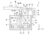
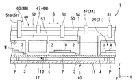
次に、本発明の実施形態を図面に基づいて説明する。図1はパレット搬送装置の斜視図である。また、図2は図1のA−A線に沿う断面図であり、図3は図1のB−B線に沿う断面図である。
図1〜3に示すように、パレット搬送装置1(以下、搬送装置1という)は、例えば電池等(ワークW)を製造する際に、液中での処理、加工を順次施すために用いるものであって、液体が貯留された搬送槽10を備えている。搬送槽10は、上部開口部を有する箱型形状のものであり、開口部内には底壁11と平行に配置され、パレットPが搬送される搬送レール12を備えている。搬送レール12は、底壁11からZ方向に立設された支柱19に支持されており、長手方向(X方向)に沿って形成され互いに平行な往路レーン20及び復路レーン21と、短手方向(Y方向)に沿って形成され、各レーン20,21の端部同士を連結する折り返しレーン24,25とで形成された循環路となっている。
(Pallet conveyor)
Next, embodiments of the present invention will be described with reference to the drawings. FIG. 1 is a perspective view of a pallet conveying device. 2 is a cross-sectional view taken along line AA in FIG. 1, and FIG. 3 is a cross-sectional view taken along line BB in FIG.
As shown in FIGS. 1 to 3, the pallet transfer device 1 (hereinafter referred to as the transfer device 1) is used to sequentially perform processing and processing in liquid when manufacturing a battery or the like (work W), for example. And the
なお、本実施形態のパレットPは、金属等からなる平板状の部材であり、その上面にワークWをセットできるようになっている。また、パレットPの上面における両端部には、パレットPの厚さ方向に沿って一対の位置決め穴2が形成されている。位置決め穴2は、後述する位置決め機構16に嵌合される穴であり、厚さ方向(Z方向)に沿って内径が漸次縮小するようなテーパ形状に形成されている。そして、往路レーン20及び復路レーン21上には、上述したパレットPがその長さ方向と搬送方向とを一致させた状態で、所定間隔毎に浸漬配置されている(図3参照)。
In addition, the pallet P of this embodiment is a flat plate member made of metal or the like, and the work W can be set on the upper surface thereof. In addition, a pair of
そして、搬送槽10における往路レーン20側の側壁13には、往路レーン20を搬送されるワークWに対して処理、加工を施すための複数の加工装置(加工ステージ)15が、搬送方向(X方向)に沿って所定間隔毎に設置されている。また、各加工装置15に隣接して一対の位置決め機構16が配置されている。この位置決め機構16は、搬送槽10の側壁13からY方向に沿って延出し、搬送槽10を臨むように設けられたベース部17と、このベース部17の先端に圧入された保持部18とで構成されている。なお、ベース部17と保持部18は、モーターやシリンダ、ボールネジ等の図示しない駆動手段により一体的に上下動可能(Z方向)に駆動される(図2中矢印U参照)。保持部18は、金属等からなる円柱形状のものであり、その下端部は下端に向かうにつれ外径が縮小するテーパ状に形成されている。この場合、パレットPが各加工装置15の加工ポジションまで搬送された際に、保持部18が下降してパレットPの位置決め穴2内に嵌合するようになっている。これにより、加工時のパレットPを位置決め固定することができるため、ワークWに対して高精度な加工を施すことができる。なお、ベース部17と保持部18は一体化され、位置決め時のみ保持部18が液中に浸漬されるようになっている。
A plurality of processing devices (processing stages) 15 for processing and processing the workpiece W transported in the
また、図1に示すように、搬送槽10における往路レーン20の上流端には、ワークWをパレットPにセットするためのワークセット部31が設けられる一方、往路レーン20の下流端には、加工されたワークWが取り出されるワーク取り出し部32が設けられている。なお、復路レーン21の上流側には、往路レーン20で加工されたワークWのうち、不良品と判断されたワークWを回収するためのワーク回収部(不図示)も備えている。
Further, as shown in FIG. 1, a
ここで、図1〜3に示すように、搬送装置1は、搬送レール12に沿ってパレットPを搬送するため搬送アーム42と、搬送アーム42を駆動する搬送機構40を備えている。搬送機構40は、両レーン20,21の搬送方向(X方向)に沿って搬送アーム42を往復移動させる送り機構43と、搬送方向に直交する方向(Y方向)に沿って搬送アーム42を旋回させる旋回機構44とを備えている。
1 to 3, the
送り機構43は、搬送槽10に平行に固定されたベッド45に対してスライド可能に支持されたテーブル41を備えている。このテーブル41は、X方向に沿って配置されており、テーブル41の上面には複数の腕部47が片持ち状に支持されている。腕部47は、一端側がテーブル41の上面に固定される一方、他端側が搬送槽10の復路レーン21側の側壁14から搬送槽10を臨むように延出しており、他端側の先端が両レーン20,21間の上方に配置されている。また、各腕部47は、X方向に沿って並んで設置されている。
各腕部47の先端には搬送方向(X方向)に沿って貫通孔48が形成され、各貫通孔48内には軸受け(不図示)を介してシャフト50が回転可能に支持されている。すなわち、シャフト50は、両レーン20,21間の上方で、両レーン20,21と平行に配置されている。そして、シャフト50には、クランプ部材51を介して複数の搬送アーム42が、X方向に沿って取り付けられている。
The
A through
各搬送アーム42は、金属等の平板状の部材からなりシャフト50のX方向と平行に延出する基部52と、この基部52から下方(Z方向)に向けて延出する複数のアーム部53と、基部52の両端部からそれぞれ下方に向けて延出するエンド部54とで構成されている。
アーム部53は、基部52に一体形成されるとともに、中央部に開口部を有する矩形枠型のものであり、基部52のX方向に沿って形成されている。したがって、各搬送アーム42は、アーム部53とエンド部54とがX方向に沿って櫛歯状に配置されている。この場合、アーム部53とエンド部54との距離は、パレットPの搬送方向(X方向)に沿う長さよりも長く設定されており、これらアーム部53とエンド部54との間にパレットPが挟み込まれるようになっている。なお、本実施形態では、シャフト50に複数の搬送アーム42を設けることで、各搬送アーム42の長さの和が両レーン20,21長さに相当するように構成しているが、一枚の搬送アームを両レーン20,21の長さと同等に形成してもよい。
Each
The
ところで、上述したテーブル41は、ベッド45のX方向に沿って形成されたスライドレール45a上に、X方向に沿ってスライド可能に支持されている。そして、テーブル41には、送り機構43をX方向に沿って往復移動可能とする駆動手段46が連結されている。この駆動手段46は、油圧または空気圧制御により作動するシリンダであり、一端側のシリンダ本体がベッド45に、他端側のシリンダロッドがテーブル41に連結されている。すなわち、シリンダロッドが伸長または縮退することで、テーブル41が所定ストローク毎に往復移動するように構成されている(図1中矢印S参照)。なお、所定ストロークとは、シリンダロッドの縮退端から伸長端までの長さである。また、テーブル41におけるシリンダロッドの伸長端側には、シリンダロッドの伸長駆動を減衰させるショックアブソーバー(不図示)や、シリンダロッドが、正常に伸長または縮退したか否かを検出するためのセンサー(不図示)が設けられている。なお、これらテーブル41、ベッド45及び駆動手段46等により搬送アーム42の送り機構43が構成されている。
By the way, the table 41 described above is supported on a
テーブル41の上面には、搬送アーム42をシャフト50の軸回りに旋回させる旋回機構44が設置されている。旋回機構44は、搬送槽10を臨むようにY方向に沿って延出する支持腕部60と、テーブル41の上面に設置され、支持腕部60をY方向に沿ってスライド可能とする駆動手段61とで構成されている。支持腕部60は、一端が駆動手段61に連結される一方、他端が複数のクランプ部材51のうち一のクランプ部材51a(図2参照)の上端側に回動可能に連結されている。すなわち、一のクランプ部材51aには、シャフト50を間に挟んで下端側に搬送アーム42、上端に支持腕部60が連結されている。旋回機構44の駆動手段61は、送り機構43の駆動手段46と同様に油圧または空気圧制御により作動するシリンダであり、駆動手段61のシリンダロッドが伸長または縮退することで、支持腕部60がY方向に沿って往復移動するようになっている。そして、支持腕部60が往復移動(図2中矢印T参照)することで、シャフト50の軸回りに搬送アーム42が旋回するように構成されている。
On the upper surface of the table 41, a
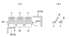
また、搬送槽10の復路レーン21の下流端には、復路レーン21の下流端まで搬送されたパレットPを往路レーン20の上流端に送り出す第1受け渡し機構65が設けられている。第1受け渡し機構65は、シリンダやモーター、ボールネジ等の駆動手段(不図示)を含み、スライド機構を有するガイド付シリンダ66と、ガイド付シリンダ66にスライド可能に支持された受け渡しアーム67と、受け渡しアーム67の先端に設けられ、パレットPを往路レーン20に向けて送り出すアーム部68とで構成されている。具体的に、受け渡しアーム67は、搬送槽10の側壁14から搬送槽10を臨むようにY方向に沿って延出している。また、アーム部68は、側壁14に沿って搬送アーム42の先端から搬送槽10内(下方)に向かって延出し、その先端が液中に浸漬してパレットPのY方向における側面に当接可能な位置まで延出している。
Further, a
一方、搬送槽10の往路レーン20の下流端には、往路レーン20の下流端まで搬送されたパレットPを復路レーン21の上流端に送り込む第2受け渡し機構70が設けられている。第2受け渡し機構70は、上述した第1受け渡し機構65と略同一の構成からなり、シリンダ等の駆動手段(不図示)を含むガイド付シリンダ71とガイド付シリンダ71にスライド可能に支持された受け渡しアーム72と、受け渡しアーム72の先端に設けられ、パレットPを復路レーン21に向けて送り込むアーム部73とで構成されている。具体的に、受け渡しアーム72は、搬送槽10の側壁14からY方向に沿って側壁13近傍まで延出している。また、アーム部73は、側壁13に沿って受け渡しアーム72の先端から搬送槽10内(下方)に向かって延出し、その先端が液中に浸漬してパレットPのY方向における側面に当接可能な位置まで延出している。
On the other hand, a
このように、上述した搬送機構40は、搬送アーム42に連結されたシャフト50が腕部47の軸受けを介して旋回可能に構成されるとともに、ベッド45に対して往復移動可能とされている。すなわち、腕部47の軸受けやシャフト50等が旋回機構44の動作支持部(旋回部)となっており、またベッド45やテーブル41等が送り機構43の動作支持部(スライド部)となっている。本実施形態の搬送機構40では、これら旋回部やスライド部等の動作支持部が、搬送槽10外の上方または側方に配置されており、液体には浸漬されていない。
さらに、受け渡し機構65,70においては、ガイド付シリンダ66,71や受け渡しアーム67,72が動作支持部(スライド部)となっており、これら動作支持部も搬送槽10の側方や上方に配置され、液体には浸漬されていない。
すなわち、本実施形態の搬送装置1では、液体に浸漬されている部材は、一体形成された部材(例えば、搬送アーム42、アーム部68,73)や搬送槽10に固定された部材(例えば、搬送レール12)である。これに対して、各動作支持部(例えば、旋回部やスライド部)は液中に浸漬されておらず、全て搬送槽10外にレイアウトされている。
As described above, the
Further, in the
That is, in the
さらに、本実施形態の搬送装置1では、搬送槽10外における両レーン20,21のうち往路レーン20側の側方に、ワークWに対して加工を施すための加工装置15が設置される一方、復路レーン21側の側方に、上述した各機構(搬送機構40、旋回機構44、受け渡し機構65,70等)の駆動手段(例えば、駆動手段46,61)が設けられている。このように、各機構の駆動手段を一端側にまとめて配置することで、装置のコンパクト化を図るとともに、各機構のメンテナンスを復路レーン21側で一括して行えることができるので、メンテナンス性の向上を図ることができる。また、上述した動作支持部と同様に、これら各機構の駆動手段も搬送槽10の液中には浸漬されておらず、全て搬送槽10外にレイアウトされている。
Furthermore, in the
(搬送方法)
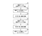
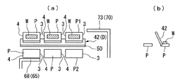
次に、上述した搬送装置1を用いた搬送方法について説明する。図4は、本実施形態の搬送方法を説明するためのフローチャートである。また、図5〜9は搬送方法を説明するための説明図であり、(a)は搬送装置の平面図、(b)は断面図を示している。なお、図5〜9では説明を分かり易くするため、各部材を簡略化して図示している。
まず図2,5に示すように、初期状態では、搬送レール12上に所定間隔毎に複数のパレットPが浸漬配置されているとともに、先頭パレットP1と最後方パレットP2との間にはパレットPの2枚分のスペースが設定されている。なお、以下の説明において、先頭パレットP1と最後方パレットP2とパレットPとを区別する必要がない場合は、まとめてパレットPとする。
(Conveying method)
Next, a conveyance method using the above-described
First, as shown in FIGS. 2 and 5, in the initial state, a plurality of pallets P are soaked at predetermined intervals on the
そして、図2,4,5に示すように、パレットPを搬送する場合には、まず搬送アーム42を往路ポジション(図2中D参照)に旋回させる(S1)。具体的には、旋回機構44の駆動手段61を縮退駆動させる。すると、支持腕部60が復路レーン21側に向かってY方向に沿ってスライドし、このスライド動作に伴ってクランプ部材51aがシャフト50の軸回りに回動する。これにより、クランプ部材51aの上端側が、復路レーン21側に傾き、搬送アーム42がシャフト50の軸回りに旋回する(図2中反時計回り)。そして、搬送アーム42のアーム部53及びエンド部54の先端が往路レーン20上に配置され、アーム部53とエンド部54とが往路レーン20上に配置された各パレットP間に入り込む。これにより、アーム部53とエンド部54との間で、パレットPの搬送方向(X方向)に沿う側面3,4を挟み込むようになる(往路ポジションD)。
As shown in FIGS. 2, 4, and 5, when the pallet P is transported, the
次に、図2,4,6に示すように、搬送アーム42を往路ポジションDに設定した状態で、搬送アーム42を往路レーン20の搬送方向(X方向)に沿ってスライドさせる(S2)。具体的には、送り機構43の駆動手段46を伸長駆動させる。すると、テーブル41が、スライドレール45a上を往路レーン20の搬送方向に沿ってスライドする。この時、搬送アーム42は往路ポジションDにあるので、搬送アーム42が往路レーン20の下流側に向かってスライドすると、アーム部53またはエンド部54がパレットPの搬送方向における上流側の側面4に当接する。そして、この側面4に当接した状態で搬送アーム42がスライドすることで、パレットPがアーム部53またはエンド部54によって往路レーン20の下流側へ押し出される。よって、往路レーン20上に配列された各パレットPを、一斉に下流側へ所定ストローク搬送することができる。
Next, as shown in FIGS. 2, 4, and 6, the
この場合、各パレットPは、一段下流側の加工装置15の加工ポジションまで搬送される。すると、まず位置決め機構16の保持部18が下降し、保持部18がパレットPの位置決め穴2に嵌合する。これにより、パレットPの位置決めが完了する。その後、パレットPを位置決めした状態で、各加工装置15によってワークWに対して所定の処理、加工が施される。
また、この時点で先頭パレットP1は、往路レーン20の下流端まで搬送される。往路レーン20の下流端まで搬送されたワークWのうち、良品のワークWはワーク取り出し部32にて搬送槽10から取り出され、その後の後処理装置(不図示)等へ搬送される。一方、不良品のワークWは、ワーク取り出し部32では取り出されず、パレットPにセットされた状態で後段へと搬送されるようになっている。
In this case, each pallet P is conveyed to the processing position of the
At this time, the leading pallet P1 is conveyed to the downstream end of the
そして、図4,7に示すように、往路レーン20の各パレットPが下流側へ移動したら、復路レーン21の下流端にあるパレットPを往路レーン20の上流端、すなわちワークセット部31へと搬送する(S3)。具体的には、第1受け渡し機構65の駆動手段を駆動させ、受け渡しアーム67を往路レーン20側に向けて伸長させる。受け渡しアーム67がスライドすると、アーム部68がパレットPの復路レーン21側の側面に当接した状態で、パレットPを往路レーン20に向けて押し出す。押し出されたパレットPは、折り返しレーン24を通って往路レーン20のワークセット部31の下方まで搬送される。パレットPがワークセット部31の下方まで搬送されると、パレットPの上面にワークWがセットされる。
4 and 7, when each pallet P in the
続いて、図2,4,7に示すように、ワークセット部31でのワークWのセットや加工装置15でのワークWに対する処理、加工が終了したら、復路レーン21のパレットPを下流側に搬送する。そのため、まず搬送アーム42を往路ポジションDから復路ポジションEへと旋回させる(S4)。具体的には、旋回機構44の駆動手段61を伸長駆動させ、復路レーン21側に向かってY方向に沿って支持腕部60をスライドさせる。すると、このスライド動作に伴ってクランプ部材51aがシャフト50の軸回りに回動する。これにより、クランプ部材51aの上端側が、往路レーン20側に傾き、搬送アーム42がシャフト50の軸回りに旋回する(図2中時計回り)。そして、搬送アーム42のアーム部53及びエンド部54の先端が復路レーン21上に配置され、アーム部53とエンド部54とが復路レーン21上に配置された各パレットP間に入り込む。これにより、アーム部53とエンド部54との間で、パレットPの搬送方向(X方向)に沿う側面3,4を挟み込むようになる(復路ポジションE)。
Subsequently, as shown in FIGS. 2, 4, and 7, when the setting of the workpiece W in the
その後、図8に示すように、搬送アーム42を復路ポジションEへ旋回させたら、第1受け渡し機構65の駆動手段を駆動させ、受け渡しアーム67を元の位置に戻すとともに、第2受け渡し機構70によって往路レーン20の下流端にあるパレットPを復路レーン21の上流端へと搬送する(S5)。具体的には、第2受け渡し機構70の駆動手段を駆動させ、受け渡しアーム72を復路レーン21に向けてスライドさせる。受け渡しアーム72がスライドすると、アーム部73がパレットPの往路レーン20側の側面に当接した状態で、パレットPを復路レーン21に向けて引き込む。引き込まれたパレットPは、折り返しレーン25を通って復路レーン21の上流端まで搬送される。なお、パレットPを復路レーン21の上流端まで搬送した時点で、ワーク取り出し部32で取り出されなかった不良品のワークWは、ワーク回収部で回収される。したがって、復路レーン21では、ワークWがセットされていない空のパレットPが搬送されることになる。
After that, as shown in FIG. 8, when the
次に、図2,4,9に示すように、搬送アーム42を復路ポジションEに設定した状態で、搬送アーム42を復路レーン21の搬送方向に沿ってスライドさせる(S6)。具体的には、送り機構43を縮退駆動させる。すると、テーブル41が、スライドレール上を復路レーン21の下流側へスライドする。この時、搬送アーム42は復路ポジションEにあるので、搬送アーム42が復路レーン21の下流側に向かってスライドすると、アーム部53またはエンド部54がパレットPの搬送方向における上流側の側面4に当接する。そして、この側面に当接した状態で搬送アーム42がスライドすることで、パレットPがアーム部53またはエンド部54によって復路レーン21の下流側へ押し出される。よって、復路レーン21上に配列されたパレットPを、一斉に復路レーン21の下流側へ所定ストローク搬送することができる。
そして、上述したステップS1〜S6を繰り返すことで、パレットPが搬送槽10の搬送レール12上を循環するように搬送される。
Next, as shown in FIGS. 2, 4, and 9, the
And the pallet P is conveyed so that it may circulate on the
このように、本実施形態では、往路ポジションDと復路ポジションEとの間で搬送アーム42を旋回させる旋回機構44と、搬送方向(X方向)に沿って搬送アーム42を往復移動させる送り機構43とを備える構成とした。
この構成によれば、往路ポジションDに搬送アーム42を旋回させた状態で、搬送アーム42を往路レーン20の搬送方向(X方向)に移動させることで、往路レーン20のパレットPを往路レーン20の下流側へ搬送することができる。一方、復路ポジションEに搬送アーム42を旋回させたで、搬送アーム42を復路レーン21の搬送方向(X方向)に移動させることで、復路レーン21のパレットPを復路レーン21の下流側へ搬送することができる。
すなわち、搬送方向に沿って往復移動する搬送アーム42を、往路ポジションDまたは復路ポジションEへ交互に移動させることで、一つの搬送アーム42によって往路レーン20及び復路レーン21のパレットPを、各レーン20,21の下流側へ交互に搬送することができる。これにより、従来のように往路レーン20及び復路レーン21との両レーン20,21に、搬送アーム等の移動機構をそれぞれ設ける必要がないので、装置の低コスト化及び簡素化を図ることができる。
As described above, in this embodiment, the
According to this configuration, the pallet P of the
That is, by alternately moving the
さらに、折り返しレーン24,25に、往路レーン20の下流端まで搬送されたパレットPを復路レーン21へ、また復路レーン21の下流端まで搬送されたパレットPを再び往路レーン20へ搬送する受け渡し機構65,70を設けることで、構成を複雑化させずに、循環路上でパレットPをスムーズに循環させることができる。
さらに、本実施形態では、往路ポジションDと復路ポジションEとの間で、搬送アーム42がシャフト50の軸回りに旋回可能とされているので、例えば搬送アーム42全体を往路ポジションDと復路ポジションEとの間でスライドさせる場合等に比べて、搬送アーム42の可動範囲が小さい。そのため、レイアウト性を向上させることができ、装置の大型化を防ぐことができる。また、搬送アーム42をスライドさせるレール等を設ける必要もなく、1つの旋回機構44により搬送アーム42をシャフト50の軸回りに容易に旋回することができるので、装置のさらなる簡素化も図ることができる。
さらに、旋回機構44がクランプ部材51aにおけるシャフト50よりも上方に設置されているため、シャフト50と両レーン20,21との間に旋回機構44を配置することがなくなり、旋回機構44が搬送槽10等に干渉したりする虞がない。したがって、旋回機構44のレイアウト性を向上させることができる。
Further, the pallet P transported to the
Furthermore, in this embodiment, since the
Furthermore, since the
ここで、本実施形態の搬送装置1は、往路レーン20の上流端にワークセット部31が設置されているので、搬送レール12を循環してきた空のパレットPに対してスムーズにワークWをセットしていくことができる。一方、往路レーン20の下流端にワーク取り出し部32が設置されているので、往路レーン20上で加工、処理が施されたワークWを取り出して、その後の後処理装置へとスムーズに搬送することができる。したがって、作業効率を向上させることが可能である。
さらに、往路レーン20の搬送方向に沿って複数の加工装置15が設置され、これら加工装置15に隣接して位置決め機構16が設けられているので、加工ポジションにあるパレットP(ワークW)と加工装置15との相対位置を正確に位置合わせすることができる。これにより、ワークWに対して高精度な加工を行なうことができる。
したがって、搬送装置1内で製造される製品の歩留まりを向上させることができるとともに、信頼性の高い製品を提供することができる。
Here, since the work set
Further, since a plurality of
Therefore, it is possible to improve the yield of products manufactured in the
以上、本発明の実施形態について図面を参照して詳述したが、具体的な構成はこれら実施形態に限られるものではなく、本発明の要旨を逸脱しない範囲の設計変更等も含まれる。 As mentioned above, although embodiment of this invention was explained in full detail with reference to drawings, the concrete structure is not restricted to these embodiment, The design change etc. of the range which does not deviate from the summary of this invention are included.
例えば、上述した実施形態では、送り機構43及び旋回機構44にシリンダを採用する場合について説明したが、シリンダに限らずボールネジやモーター等を採用することが可能である。
また、上述した実施形態では、液中でパレットPを搬送する場合について説明したが、液中に限らず、通常の大気中でパレットPを搬送する際についても搬送装置1を採用することができる。
For example, in the above-described embodiment, the case where a cylinder is employed for the
Moreover, although embodiment mentioned above demonstrated the case where the pallet P was conveyed in a liquid, the conveying
また、往路ポジションDと復路ポジションEとの間で搬送アーム42を旋回させる場合について説明したが、これに限らず搬送アーム42をスライドさせても構わない。
さらに、搬送装置1で搬送するパレットPの個数は適宜変更が可能である。
Moreover, although the case where the
Furthermore, the number of pallets P conveyed by the conveying
1…搬送装置 12…搬送レール(搬送路) 15…加工装置 16…位置決め機構 20…往路レーン 21…復路レーン 24,25…折り返しレーン 31…ワークセット部 32…ワーク取り出し部 42…搬送アーム 43…送り機構 44…旋回機構(移動機構) 50…シャフト 67,72…受け渡し機構 P…パレット W…ワーク
DESCRIPTION OF
Claims (8)
前記搬送路は、互いに平行に配置された往路レーン及び復路レーンを有し、
前記パレットの上流側の側面に当接した状態で、前記両レーンの下流側へ向かって前記パレットを搬送する搬送アームと、
前記搬送方向に沿って前記搬送アームを所定ストロークで往復移動可能とする送り機構と、
前記往路レーンと前記復路レーンとの間で、前記搬送アームを往復移動可能とする移動機構とを備えていることを特徴とするパレットの搬送装置。 In a pallet transport device that transports a pallet on which a workpiece can be set along the transport path,
The transport path has an outward lane and a return lane arranged in parallel to each other,
A transport arm that transports the pallet toward the downstream side of the two lanes in a state of contacting the upstream side surface of the pallet;
A feed mechanism capable of reciprocating the transport arm with a predetermined stroke along the transport direction;
A pallet transport apparatus comprising: a moving mechanism that enables the transport arm to reciprocate between the forward lane and the return lane.
前記往路レーンの下流端と前記復路レーンの上流端とを連結する第2折り返しレーンとを有し、
前記第1折り返しレーンを通って前記パレットを搬送する第1受け渡し機構と、前記第2折り返しレーンを通って前記パレットを搬送する第2受け渡し機構とを備えていることを特徴とする請求項1記載のパレットの搬送装置。 The transport path includes a first turn-back lane connecting a downstream end of the return lane and an upstream end of the forward lane;
A second folded lane connecting the downstream end of the forward lane and the upstream end of the return lane;
The first delivery mechanism for transporting the pallet through the first return lane and the second delivery mechanism for transporting the pallet through the second return lane. Pallet transport device.
前記移動機構は、前記往路レーンと前記復路レーンとの間で、前記搬送アームを前記シャフトの軸回りに旋回させることを特徴とする請求項1または請求項2記載のパレットの搬送装置。 The transfer arm is supported so as to be able to turn around a shaft disposed in parallel with the lanes above the lanes,
3. The pallet transport apparatus according to claim 1, wherein the moving mechanism turns the transport arm around the axis of the shaft between the forward lane and the return lane. 4.
下流端に、前記加工装置で加工された前記ワークを前記パレットから取り出すワーク取り出し部が設置されていることを特徴とする請求項1ないし請求項5の何れか1項に記載のパレットの搬送装置。 In the forward lane, a work set unit for setting the work before processing on the pallet is installed at the upstream end thereof,
The pallet transport device according to any one of claims 1 to 5, wherein a workpiece take-out unit for removing the workpiece processed by the processing device from the pallet is installed at a downstream end. .
前記移動機構を駆動させ、前記往路レーン側に向けて前記搬送アームを移動させるステップと、
前記送り機構を駆動させ、前記搬送アームを前記往路レーンの下流側に移動させるステップと、
前記移動機構を駆動させ、前記復路レーン側に向けて前記搬送アームを移動させるとともに、前記第1受け渡し機構を駆動させ、前記復路レーンの下流端にある前記パレットを前記往路レーンの上流端へ受け渡すステップと、
前記第2受け渡し機構を駆動させ、前記往路レーンの下流端にある前記パレットを前記復路レーンの上流端へ受け渡すステップと、
前記送り機構を駆動させ、前記搬送アームを前記復路レーンの下流側に移動させるステップとを有することを特徴とするパレットの搬送方法。 A method for transporting the pallet using the transport device according to any one of claims 1 to 7,
Driving the moving mechanism to move the transfer arm toward the forward lane side; and
Driving the feed mechanism and moving the transfer arm downstream of the forward lane;
The moving mechanism is driven to move the transfer arm toward the return lane, and the first delivery mechanism is driven to receive the pallet at the downstream end of the return lane at the upstream end of the forward lane. Passing step,
Driving the second delivery mechanism to deliver the pallet at the downstream end of the forward lane to the upstream end of the return lane;
Driving the feed mechanism and moving the transport arm to the downstream side of the return lane.
Priority Applications (1)
| Application Number | Priority Date | Filing Date | Title |
|---|---|---|---|
| JP2009030990A JP2010184792A (en) | 2009-02-13 | 2009-02-13 | Pallet carrying device and carrying method |
Applications Claiming Priority (1)
| Application Number | Priority Date | Filing Date | Title |
|---|---|---|---|
| JP2009030990A JP2010184792A (en) | 2009-02-13 | 2009-02-13 | Pallet carrying device and carrying method |
Publications (1)
| Publication Number | Publication Date |
|---|---|
| JP2010184792A true JP2010184792A (en) | 2010-08-26 |
Family
ID=42765694
Family Applications (1)
| Application Number | Title | Priority Date | Filing Date |
|---|---|---|---|
| JP2009030990A Pending JP2010184792A (en) | 2009-02-13 | 2009-02-13 | Pallet carrying device and carrying method |
Country Status (1)
| Country | Link |
|---|---|
| JP (1) | JP2010184792A (en) |
Cited By (2)
| Publication number | Priority date | Publication date | Assignee | Title |
|---|---|---|---|---|
| JP2012176457A (en) * | 2011-02-25 | 2012-09-13 | Yaskawa Electric Corp | Work system |
| CN113911746A (en) * | 2021-11-22 | 2022-01-11 | 广州城市理工学院 | Stacking device |
-
2009
- 2009-02-13 JP JP2009030990A patent/JP2010184792A/en active Pending
Cited By (4)
| Publication number | Priority date | Publication date | Assignee | Title |
|---|---|---|---|---|
| JP2012176457A (en) * | 2011-02-25 | 2012-09-13 | Yaskawa Electric Corp | Work system |
| US8887893B2 (en) | 2011-02-25 | 2014-11-18 | Kabushiki Kaisha Yaskawa Denki | Work system |
| CN113911746A (en) * | 2021-11-22 | 2022-01-11 | 广州城市理工学院 | Stacking device |
| CN113911746B (en) * | 2021-11-22 | 2023-09-22 | 广州城市理工学院 | Superposition device |
Similar Documents
| Publication | Publication Date | Title |
|---|---|---|
| KR101763268B1 (en) | Transfer system | |
| CN102189274B (en) | For loading the charger for carrying out the bar processed in lathe | |
| KR102013447B1 (en) | Apparatus for ejecting and transferring workpiece | |
| JP4935442B2 (en) | Plate material unloading apparatus and plate material unloading method | |
| CN205600088U (en) | Automatic tin soldering machine | |
| CN105817729A (en) | Tin soldering method and automatic tin soldering machine | |
| CN206898241U (en) | A kind of press machine loading and unloading manipulator | |
| KR20060071591A (en) | Aluminum tube bunch drawing machine | |
| WO2016051657A1 (en) | Workpiece loading method | |
| JP2010184792A (en) | Pallet carrying device and carrying method | |
| JP2007160375A (en) | Workpiece transporting apparatus for laser beam machine | |
| JP2010005628A (en) | Multistage pressing apparatus | |
| JP3724900B2 (en) | Cylinder sleeve transfer device | |
| JP2010184798A (en) | Pallet carrying device and carrying method | |
| JP5793882B2 (en) | Article supply equipment | |
| JP2016098099A (en) | Workpiece conveyance device and workpiece conveyance method | |
| CN210709515U (en) | Assembly line | |
| CN210418292U (en) | Cartridge delivery device | |
| JP5155694B2 (en) | Pallet transport device | |
| JP5058021B2 (en) | Pallet transport device | |
| JP2009068975A (en) | Environment testing apparatus and work feeding method of environment testing apparatus | |
| JP4715266B2 (en) | Panel conveyor | |
| JP7400427B2 (en) | Workpiece transfer method and workpiece transfer device | |
| KR101479563B1 (en) | An automatic pipe supply appartus | |
| CN211544060U (en) | Plate-shaped object positioning device |