JP2010143674A - Semiconductor ingot reversing device - Google Patents

Semiconductor ingot reversing device Download PDF

Info

Publication number
JP2010143674A
JP2010143674A JP2008320664A JP2008320664A JP2010143674A JP 2010143674 A JP2010143674 A JP 2010143674A JP 2008320664 A JP2008320664 A JP 2008320664A JP 2008320664 A JP2008320664 A JP 2008320664A JP 2010143674 A JP2010143674 A JP 2010143674A
Authority
JP
Japan
Prior art keywords
ingot
unit
holding
arm
semiconductor ingot
Prior art date
Legal status (The legal status is an assumption and is not a legal conclusion. Google has not performed a legal analysis and makes no representation as to the accuracy of the status listed.)
Granted
Application number
JP2008320664A
Other languages
Japanese (ja)
Other versions
JP5417833B2 (en
Inventor
Shunichi Imao
俊一 今尾
Current Assignee (The listed assignees may be inaccurate. Google has not performed a legal analysis and makes no representation or warranty as to the accuracy of the list.)
Sumco Corp
Original Assignee
Sumco Corp
Priority date (The priority date is an assumption and is not a legal conclusion. Google has not performed a legal analysis and makes no representation as to the accuracy of the date listed.)
Filing date
Publication date
Application filed by Sumco Corp filed Critical Sumco Corp
Priority to JP2008320664A priority Critical patent/JP5417833B2/en
Publication of JP2010143674A publication Critical patent/JP2010143674A/en
Application granted granted Critical
Publication of JP5417833B2 publication Critical patent/JP5417833B2/en
Expired - Fee Related legal-status Critical Current
Anticipated expiration legal-status Critical

Links

Images

Landscapes

  • Attitude Control For Articles On Conveyors (AREA)

Abstract

【課題】半導体インゴットを傷つけることなく、容易に反転させることが可能な半導体インゴット反転装置を提供すること。
【解決手段】半導体インゴット反転装置4aは、略円柱状の半導体インゴット11を直接的に又は間接的に保持可能なアーム部51と、アーム部51を第1の位置から第2の位置に回動させる回動駆動部52と、を有する回動アーム部50と、回動アーム部50により第2の位置に移動された半導体インゴット11を直接的に又は間接的に保持可能な第1保持部61と、第1保持部61を上下方向に昇降させる第1駆動部62と、を有する第1昇降部60と、を備える。
【選択図】図5
A semiconductor ingot reversing device capable of easily reversing without damaging the semiconductor ingot is provided.
A semiconductor ingot reversing device 4a includes an arm 51 capable of directly or indirectly holding a substantially cylindrical semiconductor ingot 11, and the arm 51 is rotated from a first position to a second position. A rotation arm unit 50 having a rotation drive unit 52 to be moved, and a first holding unit 61 capable of directly or indirectly holding the semiconductor ingot 11 moved to the second position by the rotation arm unit 50. And a first elevating unit 60 having a first drive unit 62 that elevates and lowers the first holding unit 61 in the vertical direction.
[Selection] Figure 5

Description

本発明は、半導体インゴットの反転装置に関する。   The present invention relates to a semiconductor ingot reversing device.

従来より、シリコンウェーハ等の半導体ウェーハは、シリコン等の原料により略円柱状に形成された半導体インゴットをスライス処理することにより製造される。そして、この半導体インゴットのスライス処理は、インゴットの大径化に伴い、内刃スライス装置によるスライス処理から、ワイヤソー装置による同時スライス処理によって製造する方法に移行している。   Conventionally, a semiconductor wafer such as a silicon wafer is manufactured by slicing a semiconductor ingot formed in a substantially cylindrical shape with a raw material such as silicon. Then, the slicing process of the semiconductor ingot is shifted from the slicing process by the inner blade slicing apparatus to the method of manufacturing by the simultaneous slicing process by the wire saw apparatus as the diameter of the ingot is increased.

ワイヤソー装置は、複数のローラに螺旋状に一定の間隔で巻き回されて走行されるワイヤ列からなるスライス経路を有している。ワイヤソー装置は、半導体インゴットの外周面がこのスライス経路と対向するように半導体インゴットを配置し、この状態で半導体インゴットを下降させることにより、半導体インゴットを一定の厚さにスライスするように構成されている(例えば、特許文献1参照)。   The wire saw device has a slice path composed of a wire train that is wound around a plurality of rollers in a spiral manner at a predetermined interval. The wire saw device is configured to slice the semiconductor ingot to a certain thickness by arranging the semiconductor ingot so that the outer peripheral surface of the semiconductor ingot faces the slice path and lowering the semiconductor ingot in this state. (For example, refer to Patent Document 1).

ここで、ワイヤソー装置によりスライスされる半導体インゴットは、上述のように、ワイヤソー装置の上方から、外周面をスライス経路と対向させた状態でスライス経路に向かって下降される。そのため、半導体インゴットの外周面には、半導体インゴットをワイヤソー装置の上方で保持するために固着された固着部材が設けられる。   Here, as described above, the semiconductor ingot sliced by the wire saw device is lowered from above the wire saw device toward the slice path with the outer peripheral surface facing the slice path. Therefore, a fixing member fixed to hold the semiconductor ingot above the wire saw device is provided on the outer peripheral surface of the semiconductor ingot.

固着部材は、通常、接着剤により半導体インゴットに接着される。そして、固着部材は、半導体インゴットを固着部材の上にした状態で所定時間乾燥させることにより、半導体インゴットに固着される。つまり、ワイヤソー装置に供給される半導体インゴットは、下方側に固着部材が固着され、この状態でワイヤソー装置に供給されるまで保管される。そのため、半導体インゴットは、ワイヤソー装置によりスライスされる前に、固着部材が半導体インゴットの上方側にくるように反転させる必要がある。そして、従来は、この半導体インゴットの反転作業は、作業者による手作業により行われていた。
特開2008−254173号公報
The fixing member is usually bonded to the semiconductor ingot with an adhesive. The fixing member is fixed to the semiconductor ingot by drying for a predetermined time in a state where the semiconductor ingot is placed on the fixing member. In other words, the semiconductor ingot supplied to the wire saw device is stored until the fixing member is fixed to the lower side and is supplied to the wire saw device in this state. Therefore, before the semiconductor ingot is sliced by the wire saw device, it is necessary to invert the fixing member so that the fixing member comes above the semiconductor ingot. Conventionally, the reversing operation of the semiconductor ingot has been performed manually by an operator.
JP 2008-254173 A

しかしながら、昨今においては、半導体インゴットの大径化に伴い、作業者の手作業による反転作業が困難になっていた。特に、半導体インゴットは、脆く壊れやすいため、作業者による作業では、壊れるおそれがあった。   However, in recent years, with the increase in the diameter of the semiconductor ingot, it has become difficult for the operator to perform the reversing operation manually. In particular, the semiconductor ingot is fragile and fragile, and therefore, there is a possibility that the semiconductor ingot may be broken by work by an operator.

本発明は、容易に反転させることが可能な半導体インゴット反転装置を提供することを目的とする。   An object of the present invention is to provide a semiconductor ingot reversing device that can be easily reversed.

(1)本発明の半導体インゴット反転装置は、略円柱状の半導体インゴットを直接的に又は間接的に保持可能なアーム部と、前記アーム部を第1の位置から第2の位置に回動させる回動駆動部と、を有する回動アーム部と、前記回動アーム部により前記第2の位置に移動された前記半導体インゴットを直接的に又は間接的に保持可能な第1保持部と、前記第1保持部を上下方向に昇降させる第1駆動部と、を有する第1昇降部と、を備えることを特徴とする。   (1) A semiconductor ingot reversing device of the present invention comprises an arm part capable of directly or indirectly holding a substantially cylindrical semiconductor ingot, and the arm part is rotated from a first position to a second position. A rotation arm unit having a rotation drive unit; a first holding unit capable of directly or indirectly holding the semiconductor ingot moved to the second position by the rotation arm unit; A first elevating unit having a first drive unit that elevates and lowers the first holding unit in the vertical direction.

(2)また、前記回動駆動部は、前記アーム部を180度回動させることが好ましい。   (2) Moreover, it is preferable that the said rotation drive part rotates the said arm part 180 degree | times.

(3)また、本発明の半導体インゴット反転装置は、前記第1の位置に位置する前記半導体インゴットを直接的に又は間接的に保持可能な第2保持部と、前記第2保持部を上下方向に昇降させる第2駆動部と、を有する第2昇降部を更に備えることが好ましい。   (3) Moreover, the semiconductor ingot reversing device of the present invention includes a second holding part capable of directly or indirectly holding the semiconductor ingot positioned at the first position, and the second holding part in the vertical direction. It is preferable to further include a second elevating unit having a second drive unit that moves up and down.

(4)また、半導体インゴットの外周面の一部には、固着部材が固着され、前記第1保持部は、前記固着部材を介して前記半導体インゴットを間接的に保持することが好ましい。   (4) Preferably, a fixing member is fixed to a part of the outer peripheral surface of the semiconductor ingot, and the first holding portion indirectly holds the semiconductor ingot via the fixing member.

(5)また、前記アーム部は、前記半導体インゴットを保持した前記第1保持部が上昇した後、前記半導体インゴットを把持しない状態で前記第2の位置から回動駆動部により回動され、前記第1保持部は、前記アーム部が前記第2の位置から回動した後、前記第1駆動部により下降されることが好ましい。   (5) Further, the arm portion is rotated by the rotation driving unit from the second position without holding the semiconductor ingot after the first holding unit holding the semiconductor ingot is raised, The first holding unit is preferably lowered by the first driving unit after the arm unit is rotated from the second position.

本発明によれば、容易に反転させることが可能な半導体インゴット反転装置を提供することができる。   According to the present invention, it is possible to provide a semiconductor ingot reversing device that can be easily reversed.

以下、本発明を実施するための最良の形態について、図面を参照しながら説明する。
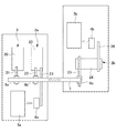
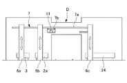
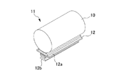
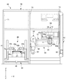
まず、図1から図3を参照して、本発明の実施形態に係る半導体インゴット反転装置としての第1反転装置4a及び第2反転装置4bを備えるインゴットスライスシステム1の概略構成について説明する。図1は、本実施形態に係るインゴット反転装置を備えるインゴットスライスシステムの概略構成を示す平面図である。図2は、図1に示すインゴットスライスシステムの概略構成を示す正面図である。図3は、本実施形態に係るインゴット反転装置により反転される第2インゴットを示す外観斜視図である。
The best mode for carrying out the present invention will be described below with reference to the drawings.
First, a schematic configuration of an ingot slice system 1 including a first inversion device 4a and a second inversion device 4b as semiconductor ingot inversion devices according to an embodiment of the present invention will be described with reference to FIGS. FIG. 1 is a plan view illustrating a schematic configuration of an ingot slicing system including an ingot inverting device according to the present embodiment. FIG. 2 is a front view showing a schematic configuration of the ingot slice system shown in FIG. FIG. 3 is an external perspective view showing the second ingot reversed by the ingot reversing device according to the present embodiment.

図1及び図2に示すように、インゴットスライスシステム1は、第1ストッカ2aと、第2ストッカ2bと、接着装置3と、第1反転装置4aと、第2反転装置4bと、第1スライス装置5aと、第2スライス装置5bと、第1リフタ6aと、第2リフタ6bと、第3リフタ6cと、インゴット搬送装置7と、を備えて構成されている。   As shown in FIGS. 1 and 2, the ingot slice system 1 includes a first stocker 2a, a second stocker 2b, an adhesive device 3, a first reversing device 4a, a second reversing device 4b, and a first slice. A device 5a, a second slicing device 5b, a first lifter 6a, a second lifter 6b, a third lifter 6c, and an ingot transfer device 7 are provided.

図3に示すように、第2インゴット11は、第1インゴット10と、インゴットヘッド12とを有して構成されている。第2インゴット11は、第1インゴット10にインゴットヘッド12を接着させることにより形成される。第1インゴット10は、シリコン原料により略円柱状に形成されている。第1インゴット10には、オリエンテーションフラット(図示せず)が設けられている。インゴットヘッド12は、当て板部12aと、ヘッド部12bと、を有して構成されている。当て板部12aは、矩形板状に形成されており、長手方向が第1インゴット10の軸方向と一致するように、第1インゴット10の外周面に接着されている。当て板部12aは、オリエンテーションフラットに沿った状態で接着されている。ヘッド部12bは、略直方体状に形成されている。ヘッド部21bは、長手方向が当て板部12aの長手方向と一致するように、当て板部12aの幅方向の略中央部に接着されている。   As shown in FIG. 3, the second ingot 11 includes a first ingot 10 and an ingot head 12. The second ingot 11 is formed by adhering the ingot head 12 to the first ingot 10. The first ingot 10 is formed in a substantially cylindrical shape from a silicon raw material. The first ingot 10 is provided with an orientation flat (not shown). The ingot head 12 includes a contact plate portion 12a and a head portion 12b. The contact plate portion 12 a is formed in a rectangular plate shape, and is bonded to the outer peripheral surface of the first ingot 10 so that the longitudinal direction coincides with the axial direction of the first ingot 10. The contact plate portion 12a is bonded in a state along the orientation flat. The head portion 12b is formed in a substantially rectangular parallelepiped shape. The head portion 21b is bonded to the substantially central portion in the width direction of the backing plate portion 12a so that the longitudinal direction coincides with the longitudinal direction of the backing plate portion 12a.

インゴット搬送装置7は、第1ストッカ2a、接着装置3、第1反転装置4a、第1スライス装置5a、第1リフタ6a及び第2リフタ6bと、第2ストッカ2b、第2反転装置4b、第2スライス装置5b及び第3リフタ6cとを連通させる搬送通路Dに配設されている。   The ingot transfer device 7 includes a first stocker 2a, a bonding device 3, a first reversing device 4a, a first slicing device 5a, a first lifter 6a and a second lifter 6b, a second stocker 2b, a second reversing device 4b, A two-slice device 5b and a third lifter 6c are disposed in a conveyance path D that allows communication.

第1ストッカ2aは、第1保管部20と、第1搬送コンベア22と、第2搬送コンベア23と、を有する。第1保管部20は、搬入された円柱状のインゴット(以下、「第1インゴット10」という)及び、接着装置3により固着部材としてのインゴットヘッド12が接着されたインゴット(以下、「第2インゴット11」という)を保管する。第1搬送コンベア22は、第1保管部20と第2リフタ6bとを接続する。第1搬送コンベア22は、第1保管部20に保管された第1インゴット10を第2リフタ6bに搬送する。また、第1搬送コンベア22は、接着装置3でインゴットヘッド12が接着された第2インゴット11を第1保管部20に搬送する。第2搬送コンベア23は、第1保管部20と第1反転装置4aとを接続する。第2搬送コンベア23は、第1保管部20に保管された第2インゴット11を第1反転装置4aに搬送する。   The first stocker 2 a includes a first storage unit 20, a first transport conveyor 22, and a second transport conveyor 23. The first storage unit 20 includes a columnar ingot (hereinafter referred to as “first ingot 10”) and an ingot (hereinafter referred to as “second ingot”) to which an ingot head 12 as a fixing member is bonded by the bonding device 3. 11 ”). The 1st conveyance conveyor 22 connects the 1st storage part 20 and the 2nd lifter 6b. The 1st conveyance conveyor 22 conveys the 1st ingot 10 stored in the 1st storage part 20 to the 2nd lifter 6b. In addition, the first transport conveyor 22 transports the second ingot 11 to which the ingot head 12 is bonded by the bonding apparatus 3 to the first storage unit 20. The 2nd conveyance conveyor 23 connects the 1st storage part 20 and the 1st inversion apparatus 4a. The second conveyor 23 conveys the second ingot 11 stored in the first storage unit 20 to the first reversing device 4a.

接着装置3は、接着装置本体30と、第3搬送コンベア31とを有する。接着装置本体30は、第1インゴット10にインゴットヘッド12を接着する(接着処理工程)。第3搬送コンベア31は、接着装置本体30と第1リフタ6aとを接続する。第3搬送コンベア31は、第1保管部20から搬送される第1インゴット10を第1リフタ6aから接着装置本体30に搬送する。また、第3搬送コンベア31は、インゴットヘッド12が接着された第2インゴット11を接着装置本体30から第1リフタ6aに搬送する。   The bonding apparatus 3 includes a bonding apparatus main body 30 and a third transport conveyor 31. The bonding apparatus body 30 bonds the ingot head 12 to the first ingot 10 (bonding process). The third conveyor 31 connects the bonding apparatus main body 30 and the first lifter 6a. The third transport conveyor 31 transports the first ingot 10 transported from the first storage unit 20 from the first lifter 6 a to the bonding apparatus main body 30. Moreover, the 3rd conveyance conveyor 31 conveys the 2nd ingot 11 with which the ingot head 12 was adhere | attached from the adhesion | attachment apparatus main body 30 to the 1st lifter 6a.

第1反転装置4aは、第3搬送コンベア31により搬送された第2インゴット11をインゴットヘッド12が第1インゴットの上方側になるように反転させる。第1スライス装置5aは、第1反転装置4aにより反転された第2インゴット11を一定の厚さにスライスする(スライス処理工程)。   The 1st inversion apparatus 4a inverts the 2nd ingot 11 conveyed by the 3rd conveyance conveyor 31 so that the ingot head 12 may become the upper side of a 1st ingot. The first slicing device 5a slices the second ingot 11 inverted by the first inverting device 4a to a certain thickness (slicing process step).

第1リフタ6aは、上方側が第1インゴット10及び第2インゴット11を受け渡し可能にインゴット搬送装置7に接続されている。また、第1リフタ6aの下方側は、第1インゴット10及び第2インゴット11を受け渡し可能に第3搬送コンベア31に接続されている。第1リフタ6aは、第1保管部20からインゴット搬送装置7を介して接着装置3に搬送される第1インゴット10及び接着装置3によりインゴットヘッド12が接着された第2インゴット11を昇降させる。   The upper side of the first lifter 6a is connected to the ingot transfer device 7 so that the first ingot 10 and the second ingot 11 can be delivered. Further, the lower side of the first lifter 6a is connected to the third conveyor 31 so that the first ingot 10 and the second ingot 11 can be delivered. The first lifter 6 a moves up and down the first ingot 10 conveyed from the first storage unit 20 to the bonding apparatus 3 via the ingot conveying apparatus 7 and the second ingot 11 to which the ingot head 12 is bonded by the bonding apparatus 3.

同様に、第2リフタ6bは、上方側が第1インゴット10及び第2インゴット11を受け渡し可能にインゴット搬送装置7に接続されている。また、第2リフタ6bの下方側は、第1インゴット10及び第2インゴット11を受け渡し可能に第1搬送コンベア22に接続されている。第2リフタ6bは、第1保管部20から接着装置3に搬送される第1インゴット10及び接着装置3から第1保管部20に搬送される第2インゴット11を昇降させる。   Similarly, the upper side of the second lifter 6b is connected to the ingot transfer device 7 so that the first ingot 10 and the second ingot 11 can be delivered. Further, the lower side of the second lifter 6b is connected to the first conveyor 22 so that the first ingot 10 and the second ingot 11 can be delivered. The second lifter 6b moves the first ingot 10 conveyed from the first storage unit 20 to the bonding apparatus 3 and the second ingot 11 conveyed from the bonding apparatus 3 to the first storage unit 20 up and down.

第2ストッカ2bは、第2保管部24と、第4搬送コンベア25と、第5搬送コンベア26と、を有する。第2保管部24は、第2インゴット11を保管する。第4搬送コンベア25は、第3リフタ6cと保管部24とを接続する。第4搬送コンベア25は、接着装置3からインゴット搬送装置7により搬送される第2インゴット11を、第3リフタ6cから保管部24に搬送する。第5搬送コンベア26は、第2保管部24と第2反転装置4bとを接続する。第5搬送コンベア26は、第2保管部24に保管された第2インゴット11を第2反転装置4bに搬送する。   The second stocker 2b includes a second storage unit 24, a fourth transport conveyor 25, and a fifth transport conveyor 26. The second storage unit 24 stores the second ingot 11. The fourth conveyor 25 connects the third lifter 6 c and the storage unit 24. The 4th conveyor 25 conveys the 2nd ingot 11 conveyed by the ingot conveyance apparatus 7 from the adhesion | attachment apparatus 3 to the storage part 24 from the 3rd lifter 6c. The fifth conveyor 26 connects the second storage unit 24 and the second reversing device 4b. The fifth transport conveyor 26 transports the second ingot 11 stored in the second storage unit 24 to the second reversing device 4b.

第2反転装置4bは、第5搬送コンベア26により搬送された第2インゴット1をインゴットヘッド12が第1インゴットの上方側になるように反転させる。第2スライス装置5bは、第2反転装置4bにより反転された第2インゴット11を一定の厚さにスライスする(スライス処理工程)。   The 2nd inversion device 4b inverts the 2nd ingot 1 conveyed by the 5th conveyance conveyor 26 so that the ingot head 12 may become the upper side of a 1st ingot. The second slicing device 5b slices the second ingot 11 inverted by the second inverting device 4b to a certain thickness (slice processing step).

第3リフタ6cは、上方側が第2インゴット11を受け渡し可能にインゴット搬送装置7に接続されている。また、第3リフタ6cの下方側は、第2インゴット11を受け渡し可能に第4搬送コンベア25に接続されている。第3リフタ6cは、接着装置3から保管部24に搬送される第2インゴット11を昇降させる。   The upper side of the third lifter 6c is connected to the ingot transfer device 7 so that the second ingot 11 can be delivered. The lower side of the third lifter 6c is connected to the fourth conveyor 25 so that the second ingot 11 can be delivered. The third lifter 6 c raises and lowers the second ingot 11 conveyed from the bonding apparatus 3 to the storage unit 24.

インゴット搬送装置7は、搬送レール7aと、天井搬送車7bと、を有する。搬送レール7aは、第1リフタ6a及び第2リフタ6bと、第3リフタ6cとを繋ぐように設けられている。つまり、搬送レール7aには、第1リフタ6a、第2リフタ6b及び第3リフタ6cのそれぞれの間を天井搬送車7bが往復移動可能に取り付けられている。天井搬送車7bは、矩形箱状に形成されている。天井搬送車7bは、その内部に第1インゴット10又は第2インゴット11を収容可能に形成されている。天井搬送車7bは、上方側に走行部(図示せず)が設けられており、走行部が搬送レール7aに沿って走行する。つまり、天井搬送車7bは、搬送レール7aに吊り下げられた状態で走行する。   The ingot conveyance device 7 includes a conveyance rail 7a and a ceiling conveyance vehicle 7b. The transport rail 7a is provided so as to connect the first lifter 6a, the second lifter 6b, and the third lifter 6c. That is, the ceiling transport vehicle 7b is attached to the transport rail 7a so as to be capable of reciprocating between the first lifter 6a, the second lifter 6b, and the third lifter 6c. The ceiling transport vehicle 7b is formed in a rectangular box shape. The overhead conveyance vehicle 7b is formed so that the first ingot 10 or the second ingot 11 can be accommodated therein. The overhead transport vehicle 7b is provided with a traveling unit (not shown) on the upper side, and the traveling unit travels along the transport rail 7a. That is, the ceiling transport vehicle 7b travels while being suspended from the transport rail 7a.

次に、本実施形態に係るインゴットスライスシステム1の一使用例について説明する。なお、本実施形態に係るインゴットスライスシステム1は、接着装置3に対して、第1スライス装置5aと、第2スライス装置5bと、を備える。そのため、接着装置3によりインゴットヘッド12が接着された第2インゴット11は、第1スライス装置5aと第2スライス装置5bのそれぞれに搬送される。   Next, a usage example of the ingot slice system 1 according to the present embodiment will be described. The ingot slicing system 1 according to this embodiment includes a first slicing device 5 a and a second slicing device 5 b with respect to the bonding device 3. Therefore, the second ingot 11 to which the ingot head 12 is bonded by the bonding apparatus 3 is conveyed to each of the first slicing apparatus 5a and the second slicing apparatus 5b.

第1インゴット10が搬入されると、第1インゴット10は、まず、第1保管部20に移動され、ここで一時的に保管される。第1保管部20は、第1インゴット10を複数段に保管可能に形成されており、各段において第1インゴット10が保管される。   When the first ingot 10 is carried in, the first ingot 10 is first moved to the first storage unit 20 where it is temporarily stored. The first storage unit 20 is formed so that the first ingot 10 can be stored in a plurality of stages, and the first ingot 10 is stored in each stage.

次いで、第1インゴット10は、接着処理工程を行うために、接着装置3に移動される。まず、第1インゴット10は、第1搬送コンベア22により第2リフタ6bに搬送される。第2リフタ6bに搬送された第1インゴット10は、第2リフタ6bにより上昇され、第2リフタ6bの上方に設けられるインゴット搬送装置7の天井搬送車7bに受け渡される。天井搬送車7bに受け渡された第1インゴット10は、第1リフタ6aまで天井搬送車7bにより搬送される。第1リフタ6aに搬送された第1インゴット10は、第1リフタ6aにより下降され、第1リフタ6aの下方側に設けられる第3搬送コンベア31に送られる。第3搬送コンベア31に送られた第1インゴット10は、第3搬送コンベア31により接着装置3に搬送され、接着装置3でインゴットヘッド12が接着される。このようにして、第1インゴット10は第2インゴット11となる。   Next, the first ingot 10 is moved to the bonding apparatus 3 to perform the bonding process. First, the first ingot 10 is conveyed to the second lifter 6b by the first conveyor 22. The 1st ingot 10 conveyed by the 2nd lifter 6b is raised by the 2nd lifter 6b, and is delivered to the ceiling conveyance vehicle 7b of the ingot conveyance apparatus 7 provided above the 2nd lifter 6b. The first ingot 10 delivered to the ceiling transport vehicle 7b is transported to the first lifter 6a by the ceiling transport vehicle 7b. The first ingot 10 transported to the first lifter 6a is lowered by the first lifter 6a and sent to the third transport conveyor 31 provided below the first lifter 6a. The first ingot 10 sent to the third transport conveyor 31 is transported to the bonding apparatus 3 by the third transport conveyor 31, and the ingot head 12 is bonded by the bonding apparatus 3. Thus, the first ingot 10 becomes the second ingot 11.

次に、インゴットヘッド12が接着された第1インゴット10、すなわち、第2インゴット11は、第3搬送コンベア31により第1リフタ6aに送られる。第1リフタ6aに送られた第2インゴット11は、第1リフタ6aにより上昇され、第1リフタ6aの上方に設けられるインゴット搬送装置7の天井搬送車7bに受け渡される。天井搬送車7bに受け渡された第2インゴット11は、天井搬送車7bにより、第2リフタ6b又は第3リフタ6cまで搬送される。   Next, the first ingot 10 to which the ingot head 12 is bonded, that is, the second ingot 11 is sent to the first lifter 6 a by the third transport conveyor 31. The second ingot 11 sent to the first lifter 6a is lifted by the first lifter 6a and transferred to the ceiling transport vehicle 7b of the ingot transport device 7 provided above the first lifter 6a. The second ingot 11 delivered to the ceiling transport vehicle 7b is transported to the second lifter 6b or the third lifter 6c by the ceiling transport vehicle 7b.

第2リフタ6bまで搬送された第2インゴット11は、第2リフタ6bにより下降され、第2リフタ6bの下方側に設けられる第1搬送コンベア22に送られる。第1搬送コンベア22に送られた第2インゴット11は、第1保管部20に送られ、第1保管部20で所定時間乾燥される。
次いで、第1保管部20で所定時間乾燥された第2インゴット11は、スライス処理工程を行うために、第2搬送コンベア23により、第1反転装置4aに移動される。第1反転装置4aに移動された第2インゴット11は、第1反転装置4aにより反転される。第1反転装置4aにより反転された第2インゴット11は、所定の搬送台車(図示せず)により、第1スライス装置5aに移動される。第1スライス装置5aに移動された第2インゴット11は、第1スライス装置5aにより、所定の厚さにスライスされる。
The second ingot 11 transported to the second lifter 6b is lowered by the second lifter 6b and sent to the first transport conveyor 22 provided below the second lifter 6b. The second ingot 11 sent to the first conveyor 22 is sent to the first storage unit 20 and dried in the first storage unit 20 for a predetermined time.
Next, the second ingot 11 dried for a predetermined time in the first storage unit 20 is moved to the first reversing device 4a by the second transport conveyor 23 in order to perform the slicing process. The second ingot 11 moved to the first reversing device 4a is reversed by the first reversing device 4a. The second ingot 11 reversed by the first reversing device 4a is moved to the first slicing device 5a by a predetermined transport carriage (not shown). The second ingot 11 moved to the first slicing device 5a is sliced to a predetermined thickness by the first slicing device 5a.

同様に、天井搬送車7bにより第3リフタ6cまで搬送された第2インゴット11は、第3リフタ6cにより下降され、第3リフタ6cの下方側に設けられる第4搬送コンベア25に送られる。第4搬送コンベア25に送られた第2インゴット11は、第2保管部24に送られ、第2保管部24で所定時間乾燥される。   Similarly, the second ingot 11 transported to the third lifter 6c by the ceiling transport vehicle 7b is lowered by the third lifter 6c and sent to the fourth transport conveyor 25 provided on the lower side of the third lifter 6c. The second ingot 11 sent to the fourth conveyor 25 is sent to the second storage unit 24 and dried in the second storage unit 24 for a predetermined time.

次いで、第2保管部24で所定時間乾燥された第2インゴット11は、スライス処理工程を行うために、第5搬送コンベア26により、第2反転装置4bに移動される。第2反転装置4bに移動された第2インゴット11は、第2反転装置により反転される。第2反転装置により反転された第2インゴット11は、所定の搬送台車(図示せず)により、第2スライス装置5bに移動される。第2スライス装置5bに移動された第2インゴット11は、第2スライス装置により、所定の厚さにスライスされる。   Next, the second ingot 11 dried for a predetermined time in the second storage unit 24 is moved to the second reversing device 4b by the fifth conveyor 26 in order to perform the slicing process. The second ingot 11 moved to the second reversing device 4b is reversed by the second reversing device. The second ingot 11 reversed by the second reversing device is moved to the second slicing device 5b by a predetermined transport carriage (not shown). The second ingot 11 moved to the second slicing device 5b is sliced to a predetermined thickness by the second slicing device.

次に、図4及び図5を参照して、本実施形態に係る第1反転装置4aについて説明する。なお、第2反転装置4bは、以下に説明する第1反転装置4aと同様の構成のため、説明を省略する。
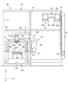
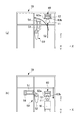
図4は、本実施形態に係る第1反転装置を模式的に示す正面図である。図5は、本実施形態に係る第1反転装置が第2インゴットを反転させた状態を模式的に示す正面図である。
Next, with reference to FIG.4 and FIG.5, the 1st inversion apparatus 4a which concerns on this embodiment is demonstrated. Since the second inverting device 4b has the same configuration as the first inverting device 4a described below, the description thereof is omitted.
FIG. 4 is a front view schematically showing the first reversing device according to the present embodiment. FIG. 5 is a front view schematically showing a state in which the first inversion device according to the present embodiment inverts the second ingot.

図4及び図5に示すように、第1反転装置4aは、第2昇降部40と、回動アーム部50と、第1昇降部60と、支持フレーム70と、を備えて構成されている。   As shown in FIGS. 4 and 5, the first reversing device 4 a includes a second elevating unit 40, a rotating arm unit 50, a first elevating unit 60, and a support frame 70. .

第2昇降部40は、第2保持部41と、第2駆動部42と、を有して構成されている。
第2保持部41は、一対の第2アーム43a,43bと、一対のアーム支持部44a,44bと、を有する。
The second elevating part 40 includes a second holding part 41 and a second driving part 42.
The second holding part 41 includes a pair of second arms 43a and 43b and a pair of arm support parts 44a and 44b.

一対の第2アーム43a,43bは、水平方向における第2インゴットの軸方向と直交する方向(以下、「第1水平方向」という)Xに移動可能に形成されている。具体的には、一対の第2アーム43a,43bは、第1水平方向Xにおいて、互いに近接する方向及び離反する方向に移動可能に形成されている。また、一対の第2アーム43a,43bそれぞれの端部には、第2インゴット11を保持する一対の受け部45a,45bが設けられている。一対の受け部45a,45bは、第2インゴット11の外周面に沿うように曲面状に形成されている。一対の受け部45a,45bは、一対の第2アーム43a,43bが互いに近接する方向に移動することにより、第2インゴット11のインゴットヘッド12を下部側から支えるようにして第2インゴット11を保持するように形成されている。   The pair of second arms 43a and 43b are formed so as to be movable in a direction X (hereinafter referred to as “first horizontal direction”) orthogonal to the axial direction of the second ingot in the horizontal direction. Specifically, the pair of second arms 43a and 43b are formed so as to be movable in the first horizontal direction X in a direction approaching and separating from each other. In addition, a pair of receiving portions 45 a and 45 b that hold the second ingot 11 are provided at end portions of the pair of second arms 43 a and 43 b, respectively. The pair of receiving portions 45 a and 45 b are formed in a curved shape so as to follow the outer peripheral surface of the second ingot 11. The pair of receiving portions 45a and 45b hold the second ingot 11 so as to support the ingot head 12 of the second ingot 11 from the lower side by moving the pair of second arms 43a and 43b in a direction close to each other. It is formed to do.

一対のアーム支持部44a,44bは、一対の第2アーム43a,43bを第1水平方向Xに移動可能に支持する。また、一対のアーム支持部44a,44bは、互いに対向するように配設されており、アーム支持部44aとアーム支持部44bの間には、前述の第2搬送コンベア23が配設可能に形成されている。   The pair of arm support portions 44a and 44b support the pair of second arms 43a and 43b so as to be movable in the first horizontal direction X. Further, the pair of arm support portions 44a and 44b are disposed so as to face each other, and the second conveyor 23 is formed between the arm support portion 44a and the arm support portion 44b. Has been.

第2駆動部42は、一対ガイドレール(図示せず)と、駆動モータ46と、を有する。一対のガイドレールは、一対のアーム支持部44a,44bを垂直方向Zに移動可能に支持する。具体的には、一対のガイドレールは、第2搬送コンベア23により搬送された第2インゴットを一対の受け部45a,45bが受け取り可能な位置(以下、「第1初期位置」という)から、第2インゴット11を後述の回動アーム部50の保持部54に受け渡し可能な位置(以下、「第1の位置」という)に移動可能に一対のアーム支持部44a,44bを支持する。駆動モータ47は、一対のアーム支持部44a,44bを一対のガイドレール47a,47bに沿って第1初期位置から第1の位置に移動させる。   The second drive unit 42 includes a pair of guide rails (not shown) and a drive motor 46. The pair of guide rails support the pair of arm support portions 44a and 44b so as to be movable in the vertical direction Z. Specifically, the pair of guide rails has a first position from a position where the pair of receiving portions 45a and 45b can receive the second ingot transported by the second transport conveyor 23 (hereinafter referred to as "first initial position"). The two ingots 11 are supported by a pair of arm support portions 44a and 44b so as to be movable to a position where the ingot 11 can be transferred to a holding portion 54 of the rotating arm portion 50 to be described later (hereinafter referred to as "first position"). The drive motor 47 moves the pair of arm support portions 44a and 44b from the first initial position to the first position along the pair of guide rails 47a and 47b.

回動アーム部50は、アーム部51と、回動駆動部52と、を有して構成されている。
アーム部51は、保持部54と、アーム本体部55と、を有する。保持部54は、一対の係合部(図示せず)を有する。一対の係合部は、水平方向における第1水平方向Xと直交する方向(以下、「第2水平方向」という)Yに移動可能に形成されている。つまり、一対の係合部は、第2インゴット11の軸方向に移動可能に形成されている。具体的には、一対の係合部は、第2水平方向Yにおいて、互いに近接する方向及び離反する方向に移動可能に形成されている。保持部54は、係合部が互いに近接する方向(Y)に移動することにより、第2インゴット11のインゴットヘッド12と係合し、インゴットヘッド12を保持可能に形成されている。アーム本体部55は、保持部54を第2水平方向Yに移動可能に支持する。
The rotation arm unit 50 includes an arm unit 51 and a rotation drive unit 52.
The arm part 51 includes a holding part 54 and an arm main body part 55. The holding part 54 has a pair of engaging parts (not shown). The pair of engaging portions are formed so as to be movable in a direction Y (hereinafter referred to as “second horizontal direction”) Y orthogonal to the first horizontal direction X in the horizontal direction. That is, the pair of engaging portions are formed to be movable in the axial direction of the second ingot 11. Specifically, the pair of engaging portions are formed so as to be movable in the second horizontal direction Y in a direction approaching and separating from each other. The holding portion 54 is formed so as to be able to hold the ingot head 12 by engaging with the ingot head 12 of the second ingot 11 by moving the engaging portions in a direction (Y) in which the engaging portions approach each other. The arm main body portion 55 supports the holding portion 54 so as to be movable in the second horizontal direction Y.

回動駆動部52は、回動本体部56と、駆動部57と、を有する。回動本体部56は、アーム本体部55を180度回動可能に軸支している。駆動部57は、アーム本体部55を180度回動させる。つまり、駆動部57は、アーム部51を図4に示す第1の位置から図5に示す180度回動させた位置(以下「第2の位置」という)に回動させる。   The rotation drive unit 52 includes a rotation main body unit 56 and a drive unit 57. The rotation main body 56 pivotally supports the arm main body 55 so that it can rotate 180 degrees. The drive unit 57 rotates the arm main body 55 by 180 degrees. That is, the drive unit 57 rotates the arm unit 51 from the first position illustrated in FIG. 4 to a position rotated by 180 degrees illustrated in FIG. 5 (hereinafter referred to as “second position”).

第1昇降部60は、第1保持部61と、第1駆動部62と、を有して構成されている。
第1保持部61は、一対の第1アーム63a,63bと、アーム支持部64と、を有する。
The first elevating / lowering unit 60 includes a first holding unit 61 and a first driving unit 62.
The first holding part 61 has a pair of first arms 63 a and 63 b and an arm support part 64.

一対の第1アーム63a,63bは、第1水平方向Xに移動可能に形成されている。具体的には、一対の第1アーム63a,63bは、第1水平方向Xにおいて、互いに近接する方向及び離反する方向に移動可能に形成されている。また、一対の第1アーム63a,63bそれぞれの端部には、第2インゴット11のインゴットヘッド12を保持する一対の係合部65a,65bが設けられている。一対の係合部65a,65bは、一対の第1アーム63a,63bが互いに近接する方向(X)に移動することにより、インゴットヘッド12と係合し、第2インゴット11を保持可能に形成されている。アーム支持部64は、一対の第1アーム63a,63bを第1水平方向Xに移動可能に支持する。   The pair of first arms 63a and 63b is formed to be movable in the first horizontal direction X. Specifically, the pair of first arms 63a and 63b are formed so as to be movable in the first horizontal direction X toward and away from each other. A pair of engaging portions 65a and 65b that hold the ingot head 12 of the second ingot 11 are provided at the ends of the pair of first arms 63a and 63b. The pair of engaging portions 65a and 65b are formed to be able to engage with the ingot head 12 and hold the second ingot 11 when the pair of first arms 63a and 63b move in a direction (X) in which they are close to each other. ing. The arm support portion 64 supports the pair of first arms 63a and 63b so as to be movable in the first horizontal direction X.

第1駆動部62は、一対のガイドレール(図示せず)と、駆動モータ66と、を有する。一対のガイドレールは、アーム支持部64を垂直方向Zに移動可能に支持する。具体的には、ガイドレールは、第2の位置から回動アーム部の回動を干渉しない位置(以下、「第2初期位置」という)に移動可能にアーム支持部64を支持する。駆動モータ66は、アーム支持部64を一対ガイドレールに沿って図5に示す第2の位置から図4に示す第2初期位置に移動させる。   The first drive unit 62 includes a pair of guide rails (not shown) and a drive motor 66. The pair of guide rails support the arm support portion 64 so as to be movable in the vertical direction Z. Specifically, the guide rail supports the arm support portion 64 so as to be movable from the second position to a position that does not interfere with the rotation of the rotating arm portion (hereinafter referred to as “second initial position”). The drive motor 66 moves the arm support portion 64 along the pair of guide rails from the second position shown in FIG. 5 to the second initial position shown in FIG.

支持フレーム70は、第2昇降部40、回動アーム部50及び第1昇降部60を支持する。具体的には、支持フレーム70は、支持フレーム70の一方側に立設される第1支柱71と、支持フレーム70の他方側に立設される第2支柱72と、第1支柱71と第2支柱72との間に設けられる第3支柱73と、を有して構成されている。第1支柱71と第2支柱との間には、第2昇降部40が設けられる。第2支柱72には、第1昇降部60が取り付けられている。第3支柱73には、回動アーム部50が取り付けられている。   The support frame 70 supports the second elevating unit 40, the rotating arm unit 50, and the first elevating unit 60. Specifically, the support frame 70 includes a first support 71 standing on one side of the support frame 70, a second support 72 standing on the other side of the support frame 70, a first support 71, And a third support column 73 provided between the two support columns 72. Between the 1st support | pillar 71 and the 2nd support | pillar, the 2nd raising / lowering part 40 is provided. A first elevating unit 60 is attached to the second support column 72. A rotating arm unit 50 is attached to the third support column 73.

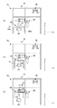
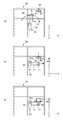
次に、図6(a)から図8(b)を参照して、本実施形態に係る第1反転装置4aの動作について説明する。図6(a)は、第3コンベアにより第2昇降部に第2インゴットが搬送された状態を模式的に示す正面図である。図6(b)は、第2昇降部が第2インゴットを保持した状態で上昇する状態を模式的に示す正面図である。図6(c)は、回動アーム部が第2インゴットを保持する状態を模式的に示す正面図である。図7(a)は、回転アーム部が第2インゴットを保持して回動する状態を模式的に示す正面図である。図7(b)は、第2インゴットを保持した回転アーム部が第2の位置へ移動し、第1昇降部が下降する状態を模式的に示す正面図である。図7(c)は、第2の位置で第1昇降部が第2インゴットを保持する状態を模式的に示す正面図である。図8(a)は、第1昇降部が第2インゴットを保持した状態で上昇すると共に、回動アーム部が第2の位置から回動する状態を模式的に示す正面図である。図8(b)は、回動アームが第1の位置に移動すると共に、第1昇降部が搬送台車に第2インゴットを載置した状態を模式的に示す正面図である。   Next, with reference to FIG. 6A to FIG. 8B, the operation of the first inversion device 4a according to the present embodiment will be described. Fig.6 (a) is a front view which shows typically the state by which the 2nd ingot was conveyed to the 2nd raising / lowering part by the 3rd conveyor. FIG.6 (b) is a front view which shows typically the state which raises in the state which the 2nd raising / lowering part hold | maintained the 2nd ingot. FIG.6 (c) is a front view which shows typically the state in which a rotation arm part hold | maintains a 2nd ingot. FIG. 7A is a front view schematically showing a state in which the rotating arm portion rotates while holding the second ingot. FIG. 7B is a front view schematically showing a state where the rotating arm portion holding the second ingot moves to the second position and the first elevating portion descends. FIG.7 (c) is a front view which shows typically the state in which a 1st raising / lowering part hold | maintains a 2nd ingot in a 2nd position. FIG. 8A is a front view schematically showing a state in which the first elevating unit moves up while holding the second ingot and the rotating arm unit rotates from the second position. FIG. 8B is a front view schematically showing a state in which the rotating arm moves to the first position and the first elevating unit places the second ingot on the transport carriage.

第2保管部21で所定時間乾燥された第2インゴット11は、スライス処理工程を行うために、第2搬送コンベア23により、第1反転装置4aに移動される。具体的には、図6(a)に示すように、第2搬送コンベア23により第1反転装置4aに移動された第2インゴット11は、第1初期位置にあるアーム支持部44aとアーム支持部44bの間に搬送される。   The second ingot 11 dried for a predetermined time in the second storage unit 21 is moved to the first reversing device 4a by the second transport conveyor 23 in order to perform the slicing process. Specifically, as shown in FIG. 6A, the second ingot 11 moved to the first reversing device 4a by the second transport conveyor 23 includes the arm support 44a and the arm support in the first initial position. 44b.

第2インゴット11がアーム支持部44aとアーム支持部44bの間に搬送されると、第2アーム43aと第2アーム43bとが、互いに近接する方向(X)に移動する。第2アーム43aと第2アーム43bとが、互いに近接する方向(X)に移動すると、第2アーム43aの先端に設けられた受け部45aと、第2アーム43bの先端に設けられた受け部45bとが第2インゴット11の外周面に当接する。受け部45aと受け部45bとがインゴットヘッド12の下部を支持すると、第2アーム43aと第2アーム43bの移動が止まる。このようにして、第2搬送コンベア23により搬送された第2インゴット11は、第2搬送コンベア23により搬送された態勢のまま第2保持部41に保持される。   If the 2nd ingot 11 is conveyed between the arm support part 44a and the arm support part 44b, the 2nd arm 43a and the 2nd arm 43b will move to the direction (X) which mutually adjoins. When the second arm 43a and the second arm 43b move in the direction (X) in which they are close to each other, the receiving portion 45a provided at the tip of the second arm 43a and the receiving portion provided at the tip of the second arm 43b 45b contacts the outer peripheral surface of the second ingot 11. When the receiving part 45a and the receiving part 45b support the lower part of the ingot head 12, the movement of the second arm 43a and the second arm 43b stops. Thus, the 2nd ingot 11 conveyed by the 2nd conveyance conveyor 23 is hold | maintained at the 2nd holding | maintenance part 41 with the state conveyed by the 2nd conveyance conveyor 23. FIG.

次いで、第2インゴット11が第2保持部41に保持されると、図6(b)に示すように、第2駆動部42が第2保持部41を上昇させる。具体的には、第2駆動部42は、第2インゴット11を保持した第2保持部41を図6(a)に示す第1初期位置から図6(c)に示す第1の位置に移動させる。なお、図6(b)は、第1初期位置から第1の位置に移動する第2保持部41を示している。   Next, when the second ingot 11 is held by the second holding part 41, the second driving part 42 raises the second holding part 41 as shown in FIG. Specifically, the second drive unit 42 moves the second holding unit 41 holding the second ingot 11 from the first initial position shown in FIG. 6A to the first position shown in FIG. 6C. Let FIG. 6B shows the second holding portion 41 that moves from the first initial position to the first position.

図6(c)に示すように、第2インゴット11が保持された第2保持部41が第1の位置に移動すると、アーム部51が第1の位置で第2保持部41に保持された第2インゴット11を掴む。具体的には、アーム部51に設けられる保持部54が第2水平方向Yに移動して第2インゴット11の軸方向から第2インゴット11を掴む。ここで、図6(c)に示す第1の位置において、第2インゴット11は、第2保持部41に外周面を当接させた状態で保持されている。一方、アーム部51は、第2インゴット11を第2インゴット11の軸方向から掴み、保持する。つまり、アーム部51は、図6(c)に示す第1の位置において、第2保持部41に干渉されることなく第2インゴット11を保持することが可能になる。   As shown in FIG. 6C, when the second holding portion 41 holding the second ingot 11 moves to the first position, the arm portion 51 is held by the second holding portion 41 at the first position. Grab the second ingot 11. Specifically, the holding portion 54 provided in the arm portion 51 moves in the second horizontal direction Y and grips the second ingot 11 from the axial direction of the second ingot 11. Here, in the 1st position shown in FIG.6 (c), the 2nd ingot 11 is hold | maintained in the state which made the 2nd holding part 41 contact | abut the outer peripheral surface. On the other hand, the arm part 51 grips and holds the second ingot 11 from the axial direction of the second ingot 11. That is, the arm part 51 can hold the second ingot 11 without being interfered with the second holding part 41 at the first position shown in FIG.

図7(b)に示すように、アーム部51が第2インゴット11を保持すると、回動駆動部52が第2インゴット11を保持したアーム部51を180度回動させる。言い換えると、回動駆動部52が第2インゴット11を図6(c)に示す第1の位置から図7(b)に示す第2の位置に移動させる。第2インゴット11は、回動駆動部52によりアーム部51が180度回動されることにより、第2搬送コンベア23により搬送された状態から反転された状態になる。つまり、第2インゴット11は、インゴットヘッド12が上方にある態勢になる。   As shown in FIG. 7B, when the arm unit 51 holds the second ingot 11, the rotation driving unit 52 rotates the arm unit 51 holding the second ingot 11 by 180 degrees. In other words, the rotation drive unit 52 moves the second ingot 11 from the first position shown in FIG. 6C to the second position shown in FIG. The second ingot 11 is inverted from the state conveyed by the second conveyor 23 when the arm 51 is rotated 180 degrees by the rotation drive unit 52. In other words, the second ingot 11 is in a state where the ingot head 12 is on the upper side.

回動アーム部50により、第2インゴット11が図7(b)に示す第2の位置に移動されると、図7(b)に示すように、第1保持部61が図7(a)に示す第2初期位置から図7(c)に示す第2の位置に向かって下降する。第1保持部61が第2の位置に到達すると、第1保持部61は、第1アーム63aと第1アーム63bとを移動させ、第1水平方向Xから第2インゴット11のインゴットヘッド12を掴み、第2インゴット11を保持する(図7(c)参照)。第1保持部61が第2インゴット11を保持すると、回動アーム部50は、保持部54を移動させ、第2インゴット11を離す。   When the second ingot 11 is moved to the second position shown in FIG. 7B by the rotating arm 50, as shown in FIG. 7B, the first holding part 61 is shown in FIG. 7A. Is lowered from the second initial position shown in FIG. 7 toward the second position shown in FIG. When the first holding unit 61 reaches the second position, the first holding unit 61 moves the first arm 63a and the first arm 63b, and moves the ingot head 12 of the second ingot 11 from the first horizontal direction X. Grasping and holding the second ingot 11 (see FIG. 7C). When the first holding unit 61 holds the second ingot 11, the rotating arm unit 50 moves the holding unit 54 and releases the second ingot 11.

図8(a)に示すように、回動アーム部50が第2インゴット11を離すと、第1昇降部60は、図7(c)に示す第2の位置から図7(a)に示す第2初期位置に向かって上昇する。図8(a)に示すように、第1昇降部60が上昇すると、回動アーム部50が第2の位置から第1の位置に向かって回動する。   As shown in FIG. 8A, when the rotating arm unit 50 releases the second ingot 11, the first elevating unit 60 is shown in FIG. 7A from the second position shown in FIG. 7C. It rises toward the second initial position. As shown in FIG. 8A, when the first elevating / lowering unit 60 moves up, the rotating arm unit 50 rotates from the second position toward the first position.

図8(b)に示すように、回動アーム部50が図7(c)に示す第2の位置から図8(b)に示す第1の位置に回動すると、第1昇降部60の下方側における所定の位置に搬送台車Wが搬入される。搬送台車Wが所定の位置に搬入されると、第1保持部61が搬送台車Wに向かって降下し、インゴットヘッド12が上方にある態勢の第2インゴット11を搬送台車Wに載置する。第2インゴット11が搬送台車Wに載置されると、搬送台車Wが第1スライス装置5aに移動され、第2インゴット11が第1スライス装置5aにより、所定の厚さにスライスされる。本実施形態に係る第1反転装置4a上述の動作を繰り返し行う。   As shown in FIG. 8B, when the turning arm 50 is turned from the second position shown in FIG. 7C to the first position shown in FIG. The transport cart W is carried into a predetermined position on the lower side. When the transport cart W is carried into a predetermined position, the first holding unit 61 descends toward the transport cart W, and the second ingot 11 with the ingot head 12 in an upper position is placed on the transport cart W. When the second ingot 11 is placed on the transport cart W, the transport cart W is moved to the first slicing device 5a, and the second ingot 11 is sliced to a predetermined thickness by the first slicing device 5a. The first inverting device 4a according to the present embodiment repeats the above-described operation.

以上のように構成された本実施形態に係る第1反転装置4aによれば、以下のような効果が奏される。
本実施形態によると、第1反転装置4aは、第2インゴット11を反転させる回動アーム部50と、回動アーム部50により反転された第2インゴット11を保持する第1昇降部と、を有する。そのため、例えば、大径の半導体インゴットのような重量物を傷つけることなく容易に反転させることが可能になる。
According to the 1st inversion apparatus 4a which concerns on this embodiment comprised as mentioned above, there exist the following effects.
According to the present embodiment, the first reversing device 4a includes the rotating arm unit 50 that reverses the second ingot 11 and the first elevating unit that holds the second ingot 11 reversed by the rotating arm unit 50. Have. Therefore, for example, it is possible to easily invert without damaging a heavy object such as a large-diameter semiconductor ingot.

また、本実施形態によると、例えば、第1インゴット10の接着処理工程から第2インゴット11を反転させる工程までを無人化することが可能になる。そのため、作業者が重量物を扱う必要がなくなり、安全性を向上させることが可能になる。   Further, according to the present embodiment, for example, it is possible to unmanned from the bonding process step of the first ingot 10 to the step of inverting the second ingot 11. This eliminates the need for the operator to handle heavy objects and improves safety.

また、本実施形態によると、アーム部51は、第2インゴット11を保持した第1保持部61が上昇した後、第2インゴット11を保持しない状態で第2の位置から回動駆動部52により回動され、第1保持部61は、アーム部51が第2の位置から回動した後、第1駆動部62により下降される。そのため、アーム部51は、第1保持部61に干渉されることなく第1の位置に戻ることが可能となる。また、第1保持部61は、アーム部51に干渉されることなく第2の位置に戻ると共に、第2インゴット11を搬送台車Wに載置させることが可能となる。つまり、容易に搬送台車Wに第2インゴット11を載置させることが可能になる。   Further, according to the present embodiment, the arm unit 51 is moved from the second position by the rotation driving unit 52 without holding the second ingot 11 after the first holding unit 61 holding the second ingot 11 is lifted. The first holding unit 61 is rotated and lowered by the first driving unit 62 after the arm unit 51 is rotated from the second position. Therefore, the arm part 51 can return to the first position without being interfered with the first holding part 61. Further, the first holding unit 61 can return to the second position without being interfered with the arm unit 51 and can place the second ingot 11 on the transport carriage W. That is, the second ingot 11 can be easily placed on the transport carriage W.

なお、本発明の実施形態は、上記の実施形態に何ら限定されることなく、本発明の技術的範囲は、これに限定されるものではない。例えば、本実施形態においては、アーム部51は、間接的に第2インゴット11を保持する構成としたが、本発明においてはこれに限定されない。例えば、アーム部51は、第2インゴット11を直接的に保持する構成としてもよい。   In addition, embodiment of this invention is not limited to said embodiment at all, and the technical scope of this invention is not limited to this. For example, in the present embodiment, the arm portion 51 is configured to indirectly hold the second ingot 11, but the present invention is not limited to this. For example, the arm part 51 is good also as a structure which hold | maintains the 2nd ingot 11 directly.

また、本実施形態においては、第1保持部61は、間接的に第2インゴット11を保持する構成としたが、本発明においてはこれに限定されない。例えば、第1保持部61は、第2インゴット11を直接的に保持する構成としてもよい。   Moreover, in this embodiment, although the 1st holding | maintenance part 61 was set as the structure which hold | maintains the 2nd ingot 11 indirectly, in this invention, it is not limited to this. For example, the first holding unit 61 may be configured to hold the second ingot 11 directly.

さらに、本実施形態においては、第2保持部41は、直接的に第2インゴット11を保持する構成としたが本発明においてはこれに限定されない。例えば、第2保持部41は、第2インゴット11を間接的に保持する構成としてもよい。   Further, in the present embodiment, the second holding portion 41 is configured to hold the second ingot 11 directly, but the present invention is not limited to this. For example, the second holding unit 41 may be configured to indirectly hold the second ingot 11.

また、本実施形態においては、アーム部51を180度回動させる構成としたが、本発明においてはこれに限定されない。例えば、180度以上回動させる構成であってもよく、180度以下回動させる構成であってもよい。   In the present embodiment, the arm portion 51 is rotated 180 degrees, but the present invention is not limited to this. For example, the structure rotated 180 degrees or more may be sufficient and the structure rotated 180 degrees or less may be sufficient.

また、本実施形態においては、第1インゴット(半導体インゴット)10は、シリコンを原料として製造されたものを用いて説明したが、本発明においてはこれに限らない。例えば、第1インゴット(半導体インゴット)は、GaA、InP、ZnS、ZnSeを原料として製造されたものであってもよい。   In the present embodiment, the first ingot (semiconductor ingot) 10 has been described as being manufactured using silicon as a raw material. However, the present invention is not limited to this. For example, the first ingot (semiconductor ingot) may be manufactured using GaA, InP, ZnS, or ZnSe as a raw material.

本実施形態に係る第1反転装置を備えるインゴットスライスシステムの概略構成を示す平面図である。It is a top view showing a schematic structure of an ingot slice system provided with the 1st inversion device concerning this embodiment. 図1に示すインゴットスライスシステムの概略構成を示す正面図である。It is a front view which shows schematic structure of the ingot slice system shown in FIG. 本実施形態に係る第1反転装置により反転される第2インゴットを示す外観斜視図である。It is an external appearance perspective view which shows the 2nd ingot reversed by the 1st inversion apparatus which concerns on this embodiment. 本実施形態に係る第1反転装置を模式的に示す正面図である。It is a front view showing typically the 1st inversion device concerning this embodiment. 本実施形態に係る第1反転装置が第2インゴットを反転させた状態を模式的に示す正面図である。It is a front view showing typically the state where the 1st inversion device concerning this embodiment reversed the 2nd ingot. (a)は、第3コンベアにより第2昇降部に第2インゴットが搬送された状態を模式的に示す正面図であり、(b)は、第2昇降部が第2インゴットを保持した状態で上昇する状態を模式的に示す正面図であり、(c)は、回動アーム部が第2インゴットを保持する状態を模式的に示す正面図である。(A) is a front view which shows typically the state where the 2nd ingot was conveyed to the 2nd raising / lowering part by the 3rd conveyor, (b) is the state in which the 2nd raising / lowering part hold | maintained the 2nd ingot. It is a front view which shows the state which raises typically, (c) is a front view which shows typically the state in which a rotation arm part hold | maintains a 2nd ingot. (a)は、回転アーム部が第2インゴットを保持して回動する状態を模式的に示す正面図であり、(b)は、第2インゴットを保持した回転アーム部が第2の位置へ移動し、第1昇降部が下降する状態を模式的に示す正面図であり、(c)は、第2の位置で第1昇降部が第2インゴットを保持する状態を模式的に示す正面図である。(A) is a front view which shows typically the state in which a rotation arm part hold | maintains a 2nd ingot, and rotates, (b) is a rotation arm part holding the 2nd ingot to a 2nd position. It is a front view which shows the state which moves and the 1st raising / lowering part descend | falls, (c) is a front view which shows typically the state in which a 1st raising / lowering part hold | maintains a 2nd ingot in a 2nd position. It is. (a)は、第1昇降部が第2インゴットを保持した状態で上昇すると共に、回動アーム部が第2の位置から回動する状態を模式的に示す正面図であり、(b)は、回動アームが第1の位置に移動すると共に、第1昇降部が搬送台車に第2インゴットを載置した状態を模式的に示す正面図である。(A) is a front view schematically showing a state in which the first elevating part is lifted while holding the second ingot and the turning arm part is turned from the second position. FIG. 5 is a front view schematically showing a state where the rotating arm moves to the first position and the first elevating unit places the second ingot on the transport carriage.

符号の説明Explanation of symbols

1 インゴットスライスシステム
4a 第1反転装置(半導体インゴット反転装置)
4b 第2反転装置(半導体インゴット反転装置)
10 第1インゴット
11 第2インゴット(半導体インゴット)
40 第2保持部
50 回転アーム部
51 アーム部
52 回転駆動部
60 第1昇降部
61 第1保持部
62 第1駆動部
DESCRIPTION OF SYMBOLS 1 Ingot slice system 4a 1st inversion apparatus (semiconductor ingot inversion apparatus)
4b Second reversing device (semiconductor ingot reversing device)
10 1st ingot 11 2nd ingot (semiconductor ingot)
40 Second holding part 50 Rotating arm part 51 Arm part 52 Rotation driving part 60 First lifting part 61 First holding part 62 First driving part

Claims (5)

略円柱状の半導体インゴットを直接的に又は間接的に保持可能なアーム部と、前記アーム部を第1の位置から第2の位置に回動させる回動駆動部と、を有する回動アーム部と、
前記回動アーム部により前記第2の位置に移動された前記半導体インゴットを直接的に又は間接的に保持可能な第1保持部と、前記第1保持部を上下方向に昇降させる第1駆動部と、を有する第1昇降部と、
を備える半導体インゴット反転装置。
Rotating arm portion having an arm portion capable of directly or indirectly holding a substantially cylindrical semiconductor ingot, and a rotation driving portion for rotating the arm portion from the first position to the second position. When,
A first holding unit capable of directly or indirectly holding the semiconductor ingot moved to the second position by the rotating arm unit, and a first driving unit for moving the first holding unit up and down A first lifting part having
A semiconductor ingot reversing device.
前記回動駆動部は、前記アーム部を180度回動させる請求項1に記載の半導体インゴット反転装置。   The semiconductor ingot reversing device according to claim 1, wherein the rotation driving unit rotates the arm unit by 180 degrees. 前記第1の位置に位置する前記半導体インゴットを直接的に又は間接的に保持可能な第2保持部と、前記第2保持部を上下方向に昇降させる第2駆動部と、を有する第2昇降部を更に備える請求項1又は2に記載の半導体インゴット反転装置。   A second elevating unit having a second holding unit capable of directly or indirectly holding the semiconductor ingot positioned at the first position, and a second driving unit for moving the second holding unit up and down. The semiconductor ingot inverting device according to claim 1, further comprising a unit. 半導体インゴットの外周面の一部には、固着部材が固着され、
前記第1保持部は、前記固着部材を介して前記半導体インゴットを間接的に保持する請求項3に記載の半導体シリコン反転装置。
A fixing member is fixed to a part of the outer peripheral surface of the semiconductor ingot,
4. The semiconductor silicon inversion device according to claim 3, wherein the first holding unit indirectly holds the semiconductor ingot via the fixing member.
前記アーム部は、前記半導体インゴットを保持した前記第1保持部が上昇した後、前記半導体インゴットを保持しない状態で前記第2の位置から回動駆動部により回動され、
前記第1保持部は、前記アーム部が前記第2の位置から回動した後、前記第1駆動部により下降される請求項1から4のいずれかに記載の半導体インゴット反転装置。
The arm portion is rotated by the rotation driving unit from the second position without holding the semiconductor ingot after the first holding unit holding the semiconductor ingot is raised,
5. The semiconductor ingot reversing device according to claim 1, wherein the first holding unit is lowered by the first driving unit after the arm unit is rotated from the second position. 6.
JP2008320664A 2008-12-17 2008-12-17 Semiconductor ingot reversing device Expired - Fee Related JP5417833B2 (en)

Priority Applications (1)

Application Number Priority Date Filing Date Title
JP2008320664A JP5417833B2 (en) 2008-12-17 2008-12-17 Semiconductor ingot reversing device

Applications Claiming Priority (1)

Application Number Priority Date Filing Date Title
JP2008320664A JP5417833B2 (en) 2008-12-17 2008-12-17 Semiconductor ingot reversing device

Publications (2)

Publication Number Publication Date
JP2010143674A true JP2010143674A (en) 2010-07-01
JP5417833B2 JP5417833B2 (en) 2014-02-19

Family

ID=42564508

Family Applications (1)

Application Number Title Priority Date Filing Date
JP2008320664A Expired - Fee Related JP5417833B2 (en) 2008-12-17 2008-12-17 Semiconductor ingot reversing device

Country Status (1)

Country Link
JP (1) JP5417833B2 (en)

Cited By (1)

* Cited by examiner, † Cited by third party
Publication number Priority date Publication date Assignee Title
WO2024166546A1 (en) * 2023-02-06 2024-08-15 株式会社トクヤマ Inversion device, imaging device, inversion method, and imaging method

Citations (5)

* Cited by examiner, † Cited by third party
Publication number Priority date Publication date Assignee Title
JPS59124605A (en) * 1982-12-29 1984-07-18 Komai Tekkosho:Kk Plate-like object reversing device
JPH11186199A (en) * 1997-12-17 1999-07-09 Tokyo Seimitsu Co Ltd Ingot mounting device
JPH11348547A (en) * 1998-06-12 1999-12-21 Calsonic Corp Heavy object reversing device
JP2000302218A (en) * 1999-04-21 2000-10-31 Kanto Auto Works Ltd Work reversing device
JP2002012176A (en) * 2000-06-28 2002-01-15 Daihatsu Motor Co Ltd Cylinder block reversing device

Patent Citations (5)

* Cited by examiner, † Cited by third party
Publication number Priority date Publication date Assignee Title
JPS59124605A (en) * 1982-12-29 1984-07-18 Komai Tekkosho:Kk Plate-like object reversing device
JPH11186199A (en) * 1997-12-17 1999-07-09 Tokyo Seimitsu Co Ltd Ingot mounting device
JPH11348547A (en) * 1998-06-12 1999-12-21 Calsonic Corp Heavy object reversing device
JP2000302218A (en) * 1999-04-21 2000-10-31 Kanto Auto Works Ltd Work reversing device
JP2002012176A (en) * 2000-06-28 2002-01-15 Daihatsu Motor Co Ltd Cylinder block reversing device

Cited By (1)

* Cited by examiner, † Cited by third party
Publication number Priority date Publication date Assignee Title
WO2024166546A1 (en) * 2023-02-06 2024-08-15 株式会社トクヤマ Inversion device, imaging device, inversion method, and imaging method

Also Published As

Publication number Publication date
JP5417833B2 (en) 2014-02-19

Similar Documents

Publication Publication Date Title
JP5035415B2 (en) Ceiling transport vehicle
CN112912321B (en) Ceiling Suspended Shelf
TWI571954B (en) Substrate processing system and substrate reversing device
KR100488389B1 (en) Transport facility
US7426883B2 (en) Substrate-cutting system, substrate-producing apparatus, substrate-scribing method, and substrate-cutting method
JP6690709B2 (en) Transport system
KR102184615B1 (en) Transport device
CN108466811B (en) cargo truck
CN108367450A (en) Work conveyance system and work carrying method
CN107804640A (en) Apparatus for handling goods
JP2011051048A (en) Carrying system, robot device, and carrying method
KR20150029518A (en) Substrate inverting and conveying device
KR102422164B1 (en) Conveyer, conveying apparatus, and scribing system
CN1895971A (en) System for transferring flat panel display substrates during manufacture
KR20140061279A (en) Hand for conveying substrate and method for conveying substrate
JP2017109231A (en) Product pallet, workpiece conveyance system, and workpiece conveyance method
JP5417833B2 (en) Semiconductor ingot reversing device
KR20130011907A (en) Dividing apparatus
KR102525334B1 (en) Scribing apparatus
JP5422996B2 (en) Semiconductor ingot transfer system
JP5928304B2 (en) Board transfer equipment
JP2018069247A (en) Work transfer system and work transfer method
JP2018069248A (en) Laser processing system
JP2009184422A (en) Unmanned conveying truck
JP2005064431A (en) Substrate transport apparatus and substrate transport method

Legal Events

Date Code Title Description
A621 Written request for application examination

Free format text: JAPANESE INTERMEDIATE CODE: A621

Effective date: 20111216

A131 Notification of reasons for refusal

Free format text: JAPANESE INTERMEDIATE CODE: A131

Effective date: 20130618

A521 Request for written amendment filed

Free format text: JAPANESE INTERMEDIATE CODE: A523

Effective date: 20130801

TRDD Decision of grant or rejection written
A01 Written decision to grant a patent or to grant a registration (utility model)

Free format text: JAPANESE INTERMEDIATE CODE: A01

Effective date: 20131022

A61 First payment of annual fees (during grant procedure)

Free format text: JAPANESE INTERMEDIATE CODE: A61

Effective date: 20131104

R150 Certificate of patent or registration of utility model

Ref document number: 5417833

Country of ref document: JP

Free format text: JAPANESE INTERMEDIATE CODE: R150

Free format text: JAPANESE INTERMEDIATE CODE: R150

R250 Receipt of annual fees

Free format text: JAPANESE INTERMEDIATE CODE: R250

R250 Receipt of annual fees

Free format text: JAPANESE INTERMEDIATE CODE: R250

R250 Receipt of annual fees

Free format text: JAPANESE INTERMEDIATE CODE: R250

R250 Receipt of annual fees

Free format text: JAPANESE INTERMEDIATE CODE: R250

R250 Receipt of annual fees

Free format text: JAPANESE INTERMEDIATE CODE: R250

R250 Receipt of annual fees

Free format text: JAPANESE INTERMEDIATE CODE: R250

R250 Receipt of annual fees

Free format text: JAPANESE INTERMEDIATE CODE: R250

R250 Receipt of annual fees

Free format text: JAPANESE INTERMEDIATE CODE: R250

LAPS Cancellation because of no payment of annual fees