JP2010143661A - Hoisting machine for elevator, and driving motor therefor - Google Patents
Hoisting machine for elevator, and driving motor therefor Download PDFInfo
- Publication number
- JP2010143661A JP2010143661A JP2008319865A JP2008319865A JP2010143661A JP 2010143661 A JP2010143661 A JP 2010143661A JP 2008319865 A JP2008319865 A JP 2008319865A JP 2008319865 A JP2008319865 A JP 2008319865A JP 2010143661 A JP2010143661 A JP 2010143661A
- Authority
- JP
- Japan
- Prior art keywords
- sheave
- rotor
- main shaft
- elevator
- side wall
- Prior art date
- Legal status (The legal status is an assumption and is not a legal conclusion. Google has not performed a legal analysis and makes no representation as to the accuracy of the status listed.)
- Granted
Links
- 238000004804 winding Methods 0.000 claims description 10
- 239000000725 suspension Substances 0.000 claims description 5
- 238000000034 method Methods 0.000 description 3
- 238000005266 casting Methods 0.000 description 2
- 230000002093 peripheral effect Effects 0.000 description 2
- XEEYBQQBJWHFJM-UHFFFAOYSA-N Iron Chemical group [Fe] XEEYBQQBJWHFJM-UHFFFAOYSA-N 0.000 description 1
- 239000000470 constituent Substances 0.000 description 1
- 238000009434 installation Methods 0.000 description 1
Images

Abstract
Description
本発明は、機械室レスエレベータ用の薄型に適した、エレベータ用巻上機及びその駆動モータに関する。 The present invention relates to an elevator hoist suitable for a machine room-less elevator and a drive motor thereof.
エレベータの巻上機や巻上機の駆動モータの制御装置などは、ビル最上部に配置された専用の機械室内に設置されるのが一般的であるが、機械室レスエレベータと呼ばれる専用の機械室が無いエレベータがある。機械室レスエレベータの場合、巻上機や制御装置など、専用の機械室内に設置していたもの全てを、乗りかごが昇降する昇降路に設置する必要がある。巻上機の形状や設置形態は種々あるが、例えば、乗りかごと昇降路壁の間にある数百mm程度の隙間に巻上機を設置する形態では、扁平形状の巻上機が必要であり、ここではいわゆる薄形巻上機が使用される。 Elevator hoisting machines and hoisting motor drive motor control devices are generally installed in a dedicated machine room located at the top of the building, but a dedicated machine called machine room-less elevator There is an elevator without a room. In the case of a machine room-less elevator, it is necessary to install everything that has been installed in a dedicated machine room, such as a hoisting machine and a control device, in a hoistway where the car goes up and down. There are various types of hoisting machines and installation forms.For example, in a form in which the hoisting machine is installed in a gap of about several hundred mm between the carriage and the hoistway wall, a flat hoisting machine is required. Yes, so-called thin hoisting machines are used here.
薄形巻上機に関する公知技術としては、特許文献1(再公表WO2005/019085号公報)、特許文献2(特開2004-91215号公報)、特許文献3(特開2005-12948号公報)、および特許文献4(特開2004-338915号公報)などに記載の技術がある。 Known techniques related to thin hoisting machines include Patent Document 1 (Republished WO2005 / 019085), Patent Document 2 (JP 2004-91215), Patent Document 3 (JP 2005-12948), And a technique described in Patent Document 4 (Japanese Patent Laid-Open No. 2004-338915).
いずれも同様な構成を有しており、特許文献1を例にすると、筐体を固定するための基体202(脚部)と、主軸を支持するための軸受240(支持部材)があり、それらを互いに接続するための基体には基体底面204(側壁)があり、基体202と軸受240が接続される。また、他の特許文献も参照すると、筐体の側壁全てが綱車と回転子の間に配置されたものでは無く、側壁の全て、あるいは少なくとも側壁の一部は、回転子の綱車と反対側に配置されているか、綱車の回転子と反対側に配置されている。即ち、側壁の一方側に綱車と回転子が配置されている。また、回転子と綱車は一体構造、または回転子が綱車を直接駆動する構造であり、回転子と綱車を近接して接続するための接続部材が必ず存在する。 All of them have the same configuration. For example, Patent Document 1 includes a base body 202 (leg portion) for fixing the housing and a bearing 240 (support member) for supporting the main shaft. The base for connecting the two to each other has a base bottom surface 204 (side wall), and the base 202 and the bearing 240 are connected. Further, referring to other patent documents, not all the side walls of the casing are arranged between the sheave and the rotor, and all of the side walls, or at least a part of the side walls, are opposite to the rotor sheave. It is arranged on the side or on the opposite side of the sheave rotor. That is, the sheave and the rotor are arranged on one side of the side wall. Further, the rotor and the sheave are of an integral structure, or the rotor directly drives the sheave, and there is always a connection member for connecting the rotor and the sheave close to each other.
上記の薄型巻上機やその駆動モータに更なる薄型化を実施する場合、各構成要素の更なる薄型化や、各構成要素間の隙間を減らすなどの方法が考えられる。各構成要素の薄型化に関して、筐体の側壁と、回転子と綱車を接続する部材の、2要素の薄肉化に注目すると、前述の2要素の厚さは強度や剛性などから最小の厚さが決まり、その最小厚さよりも薄肉化することはできない。 In the case of further thinning the above-described thin hoisting machine and its drive motor, methods such as further thinning each component and reducing a gap between the components can be considered. Regarding the thinning of each component, paying attention to the thinning of the two elements of the side wall of the housing and the member connecting the rotor and sheave, the thickness of the two elements mentioned above is the minimum thickness due to strength and rigidity. Therefore, it cannot be made thinner than its minimum thickness.
例えば、筐体が鋳造品である場合、筐体の側壁における強度・剛性に影響しない部分を凹状にすることは簡単であり、肉抜きによって質量の削減は可能になるが、肝心の巻上機全体の厚さを更に薄くするにはことはできない。これは筐体側壁の配置位置に原因があり、前述したように側壁の一方側に綱車と回転子が配置され、しかも綱車と回転子が接続部材で近接接続された状態で、網車に巻き掛けられるロープが接続部材に近接して通過するため、ロープと接続部材の接触防止上、綱車と回転子の厚さ分と、両者の隙間分が必要となるためである。 For example, when the case is a cast product, it is easy to make the concave part in the side wall of the case that does not affect the strength and rigidity. The overall thickness cannot be further reduced. This is caused by the position of the side wall of the housing. As described above, the sheave and the rotor are arranged on one side of the side wall, and the sheave and the rotor are connected in proximity by the connecting member, This is because the rope wound around the wire passes close to the connecting member, and therefore, the thickness of the sheave and the rotor and the gap between them are necessary to prevent contact between the rope and the connecting member.
すなわち、前記の接続部材に凹状の溝を設けて肉抜きするとともに、その溝部をロープが通過するような構成とし、ロープの通過位置を筐体の側に寄せること可能であり、寄せた分だけ巻上機全体の薄型化が可能となる。しかし、これは綱車が回転しない時にのみ適用可能であり、実際には、綱車は必ず回転するので、綱車の回転とともに前記接続部材の凹状の溝も回転し、溝とロープが接触してしまう。したがって、前述の接続部材の肉抜きによる巻上機全体の薄型化も実現困難である。 That is, it is possible to provide a concave groove on the connecting member to make it thin, and to allow the rope to pass through the groove, so that the rope passing position can be brought closer to the housing side. The whole hoisting machine can be thinned. However, this can only be applied when the sheave does not rotate. Actually, since the sheave always rotates, the concave groove of the connecting member also rotates as the sheave rotates, and the groove and the rope come into contact with each other. End up. Therefore, it is difficult to reduce the thickness of the whole hoisting machine by thinning the connecting member.
本発明の目的は、従来技術の課題を解決し、筐体側壁の肉抜きによって巻上機全体の薄型化を可能とする薄型の巻上機及びその駆動モータを提供することにある。 An object of the present invention is to solve the problems of the prior art and to provide a thin hoisting machine and its drive motor that can reduce the thickness of the entire hoisting machine by thinning the side wall of the casing.
本発明は、上記課題を解決するため、エレベータの懸垂荷重を支持する筐体と、上記筐体内に設置された軸受によって回転自在に支持された主軸と、上記主軸に接合された綱車と、上記主軸に接合されたモータの回転子と、上記回転子に対向して配置されるモータの固定子を有する巻上機において、
上記筐体は上記軸受が設置された側壁を有し、
上記綱車と上記モータの回転子とはこの側壁を挟むように上記主軸の両端に固定され、
上記側壁は上記綱車側に設けられた凹状の溝を有し、
上記回転子の回転力が上記主軸を介して上記綱車に伝達されるに際し、上記綱車に巻き掛けられたロープが上記溝を通過するように構成されたことを特徴とする。
In order to solve the above problems, the present invention provides a housing that supports a suspension load of an elevator, a main shaft that is rotatably supported by a bearing installed in the housing, a sheave joined to the main shaft, In a hoisting machine having a rotor of a motor joined to the main shaft and a stator of a motor arranged to face the rotor,
The housing has a side wall on which the bearing is installed,
The sheave and the rotor of the motor are fixed to both ends of the main shaft so as to sandwich the side wall,
The side wall has a concave groove provided on the sheave side,
When the rotational force of the rotor is transmitted to the sheave via the main shaft, the rope wound around the sheave is configured to pass through the groove.
また、上記に記載のエレベータ用巻上機において、上記綱車の一部が上記側壁の内部に入り込めるように、上記側壁の上記綱車側に上記溝に連通した環状の凹みが設けられたことを特徴とする。 In the elevator hoist described above, an annular recess communicated with the groove is provided on the sheave side of the side wall so that a part of the sheave can enter the inside of the side wall. It is characterized by.
また、上記に記載のエレベータ用巻上機において、上記筐体は脚部と軸受支持部、および上記脚部と上記軸受支持部を接続する側壁で構成されており、上記軸受支持部の内部に上記軸受を内臓し、上記主軸の一端に上記綱車が固定され、他端に上記回転子が固定されたことを特徴とする。 Further, in the elevator hoist described above, the housing includes a leg portion and a bearing support portion, and a side wall that connects the leg portion and the bearing support portion. The bearing is incorporated, the sheave is fixed to one end of the main shaft, and the rotor is fixed to the other end.
また、上記に記載のエレベータ用巻上機において、上記主軸または主軸に直結接合されたエンコーダ軸の回転を検知するロータリーエンコーダを備えたことを特徴とする。 In the elevator hoist described above, a rotary encoder that detects the rotation of the main shaft or an encoder shaft that is directly connected to the main shaft is provided.
また、上記に記載のエレベータ用巻上機において、上記固定子の構成が集中巻であることを特徴とする。 In the elevator hoist described above, the configuration of the stator is a concentrated winding.
また、上記に記載のエレベータ用巻上機において、上記回転子の構成が表面磁石式であることを特徴とする。 In the elevator hoist described above, the structure of the rotor is a surface magnet type.
また、本発明は上記課題を解決するため、エレベータの懸垂荷重を支持する筐体と、上記筐体内に設置された軸受によって回転自在に支持された主軸と、上記主軸に接合された綱車と、上記主軸に接合された回転子と、上記回転子に対向して配置される固定子を有するエレベータ用巻上げ機の駆動モータにおいて、
上記筐体は上記軸受が設置された側壁を有し、
上記綱車と上記回転子とはこの側壁を挟むように上記主軸の両端に固定され、
上記側壁は上記綱車側に設けられた凹状の溝を有し、
上記回転子の回転力が上記主軸を介して上記綱車に伝達されるに際し、上記綱車に巻き掛けられたロープが上記溝を通過するように構成されたことを特徴とする。
Further, in order to solve the above problems, the present invention provides a housing that supports the suspension load of an elevator, a main shaft that is rotatably supported by a bearing installed in the housing, and a sheave joined to the main shaft. In a drive motor for an elevator hoisting machine having a rotor joined to the main shaft and a stator arranged to face the rotor,
The housing has a side wall on which the bearing is installed,
The sheave and the rotor are fixed to both ends of the main shaft so as to sandwich the side wall,
The side wall has a concave groove provided on the sheave side,
When the rotational force of the rotor is transmitted to the sheave via the main shaft, the rope wound around the sheave is configured to pass through the groove.
また、上記に記載のエレベータ用巻上機の駆動モータにおいて、上記綱車の一部が上記側壁の内部に入り込めるように、上記側壁の上記綱車側に上記溝に連通した環状の凹みが設けられたことを特徴とする。 Further, in the drive motor for an elevator hoist described above, an annular recess communicated with the groove is provided on the sheave side of the side wall so that a part of the sheave can enter the inside of the side wall. It is characterized by that.
また、上記に記載のエレベータ用巻上機の駆動モータにおいて、上記筐体は脚部と軸受支持部、および上記脚部と上記軸受支持部を接続する側壁で構成されており、上記軸受支持部の内部に上記軸受を内臓し、上記主軸の一端に上記綱車が固定され、他端に上記回転子が固定されたことを特徴とする。 Further, in the elevator hoist drive motor described above, the housing includes a leg portion and a bearing support portion, and a side wall connecting the leg portion and the bearing support portion. The above-mentioned bearing is built in the inside, the sheave is fixed to one end of the main shaft, and the rotor is fixed to the other end.
また、上記のいずれかに記載のエレベータ用巻上機の駆動モータにおいて、上記固定子の構成が集中巻であることを特徴とする。 Moreover, in the drive motor for an elevator hoist according to any one of the above, the configuration of the stator is concentrated winding.
また、上記のいずれかに記載のエレベータ用巻上機の駆動モータにおいて、上記回転子の構成が表面磁石式であることを特徴とする。 Moreover, in the drive motor for an elevator hoist according to any of the above, the configuration of the rotor is a surface magnet type.
また、上記いずれかに記載のエレベータ用巻上機の駆動モータにおいて、上記主軸に接合された回転子の内側に、この回転子に対向して上記固定子が配置されたことを特徴とする。 In any one of the above-described elevator hoisting drive motors, the stator is disposed inside the rotor joined to the main shaft so as to face the rotor.
また、本発明は、筐体側壁を綱車と回転子の間に配置し、綱車に巻き掛けられたロープが前述の側壁の真横を通過する構造とする。前述の側壁は回転しない固定壁であるので、側壁に凹状の溝を設けて肉抜きし、その溝部をロープが通過する構成とすることが可能である。本構成を達成する為に主軸は回転軸とし、主軸の一端に綱車を、他端には回転子を固定し、軸受は綱車と回転子の間に配置する。上記凹状の溝は、筐体側壁の綱車側の外側に設け、ロープの一部が前述の溝を通過するように、綱車を筐体の側に寄せて配置することにより、その寄せた分だけ、巻上機の薄型化が可能となる。 In the present invention, the housing side wall is disposed between the sheave and the rotor, and the rope wound around the sheave passes through the side of the side wall. Since the above-mentioned side wall is a fixed wall that does not rotate, it is possible to provide a structure in which a concave groove is provided in the side wall to make it thin and a rope passes through the groove. In order to achieve this configuration, the main shaft is a rotating shaft, a sheave is fixed to one end of the main shaft, a rotor is fixed to the other end, and a bearing is disposed between the sheave and the rotor. The concave groove is provided on the sheave side outside of the housing side wall, and the sheave is moved closer to the housing side so that a part of the rope passes through the groove. Therefore, the hoisting machine can be made thinner.
本発明によれば、エレベータ用巻上機およびその駆動モータの薄型化を図ることができる。 According to the present invention, it is possible to reduce the thickness of an elevator hoist and its drive motor.
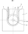
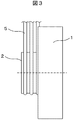
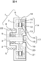
図1〜図4は、本発明の実施例を示すものであり、図1は正面図、図2は平面図、図3は側面図、図4は中心軸視点の断面側面図である。本実施例は、主に巻上機の筐体1、綱車2、主軸3、軸受9、回転子14、固定子17、ブレーキドラム18、ロータリーエンコーダ19、エンコーダ軸20、エンコーダ支持板21から構成される。
1 to 4 show an embodiment of the present invention. FIG. 1 is a front view, FIG. 2 is a plan view, FIG. 3 is a side view, and FIG. This embodiment mainly consists of a casing 1 of a hoisting machine, a
筐体1は、主に脚部6と軸受支持部8、そして脚部6と軸受支持部8を接続する側壁7で構成されており、例えば鋳造で一体成形される。軸受支持部8の内部には軸受9を内臓し、軸受9により主軸3を回転自在に支持する。主軸3の一端には綱車2が固定され、他端には回転子14が固定される。主軸3は回転軸であり、綱車2、回転子14と一体になって回転する。
The housing 1 is mainly composed of a
回転子14は、主に回転子ヨーク10と永久磁石11、回転子固定部13、および回転子ヨーク10と回転子固定部13をつなぐ接続部12から構成されている。永久磁石11は回転子ヨーク10の内側に貼付けられ(表面磁石式)、回転子ヨーク10、接続部12および固定部13は、例えば鋳造で一体成形される。回転子ヨーク10および永久磁石11の内側に対向する位置には固定子17を配置し、アウターロータモータを構成する。固定子17は主に固定子鉄心15と固定子巻線16から構成され、固定子巻線16は集中巻とする。また固定子17は筐体1に固定される。
The
回転子ヨーク10の外周面は滑らかな円筒平面とし、巻上機のブレーキドラム18を兼用する。図示されてないが、巻上機のブレーキ制動装置を筐体1の外側に取付け、ブレーキドラム18を外側から制動する構造となっている。
The outer peripheral surface of the
主軸3の綱車2と対向する他端部には、主軸3と一体となって回転するエンコーダ軸20が取付けられ、エンコーダ軸20の回転を検知するために、ロータリーエンコーダ19が筐体1に取付けられたエンコーダ支持板21によって固定されている。
An
綱車2の外周には複数(実施例では3個)の溝が加工されており、それぞれの溝にはエレベータの昇降駆動用のロープ5が巻き掛けられる。ロープ5はエレベータの乗りかごや釣合い錘などのエレベータ機器を支持しており、綱車2にはそれらのエレベータ機器を懸垂するための支持力が作用する。この支持力は主軸3および軸受9を介して筐体1で支持される。具体的には筐体1の軸受支持部8、筐体側壁7を介して、筐体の脚部6で支持される。
A plurality of (three in the embodiment) grooves are machined on the outer periphery of the
また、主に回転子14と固定子17から成るモータ部で発生する回転力は、主軸3を介して綱車2に伝達し、綱車2に巻き掛けられたロープ5を駆動することで、エレベータ乗りかごや釣合い錘などのエレベータ機器を昇降させる。
In addition, the rotational force generated in the motor unit mainly composed of the
上記構成において、筐体1の側壁7の外側(側壁7の上記綱車2側)には凹状の溝4が、ロープの巻き掛け方向と同じ向きに設けられており、綱車2に巻き掛けられたロープ5の一部は溝4を通過する構成となっている。
In the above configuration, a concave groove 4 is provided on the outside of the
本実施例の側壁7は固定壁であるので、側壁7に設けられた溝4にロープを通すことが可能であり、綱車2および回転子14が回転しても、ロープ5と溝4(側壁7)が干渉することは無い。なお本実施例ではロープの巻き掛け角度を180°で図示しているが、180°に限るものではなく、180°超または180°未満でも良い。この場合、ロープの巻き掛け角度に応じて、ロープ5と溝4が干渉することが無いように、溝4の角度や幅が調整される。
Since the
ロープ5の一部を溝4に通すため、綱車2を筐体1の側壁7側に寄せて配置する必要があり、これによって巻上機の薄型化が達成されるものである。綱車2を筐体1の側に寄せて配置するためには、綱車2の一部が筐体1の内部に入り込むように配置しなくてはならない。本実施例では綱車2の一部が筐体1の側壁7の内部に入り込めるように、筐体1の側壁7の上記綱車2側に、上記溝4に連通した環状の凹み22が設けられ、入り子構造としている。
In order to pass a part of the
本実施例での上記各要素は、エレベータ用巻上機を構成しているが、同時に綱車2を備えた駆動モータをも構成している。この場合、駆動モータは、エレベータの懸垂荷重を支持する筐体1と、上記筐体内に設置された軸受9によって回転自在に支持された主軸3と、上記主軸に接合された綱車2と、上記主軸に接合された回転子14と、上記回転子に対向して配置される固定子17を構成要件とし、回転子ヨーク10および永久磁石11の内側に対向する位置には固定子17を配置して、アウターロータモータを構成している。
Although each said element in a present Example comprises the hoisting machine for elevators, the drive motor provided with the
本実施例では、上記のようにアウターロータモータで構成されているが、回転子14が外側配置であるため半径を大きくとることができ、大きなトルクが得られる。
In this embodiment, the outer rotor motor is used as described above. However, since the
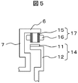
また、他の実施例としてモータ部をインナロータモータで構成しても良い。この場合、図5に示すように回転子14が内側で、固定子17が外側に配置されるのみで、その他の構造には大きな変更点は無く、本発明の主旨である筐体側壁7に溝4や環状凹部22を設けて、そこにロープ5や綱車2を入り込ませる構造は何ら変わらない。ただしブレーキ制動用のドラムを固定子の外側に別途設けるか、インナロータの内周面を制動するブレーキ構造に変更する必要がある。図5で、図4と同一部分を同一符号で示す。
In another embodiment, the motor unit may be an inner rotor motor. In this case, as shown in FIG. 5, only the
1…筐体、2…綱車、3…主軸、4…溝、5…ロープ、6…筐体を構成する脚部、7…筐体を構成する側壁、8…筐体を構成する軸受支持部、9…軸受、10…回転子ヨーク、11…永久磁石、12…回転子ヨークと回転子支持部を接続する接続部、13…回転子の支持部、14…回転子、15…固定子鉄心、16…固定子巻線、17…固定子、18…ブレーキドラム、19…ロータリーエンコーダ、20…エンコーダ軸、21…ロータリーエンコーダ支持板、22…環状の凹み。
DESCRIPTION OF SYMBOLS 1 ... Housing, 2 ... Sheave, 3 ... Main shaft, 4 ... Groove, 5 ... Rope, 6 ... Leg part which comprises housing | casing, 7 ... Side wall which comprises housing | casing, 8 ... Bearing support which comprises housing | casing
Claims (12)
上記筐体は上記軸受が設置された側壁を有し、
上記綱車と上記モータの回転子とはこの側壁を挟むように上記主軸の両端に固定され、
上記側壁は上記綱車側に設けられた凹状の溝を有し、
上記回転子の回転力が上記主軸を介して上記綱車に伝達されるに際し、上記綱車に巻き掛けられたロープが上記溝を通過するように構成されたことを特徴とするエレベータ用巻上機。 A housing for supporting the suspension load of the elevator, a main shaft rotatably supported by a bearing installed in the housing, a sheave joined to the main shaft, and a rotor of a motor joined to the main shaft; In a hoisting machine having a stator of a motor arranged to face the rotor,
The housing has a side wall on which the bearing is installed,
The sheave and the rotor of the motor are fixed to both ends of the main shaft so as to sandwich the side wall,
The side wall has a concave groove provided on the sheave side,
The elevator hoisting machine is configured such that when the rotational force of the rotor is transmitted to the sheave via the main shaft, a rope wound around the sheave passes through the groove. Machine.
上記筐体は上記軸受が設置された側壁を有し、
上記綱車と上記回転子とはこの側壁を挟むように上記主軸の両端に固定され、
上記側壁は上記綱車側に設けられた凹状の溝を有し、
上記回転子の回転力が上記主軸を介して上記綱車に伝達されるに際し、上記綱車に巻き掛けられたロープが上記溝を通過するように構成されたことを特徴とするエレベータ用巻上機の駆動モータ。 A housing that supports the suspension load of the elevator, a main shaft that is rotatably supported by a bearing installed in the housing, a sheave joined to the main shaft, a rotor joined to the main shaft, and the above In the drive motor of an elevator hoisting machine having a stator arranged opposite to the rotor,
The housing has a side wall on which the bearing is installed,
The sheave and the rotor are fixed to both ends of the main shaft so as to sandwich the side wall,
The side wall has a concave groove provided on the sheave side,
The elevator hoisting machine is configured such that when the rotational force of the rotor is transmitted to the sheave via the main shaft, a rope wound around the sheave passes through the groove. Machine drive motor.
Priority Applications (1)
| Application Number | Priority Date | Filing Date | Title |
|---|---|---|---|
| JP2008319865A JP5238473B2 (en) | 2008-12-16 | 2008-12-16 | Elevator hoisting machine and its drive motor |
Applications Claiming Priority (1)
| Application Number | Priority Date | Filing Date | Title |
|---|---|---|---|
| JP2008319865A JP5238473B2 (en) | 2008-12-16 | 2008-12-16 | Elevator hoisting machine and its drive motor |
Publications (2)
| Publication Number | Publication Date |
|---|---|
| JP2010143661A true JP2010143661A (en) | 2010-07-01 |
| JP5238473B2 JP5238473B2 (en) | 2013-07-17 |
Family
ID=42564496
Family Applications (1)
| Application Number | Title | Priority Date | Filing Date |
|---|---|---|---|
| JP2008319865A Expired - Fee Related JP5238473B2 (en) | 2008-12-16 | 2008-12-16 | Elevator hoisting machine and its drive motor |
Country Status (1)
| Country | Link |
|---|---|
| JP (1) | JP5238473B2 (en) |
Cited By (4)
| Publication number | Priority date | Publication date | Assignee | Title |
|---|---|---|---|---|
| WO2017022097A1 (en) * | 2015-08-05 | 2017-02-09 | 三菱電機株式会社 | Inner-rotor type hoist |
| CN108689283A (en) * | 2017-04-07 | 2018-10-23 | 株式会社日立制作所 | Traction machine and elevator |
| WO2019008761A1 (en) * | 2017-07-07 | 2019-01-10 | 三菱電機株式会社 | Elevator hoist |
| KR102187699B1 (en) * | 2020-08-25 | 2020-12-07 | 주식회사 비티알수성 | Structure for installing encoder of driver for elevator |
Citations (1)
| Publication number | Priority date | Publication date | Assignee | Title |
|---|---|---|---|---|
| JP2006089225A (en) * | 2004-09-24 | 2006-04-06 | Matsushita Electric Ind Co Ltd | Elevator apparatus |
-
2008
- 2008-12-16 JP JP2008319865A patent/JP5238473B2/en not_active Expired - Fee Related
Patent Citations (1)
| Publication number | Priority date | Publication date | Assignee | Title |
|---|---|---|---|---|
| JP2006089225A (en) * | 2004-09-24 | 2006-04-06 | Matsushita Electric Ind Co Ltd | Elevator apparatus |
Cited By (6)
| Publication number | Priority date | Publication date | Assignee | Title |
|---|---|---|---|---|
| WO2017022097A1 (en) * | 2015-08-05 | 2017-02-09 | 三菱電機株式会社 | Inner-rotor type hoist |
| CN108689283A (en) * | 2017-04-07 | 2018-10-23 | 株式会社日立制作所 | Traction machine and elevator |
| WO2019008761A1 (en) * | 2017-07-07 | 2019-01-10 | 三菱電機株式会社 | Elevator hoist |
| JPWO2019008761A1 (en) * | 2017-07-07 | 2019-11-07 | 三菱電機株式会社 | Elevator hoisting machine |
| CN110831884A (en) * | 2017-07-07 | 2020-02-21 | 三菱电机株式会社 | Traction machine for elevator |
| KR102187699B1 (en) * | 2020-08-25 | 2020-12-07 | 주식회사 비티알수성 | Structure for installing encoder of driver for elevator |
Also Published As
| Publication number | Publication date |
|---|---|
| JP5238473B2 (en) | 2013-07-17 |
Similar Documents
| Publication | Publication Date | Title |
|---|---|---|
| JP5070912B2 (en) | Elevator hoisting machine | |
| JP2010235266A (en) | Thin type hoisting machine and driving motor for thin type hoisting machine | |
| JP2016037336A (en) | Elevator device and hoist for elevator device | |
| JP5238473B2 (en) | Elevator hoisting machine and its drive motor | |
| JPWO2005080251A1 (en) | Elevator hoisting machine | |
| JP5216797B2 (en) | Hoisting machine | |
| JP5809531B2 (en) | Elevator thin hoist | |
| JP2004338915A (en) | Hoisting machine for elevator | |
| JP5048802B2 (en) | Thin hoisting machine for elevator and elevator device | |
| KR100691663B1 (en) | Driver of elevator | |
| JP5032723B2 (en) | Elevator hoisting machine | |
| JP5591767B2 (en) | Thin hoisting machine and elevator equipment | |
| JP2013040033A (en) | Hoisting machine for elevator | |
| JP4677409B2 (en) | Elevator equipment | |
| JPWO2005068338A1 (en) | Elevator hoisting machine | |
| JP2011201671A5 (en) | ||
| JP2005247514A (en) | Hoisting machine for elevator | |
| JP4475017B2 (en) | Elevator hoisting machine | |
| JP4522181B2 (en) | Elevator hoisting machine | |
| JPWO2004000711A1 (en) | Elevator equipment | |
| JP2013245076A (en) | Elevator device | |
| JP5358282B2 (en) | Elevator hoisting machine and elevator device | |
| JP5590471B2 (en) | Hoisting machine and elevator | |
| KR100343982B1 (en) | Traction machine for elevator | |
| KR20070105289A (en) | Traction device for elevator |
Legal Events
| Date | Code | Title | Description |
|---|---|---|---|
| A621 | Written request for application examination |
Free format text: JAPANESE INTERMEDIATE CODE: A621 Effective date: 20110316 |
|
| A711 | Notification of change in applicant |
Free format text: JAPANESE INTERMEDIATE CODE: A711 Effective date: 20110916 |
|
| A131 | Notification of reasons for refusal |
Free format text: JAPANESE INTERMEDIATE CODE: A131 Effective date: 20120807 |
|
| A977 | Report on retrieval |
Free format text: JAPANESE INTERMEDIATE CODE: A971007 Effective date: 20120809 |
|
| A521 | Request for written amendment filed |
Free format text: JAPANESE INTERMEDIATE CODE: A523 Effective date: 20120919 |
|
| TRDD | Decision of grant or rejection written | ||
| A01 | Written decision to grant a patent or to grant a registration (utility model) |
Free format text: JAPANESE INTERMEDIATE CODE: A01 Effective date: 20130312 |
|
| A61 | First payment of annual fees (during grant procedure) |
Free format text: JAPANESE INTERMEDIATE CODE: A61 Effective date: 20130401 |
|
| R150 | Certificate of patent or registration of utility model |
Free format text: JAPANESE INTERMEDIATE CODE: R150 Ref document number: 5238473 Country of ref document: JP Free format text: JAPANESE INTERMEDIATE CODE: R150 |
|
| FPAY | Renewal fee payment (event date is renewal date of database) |
Free format text: PAYMENT UNTIL: 20160405 Year of fee payment: 3 |
|
| LAPS | Cancellation because of no payment of annual fees |