JP2010142831A - Method and device for cleaning upper/lower punches in powder compacting press machine - Google Patents
Method and device for cleaning upper/lower punches in powder compacting press machine Download PDFInfo
- Publication number
- JP2010142831A JP2010142831A JP2008321383A JP2008321383A JP2010142831A JP 2010142831 A JP2010142831 A JP 2010142831A JP 2008321383 A JP2008321383 A JP 2008321383A JP 2008321383 A JP2008321383 A JP 2008321383A JP 2010142831 A JP2010142831 A JP 2010142831A
- Authority
- JP
- Japan
- Prior art keywords
- punch
- brush
- powder
- punches
- die
- Prior art date
- Legal status (The legal status is an assumption and is not a legal conclusion. Google has not performed a legal analysis and makes no representation as to the accuracy of the status listed.)
- Ceased
Links
- 239000000843 powder Substances 0.000 title claims abstract description 41
- 238000004140 cleaning Methods 0.000 title claims abstract description 23
- 238000000034 method Methods 0.000 title claims abstract description 10
- 239000013067 intermediate product Substances 0.000 claims description 13
- 238000000465 moulding Methods 0.000 claims description 13
- 239000002184 metal Substances 0.000 description 5
- 229910052751 metal Inorganic materials 0.000 description 5
- 239000000919 ceramic Substances 0.000 description 2
- 238000000748 compression moulding Methods 0.000 description 2
- 238000010304 firing Methods 0.000 description 2
- 239000011347 resin Substances 0.000 description 2
- 229920005989 resin Polymers 0.000 description 2
- 239000011230 binding agent Substances 0.000 description 1
- 230000006835 compression Effects 0.000 description 1
- 238000007906 compression Methods 0.000 description 1
- 238000010586 diagram Methods 0.000 description 1
- 239000000428 dust Substances 0.000 description 1
- 230000000694 effects Effects 0.000 description 1
- 238000003754 machining Methods 0.000 description 1
- 238000004519 manufacturing process Methods 0.000 description 1
- 150000002739 metals Chemical class 0.000 description 1
- 238000007790 scraping Methods 0.000 description 1
- 238000007493 shaping process Methods 0.000 description 1
Images


Landscapes
- Cleaning In General (AREA)
Abstract
Description
本発明は、金属、セラミックス等の微粉末を圧縮成形して焼成し、超硬チップや精密機械部品等を製造する際の前半工程である粉末の圧縮成形において、上下パンチに付着する粉末を除去して清浄にする粉末成形プレス機の上下パンチの清掃方法およびその装置に関する。 The present invention removes the powder adhering to the upper and lower punches in compression molding of powder, which is the first half of the process when producing cemented carbide chips, precision machine parts, etc., by compacting and firing fine powders of metals, ceramics, etc. The present invention relates to a cleaning method and apparatus for upper and lower punches of a powder molding press machine to be cleaned.
金属、セラミックス等の微粉末にワックス等のバインダを混合してプレス機の金型内に充填し、圧縮成形して中間製品を製造し、これを焼成炉において焼成処理して機械加工用の超硬チップや精密機械部品等を製造することが行われている。圧縮成形に使用する金型は一般に加熱を行うので、充填の際周囲に微粉末が付着しやすく、中間製品に付着するなどして品質上問題となるため、上下パンチなどの金型を清掃することが必要である。 A binder such as wax is mixed with fine powders of metal, ceramics, etc., filled in a press mold, compression molded to produce an intermediate product, which is fired in a firing furnace to be used for machining. Manufacturing hard chips, precision machine parts, and the like has been carried out. Molds used for compression molding are generally heated, so fine powder tends to adhere to the surroundings during filling, which can cause quality problems such as adhesion to intermediate products. Clean molds such as upper and lower punches. It is necessary.
金型の清掃は樹脂等のブラシで付着した微粉末をこすり落とすのであるが、この作業を人手によって行っていたのでは金型の寸法が小さい場合などに作業が困難であり、また生産性を阻害するから、機械化することが必要である。特許文献1には、回転ブラシ方式の粉末成形プレス機の金型清掃装置が記載されている。
特許文献1に記載の金型清掃装置は円盤状のブラシを回転させながら金型を清掃するので、金型の形状如何によらず使用できる利点はあるが、金型が直線形状だったり、さらにこれが複数列並んだりしている場合には清掃効率がよくないという問題点がある。
本発明は、上下パンチの平面形状が直線状で、かつそれが複数列並んだりしている場合に好適な粉末成形プレス機の上下パンチの清掃方法およびその装置を提供することを目的とする。
Since the mold cleaning apparatus described in
An object of the present invention is to provide a cleaning method and apparatus for an upper and lower punch of a powder molding press suitable for a case where the planar shape of the upper and lower punches is a straight line and a plurality of rows are arranged.
請求項1に記載の本発明は、ダイの上下に直線形状の上パンチ、下パンチを複数列配置し、下パンチとダイとで形成される空間内に粉末を充填し、上から上パンチを下降させてこの粉末を圧縮、成形して中間製品を得る粉末成形プレス機において、前記中間製品を取り出した後、上パンチ、下パンチが開いた状態においてこれらの中間に上下方向にブラシを備えたパンチクリーナを挿入し、このパンチクリーナを上昇させるか、あるいは上パンチを下降させ、ブラシを上パンチに接触させたまま振動および/または水平移動させて上パンチ下面に付着した粉末を除去し、前記パンチクリーナを下降させるか、あるいは下パンチを上昇させ、ブラシを下パンチに接触させたまま振動および/または水平移動させて下パンチ上面に付着した粉末を除去することを特徴とする粉末成形プレス機の上下パンチの清掃方法である。 According to the first aspect of the present invention, a plurality of rows of linear upper punches and lower punches are arranged above and below the die, powder is filled in a space formed by the lower punch and the die, and the upper punches are arranged from above. In a powder molding press that obtains an intermediate product by lowering and compressing and molding this powder, after taking out the intermediate product, the upper punch and the lower punch were opened with a brush in the vertical direction between them. Insert a punch cleaner, raise the punch cleaner, or lower the upper punch, and vibrate and / or move horizontally with the brush in contact with the upper punch to remove the powder adhering to the lower surface of the upper punch, Lower the punch cleaner, or raise the lower punch, and vibrate and / or move horizontally while keeping the brush in contact with the lower punch. A cleaning method of the upper and lower punches of the powder molding press, characterized by removed by.
請求項2に記載の本発明は、前記ブラシ近傍に気体を噴射して、除去した粉末を吹き飛ばすようにした請求項1に記載の粉末成形プレス機の上下パンチの清掃方法である。
請求項3に記載の本発明は、ダイの上下に直線形状の上パンチ、下パンチを複数列配置し、下パンチとダイとで形成される空間内に粉末を充填し、上から上パンチを下降させてこの粉末を圧縮、成形して中間製品を得る粉末成形プレス機において、上下方向にブラシを備え、前記上パンチと下パンチとの中間に挿入可能でかつ、前記上パンチまたは下パンチに対してブラシを接触させるため昇降可能であり、前記ブラシが振動および/または水平移動可能であることを特徴とする粉末成形プレス機の上下パンチの清掃装置である。
The present invention described in
According to the third aspect of the present invention, a plurality of lines of linear upper punches and lower punches are arranged above and below the die, the powder formed in the space formed by the lower punch and the die, In a powder forming press that obtains an intermediate product by lowering and compressing this powder, a brush is provided in the vertical direction and can be inserted between the upper punch and the lower punch, and can be inserted into the upper punch or the lower punch. An apparatus for cleaning the upper and lower punches of a powder molding press machine, wherein the brush can be moved up and down to contact the brush, and the brush can vibrate and / or move horizontally.
請求項4に記載の本発明は、前記ブラシが金型に対して斜め方向に向いている請求項3に記載の粉末成形プレス機の上下パンチの清掃装置である。
The present invention described in
本発明によれば、金型の平面形状が直線状で、かつそれが複数列並んでいる場合においても効率よく清掃を行うことができ、生産性が向上するという、すぐれた効果を奏する。 ADVANTAGE OF THE INVENTION According to this invention, even when the planar shape of a metal mold | die is linear, and it is located in multiple rows, it can clean efficiently and there exists an outstanding effect that productivity improves.
本発明の実施例を図面により説明する。まず、図1により、本発明に係わる粉末成形プレス機の作動を説明する。図1において1はプレス機のダイ(臼)、2は上パンチ、3は下パンチで、上パンチ、下パンチはダイ1の上下に配置され、(a)に示すように下パンチ3とダイ1とで形成される空間内に粉末Pが充填される。つぎに(b)に示すように上パンチ2が下降して粉末を圧縮し、中間製品Gができる。つづいて中間製品Gを保持したままダイ1を下降させるか、(c)に示すように上パンチ2および下パンチ3を上昇させて、中間製品Gをダイ1の上部に上げ、(d)に示すように上パンチ2をさらに上昇させて中間製品Gを取り出す。その後、この状態で上パンチ2および下パンチ3の中間にパンチクリーナ4を挿入する。
Embodiments of the present invention will be described with reference to the drawings. First, the operation of the powder forming press according to the present invention will be described with reference to FIG. In FIG. 1, 1 is a die (mill) of a press machine, 2 is an upper punch, 3 is a lower punch, and an upper punch and a lower punch are arranged above and below the
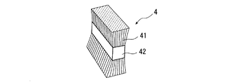
図2はパンチクリーナ4のブラシ部分の斜視図で、41は樹脂等のブラシ、42はこれを束ねて保持するブラシホルダでえある。
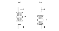
パンチクリーナ4を挿入したら、図3(a)に示すようにパンチクリーナ4を上昇させるか、あるいは上パンチ2を下降させ、上側のブラシ41を上パンチ2に接触させ、上パンチ2の下面に付着した粉末を清掃、除去する。つづいて図3(b)に示すようにパンチクリーナ4を下降させるか、あるいは下パンチ3を上昇させ、下側のブラシ41を下パンチ3に接触させ、下パンチ3の上面に付着した粉末を清掃、除去する。
FIG. 2 is a perspective view of the brush portion of the
When the
図4は実施例の金型とブラシの関係を示す平面図で、金型を上パンチ2で代表させている。2a〜2dは直線形状の金型で、4列並んで配置されている。一方4a〜4cはパンチクリーナで、金型に対して斜めに、3列並んで配置されている。清掃、作業はブラシ4a〜4cを振動させ、かつ矢印のように水平移動させて行う。振動はブラシホルダ全体をモータにより偏心機構等を利用して行えばよいが、振動機構は特に限定しない。振動のみ、あるいは水平移動のみでもある程度の清掃はできる。ここで図4に示すように金型の直線方向に対してブラシが斜めになっていると、水平移動に伴ってブラシの接触位置が連続的に変化して、まんべんなく清掃ができる。
FIG. 4 is a plan view showing the relationship between the mold and the brush in the embodiment, and the mold is represented by the
なお、上下パンチはそれぞれ昇降可能であるから、パンチクリーナの高さを一定にしてパンチの昇降で上記の清掃を行ってもよいのであるが、プレス機によっては上下パンチの動きが連動している場合が多く、上下パンチそれぞれを独立に昇降させることが困難であれば、パンチクリーナを昇降させる方が現実的である。この場合、上下パンチを同時に清掃することはできないから、上下順番に行うことになる。 Since the upper and lower punches can be raised and lowered, the above-mentioned cleaning may be performed by raising and lowering the punch with the height of the punch cleaner constant. In many cases, if it is difficult to raise and lower each of the upper and lower punches independently, it is more realistic to raise and lower the punch cleaner. In this case, since the upper and lower punches cannot be cleaned at the same time, they are performed in the vertical order.
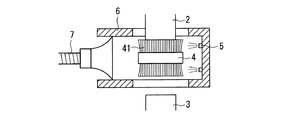
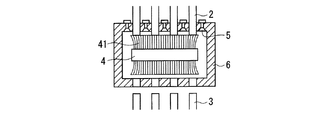
図5は、周辺を含めたパンチクリーナのプレス機側面から見た水平方向断面図、図6は同じくプレス機正面から見た水平方向断面図で、符号5はエア等の気体の噴出するノズル、
6はパンチクリーナを囲むケーシング、7は吸引ダクトである。
ケーシング6の上下面には上下パンチが出入するスリットが設けられており、清掃中は上下パンチはこのスリットを通ってケーシング内のブラシと接触する。清掃中に発生する粉塵はノズル5による気流に乗って吹き飛ばされ、吸引ダクト7を経て排出される。ノズル5はケーシング6の先端部や上下スリットの両脇などに配置されている。
FIG. 5 is a horizontal sectional view seen from the side of the press of the punch cleaner including the periphery, FIG. 6 is a horizontal sectional view similarly seen from the front of the press, and
6 is a casing surrounding the punch cleaner, and 7 is a suction duct.
The upper and lower surfaces of the
1 ダイ
2 上パンチ(金型)
3 下パンチ(金型)
4 パンチクリーナ
5 ノズル
6 ケーシング
7 吸引ダクト
41 ブラシ
42 ブラシホルダ
G 中間製品
P 粉末
1 die 2 top punch (die)
3 Lower punch (die)
4
Claims (4)
Priority Applications (1)
| Application Number | Priority Date | Filing Date | Title |
|---|---|---|---|
| JP2008321383A JP2010142831A (en) | 2008-12-17 | 2008-12-17 | Method and device for cleaning upper/lower punches in powder compacting press machine |
Applications Claiming Priority (1)
| Application Number | Priority Date | Filing Date | Title |
|---|---|---|---|
| JP2008321383A JP2010142831A (en) | 2008-12-17 | 2008-12-17 | Method and device for cleaning upper/lower punches in powder compacting press machine |
Publications (1)
| Publication Number | Publication Date |
|---|---|
| JP2010142831A true JP2010142831A (en) | 2010-07-01 |
Family
ID=42563805
Family Applications (1)
| Application Number | Title | Priority Date | Filing Date |
|---|---|---|---|
| JP2008321383A Ceased JP2010142831A (en) | 2008-12-17 | 2008-12-17 | Method and device for cleaning upper/lower punches in powder compacting press machine |
Country Status (1)
| Country | Link |
|---|---|
| JP (1) | JP2010142831A (en) |
Cited By (1)
| Publication number | Priority date | Publication date | Assignee | Title |
|---|---|---|---|---|
| DE102022115278A1 (en) | 2022-06-20 | 2023-12-21 | Dorst Technologies Gmbh & Co. Kg | Device for cleaning a powder press device, combination of a powder press device with such a cleaning device and method for cleaning a powder press device |
Citations (7)
| Publication number | Priority date | Publication date | Assignee | Title |
|---|---|---|---|---|
| GB134102A (en) * | 1918-12-13 | 1919-10-30 | Const S A C D A Schmid Atel | Improvements in or relating to Presses for Moulding Powdered Materials. |
| JP2000141097A (en) * | 1998-11-12 | 2000-05-23 | Konica Corp | Method for compression forming of tablet and device therefor |
| JP2000202386A (en) * | 1999-01-20 | 2000-07-25 | Ooyodo Diesel Kk | Duct cleaning method and device |
| JP2002331397A (en) * | 2001-05-07 | 2002-11-19 | Sanwa System Engineering Kk | Mold cleaning device of powder molding press |
| JP2003001497A (en) * | 2001-06-20 | 2003-01-08 | Sekitekku:Kk | Mold cleaning device for powder molding press |
| JP2003275899A (en) * | 2002-03-20 | 2003-09-30 | Totan Kako Kk | Forming apparatus of granular body, forming method of granular body using the forming apparatus and formed body obtained by the forming method |
| JP2008012914A (en) * | 2006-07-07 | 2008-01-24 | Ibiden Co Ltd | End face processing apparatus, end face processing method for honeycomb formed body, and manufacturing method for honeycomb structure |
-
2008
- 2008-12-17 JP JP2008321383A patent/JP2010142831A/en not_active Ceased
Patent Citations (7)
| Publication number | Priority date | Publication date | Assignee | Title |
|---|---|---|---|---|
| GB134102A (en) * | 1918-12-13 | 1919-10-30 | Const S A C D A Schmid Atel | Improvements in or relating to Presses for Moulding Powdered Materials. |
| JP2000141097A (en) * | 1998-11-12 | 2000-05-23 | Konica Corp | Method for compression forming of tablet and device therefor |
| JP2000202386A (en) * | 1999-01-20 | 2000-07-25 | Ooyodo Diesel Kk | Duct cleaning method and device |
| JP2002331397A (en) * | 2001-05-07 | 2002-11-19 | Sanwa System Engineering Kk | Mold cleaning device of powder molding press |
| JP2003001497A (en) * | 2001-06-20 | 2003-01-08 | Sekitekku:Kk | Mold cleaning device for powder molding press |
| JP2003275899A (en) * | 2002-03-20 | 2003-09-30 | Totan Kako Kk | Forming apparatus of granular body, forming method of granular body using the forming apparatus and formed body obtained by the forming method |
| JP2008012914A (en) * | 2006-07-07 | 2008-01-24 | Ibiden Co Ltd | End face processing apparatus, end face processing method for honeycomb formed body, and manufacturing method for honeycomb structure |
Cited By (1)
| Publication number | Priority date | Publication date | Assignee | Title |
|---|---|---|---|---|
| DE102022115278A1 (en) | 2022-06-20 | 2023-12-21 | Dorst Technologies Gmbh & Co. Kg | Device for cleaning a powder press device, combination of a powder press device with such a cleaning device and method for cleaning a powder press device |
Similar Documents
| Publication | Publication Date | Title |
|---|---|---|
| US10124374B2 (en) | Board cleaning apparatus | |
| JP5403403B2 (en) | Casting line and sand removal method | |
| CN111451499A (en) | Selective laser melting forming method for parts containing internal cavities | |
| CN104029279B (en) | Brickmaking device and method for quick forming of special-shaped bricks | |
| CN110614727B (en) | Automatic fine engraving machine and fine engraving process thereof | |
| CN207825308U (en) | A kind of board mould cleaning plant | |
| CN117960817A (en) | Extrusion equipment for forging tooth holder and forming method | |
| JP2016221875A (en) | 3D modeling equipment | |
| JP2010142831A (en) | Method and device for cleaning upper/lower punches in powder compacting press machine | |
| CN103302057A (en) | Automatic dust removing and collecting machine | |
| JP5592711B2 (en) | Deburring device for powder molded products | |
| KR102141814B1 (en) | Hard-metal insert cleaning device | |
| CN106903273B (en) | Manipulator for sand core of brake disc | |
| CN205798130U (en) | A stamping die with automatic waste discharge | |
| CN108943712B (en) | 3D printing system capable of working continuously | |
| CN213378789U (en) | Dust removal structure for automobile part stamping die | |
| CN113522812B (en) | A plastic mold processing equipment | |
| JP4410396B2 (en) | Mold cleaning method and cleaning device | |
| CN117840332A (en) | Hardware die convenient to clean | |
| JPH03234603A (en) | Surface-cleaning device for powder-formed object | |
| CN212445756U (en) | A kind of electronic ceramic sheet automatic forming equipment | |
| CN206622578U (en) | Brake disc core manipulator | |
| CN207888427U (en) | A kind of piezoelectricity burr remover | |
| CN216150475U (en) | Upper and lower die device of automatic cleaning press after hard alloy molding | |
| JP5493141B2 (en) | Deburring method and apparatus for powder molded parts |
Legal Events
| Date | Code | Title | Description |
|---|---|---|---|
| A521 | Written amendment |
Free format text: JAPANESE INTERMEDIATE CODE: A523 Effective date: 20110801 |
|
| A711 | Notification of change in applicant |
Free format text: JAPANESE INTERMEDIATE CODE: A711 Effective date: 20110802 |
|
| A521 | Written amendment |
Free format text: JAPANESE INTERMEDIATE CODE: A821 Effective date: 20110801 |
|
| A521 | Written amendment |
Free format text: JAPANESE INTERMEDIATE CODE: A821 Effective date: 20110802 |
|
| A621 | Written request for application examination |
Free format text: JAPANESE INTERMEDIATE CODE: A621 Effective date: 20111216 |
|
| A131 | Notification of reasons for refusal |
Free format text: JAPANESE INTERMEDIATE CODE: A131 Effective date: 20130604 |
|
| A521 | Written amendment |
Free format text: JAPANESE INTERMEDIATE CODE: A523 Effective date: 20130801 |
|
| RD02 | Notification of acceptance of power of attorney |
Free format text: JAPANESE INTERMEDIATE CODE: A7422 Effective date: 20130801 |
|
| RD04 | Notification of resignation of power of attorney |
Free format text: JAPANESE INTERMEDIATE CODE: A7424 Effective date: 20130821 |
|
| A01 | Written decision to grant a patent or to grant a registration (utility model) |
Free format text: JAPANESE INTERMEDIATE CODE: A01 Effective date: 20140225 |
|
| A045 | Written measure of dismissal of application |
Free format text: JAPANESE INTERMEDIATE CODE: A045 Effective date: 20140624 |