JP2010108321A - Construction progress visualization system - Google Patents
Construction progress visualization system Download PDFInfo
- Publication number
- JP2010108321A JP2010108321A JP2008280670A JP2008280670A JP2010108321A JP 2010108321 A JP2010108321 A JP 2010108321A JP 2008280670 A JP2008280670 A JP 2008280670A JP 2008280670 A JP2008280670 A JP 2008280670A JP 2010108321 A JP2010108321 A JP 2010108321A
- Authority
- JP
- Japan
- Prior art keywords
- scaffold
- construction
- work
- cad model
- mesh
- Prior art date
- Legal status (The legal status is an assumption and is not a legal conclusion. Google has not performed a legal analysis and makes no representation as to the accuracy of the status listed.)
- Pending
Links
Images


Classifications
-
- G—PHYSICS
- G06—COMPUTING OR CALCULATING; COUNTING
- G06Q—INFORMATION AND COMMUNICATION TECHNOLOGY [ICT] SPECIALLY ADAPTED FOR ADMINISTRATIVE, COMMERCIAL, FINANCIAL, MANAGERIAL OR SUPERVISORY PURPOSES; SYSTEMS OR METHODS SPECIALLY ADAPTED FOR ADMINISTRATIVE, COMMERCIAL, FINANCIAL, MANAGERIAL OR SUPERVISORY PURPOSES, NOT OTHERWISE PROVIDED FOR
- G06Q50/00—Information and communication technology [ICT] specially adapted for implementation of business processes of specific business sectors, e.g. utilities or tourism
- G06Q50/08—Construction
-
- G—PHYSICS
- G06—COMPUTING OR CALCULATING; COUNTING
- G06F—ELECTRIC DIGITAL DATA PROCESSING
- G06F30/00—Computer-aided design [CAD]
- G06F30/10—Geometric CAD
- G06F30/13—Architectural design, e.g. computer-aided architectural design [CAAD] related to design of buildings, bridges, landscapes, production plants or roads
-
- G—PHYSICS
- G06—COMPUTING OR CALCULATING; COUNTING
- G06Q—INFORMATION AND COMMUNICATION TECHNOLOGY [ICT] SPECIALLY ADAPTED FOR ADMINISTRATIVE, COMMERCIAL, FINANCIAL, MANAGERIAL OR SUPERVISORY PURPOSES; SYSTEMS OR METHODS SPECIALLY ADAPTED FOR ADMINISTRATIVE, COMMERCIAL, FINANCIAL, MANAGERIAL OR SUPERVISORY PURPOSES, NOT OTHERWISE PROVIDED FOR
- G06Q10/00—Administration; Management
- G06Q10/06—Resources, workflows, human or project management; Enterprise or organisation planning; Enterprise or organisation modelling
- G06Q10/063—Operations research, analysis or management
- G06Q10/0631—Resource planning, allocation, distributing or scheduling for enterprises or organisations
Landscapes
- Engineering & Computer Science (AREA)
- Business, Economics & Management (AREA)
- Physics & Mathematics (AREA)
- Human Resources & Organizations (AREA)
- Theoretical Computer Science (AREA)
- Strategic Management (AREA)
- Economics (AREA)
- General Physics & Mathematics (AREA)
- Entrepreneurship & Innovation (AREA)
- General Business, Economics & Management (AREA)
- Geometry (AREA)
- Tourism & Hospitality (AREA)
- Marketing (AREA)
- Development Economics (AREA)
- Educational Administration (AREA)
- Quality & Reliability (AREA)
- Operations Research (AREA)
- Game Theory and Decision Science (AREA)
- Computer Hardware Design (AREA)
- Mathematical Optimization (AREA)
- Evolutionary Computation (AREA)
- Primary Health Care (AREA)
- General Health & Medical Sciences (AREA)
- Pure & Applied Mathematics (AREA)
- Civil Engineering (AREA)
- General Engineering & Computer Science (AREA)
- Mathematical Analysis (AREA)
- Architecture (AREA)
- Structural Engineering (AREA)
- Health & Medical Sciences (AREA)
- Computational Mathematics (AREA)
- Management, Administration, Business Operations System, And Electronic Commerce (AREA)
Abstract
【課題】
プラントやビル設備など大規模で複雑な建設工程を可視化するにおいて、足場などCADモデルに存在しない仮設構造物も含めて、建設作業の流れ,作業間の干渉,作業進捗を、把握することが困難であった。
【解決手段】
建設対象の3次元CADモデルを保持するCADモデル格納部と、建設の工程データを保持する建設工程格納部と、建設作業に必要となる足場の領域形状を、上記CADモデルと建設工程データから作成する足場モデル作成処理部と、上記建設工程格納部の建設工程データから、足場に関する工程を抽出する足場工程抽出処理部と、可視化対象日における足場の完成度を、対象日と上記足場工程の関係から決定し、足場の表現形式を求める足場表現形式決定処理部と、上記足場モデルを、求めた足場の表現形式に従い、上記CADモデルと同時に表示する表示処理部を有する。
【選択図】図1【Task】
When visualizing large-scale and complicated construction processes such as plants and building equipment, it is difficult to grasp the construction work flow, inter-work interference, and work progress, including temporary structures that do not exist in the CAD model, such as scaffolding. Met.
[Solution]
A CAD model storage unit that holds a three-dimensional CAD model to be constructed, a construction process storage unit that holds construction process data, and a scaffold area shape necessary for construction work are created from the CAD model and construction process data. The scaffold model creation processing unit, the scaffold process extraction processing unit that extracts the process related to the scaffold from the construction process data in the construction process storage unit, the degree of completion of the scaffold on the visualization target day, the relationship between the target date and the scaffold process And a display processing unit for displaying the scaffold model simultaneously with the CAD model in accordance with the obtained scaffold representation format.
[Selection] Figure 1
Description
本発明は、プラント設備やビル設備建設など、足場を必要とする建設,据付状態の可視化システムに関わる。特に、構造,手順が複雑となる建設工程を3次元モデル上で検証,進捗確認をする技術に関わる。 The present invention relates to a construction and installation state visualization system that requires a scaffold such as plant equipment and building equipment construction. In particular, the present invention relates to a technique for verifying and confirming progress on a three-dimensional model of a construction process having a complicated structure and procedure.
従来の建設状況,工程の可視化方法としては、4Dシミュレーションと呼ばれるシステムやツールがある。これは、建設対象となる3次元モデルと、建設工程のデータを対応付け、建設工程が進むにつれ、3次元モデルを順次表示することで工程をアニメーション化するものである。 As a conventional method of visualizing the construction status and process, there is a system and tool called 4D simulation. In this method, a three-dimensional model to be constructed is associated with construction process data, and the process is animated by sequentially displaying the three-dimensional model as the construction process proceeds.
ここで検証するものは、作業の手順や作業間の干渉などである。従来は、据付時に据付対象モデルを移動アニメーションにより表現したり、可視性(透明性)をコントロールして表現したりする方法が取られる。また、溶接作業や検査作業など、モデルに動きの伴わないものは、対象モデルの表示色を変化させることで作業内容を表現することが一般的である。 What is verified here is work procedures, interference between works, and the like. Conventionally, a method of expressing an installation target model by moving animation or controlling visibility (transparency) at the time of installation is used. In addition, for a work that does not move in the model, such as a welding work or an inspection work, it is common to express the work content by changing the display color of the target model.
一方、作業の干渉を可視化する方法としては、特許文献1に示すような手法が考案されている。ここでは、作業者に対応する人型のモデルを据付対象モデルと同時に表現し、人型モデルの込み具合などで評価を行っている。
On the other hand, as a method for visualizing work interference, a technique as shown in
一方、建設には据付対象のモデルだけでなく、建設の際に必要となる足場など仮設構造物の物量,組立,解体作業も検討する必要がある。足場の設計の手法としては、特許文献2や特許文献3に示すようなものがある。これら手法は、建設作業にあたり、最適な足場配置を設計するものである。
On the other hand, in construction, it is necessary to consider not only the model to be installed, but also the quantity, assembly, and dismantling work of temporary structures such as scaffolding necessary for construction. As a method for designing a scaffold, there are methods shown in
上記4Dシミュレーションとして知られる従来技術では、建設の手順,流れは確認できるが、CADシステムによりモデリングされていない足場など仮設構造物に関しての作業の進捗を表示することができない。 In the conventional technique known as the 4D simulation, the construction procedure and flow can be confirmed, but the progress of work on a temporary structure such as a scaffold not modeled by the CAD system cannot be displayed.
足場の最適化設計をする従来例もあるが、据付の詳細を下請けの業者などに依頼する場合、詳細な足場設計をすることは無い。依頼する側としては、全体の概要物量と、作業の流れ,進捗度がわかれば良く、最適設計,足場の詳細モデリングは無駄な作業となる。 Although there is a conventional example of optimizing the scaffold, there is no detailed scaffold design when requesting details of installation from a subcontractor or the like. On the requesting side, it is only necessary to know the overall outline quantity, the flow of work, and the degree of progress. Optimal design and detailed modeling of the scaffold are useless work.
また、作業の干渉の確認として、従来例のように人型を表示する方法では、人が一定の場所にとどまって作業する場合は良いが、移動しながら作業する場合など作業領域を持つ場合には、分かりづらいという問題がある。 In addition, as a confirmation of work interference, the method of displaying a human figure as in the conventional example is good when a person stays at a fixed place, but has a work area such as when working while moving. Has a problem that it is difficult to understand.
本発明が解決しようとする課題は、CADモデルに存在しない仮設構造物である足場の設置作業も含めて、建設作業の流れ,作業間の干渉,作業進捗を、4Dシミュレーションで確認することである。 The problem to be solved by the present invention is to confirm the flow of construction work, interference between works, and work progress by 4D simulation including the work of installing a scaffold that is a temporary structure that does not exist in the CAD model. .
本発明では、
建設対象の3次元CADモデルを保持するCADモデル格納部と、
建設の工程データを保持する建設工程格納部と、
建設作業に必要となる足場の領域形状を、上記CADモデルと建設工程データから作成する足場モデル作成ステップと、
上記建設工程格納部の建設工程データから、足場に関する工程データを抽出する足場工程抽出ステップと、
可視化対象日における足場の完成度を、対象日と上記足場工程データの関係から決定し、足場の表現形式を求める足場表現形式決定ステップと、
上記足場モデルを、求めた足場の表現形式に従い、上記CADモデルと同時に表示する表示ステップを有することを特徴とする。
In the present invention,
A CAD model storage unit for holding a three-dimensional CAD model to be constructed;
A construction process storage for holding construction process data;
A scaffold model creation step for creating a scaffold shape necessary for construction work from the CAD model and construction process data;
From the construction process data of the construction process storage unit, a scaffold process extraction step for extracting process data related to the scaffold,
Determining the completeness of the scaffold on the visualization target date from the relationship between the target date and the scaffold process data, and determining the scaffold expression format determination step for obtaining the scaffold expression format;
A display step of displaying the scaffold model simultaneously with the CAD model in accordance with the obtained representation format of the scaffold is provided.
本発明の建設状況可視化システムによれば、建設対象のCADモデルと建設工程から、足場などの仮設構造物の概略物量,建設進捗を3次元空間上で把握することが可能となる。 According to the construction status visualization system of the present invention, it is possible to grasp the approximate amount of a temporary structure such as a scaffold and the construction progress in a three-dimensional space from the CAD model to be constructed and the construction process.
本発明の実施例を説明する。なお実施例はこれに限るものでない。 Examples of the present invention will be described. The embodiment is not limited to this.
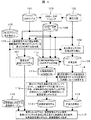
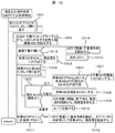
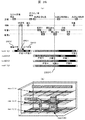
図1は、本発明の一実施形態を適用した建設状況可視化システムの概略構成図である。 FIG. 1 is a schematic configuration diagram of a construction status visualization system to which an embodiment of the present invention is applied.
建設対象のCADモデルは、CADモデル格納部101に記録されている。また、建設の工程データは、建設工程格納部102に記録されている。CAD−工程マッピング処理部103は、上記CADモデルと建設工程データの対応関係を求め、おのおのの関係の対応テーブルをCAD−工程マップテーブル格納部104に格納する。CAD−工程マッピング処理部103の実行と、CAD−工程マップテーブル格納部104へのテーブルの格納は、シミュレーションを実施する前処理として事前に実施しておくことが可能である。
The CAD model to be constructed is recorded in the CAD
可視化システムを利用するユーザは、シミュレーション表示を行いたい日を指定するために、シミュレーション表示指定日格納部105に、表示指示日データを格納する。以降、可視化システムは、表示CADモデル作成処理部106,足場工程抽出処理部108,足場解体時CADモデル作成処理部110,仮想足場生成処理部112,足場表現色決定処理部114,表示処理部117の各処理を順次実行することで、シミュレーション画像を表示する。
A user who uses the visualization system stores display instruction date data in the simulation display designation
以下、全体の処理の概要を示す。データの詳細や、各処理部内のロジック詳細は後述する。 The outline of the overall processing is shown below. Details of data and logic details in each processing unit will be described later.
まず、建設対象のCADモデルの表示を行うために、表示CADモデル作成処理部106は、シミュレーション表示指定日格納部105のデータと、CADモデル格納部101,CAD−工程マップテーブル格納部104,建設工程格納部102を参照することで、表示指定日に据え付けられているCADモデルと据付状態を抽出し、指定日の表示CADモデル格納部107に格納する。
First, in order to display a CAD model to be constructed, a display CAD model
一方、足場の表示モデルを作成するために、まず、足場工程抽出処理部108で建設工程格納部102から、シミュレーション表示指定日格納部105の日を含む足場工程データを抽出し、足場工程格納部109に格納する。その後、足場解体時CADモデル作成処理部110で足場工程格納部109から足場解体開始日を求め、その日の建設対象のCADモデルを、CADモデル格納部101,CAD−工程マップテーブル格納部104,建設工程格納部102を参照し求め、結果を足場解体時CADモデル格納部111に格納する。仮想足場生成処理部112では、格納された足場解体時CADモデルを参照し、足場解体時CADモデルを建設するのに必要となる足場領域を求め、仮想足場モデルとして仮想足場モデル格納部113に格納する。
On the other hand, in order to create a display model of the scaffold, first, the scaffold process
仮想足場モデル格納部113に格納された仮想足場モデルの表現色を求めるために、足場表現色決定処理部114では、シミュレーション表示指定日と、足場工程格納部109の関係から、足場の完成度を求め、完成度に対応した足場の表現色を決定し、足場表現色格納部115に保持する。
In order to obtain the expression color of the virtual scaffold model stored in the virtual scaffold
表示処理部117では、指定日の表示CADモデル格納部107と、各CADモデルの据付状態に対応した据付作業表現色テーブル格納部116を参照し、表示を行う。さらに、仮想足場モデル格納部113に格納された仮想足場モデルを、足場表現色格納部115に格納された足場表現色に従い表示を行う。
The
これらの処理により、ユーザが指示した表示指定日に対応する建設状態のCADモデルと、CADモデルから想定した足場の建設作業状態を3次元上で合成して表示することが可能となる。 Through these processes, the CAD model in the construction state corresponding to the designated display date designated by the user and the construction work state of the scaffold assumed from the CAD model can be combined and displayed in three dimensions.
図2,図3は、CADモデル格納部101内の格納情報を示している。図2は、据付対象物テーブル201である。このテーブルは、据付単位(機器や配管など)毎の情報を保持するテーブルである。格納情報としては、据付対象物毎の、据付対象を識別するUID(Unit ID),対象物の機器種別情報,機器種別毎に対象を識別する機器ID,据え付ける工事エリアを示するエリアNo.,据付位置を示す配置位置,配置回転情報を持つ。
2 and 3 show stored information in the CAD
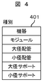
機器種別情報としては、図4に示すような機器種別テーブル401を参照し、対応データを据付対象物テーブル201の対応フィールドに格納する。機器種別としては、具体的には、機器,モジュール,大径配管,小径配管,大径サポート,小径サポート,ダクト,トレイ,躯体などがある。 As the device type information, the device type table 401 as shown in FIG. 4 is referred to, and the corresponding data is stored in the corresponding field of the installation target object table 201. Specific types of equipment include equipment, modules, large-diameter pipes, small-diameter pipes, large-diameter supports, small-diameter supports, ducts, trays, and housings.
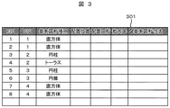
図3は、表示を行うために必要となる図形要素テーブル301である。このテーブルは、据付対象物テーブル201の各据付単位を表示する図形要素を保持している。格納情報としては、要素を識別するEID(Element ID),据付対象を示すUID,基本図形種別情報,基本図形の配置位置,回転,拡大率,基本図形の寸法情報からなる。 FIG. 3 shows a graphic element table 301 necessary for display. This table holds graphic elements for displaying each installation unit of the installation object table 201. The storage information includes an EID (Element ID) for identifying an element, a UID indicating an installation target, basic graphic type information, an arrangement position of a basic graphic, rotation, an enlargement factor, and basic graphic dimension information.
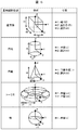
基本図形としては、図6に示す種類のものを用意する。 As a basic figure, the kind shown in FIG. 6 is prepared.
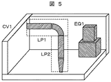
図3の例では、図5に示すようなモデルを表現している。ここでは、EID1,EID2の2つの直方体から構成する機器EQ1(UID1)と、EID3の円柱、EID4のトーラス(の一部)から構成する大径配管LP1(UID2)と、EID5の円柱,EID6の円錐(の一部)から構成する大径配管LP2(UID3)と、EID7,8の直方体などから構成する躯体(UID4)が定義されていることを示している。なお、ここでは、モデルは単純化し、配置情報の詳細は省略している。 In the example of FIG. 3, a model as shown in FIG. 5 is expressed. Here, equipment EQ1 (UID1) composed of two rectangular parallelepipeds EID1 and EID2, a cylinder of EID3, a large diameter pipe LP1 (UID2) composed of (a part of) a torus of EID4, a cylinder of EID5, and EID6 It shows that a large-diameter pipe LP2 (UID3) composed of a cone (part) and a housing (UID4) composed of a rectangular parallelepiped of EID7 and EID8 are defined. Here, the model is simplified, and details of the arrangement information are omitted.
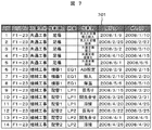
図7は、建設工程格納部102に格納されている建設工程テーブル701を示している。建設工程テーブル701には、各建設作業(アクティビティ)を識別するAID(Activity ID),建設作業を行う工事エリアを示すエリアNo.,作業の区分を示す工事区分情報,作業対象を示す作業項目名,具体的な作業対象を識別する対象情報,個々の作業内容を示す作業名,作業の開始終了日を示す,開始日,終了日情報などを格納している。対象情報フィールドには、CADモデルを識別するID(UID)を格納する。ただし、足場などCADで作成しないモデルに関しては、対象情報フィールドには情報は格納されない。この建設工程テーブル701をガントチャートに表現した例を図8に示す。工程表801の情報は、作業項目(作業対象)を縦軸に、時間を横軸にとり、各作業の発生する時期を、作業の開始日,終了日の情報を元にガントチャート802,803の形式で表現している。
FIG. 7 shows a construction process table 701 stored in the construction
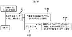
図9は、CADモデル格納部101の情報と、建設工程格納部102の情報から、CADモデルと作業内容を関係づけるCAD−工程マップテーブル格納部104を作成する処理を示している。
FIG. 9 shows a process of creating a CAD-process map
まず、建設工程テーブル701の各作業項目データに関して以下を繰り返す(ステップ901)。建設工程テーブル701の作業項目フィールドに格納されている情報をもとに、対応するCADデータを、据付対象物テーブル201から検索する(ステップ902)。もし、CADデータが存在したならば(ステップ903)、検索されたCADデータのUIDに、処理中の建設工程データのAIDが対応づくものとして、CAD−工程マップテーブル格納部104に登録する(ステップ904)。
First, the following is repeated for each work item data in the construction process table 701 (step 901). Based on the information stored in the work item field of the construction process table 701, the corresponding CAD data is searched from the installation object table 201 (step 902). If CAD data exists (step 903), it is registered in the CAD-process map
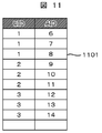
CAD−工程マップテーブル格納部104の内容の具体例を、図11に示す。CAD−工程マップテーブル1101は、CADデータを識別するUIDと、建設工程データを識別するAIDのペアが各レコードになったテーブルである。
A specific example of the contents of the CAD-process map
本実施例の建設状況可視化システムによれば、建設対象のCADモデルと建設工程から、足場などの仮設構造物の概略物量,建設進捗を3次元空間上で把握することが可能となる。 According to the construction status visualization system of the present embodiment, it is possible to grasp the approximate amount of a temporary structure such as a scaffold and the construction progress in a three-dimensional space from the CAD model to be constructed and the construction process.
次に、図1における表示CADモデル作成処理部106の詳細に関して、図10を用いて説明する。この処理は、CADモデル格納部101の情報と、建設工程格納部102の情報と、CAD−工程マップテーブル格納部104の情報を利用し、シミュレーション表示指定日格納部105で示された日の建設据付されている状態をCADモデルから抽出し指定日のCADモデルを作成するものである。
Next, details of the display CAD model
まず、各CADモデルに関して以下の処理を繰り返す(ステップ1001)。なお、処理対象のCADモデルの識別子をUIDとする。 First, the following processing is repeated for each CAD model (step 1001). Note that the identifier of the CAD model to be processed is a UID.
繰り返し処理では、まず、CAD−工程マップテーブル1101を参照し、対象としているUIDに関連する建設工程データのAID(複数)を検索する(ステップ1002)。建設工程データが存在しない場合(ステップ1013)、静的な建造物であるとして、UIDに対応した基本形状を、図形要素テーブル301から抽出し指定日の表示CADモデル格納部107に格納する(ステップ1014)。その後、次のUIDのループ処理に移行するため、以降の処理をスキップする(ステップ1015)。
In the iterative process, first, the CAD-process map table 1101 is referenced to search for AID (s) of construction process data related to the target UID (step 1002). If there is no construction process data (step 1013), the basic shape corresponding to the UID is extracted from the graphic element table 301 and stored in the display CAD
次に、作業用変数として、作業AIDと完成度を設け、作業AIDをNULL、完成度を100%とし(ステップ1003)、ステップ1002で検索された各AIDに対して以下を繰り返す(ステップ1004)。 Next, the work AID and the completeness are provided as work variables, the work AID is NULL, the completeness is 100% (step 1003), and the following is repeated for each AID searched in step 1002 (step 1004). .
AIDに対応する建設工程データと、指定日との関係を求める(ステップ1005)。結果として、既にその作業が完了している場合(つまり、指定日が、作業終了日よりも後の日である)、さらに、作業AIDがNULLまたは、作業AIDよりも現在の対象AIDの方が後作業であれば(ステップ1006)、現在の対象AIDの値を、作業AIDに代入する(ステップ1007)。対象AIDと指定日との関係として、現在作業中(開始日と終了日の間)ならば、現在のAIDを、作業AIDに代入し(ステップ1008)、対象AIDの持つ開始,終了日と、指定日の関係から、完成度を求め代入する。完成度は、開始日から指定日までの日数を、開始日から終了日までの全日数で割った値から求めることが出来る(1009)。その後、AIDに関して処理しているループを終了する(ステップ1010)。 The relationship between the construction process data corresponding to the AID and the designated date is obtained (step 1005). As a result, when the work has already been completed (that is, the specified date is a date after the work end date), the work AID is NULL or the current target AID is more than the work AID. If it is a post-operation (step 1006), the current value of the target AID is substituted into the operation AID (step 1007). As the relationship between the target AID and the specified date, if the current work is in progress (between the start date and the end date), the current AID is substituted into the work AID (step 1008), and the start and end dates of the target AID From the relationship of the specified date, the degree of completion is obtained and substituted. The degree of completion can be obtained from a value obtained by dividing the number of days from the start date to the designated date by the total number of days from the start date to the end date (1009). Thereafter, the processing loop for AID is terminated (step 1010).
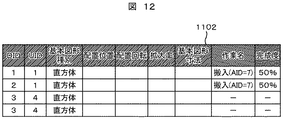
全てのAIDに関して処理を実行したならば、作業AIDの値をチェックし、NULLでない場合、つまり、建設作業が着手済みの場合(ステップ1011)、対象としているUIDに関連した基本形状を、図形要素テーブル301から抽出し、指定日の表示CADモデル格納部107に格納する。表示CADモデル格納部107の内容は、図12に示すような表示図形要素テーブル1102から構成している。表示図形要素テーブル1102には、図形要素毎に、作業名と完成度のフィールドがあり、ステップ1012において、作業名フィールドに作業AIDの値を格納し、完成度フィールドにこれまでの処理で保持している完成度データを格納する。
If the process is executed for all AIDs, the value of the work AID is checked, and if it is not NULL, that is, if the construction work has been started (step 1011), the basic shape related to the target UID is displayed as a graphic element. The data is extracted from the table 301 and stored in the display CAD
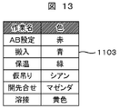
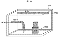
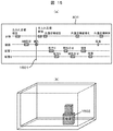
以上の処理の結果、図14の例に示すようなCADモデルと、図15(a)に示すような工程を仮定し、表示指定日として、1501に示す日を指定した場合、図12に示すような結果を得ることが出来る。図14では、躯体1401と、配管1:1403と、配管2:1404、機器1402がCADモデルとして登録されている。据付対象物テーブルは201のようになる。建設工程テーブルは701のような情報となっているものとする。指示日1501は、機器の搬入の中間を指示しているので、表示CADモデル作成処理部106により、表示図形要素テーブル1102は、機器を構成する直方体2つと、躯体を表現する複数の直方体が登録されることになる。また、機器を構成する直方体に関しては、搬入作業を示す作業名と、その時点の完成度50%が記録されている。この状態で、表示処理を行った例を図15(b)に示す。躯体の形状は静的なモデルなので、そのまま表示を行い、機器に関する形状は、完成度50%を示す半透明で、搬入中の状態を示す色により表示される。なお、各作業に対する表現色は、据付状態に対応する据付作業表現色テーブル格納部116内に、図13に示すような、作業表現色テーブル1103で指定されるものとする。この例では、搬入色は青に指定されている。
As a result of the above processing, assuming a CAD model as shown in the example of FIG. 14 and a process as shown in FIG. Such a result can be obtained. In FIG. 14, a
上記処理によれば、足場解体開始の時点で未着手のCADモデルを足場生成の対象から外すことができ、搬入用足場から共通足場の切り替えなど、建設途中での足場の組み換えを考慮した評価を行うことが可能となる。 According to the above process, the CAD model that has not been started can be removed from the scaffold generation target at the start of the scaffold dismantling, and the evaluation considering the recombination of the scaffold during construction, such as switching from the scaffold for carrying in to the common scaffold, etc. Can be done.
次に、足場の表現方法に関して説明する。 Next, a method for expressing the scaffold will be described.
建設作業を行う際には、建設対象の周囲に足場を組み立て、建設作業の作業性を確保する必要がある。一般に、足場の大きさや高さは規格化されている。本実施例のシステムは、このサイズを基準に概略の足場領域を求め、建設工程にあわせた足場の概略と、進捗状態を提示することを目的とする。 When performing construction work, it is necessary to assemble a scaffold around the construction target to ensure the workability of the construction work. In general, the size and height of the scaffold are standardized. The system of a present Example aims at calculating | requiring an outline scaffold area | region on the basis of this size, and showing the outline of a scaffold according to a construction process, and a progress state.
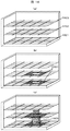
図16に足場を求める処理の概要を示す。まず、建設エリアを高さ方向に足場の基準高さを元に分割し、それぞれを足場のレイヤ1601,1602,1603とする。次に、各レイヤ1601,1602,1603を足場のサイズ(幅,長さ)を基準にメッシュ分割する。機器1605を搬入する場合は、搬入のための足場を機器の周りに搬入前に組み立てる必要がある。図16では、1604が搬入用の足場である。これを求めるために、据付対象となる機器と、各レイヤ上のメッシュの位置を比較し、機器の周囲(作業範囲内)に存在するメッシュを抽出する。これにより、足場位置となるメッシュを選択する。このように、足場領域を求めるためには、表示したい日の機器の据付状態ではなく、建設作業中は、足場の変更が無いものとして、機器の据付が終了した状態を想定して設定する。この足場の領域(仮想足場領域)を求める処理が、図1における足場工程抽出処理部108,足場解体時CADモデル作成処理部110,仮想足場生成処理部112である。
FIG. 16 shows an outline of processing for obtaining a scaffold. First, the construction area is divided in the height direction based on the reference height of the scaffold, and the layers are set as
足場工程抽出処理部108では、建設工程格納部102内の建設工程テーブル701に登録されている建設作業の中から、表示指定日を含む足場工程を抽出する。図7の例で、表示指定日が図15の1501の場合、AID1とAID2が抽出される。その工程データを足場工程格納部109に格納する。
The scaffold process
足場解体時CADモデル作成処理部110では、足場工程格納部に格納された足場の解体開始日を求め、求めた解体開始日の時点の据付状態のCADモデルを作成し、足場解体時CADモデル格納部111に格納する。なお、足場解体開始日のCADモデルを抽出する方法は、図1に示した処理1006と同じアルゴリズムにより実現できる。この時、解体開始日が指定日となる。また、得られる結果は表示図形要素テーブル1102と同様であるが、格納先が足場解体時CADモデル格納部111となる。
The scaffold dismantling CAD model
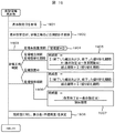
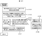
次に、仮想足場生成処理部112により、足場領域を足場解体時CADモデル格納部のデータから求める。詳細のフローを図21に示す。まず、据付対象CADモデル(ここでは、足場解体時CADモデル格納部に保持されたCADモデル)から工事エリアの床形状と高さを取得する(ステップ2101)。ここでは、躯体のモデルを抽出し、その形状から床形状と高さを取得することが出来る。次に、高さ方向を、足場組立の基準高さに分割し、レイヤを作成し、さらに、各レイヤを足場の基準サイズに従いメッシュ分割する(ステップ2102)。次に、各レイヤ上のメッシュ毎に以下の処理を繰り返す(ステップ2103)。
Next, the scaffold region is obtained from the data in the CAD model storage unit at the time of scaffold disassembly by the virtual scaffold
処理中のメッシュの上部、近傍(作業範囲)内にCADモデルが存在し、かつ、そのメッシュの下部にCADモデルが存在しないか判定する(ステップ2104)。判定がYesならば、その処理対象メッシュを足場候補とする(ステップ2105)。さらに、対象メッシュの真下に位置する下部レイヤのメッシュも足場候補とする。これにより、機器の真上に足場を組むことなく、機器の据付作業を行う場所に足場を組むことが可能となる。また、足場を、単独で中空に置くことなく、足場の概略構造を作成することが可能となる。 It is determined whether there is a CAD model in the upper part and vicinity (working range) of the mesh being processed and no CAD model is present in the lower part of the mesh (step 2104). If the determination is Yes, the processing target mesh is set as a scaffold candidate (step 2105). Further, a lower layer mesh located directly below the target mesh is also a scaffold candidate. As a result, it is possible to assemble a scaffold at a place where equipment installation work is performed without assembling a scaffold directly above the equipment. In addition, it is possible to create a schematic structure of the scaffold without placing the scaffold alone in a hollow space.
以上の処理により、足場候補として求めたメッシュに対し、足場基準形状を割り当てて、足場形状モデルを作成する(ステップ2107)。 Through the above processing, a scaffold reference shape is assigned to the mesh obtained as a scaffold candidate to create a scaffold shape model (step 2107).
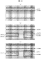
図20の(a)(b)(c)に、図14のCADモデルに対して、完成時を想定した足場候補メッシュの例を各レイヤ(この例では3層)について示す。図14(a)は最上層を示しており、配管1(1403)に対応するモデル2001が選択され、近傍メッシュ2006が足場候補として選択されている。この時、メッシュ2006の下部に位置するメッシュ2007,2008も足場候補として選択される。図14(b)は第2層を示している。ここでは、配管2(1404)に対応するモデル2002とその近傍メッシュ2009が選択され、機器1402に対応するモデル2003とその近傍メッシュ2012が選択されている。メッシュ2010も機器2003の近傍ではあるが、2010の下部メッシュにあたるメッシュ2011に機器モデル2005が存在するため、足場候補としていない。同様に、図14(c)は最下層を示している。
FIGS. 20A, 20B, and 20C show examples of scaffold candidate meshes that are assumed to be completed with respect to the CAD model of FIG. 14 for each layer (three layers in this example). FIG. 14A shows the uppermost layer, in which the
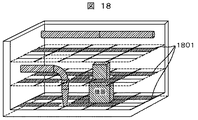
これにより、図18に示すような足場領域の概略形状1801を作成することができる。なお、図18と図20の説明対象モデルは同じであるが、説明図の作画の関係からメッシュの詳細度が異なっている。
Thereby, a
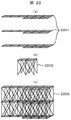
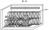
図21のステップ2107での足場形状の作成方法例を、図22に示す。図22(a)では、足場メッシュそのものを足場形状2201とするものである。一方、足場の形状は一般に規格化されており、これを利用して形状を展開することも可能である。例えば、図22(b)のような足場の基本形状2202を用意しておき、(a)に示すような足場領域が与えられた際には、その領域を基本形状で埋めつくすように配置することで概略の足場構造を表現することが可能となる。図22(c)の2203にその例を示す。このようにして、図18の足場概略形状1801に対応して、足場基本形状を利用して表示した例を図23に示す。ここでは、2301が足場形状となっている。
FIG. 22 shows an example of a scaffold shape creation method in
本実施例の建設状況可視化システムによれば、足場サイズを考慮した概略の足場領域形状を把握することが可能となる。 According to the construction status visualization system of the present embodiment, it is possible to grasp a rough scaffold region shape considering the scaffold size.
次に、足場設置作業の進捗度を表現する方法に関して説明する。 Next, a method for expressing the progress of the scaffold installation work will be described.
足場そのものは、詳細に設計し、組立工程を立てるものではない。このため、本実施例のシステムでは、概略の足場設置作業の作業量を把握することを目的とする。従来の建設進捗の可視化システムでは、個々の建設要素(機器や配管など)の据付計画(スケジュール)が作業開始日,終了日により定義されており、このデータに従って、対象の要素が建設進捗に従って、どのような状態(仮置き状態,溶接作業中など)にあるかを個々の要素毎に表現している。一方、足場の場合、足場の設置作業状態が変化するわけではなく、また、個々の足場ごとに計画を行っているわけでもない。さらに、一度設置した足場も、建設進捗に伴い、一度撤去し組みなおしたり、追加して足場を設置したりする作業(盛り替え作業)が必要となり、単純に最終形の形状を表現しても概要をつかみづらいものとなる。そこで、足場設置作業の概略の作業量を把握するために、本実施例では、足場設置に関する概略の作業量,進捗度を、足場が実際に設置されている状態を表現し、さらに、足場全体の表現形式を変化させることで可視化する。これにより、足場に関する作業物量と、進捗量を解りやすく表現することができる。足場の作業物量は、これまでに説明した方法により足場形状を作成することで可能となる。一方、足場作業の進捗度に関しては、以下に述べる方法により求めることが出来る。この処理は、図1における、足場表現色決定処理部114により実現する。詳細の処理を図19に示す。
The scaffold itself is designed in detail and does not establish an assembly process. For this reason, in the system of a present Example, it aims at grasping | ascertaining the work amount of the rough scaffold installation work. In the conventional visualization system for construction progress, the installation plan (schedule) of each construction element (equipment, piping, etc.) is defined by the work start date and end date. The state (temporary placement state, during welding work, etc.) is expressed for each element. On the other hand, in the case of a scaffold, the installation work state of the scaffold does not change, and the planning is not performed for each scaffold. Furthermore, once the scaffolding has been installed, it will be necessary to remove and reassemble the scaffolding once it has been constructed, or to install additional scaffolding (replacement work). Is difficult to grasp. Therefore, in order to grasp the approximate work amount of the scaffold installation work, in this embodiment, the approximate work amount and progress related to the scaffold installation are represented by the state in which the scaffold is actually installed, and further the entire scaffold. Visualize by changing the expression format. Thereby, the amount of work related to the scaffold and the progress amount can be expressed in an easy-to-understand manner. The amount of work on the scaffold can be made by creating the scaffold shape by the methods described so far. On the other hand, the progress of the scaffolding work can be obtained by the method described below. This processing is realized by the scaffold expression color
まず、シミュレーション表示指定日格納部105から表示指定日を取得する(ステップ1901)。次に、取得した表示指定日が、足場工程のどの期間かを足場工程格納部109を参照し求める(ステップ1902)。足場工程の期間により、以下の各処理を実行する(ステップ1903)。もし、足場がまだ設定されていない期間の場合、足場完成度を0%とする(ステップ1904)。もし、足場組立期間もしくは、足場の盛り替え期間の場合、完成度は、指定日までに完成した足場の組み立てに必要であった日数と現在作業中の日数を足した日数を、全組立に必要な日数で割った値とする(ステップ1905)。もし、足場設置中(足場は設置されているが、足場組立作業が無い)の場合、完成度は、それまでに完成した足場の組み立てに必要であった日数を、全組立に必要な日数で割った値とする(ステップ1906)。もし、足場解体期間の場合、完成度は、指定日から解体終了までの日数を、全解体期間の日数で割った値とする(ステップ1907)。
First, a display designation date is acquired from the simulation display designation date storage unit 105 (step 1901). Next, the scaffolding
なお、上記の処理で、複数の足場工程が、先入れ搬入用足場と共通足場のように解体を伴って連続する場合は、別々の作業完成度の扱いとして処理する。一方、共通足場での盛り替えといった一部改修を行うような場合は、一連の盛り替え作業が終了した時点で作業量が100%終了したと考えるものとする。 In the above process, when a plurality of scaffolding steps are continued with dismantling such as a first-in carry-in scaffold and a common scaffold, they are treated as different work completions. On the other hand, in the case of performing a partial repair such as rearranging on a common scaffold, it is assumed that the work amount is 100% completed when a series of rearranging operations are completed.
また、解体時は、足場の完成度を、開始日に100%、解体終了時に0%になるように解体作業日毎に計算することにする。 At the time of dismantling, the completeness of the scaffold is calculated every dismantling work day so that it becomes 100% on the start date and 0% at the end of dismantling.
通常の建設作業(仮置き,溶接など)の可視化では、個々の作業工程に対して、0%で始まり100%で終了するという作業量の計算を行っている。しかしながら、足場の作業は、個々の作業工程(足場設置,盛り替え,解体作業)間で関連して見積もる必要がある。上記の処理により、全体の足場作業の進捗度を直感的に把握することが可能となる。 In visualization of normal construction work (temporary placement, welding, etc.), the amount of work is calculated such that it starts at 0% and ends at 100% for each work process. However, the scaffolding work needs to be estimated in relation to each work process (scaffolding, refilling, dismantling work). Through the above processing, it is possible to intuitively grasp the progress of the entire scaffold work.
次に、以上の処理で求めた完成度に対応して、表示を行う形式を決定し、結果を足場表現色格納部115に格納する(ステップ1908)。具体的には、表示の不透明度を完成度に関連づけて決定することが可能である。これにより、足場作業の進捗に伴い、足場形状が透明から半透明、不透明へと表現されるようになる。また、解体されるに従って、不透明から透明に順次移行するようになる。これにより、直感的に作業の進捗を把握することが可能となる。また、透明度だけでなく、表示色を変化させることで表現することも可能である。さらに、先入れ足場と、共通足場で表示色を異なったものとし、状態を解りやすく表現することも可能である。 Next, the display format is determined according to the degree of completion obtained by the above processing, and the result is stored in the scaffold expression color storage unit 115 (step 1908). Specifically, the display opacity can be determined in association with the degree of completion. As a result, as the scaffold work progresses, the scaffold shape is expressed from transparent to translucent and opaque. In addition, as it is dismantled, it gradually shifts from opaque to transparent. This makes it possible to intuitively grasp the work progress. It is also possible to express not only the transparency but also the display color. Furthermore, the display colors can be made different between the first-in scaffold and the common scaffold, and the state can be expressed easily.
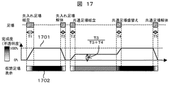
具体的な完成度の表現例を図17に示す。 An example of a specific expression of completeness is shown in FIG.
この例では、足場は先入れ足場組立をT1日、先入れ足場解体をT2日で実施する。次に、建設作業用に、共通足場組立をT3日、共通足場盛り替えをT4日、共通足場解体をT5日で実施する計画としている。この時の足場作業の完成度推移は1701のようになる。足場が存在しない時点では0%、先行足場は盛り替え作業が無いので、先行足場組立作業で0%から100%に遷移する。完成してから解体までの期間は100%。先入れ足場解体で、T2日の間に100%から0%に遷移する。さらに、共通足場に関しては、組立期間で、0%からT3/(T3+T4)%の値になる。これは、盛り替え作業の部分が残っているためである。その後、盛り替え期間のT4日で、T3/(T3+T4)%から100%に遷移し、その後、解体まで100%となる。さらに、解体のT5日をかけて、100%から0%に遷移する。 In this example, the scaffold performs first-in-place scaffold assembly on T1 day and the first-in scaffold dismantling on T2 days. Next, for construction work, the common scaffold assembly is scheduled to be implemented on T3 days, the common scaffold replacement will be implemented on T4 days, and the common scaffold dismantling will be implemented on T5 days. The completeness transition of the scaffolding work at this time is as 1701. When there is no scaffold, 0%, and since there is no reordering work for the preceding scaffold, transition from 0% to 100% in the preceding scaffold assembling work. The period from completion to dismantling is 100%. It will be 100% to 0% during T2 days in the first-in-place scaffold dismantling. Furthermore, the common scaffold is a value from 0% to T3 / (T3 + T4)% during the assembly period. This is because the part of the rearrangement work remains. After that, on T4 day of the replacement period, the transition is made from T3 / (T3 + T4)% to 100%, and then 100% until dismantling. Furthermore, it changes from 100% to 0% over T5 days of dismantling.
このような完成度の遷移に対応し、足場形状の表示を1702のように遷移させる。ここで、白は透明、灰色は半透明、黒は不透明を表現している。 Corresponding to such a transition of completeness, the display of the scaffold shape is changed as indicated by 1702. Here, white represents transparency, gray represents translucency, and black represents opacity.
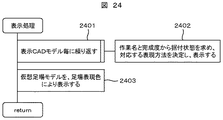
最後に、図1の表示処理部117により、据付対象のCADモデルと足場の形状の表示を行う。処理の詳細を図24に示す。まず、指定日の表示CADモデル格納部107内の表示図形要素テーブル1102を参照し、表示CADモデル毎に以下を繰り返す(ステップ2401)。まず、表示図形要素テーブル1102から、そのモデルがその時点で実施中の作業を作業名フィールドから求め、その作業名に対応する表現方法を、据付状態に対応する据付作業表現色テーブル格納部116内の、作業表現色テーブル1103から求める。求めた表現色で、モデルの表示を行う。なお、この時、作業名と作業の完成度の情報から、前後の作業の色を利用し中間の色を作成し表現しても良い(ステップ2402)。
Finally, the
その後、仮想足場モデル格納部113に保持した足場形状と、足場表現色格納部115に保持した表現色を利用し、足場形状の表示を行う(ステップ2403)。
Thereafter, the scaffold shape is displayed using the scaffold shape held in the virtual scaffold
以上の処理により、建設対象のCADモデルに対して、足場の概略形状を表現し、建設工程に従って、足場作業の完成度をわかりやすく表現することが可能となる。また、足場組立作業,解体作業量に対応した表示が可能となり、全体の進捗を把握することが可能となる。 With the above processing, it is possible to express the schematic shape of the scaffold for the CAD model to be constructed, and to express the completeness of the scaffold work in an easy-to-understand manner according to the construction process. In addition, the display corresponding to the scaffold assembly work and the disassembly work amount can be performed, and the overall progress can be grasped.
次に、足場の表現に建設作業の状態を表現する実施例を説明する。 Next, an embodiment in which the state of construction work is expressed in the expression of the scaffold will be described.
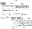
本実施例は、図1でこれまで示した実施例と同じ構成となる。本実施例では表示処理部117における表示処理が異なる。詳細の処理を図25に示す。
This embodiment has the same configuration as the embodiment shown so far in FIG. In the present embodiment, the display processing in the
ステップ2501,ステップ2502,ステップ2503は、図24のステップ2401,ステップ2402,ステップ2403のそれぞれと同じである。次に、足場メッシュ毎に、以下の処理を繰り返す(ステップ2504)。
処理対象となるメッシュから見て、作業範囲内(手が届く範囲内)の近傍に建設対象のCADモデルがあるか検索を行う(ステップ2505)。検索された近傍のCADモデルに対して、表示指定日の作業状態を求める(ステップ2506)。もし、作業中のモデルの数が無ければ足場メッシュの表示はそのまま。1つの場合は、CADモデルの作業内容に対応した表示色で、メッシュもしくは足場形状モデルを表示する(ステップ2509)。もし、作業中のモデルが複数存在する場合は、作業が干渉していることになるため、あらかじめ決めた警告色または、警告のシンボルをメッシュ上に表示する(ステップ2508)。 A search is made as to whether there is a CAD model to be constructed in the vicinity of the work range (within the reach of the hand) as seen from the mesh to be processed (step 2505). The working state of the specified display date is obtained for the searched nearby CAD model (step 2506). If there are no working models, the scaffold mesh display will remain as it is. In one case, the mesh or scaffold shape model is displayed in a display color corresponding to the work content of the CAD model (step 2509). If there are a plurality of models being worked, the work is interfering with each other, so a predetermined warning color or warning symbol is displayed on the mesh (step 2508).
具体的な表示例を図26,図27に示す。 Specific display examples are shown in FIGS.
図26(a)に示す建設工程で、建設状態の表示を行うことを考える。図26(b)が表示例を示す。図26(b)に示した3箇所のメッシュ位置の表現色の遷移を、図26(a)の下部に示す。それぞれのメッシュは、近傍のCADモデルが作業中の場合、そのCADモデルの表現色でメッシュを表現している。表示指定日が2604の場合、図26(b)に示すような表示となる。配管2が開先合せ作業中なので、その近傍に当たるメッシュ(mesh2,1,2)の表現色が異なっている。ここでは、図13の作業表現色テーブル1103を参照し、マゼンダで表現されることになる。また、単純に、作業の種類に係わらず1つの作業色で表現しても良い。
Consider that the construction status is displayed in the construction process shown in FIG. FIG. 26B shows a display example. The transition of the expression color at the three mesh positions shown in FIG. 26B is shown in the lower part of FIG. Each mesh represents the mesh with the expression color of the CAD model when a nearby CAD model is in operation. When the designated display date is 2604, the display is as shown in FIG. Since the
また、作業中の表示期間は、実際の工程上の作業日程に合わせてもよいが、各作業の前後に、準備作業期間,完了作業期間を設け、その期間を含めて表現色を変更することも出来る。例えば、図26(a)の機器のAB設定作業の表示期間2601を、AB設定の開始前の準備作業期間2602,終了後の完了作業期間2603を含めて表現することが出来る。これにより、工程上では表現できない作業エリアの占有状態を表現することが出来る。なお、準備作業や完了作業の日数は、作業毎に事前に定義しておく。この時、作業物量に応じて、日数を変化させることも可能である。
In addition, the display period during the work may be in accordance with the work schedule in the actual process, but before and after each work, a preparation work period and a completion work period are provided, and the expression color is changed including that period. You can also. For example, the
図27では、作業が干渉している場合の表現方法例を示している。 FIG. 27 shows an example of an expression method when work is interfering.
図27(a)の建設工程で、表示指定日2604を表現することを例にしている。ここで、機器の保温作業2701の作業期間2702と、配管2の開先合わせの作業期間2703が足場メッシュ(mesh2,3,3)で干渉している。干渉していることを示すシンボル2705をメッシュ上に表現し、警告を発している様子を示している。
In the construction process of FIG. 27A, the display designated
以上の処理により、足場モデルを利用した作業進捗の状況表現と、作業間の干渉チェックを行うことが可能となる。特に、CADモデルの表現色を変えるだけでは、細かい対象物への作業が見落とされる可能性があるが、本実施例では、足場を介して作業状況を把握することができるので、見落としすることなく、作業状況を把握することが可能となる。 Through the above processing, it is possible to perform a work progress situation expression using a scaffold model and an interference check between works. In particular, there is a possibility that work on a fine object may be overlooked simply by changing the expression color of the CAD model. However, in this embodiment, the work situation can be grasped via a scaffold, so that it is not overlooked. It becomes possible to grasp the work situation.
さらに前記実施例では、干渉しているメッシュやシンボルをキーボードやポインタなどの入力装置を用いて指定すると、前記干渉に関連するCADモデルが明示されるようにしてもよい。これにより、複数のCADモデルが存在する場合でも、どの作業が干渉しているか、CADモデルを用いて把握することが可能となる。例えば、図27で足場メッシュ(mesh2,3,3)又は干渉していることを示すシンボル2705を指定することにより、機器の保温作業2701と関連付けられたCADモデルと、配管2の作業期間2703と関連付けられたCADモデルを強調表示等行う。設定によっては干渉に関連するいずれかのCADモデルを強調表示等してもよい。
Further, in the embodiment, when the interfering mesh or symbol is designated using an input device such as a keyboard or a pointer, a CAD model related to the interference may be specified. As a result, even when there are a plurality of CAD models, it is possible to determine which work is interfering using the CAD model. For example, by specifying a scaffold mesh (mesh2,3,3) or a
以上の実施例は、中央演算装置(CPU)とメモリ,補助記憶装置,キーボードなどの入力装置,画面などの表示装置からなるコンピュータシステム上で構成される。各処理ステップはメモリ上にプログラムとして記述され、中央処理装置により実行される。また、表示指定日の指示や、表示対象の選択や条件入力などは、ユーザからキーボードなどの入力装置を介して入力され、結果は、メモリや補助記憶装置に格納される。また、3次元画像表示など画面を通してユーザに提示される。 The above embodiments are configured on a computer system including a central processing unit (CPU), a memory, an auxiliary storage device, an input device such as a keyboard, and a display device such as a screen. Each processing step is described as a program in the memory and executed by the central processing unit. In addition, an instruction to specify a display date, selection of a display target, condition input, and the like are input from a user via an input device such as a keyboard, and the result is stored in a memory or an auxiliary storage device. Also, it is presented to the user through a screen such as a three-dimensional image display.
また、実施に当たり、各処理系はネットワークを介した環境により実現することも可能である。 In implementation, each processing system can be realized by an environment via a network.
本実施例の建設状態可視化システムによれば、細かいCADモデルで表示が隠れる場合でも、近傍の足場の表示により作業状況を把握することが可能となる。また、異なった建設作業が同じ場所で計画されている場合に干渉することを警告することが可能となる。 According to the construction state visualization system of the present embodiment, even when the display is hidden by a fine CAD model, it is possible to grasp the work status by displaying a nearby scaffold. It is also possible to warn of interference when different construction operations are planned at the same location.
101 CADモデル格納部
102 建設工程格納部
103 CAD−工程マッピング処理部
104 CAD−工程マップテーブル格納部
105 シミュレーション表示指定日格納部
106 表示CADモデル作成処理部
107 表示CADモデル格納部
108 足場工程抽出処理部
109 足場工程格納部
110 足場解体時CADモデル作成処理部
111 足場解体時CADモデル格納部
112 仮想足場生成処理部
113 仮想足場モデル格納部
114 足場表現色決定処理部
115 足場表現色格納部
116 据付作業表現色テーブル格納部
117 表示処理部
201 据付対象物テーブル
301 図形要素テーブル
701 建設工程テーブル
1101 CAD−工程マップテーブル
1102 表示図形要素テーブル
1103 作業表現色テーブル
101 CAD
Claims (11)
建設対象の3次元CADモデルを保持するCADモデル格納部と、
建設の工程データを保持する建設工程格納部と、
建設作業に必要となる足場の領域と形状を、上記CADモデルと建設工程データから作成する足場モデル作成処理部と、
前記建設工程格納部の建設工程データから、足場に関する工程データを抽出する足場工程抽出処理部と、
可視化対象日における足場の完成度を、対象日と上記足場工程データの関係から決定し、足場の表現形式を求める足場表現形式決定処理部と、
前記足場領域を、求めた足場の表現形式に従い、上記CADモデルと同時に表示する表示処理部とを保持することを特徴とする建設状況可視化システム。 In a computer system that visualizes construction plans and progress,
A CAD model storage unit for holding a three-dimensional CAD model to be constructed;
A construction process storage for holding construction process data;
A scaffold model creation processing unit for creating a scaffold area and shape necessary for construction work from the CAD model and construction process data;
From the construction process data of the construction process storage unit, a scaffold process extraction processing unit that extracts process data related to the scaffold,
A scaffold expression format determination processing unit that determines the completeness of the scaffold on the visualization target date from the relationship between the target date and the scaffold process data, and obtains the expression format of the scaffold,
A construction status visualization system, comprising: a display processing unit that displays the scaffold area simultaneously with the CAD model according to the obtained representation format of the scaffold.
該足場モデル作成処理部は、
建設対象の空間を、足場基準高さを基準に、高さ方向に分割することでレイヤを作成し、さらに、各レイヤを、足場の幅サイズを基準にメッシュ分割する処理部と、
上記メッシュ毎に、メッシュ上部近傍にCADモデルが存在し、かつ、メッシュ下部にCADモデルが存在しない場合、該メッシュと、該下部メッシュを足場領域とする処理部と、
足場領域と決定したメッシュに対して、足場モデルを生成する処理部と、
を保持することを特徴とする建設状況可視化システム。 The construction status visualization system according to claim 1,
The scaffold model creation processing unit
A processing unit that creates a layer by dividing the space to be constructed in the height direction based on the scaffold reference height, and further, meshes each layer based on the width size of the scaffold,
For each mesh, when a CAD model is present near the upper part of the mesh and no CAD model is present at the lower part of the mesh, the mesh and a processing unit that uses the lower mesh as a scaffold region;
A processing unit that generates a scaffold model for the mesh determined as the scaffold region;
Construction status visualization system characterized by holding
足場モデルを作成するために参照するCADモデルを、可視化対象日が含まれる足場工程に示されている足場解体開始日の時点で建設されている状態のCADモデルとする処理部を保持することを特徴とする建設状態可視化システム。 In the construction status visualization system according to claim 2,
It is assumed that a processing unit that holds a CAD model to be referred to for creating a scaffold model as a CAD model in a state of being constructed at the scaffold disassembly start date shown in the scaffold process including the visualization target date is held. A construction status visualization system.
該足場表現形式決定処理部における足場完成度の演算は、
足場解体までの状態では、足場組立作業日数,足場盛り替え作業日数の総計から、総組立作業日数を求め、これを100%とし、可視化対象日までに終了している作業日数の割合を完成度として計算し、
足場解体開始から終了までは、解体作業日数を総作業日数として求め、これを100%とし、可視化対象日での残解体作業日数の割合を完成度として計算することを特徴とする建設状況可視化システム。 In the construction status visualization system according to any one of claims 1 to 3,
The calculation of the scaffold completeness in the scaffold expression format determination processing unit is as follows:
In the state up to the dismantling of the scaffold, the total assembly work days are calculated from the total number of scaffold assembly work days and scaffold remounting work days, and this is taken as 100%, and the percentage of work days that have been completed by the visualization target day Calculate as
From the start to the end of scaffold dismantling, the construction status visualization system is characterized in that the total number of work days is calculated as 100%, and the percentage of the remaining dismantling work days on the visualization target day is calculated as the degree of completion. .
該表示処理部は、さらに、
足場領域メッシュ毎に、上方近傍に存在するCADモデルを検索する処理部と、
検索したCADモデルに関する、表示対象日における作業状況を求める処理部と、
該CADモデルに関する作業が、作業中の場合、該メッシュを作業中であることを明示するよう表示を行う処理部と、
検索した結果、作業中のCADモデルが複数である場合、作業が干渉していることをメッシュ上に明示する表示を行う処理部を保持することを特徴とする、建設状態可視化システム。 In the construction status visualization system according to any one of claims 1 to 4,
The display processing unit further includes:
For each scaffold area mesh, a processing unit that searches for a CAD model existing in the upper vicinity;
A processing unit for obtaining a work status on a display target day concerning the searched CAD model;
A processing unit that displays to clearly indicate that the mesh is being worked when the work related to the CAD model is being worked;
As a result of the search, when there are a plurality of CAD models being worked, a construction state visualization system is provided, which holds a processing unit that displays on the mesh that the work is interfering.
建設作業に必要となる足場の領域と形状を、建設対象の3次元CADモデルと建設工程データから作成し、
前記建設工程データから、足場に関する工程データを抽出し、
可視化対象日における足場の完成度を、対象日と上記足場に関する工程データの関係から決定し、足場の表現形式を求め、
前記足場の領域を、求めた足場の表現形式に従い、上記CADモデルと同時に表示することを特徴とする建設状況可視化システムの処理方法。 A computer system that visualizes construction plans and progress,
Create the area and shape of the scaffolding necessary for construction work from the 3D CAD model and construction process data to be constructed,
From the construction process data, extract process data related to the scaffold,
Determine the completeness of the scaffold on the visualization target day from the relationship between the target date and the process data related to the above scaffold, and obtain the expression form of the scaffold,
A method of processing a construction status visualization system, wherein the scaffold area is displayed simultaneously with the CAD model in accordance with the obtained representation format of the scaffold.
該足場の領域と形状の作成は、
建設対象の空間を、足場基準高さを基準に、高さ方向に分割することでレイヤを作成し、さらに、各レイヤを、足場の幅サイズを基準にメッシュ分割し、
上記メッシュ毎に、メッシュ上部近傍にCADモデルが存在し、かつ、メッシュ下部にCADモデルが存在しない場合、該メッシュと、該下部メッシュを足場領域とし、
足場領域と決定したメッシュに対して、形状を生成することを特徴とする建設状況可視化システムの処理方法。 In the processing method of the construction status visualization system according to claim 1,
Creating the scaffold area and shape
Create a layer by dividing the space to be constructed in the height direction based on the scaffold reference height, and further, each layer is mesh-divided based on the scaffold width size,
For each mesh, when a CAD model is present near the upper part of the mesh and no CAD model is present at the lower part of the mesh, the mesh and the lower mesh are used as a scaffold region,
A processing method of a construction status visualization system, wherein a shape is generated for a mesh determined as a scaffold region.
足場モデルを作成するために参照するCADモデルを、可視化対象日が含まれる足場工程に示されている足場解体開始日の時点で建設されている状態のCADモデルとすることを特徴とする建設状態可視化システムの処理方法。 In the processing method of the construction status visualization system according to claim 7,
The CAD model that is referred to in order to create the scaffold model is a CAD model that is being constructed at the time of the scaffold dismantling start date shown in the scaffold process including the visualization target date. Visualization system processing method.
足場完成度の演算は、
足場解体までの状態では、足場組立作業日数,足場盛替え作業日数の総計から、総組立作業日数を求め、これを100%とし、可視化対象日までに終了している作業日数の割合を完成度として計算し、
足場解体開始から終了までは、解体作業日数を総作業日数として求め、これを100%とし、可視化対象日での残解体作業日数の割合を完成度として計算することを特徴とする建設状況可視化システムの処理方法。 In the processing method of the construction condition visualization system in any one of Claim 6 to 8,
The calculation of scaffolding completeness is
In the state up to the dismantling of the scaffold, the total assembly work days are calculated from the total number of scaffold assembly work days and scaffold replacement work days, and this is taken as 100%, and the percentage of work days that have been completed by the visualization target day Calculate as
From the start to the end of scaffold dismantling, the construction status visualization system is characterized in that the total number of work days is calculated as 100%, and the percentage of the remaining dismantling work days on the visualization target day is calculated as the degree of completion. Processing method.
該表示は、さらに、
足場領域メッシュ毎に、上方近傍に存在するCADモデルを検索し、
検索したCADモデルに関する、表示対象日における作業状況を求め、
該CADモデルに関する作業が、作業中の場合、該メッシュを作業中であることを明示し、
検索した結果、作業中のCADモデルが複数である場合、作業が干渉していることをメッシュ上に明示することを特徴とする建設状態可視化システム。 In the processing method of the construction condition visualization system in any one of Claim 6 to 9,
The display further includes
For each scaffold area mesh, search for the CAD model existing in the upper vicinity,
Find the work status on the display target date for the searched CAD model,
If work on the CAD model is working, indicate that the mesh is working;
As a result of the search, when there are a plurality of CAD models in operation, the construction state visualization system is characterized by clearly showing on the mesh that the operation is interfering.
建設対象の空間を、足場基準高さを基準に、高さ方向に分割したレイヤと、前記レイヤを足場の幅サイズを基準に分割したメッシュを有するデータベースと、
前記メッシュ毎に、対応して存在するCADモデルを有するデータベースとを有し、
作業が干渉しているメッシュ上を強調表示し、
さらに前記メッシュを指定すると、前記メッシュに関するCADモデルを強調表示することを特徴とする建設状態可視化システムの処理方法。 A computer system that visualizes construction plans and progress,
A database having a layer obtained by dividing the space to be constructed in the height direction based on the scaffold reference height, and a mesh obtained by dividing the layer based on the width size of the scaffold;
A database having a corresponding CAD model for each mesh;
Highlight the mesh where the work is interfering,
Furthermore, when the mesh is specified, a CAD model related to the mesh is highlighted, and the processing method of the construction state visualization system is characterized.
Priority Applications (2)
| Application Number | Priority Date | Filing Date | Title |
|---|---|---|---|
| JP2008280670A JP2010108321A (en) | 2008-10-31 | 2008-10-31 | Construction progress visualization system |
| US12/607,543 US8249909B2 (en) | 2008-10-31 | 2009-10-28 | System and method for visualizing the construction progress of scaffolding utilizing 3D CAD models |
Applications Claiming Priority (1)
| Application Number | Priority Date | Filing Date | Title |
|---|---|---|---|
| JP2008280670A JP2010108321A (en) | 2008-10-31 | 2008-10-31 | Construction progress visualization system |
Publications (1)
| Publication Number | Publication Date |
|---|---|
| JP2010108321A true JP2010108321A (en) | 2010-05-13 |
Family
ID=42132555
Family Applications (1)
| Application Number | Title | Priority Date | Filing Date |
|---|---|---|---|
| JP2008280670A Pending JP2010108321A (en) | 2008-10-31 | 2008-10-31 | Construction progress visualization system |
Country Status (2)
| Country | Link |
|---|---|
| US (1) | US8249909B2 (en) |
| JP (1) | JP2010108321A (en) |
Cited By (9)
| Publication number | Priority date | Publication date | Assignee | Title |
|---|---|---|---|---|
| JP2012242981A (en) * | 2011-05-18 | 2012-12-10 | Hitachi-Ge Nuclear Energy Ltd | Plant construction process generation support system, plant construction process generation support method, and program |
| KR20180099445A (en) | 2017-02-27 | 2018-09-05 | 가부시끼가이샤 도시바 | Working area visualization apparatus and working area visualization method |
| JP2019513252A (en) * | 2016-03-15 | 2019-05-23 | ペリ ゲゼルシャフト ミット ベシュレンクテル ハフツングPeri Gmbh | How to build an industrial plant |
| JP2019516028A (en) * | 2016-03-15 | 2019-06-13 | ペリ ゲゼルシャフト ミット ベシュレンクテル ハフツングPeri Gmbh | A method of providing and assembling scaffolding units, each of which will be assembled from individual scaffolding components for construction of a plant, in particular an oil refinery |
| US10360315B2 (en) | 2011-10-03 | 2019-07-23 | Hitachi, Ltd. | Construction field management method and construction field management device |
| JP2021021983A (en) * | 2019-07-24 | 2021-02-18 | 株式会社奥村組 | Building construction management device |
| JP2022186548A (en) * | 2021-06-05 | 2022-12-15 | 株式会社高橋仮設 | Scaffolding material allocation calculation system and scaffolding material allocation calculation method |
| JP2022186549A (en) * | 2021-06-05 | 2022-12-15 | 株式会社高橋仮設 | Scaffolding materials simple calculation system and scaffolding materials simple calculation method |
| JP2024073254A (en) * | 2022-11-17 | 2024-05-29 | 三菱電機株式会社 | Repair planning support system, repair planning support device, repair planning support method, and repair planning support program |
Families Citing this family (29)
| Publication number | Priority date | Publication date | Assignee | Title |
|---|---|---|---|---|
| CN101889119B (en) * | 2007-10-24 | 2013-06-19 | 泰科热控有限责任公司 | Manufacture of heat trace cable, design, installation, and management, and method thereof |
| US9953459B2 (en) * | 2008-11-05 | 2018-04-24 | Hover Inc. | Computer vision database platform for a three-dimensional mapping system |
| US8421800B2 (en) * | 2009-05-29 | 2013-04-16 | Siemens Product Lifecycle Management Software Inc. | System and method for selectable display in object models |
| JP4982531B2 (en) * | 2009-07-28 | 2012-07-25 | 日立Geニュークリア・エナジー株式会社 | Work area arrangement support apparatus, method, program, and recording medium |
| US8531459B1 (en) * | 2010-01-14 | 2013-09-10 | Pma Technologies, Llc | Graphical forensic scheduling system |
| JP5557622B2 (en) * | 2010-06-30 | 2014-07-23 | 日立Geニュークリア・エナジー株式会社 | Construction simulation method and apparatus |
| US9852238B2 (en) * | 2014-04-24 | 2017-12-26 | The Board Of Trustees Of The University Of Illinois | 4D vizualization of building design and construction modeling with photographs |
| JP6578366B2 (en) * | 2015-10-05 | 2019-09-18 | 株式会社小松製作所 | Construction management system |
| US10924881B2 (en) * | 2016-03-03 | 2021-02-16 | Husqvarna Ab | Device for determining construction device and worker position |
| US10387657B2 (en) * | 2016-11-22 | 2019-08-20 | Aon Global Operations Ltd (Singapore Branch) | Systems and methods for cybersecurity risk assessment |
| US10635841B2 (en) | 2017-02-23 | 2020-04-28 | OPTO Interactive, LLC | Method of managing proxy objects |
| DE102018108748A1 (en) * | 2017-04-14 | 2018-10-18 | Gulfstream Aerospace Corporation | SYSTEM AND METHOD FOR PROVIDING A VIRTUAL AIRCRAFT CONSTRUCTION PROCESS |
| US11250176B2 (en) | 2017-05-05 | 2022-02-15 | Nucor Corporation | System for on-site tracking, managing, planning and staging construction projects |
| NO345434B1 (en) * | 2017-08-18 | 2021-02-01 | Beerenberg Corp As | Method and modelling tool for scaffolding design |
| CN107729686B (en) * | 2017-11-08 | 2021-07-27 | 国泰新点软件股份有限公司 | Building model component display method and device, electronic equipment and storage medium |
| JP7245839B2 (en) | 2017-12-29 | 2023-03-24 | 株式会社ミツトヨ | Inspection program editing environment with automatic transmission behavior for occluded workpiece features |
| US11288412B2 (en) | 2018-04-18 | 2022-03-29 | The Board Of Trustees Of The University Of Illinois | Computation of point clouds and joint display of point clouds and building information models with project schedules for monitoring construction progress, productivity, and risk for delays |
| US11532141B1 (en) | 2018-05-25 | 2022-12-20 | Strukshur Inc. | AR/VR interface for client/contractor communication platform |
| CN109610828A (en) * | 2018-12-11 | 2019-04-12 | 中天建设集团有限公司 | Skyscraper Deepen Design afflux inserts complete construction method |
| CN110399513B (en) * | 2019-03-15 | 2020-04-14 | 广州市新誉工程咨询有限公司 | Real-time query device for building data |
| KR102433186B1 (en) * | 2019-04-12 | 2022-08-18 | 레고 에이/에스 | Device, method and computer program product for checking a stabiltiy |
| KR102341778B1 (en) | 2019-04-12 | 2021-12-22 | 레고 에이/에스 | Method for determining assembly sequence and generating instruction of assembling toy |
| CN110378588B (en) * | 2019-07-10 | 2023-02-03 | 重庆大学 | A Contract Spatialization System |
| CN112132531B (en) * | 2020-08-17 | 2023-08-25 | 国网河北省电力有限公司大名县供电分公司 | Overhead line construction progress metering device and overhead line construction progress visualization method |
| US11650724B1 (en) | 2021-01-27 | 2023-05-16 | Pma Technologies, Llc | Schedule density zooming |
| CN113012288B (en) * | 2021-04-02 | 2022-04-22 | 长江空间信息技术工程有限公司(武汉) | Three-dimensional dynamic visualization method for long-distance engineering construction progress |
| CN113553650B (en) * | 2021-07-28 | 2024-05-07 | 中国十七冶集团有限公司 | A BIM-based building construction management system |
| CN115563675A (en) * | 2022-09-29 | 2023-01-03 | 五冶集团上海有限公司 | A construction method of pile foundation engineering based on BIM technology |
| CN116881531A (en) * | 2023-06-21 | 2023-10-13 | 浙江数智交院科技股份有限公司 | BIM-based tunnel electromechanical pipeline buried leakage detection method |
Citations (7)
| Publication number | Priority date | Publication date | Assignee | Title |
|---|---|---|---|---|
| JPH09114872A (en) * | 1995-10-13 | 1997-05-02 | Taisei Corp | Temporary scaffold elevation drawing creation device |
| JPH09268760A (en) * | 1996-03-28 | 1997-10-14 | Shimizu Corp | Process planning management support system |
| JP2001249985A (en) * | 1999-12-27 | 2001-09-14 | Ohbayashi Corp | Execution plan supporting system, execution plan supporting method, and recording medium recorded with computer program for realizing execution plan supporting system |
| JP2002266498A (en) * | 2001-03-08 | 2002-09-18 | Toshiba Corp | Power plant construction planning equipment |
| JP3524389B2 (en) * | 1998-07-31 | 2004-05-10 | 株式会社日立製作所 | Temporary scaffold design support method, system for realizing the method, and recording medium recording program |
| JP2004151984A (en) * | 2002-10-30 | 2004-05-27 | Jgc Corp | Construction work management device |
| JP2006024073A (en) * | 2004-07-09 | 2006-01-26 | Hitachi Plant Eng & Constr Co Ltd | Construction plan expression method, construction plan expression system, and object display method with shape change |
Family Cites Families (35)
| Publication number | Priority date | Publication date | Assignee | Title |
|---|---|---|---|---|
| US4700318A (en) * | 1983-12-09 | 1987-10-13 | Stuart Ockman | Project construction with depiction means and methods |
| US4875162A (en) * | 1987-10-28 | 1989-10-17 | International Business Machines Corporation | Automated interfacing of design/engineering software with project management software |
| US5189606A (en) * | 1989-08-30 | 1993-02-23 | The United States Of America As Represented By The Secretary Of The Air Force | Totally integrated construction cost estimating, analysis, and reporting system |
| JPH03291763A (en) | 1990-04-10 | 1991-12-20 | Shimizu Corp | Execution scheme supporting system for steel-frame construction |
| US5381332A (en) * | 1991-12-09 | 1995-01-10 | Motorola, Inc. | Project management system with automated schedule and cost integration |
| US5974391A (en) * | 1994-07-12 | 1999-10-26 | Fujitsu Limited | Device and method for project management |
| JP3564749B2 (en) | 1994-08-26 | 2004-09-15 | 株式会社日立製作所 | Process plan evaluation device |
| US5689705A (en) * | 1995-02-13 | 1997-11-18 | Pulte Home Corporation | System for facilitating home construction and sales |
| JPH108706A (en) | 1996-06-21 | 1998-01-13 | Hitachi Ltd | Planning method for rehabilitation of temporary scaffolds |
| US6037945A (en) * | 1997-12-16 | 2000-03-14 | Xactware, Inc. | Graphical method for modeling and estimating construction costs |
| US6038547A (en) * | 1998-01-07 | 2000-03-14 | Casto; Robin L. | Construction tracking and payment method and system |
| IT1312245B1 (en) * | 1998-04-10 | 2002-04-09 | Ricoh Kk | APPARATUS, PROCESS FOR IMAGE PROCESSING AND SUPPORT FOR READABLE REGISTRATION BY PROCESSOR WITH PROGRAM REGISTERED ON |
| JP3892593B2 (en) | 1998-10-02 | 2007-03-14 | 株式会社竹中工務店 | Construction status diagram output device and recording medium |
| US6446053B1 (en) * | 1999-08-06 | 2002-09-03 | Michael Elliott | Computer-implemented method and system for producing a proposal for a construction project |
| JP2001142926A (en) | 1999-11-16 | 2001-05-25 | Hitachi Ltd | Yard planning support system in plant construction |
| US6859768B1 (en) * | 2000-03-03 | 2005-02-22 | The Beck Technology | Computer-implemented automated building design and modeling and project cost estimation and scheduling system |
| US7031930B2 (en) * | 2000-12-29 | 2006-04-18 | General Electric Capital Corporation | Project management for complex construction projects by monitoring subcontractors in real time |
| US7283975B2 (en) * | 2001-02-05 | 2007-10-16 | Broughton W Curtis | System and method for tracking and managing construction projects |
| US7720703B1 (en) * | 2001-02-05 | 2010-05-18 | Trimble Navigation Limited | System and method for tracking and managing construction projects |
| US7042468B2 (en) * | 2001-05-04 | 2006-05-09 | Disney Enterprises, Inc. | Text overlay for multi-dimensional construction project models |
| US20040205519A1 (en) * | 2002-01-10 | 2004-10-14 | Chris Chapel | Method and system for automatically generating construction documents |
| JP4033291B2 (en) * | 2002-05-29 | 2008-01-16 | 株式会社日立製作所 | Project risk management system |
| US7409392B2 (en) * | 2002-08-16 | 2008-08-05 | Gcc, Inc. | System and method for managing construction projects |
| US20040236711A1 (en) * | 2003-05-21 | 2004-11-25 | Bentley Systems, Inc. | System and method for automating the extraction of information contained within an engineering document |
| US7103434B2 (en) * | 2003-10-14 | 2006-09-05 | Chernyak Alex H | PLM-supportive CAD-CAM tool for interoperative electrical and mechanical design for hardware electrical systems |
| US20060044307A1 (en) * | 2004-08-24 | 2006-03-02 | Kyuman Song | System and method for visually representing project metrics on 3-dimensional building models |
| US20060074609A1 (en) * | 2004-10-01 | 2006-04-06 | Clay Freeman | System and method for determining variance in building structures |
| US7437335B2 (en) * | 2004-12-07 | 2008-10-14 | Eric Baum | Method and system for constructing cognitive programs |
| US8041650B2 (en) * | 2005-03-11 | 2011-10-18 | Howard Marcus | Method and system for directed documentation of construction projects |
| CA2620207A1 (en) * | 2005-08-25 | 2007-03-01 | Shlumi Oren | A system and a method for managing building projects |
| US7904324B2 (en) * | 2006-09-28 | 2011-03-08 | International Business Machines Corporation | Method and system for assessing schedule performance issues of a project |
| US8620708B2 (en) | 2007-11-09 | 2013-12-31 | Hitachi-Ge Nuclear Energy, Ltd. | Progress status management method, program, and progress status management device |
| JP2009116806A (en) | 2007-11-09 | 2009-05-28 | Hitachi-Ge Nuclear Energy Ltd | Progress management method, program, and progress management device |
| JP4759580B2 (en) * | 2008-01-18 | 2011-08-31 | 日立Geニュークリア・エナジー株式会社 | Plant construction simulation data creation method and system |
| US20090299811A1 (en) * | 2008-05-28 | 2009-12-03 | Orion Energy Systems, Inc. | System and method for task management |
-
2008
- 2008-10-31 JP JP2008280670A patent/JP2010108321A/en active Pending
-
2009
- 2009-10-28 US US12/607,543 patent/US8249909B2/en not_active Expired - Fee Related
Patent Citations (7)
| Publication number | Priority date | Publication date | Assignee | Title |
|---|---|---|---|---|
| JPH09114872A (en) * | 1995-10-13 | 1997-05-02 | Taisei Corp | Temporary scaffold elevation drawing creation device |
| JPH09268760A (en) * | 1996-03-28 | 1997-10-14 | Shimizu Corp | Process planning management support system |
| JP3524389B2 (en) * | 1998-07-31 | 2004-05-10 | 株式会社日立製作所 | Temporary scaffold design support method, system for realizing the method, and recording medium recording program |
| JP2001249985A (en) * | 1999-12-27 | 2001-09-14 | Ohbayashi Corp | Execution plan supporting system, execution plan supporting method, and recording medium recorded with computer program for realizing execution plan supporting system |
| JP2002266498A (en) * | 2001-03-08 | 2002-09-18 | Toshiba Corp | Power plant construction planning equipment |
| JP2004151984A (en) * | 2002-10-30 | 2004-05-27 | Jgc Corp | Construction work management device |
| JP2006024073A (en) * | 2004-07-09 | 2006-01-26 | Hitachi Plant Eng & Constr Co Ltd | Construction plan expression method, construction plan expression system, and object display method with shape change |
Cited By (15)
| Publication number | Priority date | Publication date | Assignee | Title |
|---|---|---|---|---|
| JP2012242981A (en) * | 2011-05-18 | 2012-12-10 | Hitachi-Ge Nuclear Energy Ltd | Plant construction process generation support system, plant construction process generation support method, and program |
| US10360315B2 (en) | 2011-10-03 | 2019-07-23 | Hitachi, Ltd. | Construction field management method and construction field management device |
| JP7112959B2 (en) | 2016-03-15 | 2022-08-04 | ペリ ゲゼルシャフト ミット ベシュレンクテル ハフツング | A method of providing and assembling scaffolding units, each assembled from individual scaffolding components for the construction of a factory, especially an oil refinery. |
| JP2019513252A (en) * | 2016-03-15 | 2019-05-23 | ペリ ゲゼルシャフト ミット ベシュレンクテル ハフツングPeri Gmbh | How to build an industrial plant |
| JP2019516028A (en) * | 2016-03-15 | 2019-06-13 | ペリ ゲゼルシャフト ミット ベシュレンクテル ハフツングPeri Gmbh | A method of providing and assembling scaffolding units, each of which will be assembled from individual scaffolding components for construction of a plant, in particular an oil refinery |
| JP2018142146A (en) * | 2017-02-27 | 2018-09-13 | 株式会社東芝 | Work schedule range visualizing apparatus and work schedule range visualizing method |
| KR102006706B1 (en) * | 2017-02-27 | 2019-08-02 | 가부시끼가이샤 도시바 | Working area visualization apparatus and working area visualization method |
| TWI677798B (en) * | 2017-02-27 | 2019-11-21 | 日商東芝股份有限公司 | Working range visualization device and method |
| KR20180099445A (en) | 2017-02-27 | 2018-09-05 | 가부시끼가이샤 도시바 | Working area visualization apparatus and working area visualization method |
| JP2021021983A (en) * | 2019-07-24 | 2021-02-18 | 株式会社奥村組 | Building construction management device |
| JP7277876B2 (en) | 2019-07-24 | 2023-05-19 | 株式会社奥村組 | Construction management equipment for buildings |
| JP2022186548A (en) * | 2021-06-05 | 2022-12-15 | 株式会社高橋仮設 | Scaffolding material allocation calculation system and scaffolding material allocation calculation method |
| JP2022186549A (en) * | 2021-06-05 | 2022-12-15 | 株式会社高橋仮設 | Scaffolding materials simple calculation system and scaffolding materials simple calculation method |
| JP2024073254A (en) * | 2022-11-17 | 2024-05-29 | 三菱電機株式会社 | Repair planning support system, repair planning support device, repair planning support method, and repair planning support program |
| JP7814289B2 (en) | 2022-11-17 | 2026-02-16 | 三菱電機株式会社 | Repair planning support system, repair planning support device, repair planning support method, and repair planning support program |
Also Published As
| Publication number | Publication date |
|---|---|
| US8249909B2 (en) | 2012-08-21 |
| US20100114635A1 (en) | 2010-05-06 |
Similar Documents
| Publication | Publication Date | Title |
|---|---|---|
| JP2010108321A (en) | Construction progress visualization system | |
| Chavada et al. | Construction workspace management: the development and application of a novel nD planning approach and tool | |
| KR100854989B1 (en) | Layout design support systems and methods, and computer readable recording media | |
| JP4759580B2 (en) | Plant construction simulation data creation method and system | |
| JP5798632B2 (en) | Field management method and field management apparatus | |
| JP5222328B2 (en) | Work plan creation method and apparatus | |
| US20180068035A1 (en) | Modeling and designing system and method | |
| US20100274536A1 (en) | Layout design support system, method, and program | |
| JP6496583B2 (en) | Temporary scaffolding planning support system | |
| CN107657135B (en) | A method and system for replacing the inner stator of a nuclear power plant generator | |
| CN112484695A (en) | Building indoor space clear height analysis method and device based on BIM model | |
| JP2010211736A (en) | Apparatus and method for supporting design and program | |
| JP5673489B2 (en) | Point cloud data processing apparatus, processing method, processing program, and recording medium | |
| JP2011253347A (en) | Carry-in plan planning support system | |
| JP2004272347A (en) | Process planning support system | |
| CN112487534A (en) | BIM technology-based method for analyzing net height of building | |
| JPH07244686A (en) | Plant integrated CAE system | |
| KR20200079042A (en) | Optimizing method for plant assembly process | |
| JP6979274B2 (en) | Work schedule range visualization device and work schedule range visualization method | |
| JP2002297682A (en) | Piping route evaluation method | |
| JP2002123786A (en) | Construction or construction process planning system and method | |
| JP2000048061A (en) | Temporary scaffold design support method, system for realizing the method, and recording medium recording program | |
| JP6544989B2 (en) | Plant construction process change impact assessment device | |
| JP2006330887A (en) | Plant equipment layout design system | |
| JP6133763B2 (en) | Production information management device, production information management method and program |
Legal Events
| Date | Code | Title | Description |
|---|---|---|---|
| A621 | Written request for application examination |
Free format text: JAPANESE INTERMEDIATE CODE: A621 Effective date: 20110202 |
|
| A521 | Request for written amendment filed |
Free format text: JAPANESE INTERMEDIATE CODE: A523 Effective date: 20110202 |
|
| A977 | Report on retrieval |
Free format text: JAPANESE INTERMEDIATE CODE: A971007 Effective date: 20120524 |
|
| A131 | Notification of reasons for refusal |
Free format text: JAPANESE INTERMEDIATE CODE: A131 Effective date: 20120605 |
|
| A521 | Request for written amendment filed |
Free format text: JAPANESE INTERMEDIATE CODE: A523 Effective date: 20120723 |
|
| A02 | Decision of refusal |
Free format text: JAPANESE INTERMEDIATE CODE: A02 Effective date: 20130122 |