JP2010091436A - Contact probe - Google Patents

Contact probe Download PDF

Info

Publication number
JP2010091436A
JP2010091436A JP2008262265A JP2008262265A JP2010091436A JP 2010091436 A JP2010091436 A JP 2010091436A JP 2008262265 A JP2008262265 A JP 2008262265A JP 2008262265 A JP2008262265 A JP 2008262265A JP 2010091436 A JP2010091436 A JP 2010091436A
Authority
JP
Japan
Prior art keywords
diameter portion
barrel
plunger
small
contact
Prior art date
Legal status (The legal status is an assumption and is not a legal conclusion. Google has not performed a legal analysis and makes no representation as to the accuracy of the status listed.)
Pending
Application number
JP2008262265A
Other languages
Japanese (ja)
Other versions
JP2010091436A5 (en
Inventor
Katsunori Yoshihara
克法 吉原
Koki Okuma
江輝 大隈
Current Assignee (The listed assignees may be inaccurate. Google has not performed a legal analysis and makes no representation or warranty as to the accuracy of the list.)
CITIZEN TOHOKU KK
Japan Electronic Materials Corp
Original Assignee
CITIZEN TOHOKU KK
Japan Electronic Materials Corp
Priority date (The priority date is an assumption and is not a legal conclusion. Google has not performed a legal analysis and makes no representation as to the accuracy of the date listed.)
Filing date
Publication date
Application filed by CITIZEN TOHOKU KK, Japan Electronic Materials Corp filed Critical CITIZEN TOHOKU KK
Priority to JP2008262265A priority Critical patent/JP2010091436A/en
Publication of JP2010091436A publication Critical patent/JP2010091436A/en
Publication of JP2010091436A5 publication Critical patent/JP2010091436A5/ja
Pending legal-status Critical Current

Links

Images

Abstract

<P>PROBLEM TO BE SOLVED: To provide a contact prove reducing an electric contact resistance and stabilizing a conduction path. <P>SOLUTION: This probe includes: a barrel comprising a conductive cylindrical body; a conductive plunger fitted slidably to the inside of the barrel; and a spring arranged inside the barrel, for axially urging the plunger. The plunger includes a small diameter part whose end abuts on the spring, and a large diameter part connected to the small diameter part, and the shape of the small diameter part is set to have a smaller value in comparison with the shape of the large diameter part. Consequently, the electric contact resistance of the contact probe can be reduced, and the conduction path can be stabilized. <P>COPYRIGHT: (C)2010,JPO&INPIT

Description

本発明は、コンタクトプローブに関し、特に例えば半導体デバイスやウェハー等の電気的特性を検査する際に用いられる小型のコンタクトプローブに関する。   The present invention relates to a contact probe, and more particularly to a small contact probe used when inspecting electrical characteristics of, for example, a semiconductor device or a wafer.

コンタクトプローブは電子部品や回路基板の電極端子に接触させ、電極端子を外部装置と一時的に導通させるためのプローブ装置であり、例えば、回路基板の検査を行う際、回路基板の電極端子に針状のプランジャーを弾性的に当接させて電気的測定を行うものである。このコンタクトプローブは極めて細かい電極端子に当接させるために極めて小径のプランジャーが必要があり、被検査体の極小化に伴って更に小径のプランジャーが要求されるようになっている。   A contact probe is a probe device for contacting an electrode terminal of an electronic component or a circuit board to temporarily connect the electrode terminal to an external device. For example, when inspecting a circuit board, a needle is connected to the electrode terminal of the circuit board. An electric measurement is performed by elastically abutting a plunger. This contact probe requires a very small plunger in order to abut on an extremely fine electrode terminal, and a smaller plunger is required as the object to be inspected is miniaturized.

従来のコンタクトプローブの一例を図22、図23を参照して説明する。図22は従来のコンタクトプローブの一例を示す外観図である。図22に示すように従来のコンタクトプローブ1は棒状体のプランジャー2を被測定体と当接する先端(接触端)2Cを突出させた状態で、筒状体のバレル3内に収納されている。また、このプランジャー2は、バレル3から抜け出ないようにして、挿抜方向(プランジャー2の軸方向)に移動自在となるようにバレル3内に配設されている。また、プランジャー2は、バレル3内において軸方向に付勢されているため、先端2Cを図示しない電極端子に当接させれば、電極端子からの反力に応じて、プランジャー2の突出部の一部がバレル3内に弾性的に収容される。従って、適度な押圧力を保ちながら、先端2Cを電極端子に接触させることができる。   An example of a conventional contact probe will be described with reference to FIGS. FIG. 22 is an external view showing an example of a conventional contact probe. As shown in FIG. 22, a conventional contact probe 1 is housed in a cylindrical barrel 3 with a rod-like plunger 2 protruding from a tip (contact end) 2C that comes into contact with the object to be measured. . The plunger 2 is disposed in the barrel 3 so as to be movable in the insertion / removal direction (the axial direction of the plunger 2) so as not to come out of the barrel 3. Further, since the plunger 2 is urged in the axial direction within the barrel 3, if the tip 2C is brought into contact with an electrode terminal (not shown), the plunger 2 protrudes according to the reaction force from the electrode terminal. A part of the portion is elastically accommodated in the barrel 3. Therefore, the tip 2C can be brought into contact with the electrode terminal while maintaining an appropriate pressing force.

図23は、図22におけるA部の部分拡大縦断面図で、バレル3の中心軸を含む切断面により切断した断面図である。図23に示すように、このコンタクトプローブ1は、バレル3内にスプリング4が収容され、このスプリング4の一端をプランジャー2の後端2bに当接させることによって、プランジャー2を付勢している。これらのプランジャー2、バレル3及びスプリング4は、いずれも導電性部材からなり電極端子に当接させるプランジャー2を外部装置に導通させる導通経路を有している。第1の導通経路はプランジャー2及びスプリング4の接点を経由させるものであり、第2の導通経路は、プランジャー2及びバレル3の接点を経由させるものである。   FIG. 23 is a partially enlarged longitudinal sectional view of a portion A in FIG. 22, and is a sectional view cut along a cutting surface including the central axis of the barrel 3. As shown in FIG. 23, the contact probe 1 has a spring 4 accommodated in a barrel 3 and biases the plunger 2 by bringing one end of the spring 4 into contact with the rear end 2 b of the plunger 2. ing. The plunger 2, the barrel 3 and the spring 4 are all made of a conductive member, and have a conduction path for conducting the plunger 2 which is brought into contact with the electrode terminal to an external device. The first conduction path passes through the contact point between the plunger 2 and the spring 4, and the second conduction path passes through the contact point between the plunger 2 and the barrel 3.

前述の第1の導通経路は常時形成されているが、第2の導通経路はプランジャー2とバレル3の内周部との間に設けられている隙間の方向にプランジャー2が移動し、プランジャー2の側面がバレル3の内周部に接触している場合にのみ形成されるため電気的な接触が不安定なものであった。そこで、電気的な接触を安定させるために図24に示すようなコンタクトプローブ10が開示されている(例えば、特許文献1参照。)。図24はコンタクトプローブ10の主要部を示す部分断面図で、プランジャー2が被検査体に押圧された際、スプリング4の付勢力に抗してプランジャー2がバレル3の内部に押し込まれた状態を示している。図24に示すように、コンタクトプローブ10は、プランジャー2をバレル3の内周部に接触させるために、プランジャー2の後端2bをバレル3の断面に対して角度を有して形成し、スプリング4の付勢力により、プランジャー2にバレル3の中心軸に直交する押圧力が加え、プランジャー2の後端2bをバレル3に対し偏心させて、接点B,Cにて、プランジャー2をバレル3に当接し電気的に接触させた技術が開示されている。この場合の第2の導通経路は接点のB、Cを通り矢印7、8で示す二つの導通経路である。   The first conduction path is always formed, but the second conduction path is such that the plunger 2 moves in the direction of the gap provided between the plunger 2 and the inner periphery of the barrel 3, Since it is formed only when the side surface of the plunger 2 is in contact with the inner periphery of the barrel 3, the electrical contact is unstable. Therefore, in order to stabilize the electrical contact, a contact probe 10 as shown in FIG. 24 is disclosed (see, for example, Patent Document 1). FIG. 24 is a partial cross-sectional view showing the main part of the contact probe 10. When the plunger 2 is pressed against the object to be inspected, the plunger 2 is pushed into the barrel 3 against the urging force of the spring 4. Indicates the state. As shown in FIG. 24, the contact probe 10 has a rear end 2 b of the plunger 2 formed at an angle with respect to the cross section of the barrel 3 in order to bring the plunger 2 into contact with the inner periphery of the barrel 3. The urging force of the spring 4 applies a pressing force perpendicular to the central axis of the barrel 3 to the plunger 2, and the plunger 2 is eccentric at the rear end 2 b with respect to the barrel 3, so that the plunger A technique is disclosed in which 2 is brought into contact with and electrically contacted with a barrel 3. The second conduction paths in this case are two conduction paths indicated by arrows 7 and 8 through the contacts B and C.

特開2004−69508号公報(図5参照)JP 2004-69508 A (see FIG. 5)

しかしながら、従来技術におけるコンタクトプローブは、プランジャー2が被検査体に押圧された際、スプリング4の付勢力に抗してプランジャー2がバレル3の内部に押し込まれ、プランジャー2がバレル3内部を摺動するときに摺動カスが発生する。この摺動カスは、プランジャー2の後端2b付近である接点Bの付近に多く付着滞留する。この摺動カスのためプランジャー2をバレル3の内周部に確実に接触させることができなくなり、接点Bにおける電気的な接触抵抗を増加させ接触不良が発生し、測定値の再現性が悪くなるという問題があった。また、この摺動カスは絶縁性であるため接点Bにおける電気的な接触抵抗をさらに増加させるという問題があった。   However, in the conventional contact probe, when the plunger 2 is pressed against the object to be inspected, the plunger 2 is pushed into the barrel 3 against the urging force of the spring 4, and the plunger 2 is inside the barrel 3. Sliding residue is generated when sliding. A large amount of this sliding residue adheres and stays in the vicinity of the contact B near the rear end 2b of the plunger 2. Due to this sliding residue, the plunger 2 cannot be reliably brought into contact with the inner peripheral portion of the barrel 3, the electrical contact resistance at the contact point B is increased, a contact failure occurs, and the reproducibility of the measured value is poor. There was a problem of becoming. Further, since the sliding residue is insulative, there is a problem that the electrical contact resistance at the contact B is further increased.

(発明の目的)
本発明は上記問題に鑑みてなされたもので、電気的な接触抵抗を低減させ導通経路を安定化させたコンタクトプローブを提供することを目的とする。
(Object of invention)
The present invention has been made in view of the above problems, and an object of the present invention is to provide a contact probe that reduces electrical contact resistance and stabilizes a conduction path.

上記目的を達成するための本発明におけるコンタクトプローブは、導電性の筒状体からなるバレルと、 該バレル内に摺動自在に嵌合する導電性のプランジャーと、前記バレル内に配置され該プランジャーを軸方向に付勢するスプリングとを備え、前記プランジャーは前記スプリングにその端部を当接する径小部と、該径小部に連結する径大部とを有し、前記径小部の外径を前記径大部の外径と比較して小さい値に設定したことを特徴とする。   In order to achieve the above object, a contact probe according to the present invention comprises a barrel made of a conductive cylindrical body, a conductive plunger slidably fitted in the barrel, and disposed in the barrel. A spring for urging the plunger in the axial direction, the plunger having a small-diameter portion that abuts the end of the plunger and a large-diameter portion connected to the small-diameter portion, and the small-diameter portion. The outer diameter of the portion is set to a smaller value than the outer diameter of the large-diameter portion.

また、前記プンジャーの径小部は前記径大部との境界から前記スプリングに当接する端部に向かって外径が小さくなる略円錐台形形状をなすことを特徴とする。   The small diameter portion of the Punger has a substantially frustoconical shape whose outer diameter decreases from the boundary with the large diameter portion toward the end portion in contact with the spring.

また、前記プンジャーの径小部は第1の径小部と第2の径小部とを有し、該第1の径小部の外径は該第2の径小部の外径と比較して小さい値に設定され、且つ前記第2の径小部が前記スプリング側に位置することを特徴とする。   The small diameter portion of the Punger has a first small diameter portion and a second small diameter portion, and the outer diameter of the first small diameter portion is compared with the outer diameter of the second small diameter portion. And the second small diameter portion is located on the spring side.

また、前記径小部は、その中心を通る径小部中心軸線が前記径大部の中心を通る径大部中心軸線に対して傾斜するように前記径大部と前記径小部との境界付近を基点として屈曲されていることを特徴とする。   The small-diameter portion is a boundary between the large-diameter portion and the small-diameter portion so that the small-diameter central axis passing through the center thereof is inclined with respect to the large-diameter central axis passing through the center of the large-diameter portion. It is characterized by being bent around a base point.

また、前記径小部の前記スプリングに当接する端部が略円錐形形状をなし、その断面形状における頂角の角度が120度から160度の範囲に設定されていることを特徴とする。   The end of the small-diameter portion that contacts the spring has a substantially conical shape, and the apex angle in the cross-sectional shape is set in a range of 120 to 160 degrees.

また、前記径小部の前記スプリングに当接する端部が半球状の形状をなすことを特徴とする。   Further, the end of the small-diameter portion that contacts the spring has a hemispherical shape.

また、前記バレルが、Au、Ag、Pt、Pd、Rhの少なくとも一つの貴金属を10%以上含んで成る導電性合金によって形成されていることを特徴とする
また、前記バレルがニッケル材を主成分とする電気鋳造方法によって形成されていることを特徴とする。
The barrel is formed of a conductive alloy containing 10% or more of at least one noble metal of Au, Ag, Pt, Pd, and Rh. The barrel is mainly composed of a nickel material. It is formed by the electroforming method.

また、前記バレルの外径が800μm以下であることを特徴とする。   Further, the outer diameter of the barrel is 800 μm or less.

(作用)
本発明のコンタクトプローブは、プランジャーに径大部と径小部とを設け、この径小部の外周部とバレルの内周部との間に形成する隙間に、プランジャーの摺動に伴い生ずる摺動カスを収納する。一方、径大部の外周部とバレルの内周部とを接触させて導通経路を形成している。この導通経路の形成部分と摺動カスの収納される部分とは互いに離間した位置にあるため摺動カスによる接触不良を防止し、径大部の外周部とバレルの内周部とを接触を確実にすることが出来る。
(Function)
The contact probe of the present invention has a large-diameter portion and a small-diameter portion on the plunger, and in the gap formed between the outer peripheral portion of the small-diameter portion and the inner peripheral portion of the barrel, as the plunger slides. The resulting sliding residue is stored. On the other hand, the outer periphery of the large diameter portion and the inner periphery of the barrel are brought into contact with each other to form a conduction path. Since the portion where the conduction path is formed and the portion where the sliding residue is stored are separated from each other, contact failure due to the sliding residue is prevented, and the outer peripheral portion of the large diameter portion and the inner peripheral portion of the barrel are brought into contact with each other. You can be sure.

また、径小部は、径大部との境界付近を基点として屈曲させることにより導通経路の接点となる径大部の外周部とバレルの内周部とを接触を確実にすることが出来、これによって電気的接触抵抗を低下させるとともに、安定化させることができる。
さらに、径小部のスプリングに当接する端部を円錐形形状または半球状に形成することにより、径大部の外周部とバレルの内周部とを接触をより確実にすることが出来る。
In addition, the small diameter part can be surely brought into contact with the outer peripheral part of the large diameter part and the inner peripheral part of the barrel as a contact point of the conduction path by bending the vicinity of the boundary with the large diameter part. As a result, the electrical contact resistance can be lowered and stabilized.
Further, by forming the end abutting on the small-diameter spring in a conical shape or a hemispherical shape, the contact between the outer peripheral portion of the large-diameter portion and the inner peripheral portion of the barrel can be made more reliable.

また、バレルを電気鋳造方法によって形成することにより、径の小さい超小型のバレルを高精度で製作することができる。
また、前記バレルの外径が800μm以下に設定することにより、径大部の外周部とバレルの内周部とを接触を確実にすることが出来る。
Further, by forming the barrel by an electroforming method, an ultra-small barrel having a small diameter can be manufactured with high accuracy.
Further, by setting the outer diameter of the barrel to 800 μm or less, it is possible to ensure contact between the outer peripheral portion of the large diameter portion and the inner peripheral portion of the barrel.

以上のように本発明のコンタクトプローブは、プランジャーの摺動部に径大部と径小部とを設け、径小部の外周部とバレルの内周部との間にプランジャーの摺動に伴い生ずる摺動カスを収納する隙間を設け、径大部の外周部とバレルの内周部とを接触させて導通経路を形成することによって、摺動カスによる接触不良をなくし、径大部の外周部とバレルの内周部とを接触を確実にすることができる。この結果、本発明のコンタクトプローブは、電気的接触抵抗を低減させ導通経路を安定化させることができる。   As described above, the contact probe of the present invention is provided with the large diameter portion and the small diameter portion in the sliding portion of the plunger, and the plunger slides between the outer peripheral portion of the small diameter portion and the inner peripheral portion of the barrel. By providing a gap to store the sliding debris that accompanies, and by contacting the outer peripheral portion of the large diameter portion and the inner peripheral portion of the barrel to form a conduction path, contact failure due to the sliding debris is eliminated, and the large diameter portion It is possible to ensure contact between the outer peripheral portion of the cylinder and the inner peripheral portion of the barrel. As a result, the contact probe of the present invention can reduce electrical contact resistance and stabilize the conduction path.

また、バレルの外径が800μm以下の場合に大きな効果が得られ、導通経路が安定した信頼性の高い小型のコンタクトプローブを得ることができる。   In addition, a large effect is obtained when the outer diameter of the barrel is 800 μm or less, and a highly reliable small contact probe with a stable conduction path can be obtained.

図1から図5は第1の実施形態におけるコンタクトプローブを示す図、図6から図9は第2の実施形態におけるコンタクトプローブを示す図、図10から図13は第3の実施形態におけるコンタクトプローブを示す図、図14から図17は第4の実施形態におけるコンタクトプローブを示す図、図18、図19は第5の実施形態におけるコンタクトプローブを示す図、図20、図21は第5の実施形態におけるスプリングと当接するプランジャーの端部の他の例を示す断面図である。以下、本発明の実施形態におけるコンタクトプローブついて図に基づいて詳細に説明する。   1 to 5 are diagrams showing a contact probe in the first embodiment, FIGS. 6 to 9 are diagrams showing a contact probe in the second embodiment, and FIGS. 10 to 13 are contact probes in the third embodiment. FIGS. 14 to 17 show a contact probe according to the fourth embodiment, FIGS. 18 and 19 show a contact probe according to the fifth embodiment, and FIGS. 20 and 21 show the fifth embodiment. It is sectional drawing which shows the other example of the edge part of the plunger contact | abutted with the spring in a form. Hereinafter, a contact probe according to an embodiment of the present invention will be described in detail with reference to the drawings.

(第1の実施形態)
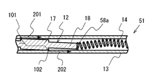
図1は第1の実施形態におけるコンタクトプローブの主要部を示す断面図、図2はプランジャーの主要部を示す部分拡大断面図、図3はスプリングと当接するプランジャーの端部を示す部分拡大断面図、図4はプランジャーを偏芯させた状態を示す部分拡大断面図、図5は、第1の実施形態におけるコンタクトプローブの接触抵抗値を示す表である。図1に示すように、本実施形態におけるコンタクトプローブ11は筒状体からなるバレル13と、
バレル13内に摺動自在に嵌合するプランジャー12と、バレル13内に配置されプランジャー12を軸方向に付勢するスプリング14とを備えており、いずれも導電性材料からなる。
(First embodiment)
1 is a cross-sectional view showing the main part of the contact probe in the first embodiment, FIG. 2 is a partially enlarged cross-sectional view showing the main part of the plunger, and FIG. 3 is a partial enlarged view showing the end of the plunger in contact with the spring. Sectional drawing, FIG. 4 is a partial enlarged sectional view showing a state where the plunger is eccentric, and FIG. 5 is a table showing contact resistance values of the contact probe in the first embodiment. As shown in FIG. 1, the contact probe 11 in this embodiment includes a barrel 13 made of a cylindrical body,
A plunger 12 slidably fitted in the barrel 13 and a spring 14 disposed in the barrel 13 for urging the plunger 12 in the axial direction are provided, both of which are made of a conductive material.

プランジャー12は径小部18と、径小部18に連結する径大部17と、径大部17に連結する接触部15とを備えており、径小部18の外径は径大部17の外径に比較して小さい値に設定されている。また、プランジャー12の接触部15と径大部17との間には、他部より径が細い細径領域16が設けられ、更に細径領域16と径大部17との境界には段部17aが形成されている。また、プランジャー12の接触部15側がバレル13の開口されている一端から突出し、その先端(図示せず)が被測定物に当接するようになっている。さらに、径小部18側がバレル13内に挿入された状態で径小部18の端部18aがスプリング14の一方の端部に当接されているとともに径小部18の端部18aを押圧している。   The plunger 12 includes a small diameter portion 18, a large diameter portion 17 connected to the small diameter portion 18, and a contact portion 15 connected to the large diameter portion 17, and the outer diameter of the small diameter portion 18 is the large diameter portion. The outer diameter of 17 is set to a small value. Further, between the contact portion 15 of the plunger 12 and the large-diameter portion 17, a narrow-diameter region 16 having a smaller diameter than the other portions is provided, and a step is formed at the boundary between the small-diameter region 16 and the large-diameter portion 17. A portion 17a is formed. Further, the contact portion 15 side of the plunger 12 protrudes from one end where the barrel 13 is opened, and its tip (not shown) comes into contact with the object to be measured. Further, with the small diameter portion 18 side inserted into the barrel 13, the end portion 18 a of the small diameter portion 18 is in contact with one end portion of the spring 14 and presses the end portion 18 a of the small diameter portion 18. ing.

一方バレル13の他端(図示せず)は、かしめられてスプリング14の他方の端部(図示せず)が当接して外部に押出されないようにされている。また、バレル13の内周部には周方向に延びる凸部からなる窪み13aがプランジャー12の細径領域16に遊嵌する様に設けられている。これによって、窪み13bと段部17aとが当接してプランジャー12がバレル13から外れるのを防止し、段部17aがバレル13の窪み13bと当接してプランジャー12の可動範囲を規制するとともに軸方向に移動自在に保持している。なお、本実施形態におけるバレル13は金(Au)、プラチナ(Pt)、パラジウム(Pd)を含んで成る導電性合金によって形成されている。   On the other hand, the other end (not shown) of the barrel 13 is caulked so that the other end (not shown) of the spring 14 comes into contact with it and is not pushed out. Further, a recess 13 a made up of a convex portion extending in the circumferential direction is provided in the inner peripheral portion of the barrel 13 so as to be loosely fitted in the small diameter region 16 of the plunger 12. As a result, the depression 13b and the stepped portion 17a abut against the plunger 12 from the barrel 13, and the stepped portion 17a abuts against the depression 13b of the barrel 13 to regulate the movable range of the plunger 12. It is held movably in the axial direction. In this embodiment, the barrel 13 is formed of a conductive alloy containing gold (Au), platinum (Pt), and palladium (Pd).

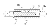
図2は図1の主要部を拡大した部分拡大断面を示している。図2に示すように、径小部18の外径bの値は径大部17の外径dの値と比較して小さい値に設定されている。また、バレル13の内径aと径大部17の外径dと隙間はプランジャー12がバレル13内の摺動を円滑に案内するために所定のクリアランスが確保されるように、その値が設定されている。これに対して径小部18の外周部18bとバレル13の内周部13aとの隙間19は、バレル13の内径aと径大部17の外径dと隙間より大きい値に設定されており、この隙間19にプランジャー12の摺動に伴い発生する摺動カスを収納するようになっている。   FIG. 2 shows a partially enlarged cross-sectional view in which the main part of FIG. 1 is enlarged. As shown in FIG. 2, the value of the outer diameter b of the small diameter portion 18 is set to a smaller value than the value of the outer diameter d of the large diameter portion 17. Further, the inner diameter a of the barrel 13 and the outer diameter d of the large diameter portion 17 and the gap are set so that a predetermined clearance is secured for the plunger 12 to smoothly guide the sliding in the barrel 13. Has been. In contrast, the gap 19 between the outer peripheral portion 18b of the small diameter portion 18 and the inner peripheral portion 13a of the barrel 13 is set to a value larger than the clearance between the inner diameter a of the barrel 13 and the outer diameter d of the large diameter portion 17. In this gap 19, sliding waste generated as the plunger 12 slides is stored.

図3は図1のプランジャー12の径小部18の端部18a付近を拡大した部分拡大断面を示している。図3に示すように径小部18の外径bはスプリング14の内径cに対して大きい値に設定されている。また、径小部18の端部18aは略円錐形形状をなし、その断面形状における頂角の角度Pの値は120度から160度の範囲に設定することが好ましい。この頂角の角度が120度より小さいと端部18aがスプリング14の内部に奥深く入り込むためプランジャー12がスプリング14により付勢された際に径小部18の端部18aをバレル13の中心軸Mに対し矢印B、Cで示す方向に偏心させにくくなり、好ましくない。また、頂角の角度が160度より大きいと端部18aとスプリング14の端部とが滑り易く、互いの位置が不安定となり好ましくない。なお、本実施形態においては角度Pの値を140度に設定した。   FIG. 3 shows a partially enlarged section in which the vicinity of the end 18a of the small diameter portion 18 of the plunger 12 of FIG. 1 is enlarged. As shown in FIG. 3, the outer diameter b of the small diameter portion 18 is set to a larger value than the inner diameter c of the spring 14. The end 18a of the small diameter portion 18 has a substantially conical shape, and the value of the apex angle P in the cross-sectional shape is preferably set in the range of 120 degrees to 160 degrees. When the apex angle is smaller than 120 degrees, the end 18 a enters deeply into the spring 14, so that when the plunger 12 is urged by the spring 14, the end 18 a of the small diameter portion 18 is moved to the central axis of the barrel 13. It becomes difficult to decenter in the directions indicated by arrows B and C with respect to M, which is not preferable. On the other hand, if the apex angle is larger than 160 degrees, the end portion 18a and the end portion of the spring 14 are easily slipped, and the mutual positions become unstable. In the present embodiment, the value of the angle P is set to 140 degrees.

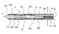
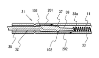
図4はコンタクトプローブ11の主要部を示す部分断面図で、プランジャー12が被測定物に押圧された際、スプリング14の付勢力に抗してプランジャー12がバレル13の内部に押し込まれた状態を示している。図4に示すように、コンタクトプローブ11は、プランジャー12をバレル13の内周部に接触させるために、プランジャー12の径小部18の端部18aは略円錐形形状に形成されている。プランジャー12にはスプリング14の付勢力により、バレル13の中心軸Mに直交する方向(矢印B、Cで示す方向)に押圧力が加えられ、プランジャー12の径小部18の端部18aがバレル13の中心軸に対し偏心することになる。このとき、径大部17も傾き、径大部17の外周部の一部がバレル13の内周部13aに接触し、接点101、102でプランジャー12がバレル13に当接し電気的に接触する。この場合の導通経路は接点101、102を通り矢印201、202で示す二つの導通経路となる。さらに、接触部15も傾き、接触部15の外周部の一部がバレル13の内周部13aに接触し、接点103、104でプランジャー12がバレル13に当接し電気的に接触する。この場合の導通経路は接点103、104を通り矢印203、204で示す二つの導通経路となる。   FIG. 4 is a partial cross-sectional view showing the main part of the contact probe 11. When the plunger 12 is pressed against the object to be measured, the plunger 12 is pushed into the barrel 13 against the urging force of the spring 14. Indicates the state. As shown in FIG. 4, in the contact probe 11, the end portion 18 a of the small diameter portion 18 of the plunger 12 is formed in a substantially conical shape in order to bring the plunger 12 into contact with the inner peripheral portion of the barrel 13. . Due to the urging force of the spring 14, a pressing force is applied to the plunger 12 in a direction perpendicular to the central axis M of the barrel 13 (directions indicated by arrows B and C), and the end portion 18 a of the small diameter portion 18 of the plunger 12. Is eccentric with respect to the central axis of the barrel 13. At this time, the large-diameter portion 17 is also inclined, a part of the outer peripheral portion of the large-diameter portion 17 comes into contact with the inner peripheral portion 13a of the barrel 13, and the plunger 12 comes into contact with and electrically contacts the barrel 13 at the contacts 101 and 102. To do. In this case, the conduction paths are two conduction paths indicated by arrows 201 and 202 through the contacts 101 and 102. Further, the contact portion 15 is also tilted, a part of the outer peripheral portion of the contact portion 15 comes into contact with the inner peripheral portion 13a of the barrel 13, and the plunger 12 comes into contact with the barrel 13 at the contact points 103 and 104 to make electrical contact. In this case, the conduction paths are two conduction paths indicated by arrows 203 and 204 through the contacts 103 and 104.

以上のように、本実施形態におけるコンタクトプローブ11は、被測定物に接触部15を当接させると、当接力を調節するために、プランジャー12がバレル13内を径大部17にガイドされ摺動しながら矢印Aに示す方向に移動する。この際、プランジャー12の摺動により摺動カスが発生するが、摺動カスはバレル13の内周部13aとプランジャー12の径小部18の外周部18bとの隙間19における径小部18の端部18aの近傍に収納される。この摺動カスを収納する位置は径大部17の外周部の一部がバレル13の内周部に接触させて導通経路202を形成する接点102と互いに離間した位置にあるため摺動カスによる接触不良が防止され、径大部17の外周部とバレル13の内周部とを接触を確実にすることが出来る。   As described above, in the contact probe 11 according to this embodiment, when the contact portion 15 is brought into contact with the object to be measured, the plunger 12 is guided inside the barrel 13 by the large diameter portion 17 in order to adjust the contact force. It moves in the direction shown by arrow A while sliding. At this time, sliding debris is generated by the sliding of the plunger 12, and the sliding debris is a small diameter portion in the gap 19 between the inner peripheral portion 13 a of the barrel 13 and the outer peripheral portion 18 b of the small diameter portion 18 of the plunger 12. 18 is housed in the vicinity of the end 18a. The sliding debris is stored at a position where a part of the outer peripheral portion of the large-diameter portion 17 is in contact with the inner peripheral portion of the barrel 13 and is separated from the contact 102 that forms the conduction path 202. Contact failure is prevented, and contact between the outer peripheral portion of the large diameter portion 17 and the inner peripheral portion of the barrel 13 can be ensured.

次に本実施形態におけるコンタクトプローブ11の耐久試験の結果について説明する。
図5(a)は、本実施形態におけるコンタクトプローブ11の耐久試験の結果を示し、図5(b)は比較のために従来例におけるコンタクトプローブの耐久試験の結果を示す。本実施形態におけるバレル13は従来例におけるコンタクトプローブは、プランジャーの形状が本実施形態と異なり、径小部18が形成されていないものである。その他は、ほぼ同様である。また、耐久試験はプランジャーをバレル内で30万回繰り返し摺動させた後の接触抵抗値を測定したものである。また、サンプル数は5個とした。図5(a)に示すように本実施形態におけるコンタクトプローブ11の耐久試験後の接触抵抗値(サンプル5個の平均値)は、447.7mΩと非常に小さく、また、ばらつきの範囲も103.3mΩと非常小さく安定した結果得られた。
Next, the result of the durability test of the contact probe 11 in the present embodiment will be described.
FIG. 5A shows the result of the endurance test of the contact probe 11 in this embodiment, and FIG. 5B shows the result of the endurance test of the contact probe in the conventional example for comparison. The barrel 13 in the present embodiment is a contact probe in the conventional example, which is different from the present embodiment in the shape of the plunger and in which the small diameter portion 18 is not formed. Others are almost the same. The durability test is a measurement of the contact resistance value after sliding the plunger repeatedly within the barrel 300,000 times. The number of samples was 5. As shown in FIG. 5A, the contact resistance value (average value of five samples) after the endurance test of the contact probe 11 in this embodiment is very small, 447.7 mΩ, and the range of variation is 103. The result was very small and stable, 3 mΩ.

これに対して、従来例におけるコンタクトプローブの耐久試験の結果は、図5(b)に示すように、接触抵抗値(サンプル5個の平均値)は、2467.8mΩと非常に大きく、また、ばらつきの範囲も2230.6mΩと非常に大きく不安定な結果得られた。このように、本実施形態におけるコンタクトプローブ11の耐久試験後の接触抵抗値は従来例に比較して約1/5に低減し、ばらつきの範囲を1/20に低減することができた。
以上のように本実施形態のコンタクトプローブ11は、プランジャー12の径小部18とバレル13の内周部13aとの間に形成する隙間19に、プランジャー12の摺動に伴い生ずる摺動カスを収納することにより、摺動カスによる接触不良を防止し、径大部17の外周部とバレルの内周部との接触点101、102における電気的な接触を確実にすることが出来る。
On the other hand, as shown in FIG. 5B, the result of the durability test of the contact probe in the conventional example is that the contact resistance value (average value of five samples) is 2467.8 mΩ, which is very large. The range of variation was 2230.6 mΩ, which was very large and unstable. Thus, the contact resistance value after the endurance test of the contact probe 11 in this embodiment was reduced to about 1/5 compared to the conventional example, and the range of variation could be reduced to 1/20.
As described above, the contact probe 11 according to the present embodiment slides in accordance with the sliding of the plunger 12 in the gap 19 formed between the small diameter portion 18 of the plunger 12 and the inner peripheral portion 13a of the barrel 13. By storing the residue, contact failure due to sliding residue can be prevented, and electrical contact at the contact points 101 and 102 between the outer peripheral portion of the large diameter portion 17 and the inner peripheral portion of the barrel can be ensured.

(第2の実施形態)
図6は第2の実施形態におけるコンタクトプローブの主要部を示す断面図、図7はプランジャーの主要部を示す部分拡大断面図、図8はスプリングと当接するプランジャーの端部を示す部分拡大断面図、図9はプランジャーを偏芯させた状態を示す部分拡大断面図である。図6に示すように、本実施形態におけるコンタクトプローブ21は筒状体からなるバレル23と、
バレル23内に摺動自在に嵌合するプランジャー22と、バレル23内に配置されプランジャー22を軸方向に付勢するスプリング14とを備えており、いずれも導電性材料からなる。
(Second Embodiment)
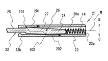
6 is a cross-sectional view showing the main part of the contact probe according to the second embodiment, FIG. 7 is a partial enlarged cross-sectional view showing the main part of the plunger, and FIG. 8 is a partial enlarged view showing the end of the plunger in contact with the spring. Sectional drawing and FIG. 9 are partial expanded sectional views which show the state which made the plunger eccentric. As shown in FIG. 6, the contact probe 21 in this embodiment includes a barrel 23 made of a cylindrical body,
A plunger 22 that is slidably fitted in the barrel 23 and a spring 14 that is disposed in the barrel 23 and urges the plunger 22 in the axial direction are provided, both of which are made of a conductive material.

プランジャー22は径小部28と、径小部28に連結する径大部27と、径大部27に連結する接触部25とを備えている。径小部28の径大部27との境界26における外径は径大部27の外径と同じ値に設定されており、径小部18の端部28aの外径は径大部17の外径に比較して小さい値に設定されている。さらに、径小部28は境界26からスプリング14に当接する端部28aに向かって外径が小さくなる略円錐台形形状をなしている。また、プランジャー22の接触部25と径大部27との境界には段部27aが形成されており、プランジャー22の接触部25側がバレル23の開口されている一端から突出し、その先端(図示せず)が被測定物に当接するようになっている。さらに、径小部28側がバレル23内に挿入された状態で径小部28の端部28aがスプリング14の一方の端部に当接されているとともに径小部28の端部28aを押圧している。   The plunger 22 includes a small diameter portion 28, a large diameter portion 27 connected to the small diameter portion 28, and a contact portion 25 connected to the large diameter portion 27. The outer diameter at the boundary 26 between the small diameter portion 28 and the large diameter portion 27 is set to the same value as the outer diameter of the large diameter portion 27, and the outer diameter of the end portion 28 a of the small diameter portion 18 is that of the large diameter portion 17. The value is set smaller than the outer diameter. Further, the small-diameter portion 28 has a substantially frustoconical shape whose outer diameter decreases from the boundary 26 toward the end portion 28 a that contacts the spring 14. Further, a stepped portion 27a is formed at the boundary between the contact portion 25 and the large diameter portion 27 of the plunger 22, and the contact portion 25 side of the plunger 22 protrudes from one end where the barrel 23 is opened, and the tip ( (Not shown) comes into contact with the object to be measured. Further, the end portion 28a of the small diameter portion 28 is in contact with one end portion of the spring 14 in a state where the small diameter portion 28 side is inserted into the barrel 23, and the end portion 28a of the small diameter portion 28 is pressed. ing.

一方バレル23の他端(図示せず)は、かしめられてスプリング14の他方の端部(図示せず)が当接して外部に押出されないようにされている。また、バレル23の開口されている一端には全周に亘って内側に向かって突出する鍔部23bがプランジャー12の接触部25に遊嵌する様に設けられている。これによって、鍔部23bと段部27aとが当接してプランジャー22がバレル23から外れるのを防止し、段部27aがバレル23の鍔部23bと当接してプランジャー22の可動範囲を規制するとともに軸方向に移動自在に保持している。なお、本実施形態におけるバレル23は、ニッケル材を主成分とする電気鋳造法により形成したものであり、内側に導電材料として金(Au)、外側にニッケル(Ni)とした構造である。電気鋳造法によれば、径の小さい超小型のバレルが高精度で製作可能であり、現在その外径が20μm程度まで製作可能である。   On the other hand, the other end (not shown) of the barrel 23 is caulked so that the other end (not shown) of the spring 14 abuts and is not pushed out. Further, a flange portion 23 b that protrudes inward over the entire circumference is provided at one end of the barrel 23 that is open so as to be loosely fitted to the contact portion 25 of the plunger 12. This prevents the flange portion 23b and the step portion 27a from coming into contact with each other to prevent the plunger 22 from coming off the barrel 23, and the step portion 27a comes into contact with the flange portion 23b in the barrel 23 to restrict the movable range of the plunger 22. And is held movably in the axial direction. The barrel 23 in the present embodiment is formed by an electroforming method having a nickel material as a main component, and has a structure in which gold (Au) is used as a conductive material on the inside and nickel (Ni) is used on the outside. According to the electrocasting method, an ultra-compact barrel with a small diameter can be manufactured with high accuracy, and the outer diameter can be manufactured up to about 20 μm at present.

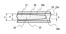
図7は図6の主要部を拡大した部分拡大断面を示している。図7に示すように、径小部28の端部28aの外径bの値は径大部27の外径dの値と比較して小さい値に設定されている。また、バレル23の内径aと径大部27の外径dと隙間はプランジャー22がバレル23内の摺動を円滑に案内するために所定のクリアランスが確保されるように、その値が設定されている。これに対して略円錐台形形状をなす径小部28の外周部28bとバレル23の内周部23aとの隙間は径小部28の端部28a付近で最大となり、この端部28a付近の隙間29がバレル23の内径aと径大部17の外径dと隙間より大きい値に設定されており、この隙間29にプランジャー22の摺動に伴い発生する摺動カスを収納するようになっている。   FIG. 7 shows a partially enlarged cross-sectional view in which the main part of FIG. 6 is enlarged. As shown in FIG. 7, the value of the outer diameter b of the end portion 28 a of the small diameter portion 28 is set to be smaller than the value of the outer diameter d of the large diameter portion 27. Further, the inner diameter a of the barrel 23 and the outer diameter d of the large diameter portion 27 and the gap are set so that a predetermined clearance is secured for the plunger 22 to smoothly guide the sliding in the barrel 23. Has been. On the other hand, the gap between the outer peripheral portion 28b of the small-diameter portion 28 having a substantially truncated cone shape and the inner peripheral portion 23a of the barrel 23 is the maximum near the end portion 28a of the small-diameter portion 28, and the gap near the end portion 28a. 29 is set to a value larger than the inner diameter a of the barrel 23 and the outer diameter d of the large-diameter portion 17 and the gap. The gap 29 accommodates the sliding debris generated by the sliding of the plunger 22. ing.

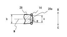
図8は図6のプランジャー22の径小部28の端部28a付近を拡大した部分拡大断面を示している。図8に示すように径小部28の端部28aの外径bはスプリング14の内径cに対して大きい値に設定されている。また、径小部28の端部28aは略半球状の形状をなし、その断面形状における円弧の半径Rの値は径小部28の端部28aの外径の1/2とした。なお、半径Rの値は特に限定されるものではないが、プランジャー22がスプリング14により付勢された際に径小部28の端部28aをバレル13の中心軸Mに対し矢印B、Cで示す方向に偏心させやすく、かつ端部28aとスプリング14の端部の互いの位置を安定させるためには、半径Rの値を端部28aの外径の1/2に近い値に設定することが好ましい。   FIG. 8 shows a partially enlarged section in which the vicinity of the end 28a of the small diameter portion 28 of the plunger 22 of FIG. 6 is enlarged. As shown in FIG. 8, the outer diameter b of the end portion 28 a of the small-diameter portion 28 is set to a larger value than the inner diameter c of the spring 14. The end portion 28a of the small-diameter portion 28 has a substantially hemispherical shape, and the value of the radius R of the arc in the cross-sectional shape is ½ of the outer diameter of the end portion 28a of the small-diameter portion 28. The value of the radius R is not particularly limited, but when the plunger 22 is urged by the spring 14, the end portion 28 a of the small diameter portion 28 is moved toward the center axis M of the barrel 13 by arrows B and C. The radius R is set to a value close to ½ of the outer diameter of the end portion 28a in order to be easily decentered in the direction indicated by the arrow and to stabilize the positions of the end portion 28a and the end portion of the spring 14. It is preferable.

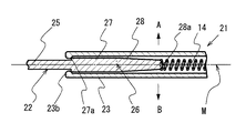
図9はコンタクトプローブ21の主要部を示す部分断面図で、プランジャー22が被測定物に押圧された際、スプリング14の付勢力に抗してプランジャー22がバレル23の内部に押し込まれた状態を示している。図9に示すように、コンタクトプローブ21は、プランジャー22をバレル23の内周部に接触させるために、プランジャー22の径小部28の端部28aは略半球状の形状に形成されている。プランジャー22はスプリング14の付勢力により、バレル23の中心軸Mに直交する方向(矢印B、Cで示す方向)に押圧力が加えられ、プランジャー22の径小部28の端部28aがバレル23の中心軸Mに対し偏心することになる。このとき、径大部27も傾き、径大部27の外周部の一部がバレル23の内周部23aに接触し、接点101、102でプランジャー22がバレル23に当接し電気的に接触する。この場合の導通経路は接点101、102を通り矢印201、202で示す二つの導通経路となる。   FIG. 9 is a partial cross-sectional view showing the main part of the contact probe 21. When the plunger 22 is pressed against the object to be measured, the plunger 22 is pushed into the barrel 23 against the urging force of the spring 14. Indicates the state. As shown in FIG. 9, in the contact probe 21, the end portion 28a of the small diameter portion 28 of the plunger 22 is formed in a substantially hemispherical shape so that the plunger 22 is brought into contact with the inner peripheral portion of the barrel 23. Yes. The plunger 22 is pressed by a biasing force of the spring 14 in a direction perpendicular to the central axis M of the barrel 23 (directions indicated by arrows B and C), and the end portion 28a of the small diameter portion 28 of the plunger 22 is It is eccentric with respect to the central axis M of the barrel 23. At this time, the large-diameter portion 27 is also inclined, a part of the outer peripheral portion of the large-diameter portion 27 comes into contact with the inner peripheral portion 23a of the barrel 23, and the plunger 22 comes into contact with and electrically contacts the barrel 23 at the contacts 101 and 102. To do. In this case, the conduction paths are two conduction paths indicated by arrows 201 and 202 through the contacts 101 and 102.

以上のように、本実施形態におけるコンタクトプローブ21は、プランジャー22の摺動により発生する摺動カスがバレル23の内周部23aとプランジャー22の径小部28の外周部28bとの端部28a付近の隙間29に収納される。したがって、第1の実施形態と同様に摺動カスによる接触不良が防止され、径大部27の外周部とバレル23の内周部23aとの接触を確実にすることが出来る。また、本実施形態のコンタクトプローブ21は径小部28が径大部27との境界26からスプリング14に当接する端部28aに向かって外径が小さくなる略円錐台形形状をなしているため強度的に優れており小型化に適した構造である。   As described above, in the contact probe 21 in the present embodiment, the sliding residue generated by the sliding of the plunger 22 is the end of the inner peripheral portion 23 a of the barrel 23 and the outer peripheral portion 28 b of the small diameter portion 28 of the plunger 22. It is stored in the gap 29 near the portion 28a. Therefore, the contact failure due to the sliding residue is prevented as in the first embodiment, and the contact between the outer peripheral portion of the large diameter portion 27 and the inner peripheral portion 23a of the barrel 23 can be ensured. Further, the contact probe 21 of this embodiment has a substantially truncated cone shape in which the outer diameter decreases from the boundary 26 between the small diameter portion 28 and the large diameter portion 27 toward the end portion 28a that contacts the spring 14. It is excellent in structure and suitable for downsizing.

本実施形態におけるコンタクトプローブ21の耐久試験後の接触抵抗値は第1の実施形態の場合と同様に、従来例に比較して約1/5に低減し、ばらつきの範囲を1/20に低減することができた。以上のように本実施形態のコンタクトプローブ21は、第1の実施形態と同様に、摺動カスによる接触不良を防止し、径大部27の外周部とバレル23の内周部との接触点101、102における電気的な接触を確実にすることが出来る。   The contact resistance value after the durability test of the contact probe 21 in this embodiment is reduced to about 1/5 compared to the conventional example, and the range of variation is reduced to 1/20, as in the first embodiment. We were able to. As described above, the contact probe 21 according to the present embodiment prevents contact failure due to sliding residue as in the first embodiment, and the contact point between the outer peripheral portion of the large diameter portion 27 and the inner peripheral portion of the barrel 23. Electrical contact at 101 and 102 can be ensured.

(第3の実施形態)
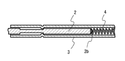
図10は第3の実施形態におけるコンタクトプローブの主要部を示す断面図、図11はプランジャーの主要部を示す部分拡大断面図、図12はスプリングと当接するプランジャーの端部を示す部分拡大断面図、図13はプランジャーを偏芯させた状態を示す部分拡大断面図である。図10に示すように、本実施形態におけるコンタクトプローブ31は筒状体からなるバレル33と、
バレル33内に摺動自在に嵌合するプランジャー32と、バレル23内に配置されプランジャー32を軸方向に付勢するスプリング14とを備えており、いずれも導電性材料からなる。
(Third embodiment)
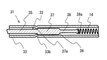
FIG. 10 is a cross-sectional view showing the main part of the contact probe in the third embodiment, FIG. 11 is a partial enlarged cross-sectional view showing the main part of the plunger, and FIG. 12 is a partial enlarged view showing the end of the plunger that contacts the spring. Sectional drawing and FIG. 13 are partial expanded sectional views which show the state which made the plunger eccentric. As shown in FIG. 10, the contact probe 31 in this embodiment includes a barrel 33 made of a cylindrical body,
A plunger 32 slidably fitted in the barrel 33 and a spring 14 disposed in the barrel 23 for urging the plunger 32 in the axial direction are provided, both of which are made of a conductive material.

プランジャー32は径小部38と、径小部38に連結する径大部37と、径大部37に連結する接触部35とを備えており、径小部38の外径は径大部37の外径に比較して小さい値に設定されている。また、プランジャー32の接触部35と径大部37との境界には段部37aが形成されている。また、プランジャー32の接触部35側がバレル33の開口されている一端から突出し、その先端(図示せず)が被測定物に当接するようになっている。さらに、径小部38側がバレル33内に挿入された状態で径小部38の端部38aがスプリング14の一方の端部に当接されているとともに径小部38の端部38aを押圧している。   The plunger 32 includes a small-diameter portion 38, a large-diameter portion 37 connected to the small-diameter portion 38, and a contact portion 35 connected to the large-diameter portion 37. The outer diameter of the small-diameter portion 38 is the large-diameter portion. The outer diameter of 37 is set to a small value. A step portion 37 a is formed at the boundary between the contact portion 35 and the large diameter portion 37 of the plunger 32. Further, the contact portion 35 side of the plunger 32 protrudes from one end where the barrel 33 is opened, and its tip (not shown) comes into contact with the object to be measured. Further, with the small diameter portion 38 side inserted into the barrel 33, the end portion 38a of the small diameter portion 38 is in contact with one end portion of the spring 14, and the end portion 38a of the small diameter portion 38 is pressed. ing.

一方バレル33の他端(図示せず)は、かしめられてスプリング14の他方の端部(図示せず)が当接して外部に押出されないようにされている。また、バレル33の内周部には周方向に延びる凸部からなる窪み33aがプランジャー32の接触部35に遊嵌する様に設けられている。これによって、窪み33aと段部37aとが当接してプランジャー32がバレル33から外れるのを防止し、段部37aがバレル33の窪み33aと当接してプランジャー32の可動範囲を規制するとともに軸方向に移動自在に保持している。なお、本実施形態におけるバレル33は、金(Au)、銀(Ag)、プラチナ(Pt)、ロジウム(Rh)を含んで成る導電性合金によって形成されている。   On the other hand, the other end (not shown) of the barrel 33 is caulked so that the other end (not shown) of the spring 14 abuts and is not pushed out. Further, a recess 33 a made of a convex portion extending in the circumferential direction is provided on the inner peripheral portion of the barrel 33 so as to be loosely fitted to the contact portion 35 of the plunger 32. Accordingly, the depression 33a and the stepped portion 37a abut against the plunger 32 from the barrel 33, and the stepped portion 37a abuts against the depression 33a of the barrel 33 to restrict the movable range of the plunger 32. It is held movably in the axial direction. The barrel 33 in the present embodiment is formed of a conductive alloy containing gold (Au), silver (Ag), platinum (Pt), and rhodium (Rh).

図11は図10の主要部を拡大した部分拡大断面を示している。図11に示すように、径小部38は、第1の径小部88aと第2の径小部88bとを有し、第1の径小部88aの外径eは第2の径小部88bの外径bと比較して小さい値に設定されており、第2の径小部88bはスプリング14側に位置するようになっている。第2の径小部88bの外径bの値は径大部37の外径dの値と比較して小さい値に設定されている。また、第1の径小部88aと径大部37との境界部は互いの外周部を接続するように斜面36が形成されている。この斜面36は外径の小さい第1の径小部88aと径大部37との境界部の機械的強度を補強するものであり、曲面であっても良い。   
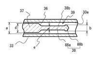
FIG. 11 shows a partially enlarged cross-sectional view in which the main part of FIG. 10 is enlarged. As shown in FIG. 11, the small-diameter portion 38 has a first small-diameter portion 88a and a second small-diameter portion 88b, and the outer diameter e of the first small-diameter portion 88a is the second small-diameter portion. It is set to a smaller value than the outer diameter b of the portion 88b, and the second small diameter portion 88b is positioned on the spring 14 side. The value of the outer diameter b of the second small diameter portion 88 b is set to be smaller than the value of the outer diameter d of the large diameter portion 37. In addition, a slope 36 is formed at the boundary between the first small diameter portion 88a and the large diameter portion 37 so as to connect the outer peripheral portions of each other. The slope 36 reinforces the mechanical strength of the boundary portion between the first small diameter portion 88a having a small outer diameter and the large diameter portion 37, and may be a curved surface.

また、バレル33の内径aと径大部17の外径dと隙間はプランジャー32がバレル33内の摺動を円滑に案内するために所定のクリアランスが確保されるように、その値が設定されている。これに対して径小部38の外周部38bとバレル33の内周部33aとの隙間39は、バレル33の内径aと径大部17の外径dと隙間より大きい値に設定されており、この隙間39にプランジャー32の摺動に伴い発生する摺動カスを収納するようになっている。また、第1の径小部88aと第2の径小部88bとの境界部には段部が形成されているが、この境界部も斜面または曲面とすることでプランジャー32の機械的強度を補強することができる。   In addition, the inner diameter a of the barrel 33 and the outer diameter d of the large diameter portion 17 and the gap are set so that a predetermined clearance is secured for the plunger 32 to smoothly guide the sliding in the barrel 33. Has been. On the other hand, the gap 39 between the outer peripheral portion 38b of the small diameter portion 38 and the inner peripheral portion 33a of the barrel 33 is set to a value larger than the clearance between the inner diameter a of the barrel 33 and the outer diameter d of the large diameter portion 17. In this gap 39, sliding debris generated as the plunger 32 slides is accommodated. In addition, a step portion is formed at the boundary between the first small diameter portion 88a and the second small diameter portion 88b, and the mechanical strength of the plunger 32 is also made by making this boundary portion a slope or a curved surface. Can be reinforced.

図12は図10のプランジャー32の径小部38の端部38a付近を拡大した部分拡大断面を示している。図12に示すように第2の径小部88bの外径bはスプリング14の内径cに対して大きい値に設定されている。また、第2の径小部88bの端部である径小部38の端部38aは第1の実施形態と同様に略円錐形形状をなし、その断面形状における頂角の角度Pの値は120度に設定されている。   FIG. 12 shows a partially enlarged section in which the vicinity of the end 38a of the small diameter portion 38 of the plunger 32 of FIG. 10 is enlarged. As shown in FIG. 12, the outer diameter b of the second small diameter portion 88 b is set to a larger value than the inner diameter c of the spring 14. The end 38a of the small diameter portion 38, which is the end of the second small diameter portion 88b, has a substantially conical shape as in the first embodiment, and the value of the apex angle P in the cross-sectional shape is It is set to 120 degrees.

図13はコンタクトプローブ31の主要部を示す部分断面図で、プランジャー32が被測定物に押圧された際、スプリング14の付勢力に抗してプランジャー32がバレル33の内部に押し込まれた状態を示している。図13に示すように、コンタクトプローブ31は、プランジャー32をバレル33の内周部に接触させるために、プランジャー32の径小部38の端部38aは第1の実施形態と同様に略円錐形形状に形成されている。径小部38の端部38aはスプリング14の付勢力によりバレル33の中心軸に対し偏心し、径大部37が傾き、径大部37の外周部の一部がバレル33の内周部33aに接触する。このとき、接点101、102でプランジャー32がバレル33に当接し電気的に接触すし矢印201、202で示す二つの導通経路が形成される。   FIG. 13 is a partial cross-sectional view showing the main part of the contact probe 31. When the plunger 32 is pressed against the object to be measured, the plunger 32 is pushed into the barrel 33 against the urging force of the spring 14. Indicates the state. As shown in FIG. 13, since the contact probe 31 brings the plunger 32 into contact with the inner peripheral portion of the barrel 33, the end 38a of the small diameter portion 38 of the plunger 32 is substantially the same as in the first embodiment. It is formed in a conical shape. The end 38 a of the small diameter portion 38 is eccentric with respect to the central axis of the barrel 33 by the urging force of the spring 14, the large diameter portion 37 is inclined, and a part of the outer peripheral portion of the large diameter portion 37 is the inner peripheral portion 33 a of the barrel 33. To touch. At this time, the contact points 101 and 102 cause the plunger 32 to come into contact with and electrically contact the barrel 33, and two conduction paths indicated by arrows 201 and 202 are formed.

以上のように、本実施形態におけるコンタクトプローブ31は、プランジャー32の摺動により発生する摺動カスがバレル33の内周部33aとプランジャー32の径小部38の外周部38bとの隙間39に収納される。これによって、第1の実施形態と同様に摺動カスによる接触不良が防止され、径大部37の外周部とバレル33の内周部33aとの接触を確実にすることが出来る。また、本実施形態のコンタクトプローブ31は第1の径小部88aの外径e値が第2の径小部88bの外径bの値bより小さく隙間39の容積が大きいため発生する摺動カスを収納する容積を大きくすることができる。これによって径大部37の外周部とバレル33の内周部33aとの接触をより確実にすることが出来る。   As described above, in the contact probe 31 according to this embodiment, the sliding residue generated by the sliding of the plunger 32 is a gap between the inner peripheral portion 33a of the barrel 33 and the outer peripheral portion 38b of the small diameter portion 38 of the plunger 32. 39. As a result, similar to the first embodiment, contact failure due to sliding residue is prevented, and contact between the outer peripheral portion of the large diameter portion 37 and the inner peripheral portion 33a of the barrel 33 can be ensured. Further, in the contact probe 31 of the present embodiment, sliding that occurs because the outer diameter e value of the first small diameter portion 88a is smaller than the value b of the outer diameter b of the second small diameter portion 88b and the volume of the gap 39 is large. The volume for storing waste can be increased. Thereby, the contact between the outer peripheral portion of the large-diameter portion 37 and the inner peripheral portion 33a of the barrel 33 can be further ensured.

本実施形態におけるコンタクトプローブ31の耐久試験後の接触抵抗値は第1の実施形態の場合と同様に、従来例に比較して約1/5に低減し、ばらつきの範囲は1/20に低減することができた。以上のように本実施形態のコンタクトプローブ31は、第1の実施形態と同様に、摺動カスによる接触不良を防止し、径大部37の外周部とバレル33の内周部33aとの接触点101、102における電気的な接触を確実にすることが出来る。   As in the first embodiment, the contact resistance value after the endurance test of the contact probe 31 in this embodiment is reduced to about 1/5 compared to the conventional example, and the range of variation is reduced to 1/20. We were able to. As described above, the contact probe 31 according to the present embodiment prevents contact failure due to sliding residue as in the first embodiment, and contacts the outer peripheral portion of the large diameter portion 37 and the inner peripheral portion 33a of the barrel 33. Electrical contact at the points 101 and 102 can be ensured.

(第4の実施形態)
図14は第4の実施形態におけるコンタクトプローブの主要部を示す断面図、図15はスプリングと当接するプランジャーの端部を示す部分拡大断面図、図16はプランジャーを偏芯させた状態を示す部分拡大断面図である。図14に示すように、本実施形態におけるコンタクトプローブ41はバレル43と、
プランジャー42と、スプリング14とを備えており、プランジャー42の形状が第1の実施形態と異なり、バレル43は第2の実施形態のバレル23と同様にニッケル材を主成分とする電気鋳造法により形成したものである。その他は第1の実施形態とほぼ同様である。
(Fourth embodiment)
FIG. 14 is a cross-sectional view showing the main part of the contact probe in the fourth embodiment, FIG. 15 is a partially enlarged cross-sectional view showing the end of the plunger in contact with the spring, and FIG. 16 shows a state where the plunger is eccentric. It is a partial expanded sectional view shown. As shown in FIG. 14, the contact probe 41 in this embodiment includes a barrel 43,
A plunger 42 and a spring 14 are provided, and the shape of the plunger 42 is different from that of the first embodiment, and the barrel 43 is an electroforming mainly composed of a nickel material, like the barrel 23 of the second embodiment. It is formed by the law. The rest is almost the same as in the first embodiment.

プランジャー42は径小部48と、径小部48に連結する径大部47と、径大部47に連結する接触部45とを備えており、径小部48の外径は径大部47の外径に比較して小さい値に設定されている。なおバレル43は外径が800μmで、その大きさが第1の実施形態と異なるが、その他の形状については、ほぼ同様である。また、プランジャー42とバレル43との配置状態についても第1の実施形態と同様であるため説明は省略する。   The plunger 42 includes a small-diameter portion 48, a large-diameter portion 47 that is connected to the small-diameter portion 48, and a contact portion 45 that is connected to the large-diameter portion 47. The outer diameter of the small-diameter portion 48 is the large-diameter portion. The outer diameter of 47 is set to a small value. The barrel 43 has an outer diameter of 800 μm and the size is different from that of the first embodiment, but the other shapes are almost the same. Moreover, since the arrangement state of the plunger 42 and the barrel 43 is the same as that of the first embodiment, the description thereof is omitted.

図15は図14の主要部を拡大した部分拡大断面を示している。図15に示すように、径小部48は、径大部47と径小部48との境界46を基点として径小部48の中心を通る径小部中心軸線Nが径大部47の中心を通る径大部中心軸線Mに対して所定の傾斜角度Qで傾斜するように屈曲されている。境界46には段部が形成されているが、この段部に代えて斜面または曲面としてもよく、これによってプランジャー42の機械的強度を補強することができる。   FIG. 15 shows a partially enlarged cross-sectional view in which the main part of FIG. 14 is enlarged. As shown in FIG. 15, the small-diameter portion 48 has a small-diameter central axis N passing through the center of the small-diameter portion 48 with the boundary 46 between the large-diameter portion 47 and the small-diameter portion 48 as a base point. Is bent so as to incline at a predetermined inclination angle Q with respect to the large-diameter central axis M passing through. A step portion is formed at the boundary 46, but a slope or a curved surface may be used instead of the step portion, whereby the mechanical strength of the plunger 42 can be reinforced.

また、バレル43の内径aと径大部47の外径dと隙間はプランジャー42がバレル43内の摺動を円滑に案内するために所定のクリアランスが確保されるように、その値が設定されている。これに対して径小部48の外周部48bとバレル43の内周部43aとの隙間49は、バレル43の内径aと径大部47の外径dと隙間より大きい値に設定されており、この隙間49にプランジャー42の摺動に伴い発生する摺動カスを収納するようになっている。   Further, the inner diameter a of the barrel 43 and the outer diameter d of the large diameter portion 47 and the gap are set so that a predetermined clearance is ensured so that the plunger 42 smoothly guides the sliding in the barrel 43. Has been. On the other hand, the gap 49 between the outer peripheral portion 48b of the small diameter portion 48 and the inner peripheral portion 43a of the barrel 43 is set to a value larger than the clearance between the inner diameter a of the barrel 43 and the outer diameter d of the large diameter portion 47. In this gap 49, sliding debris generated as the plunger 42 slides is stored.

図16は図14のプランジャー42の径小部48の端部48a付近を拡大した部分拡大断面を示している。図16に示すように径小部48の外径bはスプリング14の内径cに対して大きい値に設定されている。また、径小部48の端部48aは第1の実施形態と同様に略円錐形形状をなし、その断面形状における頂角の角度Pの値は160度に設定されている。   FIG. 16 shows a partially enlarged section in which the vicinity of the end 48a of the small diameter portion 48 of the plunger 42 of FIG. 14 is enlarged. As shown in FIG. 16, the outer diameter b of the small diameter portion 48 is set to a larger value than the inner diameter c of the spring 14. Further, the end 48a of the small diameter portion 48 has a substantially conical shape as in the first embodiment, and the value of the apex angle P in the cross-sectional shape is set to 160 degrees.

図17はコンタクトプローブ41の主要部を示す部分断面図で、プランジャー42が被測定物に押圧された際、スプリング14の付勢力に抗してプランジャー42がバレル43の内部に押し込まれた状態を示している。図17に示すように、コンタクトプローブ41は、プランジャー42をバレル43の内周部に接触させるために、プランジャー42の径小部48の端部48aは第1の実施形態と同様に略円錐形形状に形成されている。径小部48の端部48aはスプリング14の付勢力によりバレル43の中心軸に対し偏心し、径大部47が傾き、径大部47の外周部の一部がバレル43の内周部43aに接触する。このとき、接点101、102でプランジャー42がバレル43に当接し、電気的に接触して矢印201、202で示す二つの導通経路が形成される。本実施形態における径小部48は、径大部47と径小部48との境界46を基点として所定の傾斜角度Qで傾斜するように屈曲しているためスプリング14の付勢力によりバレル43の中心軸に対し偏心し易くなっている。この傾斜角度Qの値は、特に限定されるものではなく、プランジャー42がスプリング14の付勢力により所望の値に偏心するよう適宜決めることができ、1度から3度の間であることが望ましい。なお、本実施形態においては、傾斜角度Qの値を約2度とした。   FIG. 17 is a partial cross-sectional view showing the main part of the contact probe 41. When the plunger 42 is pressed against the object to be measured, the plunger 42 is pushed into the barrel 43 against the urging force of the spring 14. Indicates the state. As shown in FIG. 17, since the contact probe 41 brings the plunger 42 into contact with the inner peripheral portion of the barrel 43, the end 48a of the small diameter portion 48 of the plunger 42 is substantially the same as in the first embodiment. It is formed in a conical shape. The end 48 a of the small diameter portion 48 is eccentric with respect to the central axis of the barrel 43 by the urging force of the spring 14, the large diameter portion 47 is inclined, and a part of the outer peripheral portion of the large diameter portion 47 is the inner peripheral portion 43 a of the barrel 43. To touch. At this time, the plunger 42 abuts on the barrel 43 at the contacts 101 and 102 and is electrically contacted to form two conduction paths indicated by arrows 201 and 202. In this embodiment, the small diameter portion 48 is bent so as to be inclined at a predetermined inclination angle Q with the boundary 46 between the large diameter portion 47 and the small diameter portion 48 as a base point. It is easy to be eccentric with respect to the central axis. The value of the inclination angle Q is not particularly limited, and can be determined as appropriate so that the plunger 42 is decentered to a desired value by the biasing force of the spring 14, and should be between 1 degree and 3 degrees. desirable. In the present embodiment, the value of the inclination angle Q is about 2 degrees.

以上のように、本実施形態におけるコンタクトプローブ41は、プランジャー42の摺動により発生する摺動カスがバレル43の内周部43aとプランジャー42の径小部48の外周部48bとの隙間49に収納される。これによって、第1の実施形態と同様に摺動カスによる接触不良が防止され、径大部47の外周部とバレル43の内周部43aとの接触を確実にすることが出来る。また、本実施形態のコンタクトプローブ41は径小部48との境界46を基点として屈曲しているためスプリング14の付勢力によりバレル43の中心軸に対し偏心し易く、径大部47の外周部とバレル43の内周部43aとの接触をより確実にすることが出来る。   As described above, in the contact probe 41 in the present embodiment, the sliding residue generated by the sliding of the plunger 42 is a gap between the inner peripheral portion 43a of the barrel 43 and the outer peripheral portion 48b of the small diameter portion 48 of the plunger 42. 49. As a result, similar to the first embodiment, contact failure due to sliding residue is prevented, and contact between the outer peripheral portion of the large diameter portion 47 and the inner peripheral portion 43a of the barrel 43 can be ensured. Further, since the contact probe 41 of this embodiment is bent with the boundary 46 with the small-diameter portion 48 as a base point, the contact probe 41 is easily decentered with respect to the central axis of the barrel 43 due to the urging force of the spring 14, and And the inner peripheral portion 43a of the barrel 43 can be made more reliable.

本実施形態におけるコンタクトプローブ41の耐久試験後の接触抵抗値は、第1の実施形態の場合と同様に、従来例に比較して約1/5に低減し、ばらつきの範囲は1/20程度に低減することができた。なお、本実施形態、従来例におけるバレルの外径の値は、共に800μmとした。以上のように本実施形態のコンタクトプローブ41は、第1の実施形態と同様に、摺動カスによる接触不良を防止し、径大部47の外周部とバレル43の内周部43aとの接触点101、102における電気的な接触を確実にすることが出来る。   As in the case of the first embodiment, the contact resistance value after the durability test of the contact probe 41 in the present embodiment is reduced to about 1/5 compared to the conventional example, and the range of variation is about 1/20. It was possible to reduce it. In this embodiment and the conventional example, the value of the outer diameter of the barrel is set to 800 μm. As described above, the contact probe 41 according to the present embodiment prevents contact failure due to sliding residue as in the first embodiment, and contacts the outer peripheral portion of the large-diameter portion 47 and the inner peripheral portion 43a of the barrel 43. Electrical contact at the points 101 and 102 can be ensured.

(第5の実施形態)
図18は第5の実施形態におけるプランジャーの主要部を示す断面図で、図19は第5の実施形態におけるコンタクトプローブの主要部を示す断面図で、プランジャーを偏芯させた状態を示す部分拡大断面図である。本実施形態におけるコンタクトプローブはプランジャーの端部の形状が第1の実施形態と異なる例であり、その他は第1の実施形態と同様である。そこで同じ構成要素については同一番号を付与し詳細な説明を省略する。
(Fifth embodiment)
FIG. 18 is a cross-sectional view showing the main part of the plunger in the fifth embodiment, and FIG. 19 is a cross-sectional view showing the main part of the contact probe in the fifth embodiment, showing a state where the plunger is eccentric. It is a partial expanded sectional view. The contact probe in the present embodiment is an example in which the shape of the end portion of the plunger is different from that in the first embodiment, and the others are the same as in the first embodiment. Therefore, the same components are assigned the same numbers, and detailed description thereof is omitted.

図18に示すように、コンタクトプローブ51は、プランジャー12の径小部18の端部58aが平面状に形成されており、この平面がプランジャー12の中心軸線に対して直交する方向に形成されている。また、図19はコンタクトプローブ51の主要部を示す部分断面図で、プランジャー12が被測定物に押圧された際、スプリング14の付勢力に抗してプランジャー12がバレル13の内部に押し込まれた状態を示している。図19に示すように本実施形態においては、プランジャー12がバレル13の内部に押し込まれた場合、端部58aが平面状に形成されているため、通常ではスプリング14の付勢力によりバレル13の中心軸と直交する方向の力を受けにくいが、スプリング14の線径を細くする等、ばね形状を工夫することによりスプリング14を屈曲させ、径小部18の端部58aをバレル13の中心軸に対し偏心させることができる。これによって径大部17が傾き、径大部17の外周部の一部がバレル13の内周部13aに接触し、第1の実施形態と同様に接点101、102を通る矢印201、202で示す二つの導通経路が形成される。   As shown in FIG. 18, in the contact probe 51, the end portion 58 a of the small diameter portion 18 of the plunger 12 is formed in a flat shape, and this flat surface is formed in a direction orthogonal to the central axis of the plunger 12. Has been. FIG. 19 is a partial cross-sectional view showing the main part of the contact probe 51. When the plunger 12 is pressed against the object to be measured, the plunger 12 is pushed into the barrel 13 against the biasing force of the spring 14. The state is shown. As shown in FIG. 19, in the present embodiment, when the plunger 12 is pushed into the barrel 13, the end portion 58 a is formed in a flat shape, so that the urging force of the spring 14 normally causes the barrel 13 to move. Although it is difficult to receive a force in a direction orthogonal to the central axis, the spring 14 is bent by devising the spring shape, for example, by reducing the wire diameter of the spring 14, and the end 58 a of the small diameter portion 18 is made to be the central axis of the barrel 13. Can be decentered. As a result, the large-diameter portion 17 is inclined, and a part of the outer peripheral portion of the large-diameter portion 17 comes into contact with the inner peripheral portion 13a of the barrel 13, and the arrows 201 and 202 passing through the contacts 101 and 102 are the same as in the first embodiment. The two conduction paths shown are formed.

以上のように、本実施形態におけるコンタクトプローブ51は、第1の実施形態と同様に摺動カスによる接触不良が防止され、電気的接触を確実にすることが出来る。なお、本実施形態におけるコンタクトプローブ51の耐久試験後の接触抵抗値は第1の実施形態と同様に、従来例に比較して約1/5に低減し、ばらつきの範囲は1/20程度に低減することができた。   As described above, the contact probe 51 in the present embodiment can prevent a contact failure due to sliding residue as in the first embodiment, and can ensure electrical contact. In addition, the contact resistance value after the durability test of the contact probe 51 in this embodiment is reduced to about 1/5 compared to the conventional example, and the range of variation is about 1/20, as in the first embodiment. It was possible to reduce.

図20、図21は、第5の実施形態におけるプランジャーの端部の他の例を示す。図20はプランジャーの主要部を示す断面図、図21はコンタクトプローブ61の主要部を示す部分断面図で、プランジャー12が被測定物に押圧された際、スプリング14の付勢力に抗してプランジャー12がバレル13の内部に押し込まれた状態を示す図である。図20に示すように、コンタクトプローブ61は、プランジャー12の径小部18の端部68aがプランジャー12の中心軸線に対して角度を有する斜面状に形成されている。このため図21に示すようにスプリング14の付勢力により、プランジャー12にバレル13の中心軸に直交する押圧力が加えられ、プランジャー12の端部68aをバレル3に対し偏心し、径大部17が傾き、径大部17の外周部の一部がバレル13の内周部13aに接触させ易くすることが出来る。これによって、電気的接触をより確実にすることが出来る。なお、本例におけるコンタクトプローブ61の耐久試験後の接触抵抗値は第1の実施形態と同様に、従来例に比較して約1/5に低減し、ばらつきの範囲は1/20程度に低減することができた。   20 and 21 show another example of the end of the plunger in the fifth embodiment. FIG. 20 is a cross-sectional view showing the main part of the plunger, and FIG. 21 is a partial cross-sectional view showing the main part of the contact probe 61, which resists the biasing force of the spring 14 when the plunger 12 is pressed against the object to be measured. FIG. 6 is a view showing a state where the plunger 12 is pushed into the barrel 13. As shown in FIG. 20, the contact probe 61 is formed in a slope shape in which the end 68 a of the small diameter portion 18 of the plunger 12 has an angle with respect to the central axis of the plunger 12. For this reason, as shown in FIG. 21, the urging force of the spring 14 applies a pressing force orthogonal to the central axis of the barrel 13 to the plunger 12, and the end portion 68a of the plunger 12 is eccentric with respect to the barrel 3 to increase the diameter. The portion 17 is inclined, and a part of the outer peripheral portion of the large diameter portion 17 can be easily brought into contact with the inner peripheral portion 13 a of the barrel 13. Thereby, electrical contact can be made more reliable. The contact resistance value after the durability test of the contact probe 61 in this example is reduced to about 1/5 compared to the conventional example, and the range of variation is reduced to about 1/20, as in the first embodiment. We were able to.

なお、本発明のコンタクトプローブにおいては、バレル外径については、800μm以上の場合にも耐久試験後の接触抵抗値を従来例と比較して小さくすることができるが、バレル外径が800μm以下で大きな効果が得られ、特に300μm以下の極小径の場合に顕著な効果が得られる。   In the contact probe of the present invention, the contact resistance value after the durability test can be reduced as compared with the conventional example even when the barrel outer diameter is 800 μm or more, but the barrel outer diameter is 800 μm or less. A large effect is obtained, and a remarkable effect is obtained particularly when the diameter is 300 μm or less.

また、各実施形態におけるプランジャー、スプリングについては、特に記載してないが従来と同様の材料を用いたものを採用した。   In addition, the plunger and the spring in each embodiment are not particularly described, but those using the same material as the conventional one are employed.

また、各実施形態におけるコンタクトプローブについては、片側可動タイプを例に説明したが、これに限定されるものではなく両側タイプの場合も同様な効果を得ることができる。   In addition, the contact probe in each embodiment has been described by taking the one-side movable type as an example. However, the contact probe is not limited to this, and the same effect can be obtained in the case of the both-side type.

本発明の第1の実施形態におけるコンタクトプローブの主要部を示す断面図である。It is sectional drawing which shows the principal part of the contact probe in the 1st Embodiment of this invention. 本発明の第1の実施形態におけるプランジャーの主要部を示す部分拡大断面図である。It is a partial expanded sectional view which shows the principal part of the plunger in the 1st Embodiment of this invention. 本発明の第1の実施形態におけるスプリングと当接するプランジャーの端部を示す部分拡大断面図である。It is a partial expanded sectional view which shows the edge part of the plunger contact | abutted with the spring in the 1st Embodiment of this invention. 図1におけるプランジャーを偏芯させた状態を示す部分拡大断面図である。It is a partial expanded sectional view which shows the state which made the plunger in FIG. 1 eccentric. 本発明の第1の実施形態における接触抵抗値を示す表である。It is a table | surface which shows the contact resistance value in the 1st Embodiment of this invention. 本発明の第2の実施形態におけるコンタクトプローブの主要部を示す断面図である。It is sectional drawing which shows the principal part of the contact probe in the 2nd Embodiment of this invention. 本発明の第2の実施形態におけるプランジャーの主要部を示す部分拡大断面図である。It is a partial expanded sectional view which shows the principal part of the plunger in the 2nd Embodiment of this invention. 本発明の第2の実施形態におけるスプリングと当接するプランジャーの端部を示す部分拡大断面図である。It is a partial expanded sectional view which shows the edge part of the plunger contact | abutted with the spring in the 2nd Embodiment of this invention. 図6におけるプランジャーを偏芯させた状態を示す部分拡大断面図である。It is a partial expanded sectional view which shows the state which made the plunger in FIG. 6 eccentric. 本発明の第3の実施形態におけるコンタクトプローブの主要部を示す断面図である。It is sectional drawing which shows the principal part of the contact probe in the 3rd Embodiment of this invention. 本発明の第3の実施形態におけるプランジャーの主要部を示す部分拡大断面図である。It is a partial expanded sectional view which shows the principal part of the plunger in the 3rd Embodiment of this invention. 本発明の第3の実施形態におけるスプリングと当接するプランジャーの端部を示す部分拡大断面図である。It is a partial expanded sectional view which shows the edge part of the plunger contact | abutted with the spring in the 3rd Embodiment of this invention. 図10におけるプランジャーを偏芯させた状態を示す部分拡大断面図である。It is a partial expanded sectional view which shows the state which made the plunger in FIG. 10 eccentric. 本発明の第4の実施形態におけるコンタクトプローブの主要部を示す断面図である。It is sectional drawing which shows the principal part of the contact probe in the 4th Embodiment of this invention. 本発明の第4の実施形態におけるプランジャーの主要部を示す部分拡大断面図である。It is a partial expanded sectional view which shows the principal part of the plunger in the 4th Embodiment of this invention. 本発明の第4の実施形態におけるスプリングと当接するプランジャーの端部を示す部分拡大断面図である。It is a partial expanded sectional view which shows the edge part of the plunger contact | abutted with the spring in the 4th Embodiment of this invention. 図14におけるプランジャーを偏芯させた状態を示す部分拡大断面図である。It is a partial expanded sectional view which shows the state which made the plunger in FIG. 14 eccentric. 本発明の第5の実施形態におけるプランジャーの主要部を示す断面図である。It is sectional drawing which shows the principal part of the plunger in the 5th Embodiment of this invention. 本発明の第5の実施形態におけるコンタクトプローブの主要部を示す図で、プランジャーを偏芯させた状態を示す部分拡大断面図である。It is a figure which shows the principal part of the contact probe in the 5th Embodiment of this invention, and is the elements on larger scale which show the state which made the plunger eccentric. 本発明の第5の実施形態におけるプランジャーの端部の他の例を示す断面図である。It is sectional drawing which shows the other example of the edge part of the plunger in the 5th Embodiment of this invention. 図20に示すプランジャーを搭載したコンタクトプローブの主要部を示す図で、プランジャーを偏芯させた状態を示す部分拡大断面図である。It is a figure which shows the principal part of the contact probe carrying the plunger shown in FIG. 20, and is the elements on larger scale which show the state which made the plunger eccentric. 従来技術におけるコンタクトプローブを示す外観図である。It is an external view which shows the contact probe in a prior art. 図22におけるA部の部分拡大断面図である。It is a partial expanded sectional view of the A section in FIG. 図23におけるプランジャーを偏芯させた状態を示す部分拡大断面図である。It is a partial expanded sectional view which shows the state which eccentrically placed the plunger in FIG.

符号の説明Explanation of symbols

11、21、31、41、51、61 コンタクトプローブ
12、22、32、42 プランジャー
13、23、33、43 バレル
13a、23a、33a、43a バレルの内周部
13b、33b、43b 窪み
14 スプリング
15、25、35、45 プランジャーの接触部
16 細径部
17、27、37、47 径大部
17a、27a、37a、47a 段部
18、28、38、48 径小部
18a、28a、38a、48a、58a、68a 径小部の端部
18b、28b、38b、48b 径小部の外周部
19、29、39、49 隙間
23b
26、46 境界
36 斜面
88a 第1の径小部
88b 第2の径小部
101、102、103 接点
202、202、203 導通径路
11, 21, 31, 41, 51, 61 Contact probe 12, 22, 32, 42 Plunger 13, 23, 33, 43 Barrel 13a, 23a, 33a, 43a Inner peripheral part of barrel 13b, 33b, 43b Depression 14 Spring
15, 25, 35, 45 Plunger contact portion 16 Small diameter portion 17, 27, 37, 47 Large diameter portion 17a, 27a, 37a, 47a Step portion 18, 28, 38, 48 Small diameter portion 18a, 28a, 38a 48a, 58a, 68a Small diameter end
18b, 28b, 38b, 48b Small diameter outer peripheral parts 19, 29, 39, 49 Clearance 23b
26, 46 border
36 slope 88a first small diameter portion
88b 2nd small diameter part 101,102,103 Contact 202,202,203 Conduction path

Claims (9)

導電性の筒状体からなるバレルと、 該バレル内に摺動自在に嵌合する導電性のプランジャーと、前記バレル内に配置され該プランジャーを軸方向に付勢するスプリングとを備え、前記プランジャーは前記スプリングにその端部を当接する径小部と、該径小部に連結する径大部とを有し、前記径小部の外径を前記径大部の外径と比較して小さい値に設定したことを特徴とするコンタクトプローブ。   A barrel made of a conductive cylindrical body, a conductive plunger slidably fitted in the barrel, and a spring disposed in the barrel and biasing the plunger in the axial direction, The plunger has a small-diameter portion that abuts the end of the spring and a large-diameter portion that is connected to the small-diameter portion, and compares the outer diameter of the small-diameter portion with the outer diameter of the large-diameter portion. The contact probe is characterized in that it is set to a small value. 前記プンジャーの径小部は前記径大部との境界から前記スプリングに当接する端部に向かって外径が小さくなる略円錐台形形状をなすことを特徴とする請求項1に記載のコンタクトプローブ。   2. The contact probe according to claim 1, wherein the small diameter portion of the Punger has a substantially frustoconical shape whose outer diameter decreases from a boundary with the large diameter portion toward an end contacting the spring. 前記プンジャーの径小部は第1の径小部と第2の径小部とを有し、該第1の径小部の外径は該第2の径小部の外径と比較して小さい値に設定され、且つ前記第2の径小部が前記スプリング側に位置することを特徴とする請求項1に記載のコンタクトプローブ。   The small diameter portion of the Punger has a first small diameter portion and a second small diameter portion, and the outer diameter of the first small diameter portion is compared with the outer diameter of the second small diameter portion. The contact probe according to claim 1, wherein the contact probe is set to a small value and the second small diameter portion is located on the spring side. 前記径小部は、その中心を通る径小部中心軸線が前記径大部の中心を通る径大部中心軸線に対して傾斜するように前記径大部と前記径小部との境界付近を基点として屈曲されていることを特徴とする請求項1に記載のコンタクトプローブ。   The small-diameter portion is located near the boundary between the large-diameter portion and the small-diameter portion so that the small-diameter central axis passing through the center thereof is inclined with respect to the large-diameter central axis passing through the center of the large-diameter portion. The contact probe according to claim 1, wherein the contact probe is bent as a base point. 前記径小部の前記スプリングに当接する端部が略円錐形形状をなし、その断面形状における頂角の角度が120度から160度の範囲に設定されていることを特徴とする請求項1から請求項4のいずれか1項に記載のコンタクトプローブ。   The end of the small-diameter portion that contacts the spring has a substantially conical shape, and the apex angle in the cross-sectional shape is set in a range of 120 degrees to 160 degrees. The contact probe according to claim 4. 前記径小部の前記スプリングに当接する端部が半球状の形状をなすことを特徴とする請求項1から請求項4のいずれか1項に記載のコンタクトプローブ。   The contact probe according to any one of claims 1 to 4, wherein an end portion of the small-diameter portion that contacts the spring has a hemispherical shape. 前記バレルが、Au、Ag、Pt、Pd、Rhの少なくとも一つの貴金属を10%以上含んで成る導電性合金によって形成されていることを特徴とする請求項1に記載のコンタクトプローブ   2. The contact probe according to claim 1, wherein the barrel is made of a conductive alloy containing 10% or more of at least one noble metal of Au, Ag, Pt, Pd, and Rh. 前記バレルがニッケル材を主成分とする電気鋳造方法によって形成されていることを特徴とする請求項1に記載のコンタクトプローブ。   The contact probe according to claim 1, wherein the barrel is formed by an electroforming method mainly including a nickel material. 前記バレルの外径が800μm以下であることを特徴とする請求項1または請求項7に記載のコンタクトプローブ。   The contact probe according to claim 1, wherein an outer diameter of the barrel is 800 μm or less.
JP2008262265A 2008-10-08 2008-10-08 Contact probe Pending JP2010091436A (en)

Priority Applications (1)

Application Number Priority Date Filing Date Title
JP2008262265A JP2010091436A (en) 2008-10-08 2008-10-08 Contact probe

Applications Claiming Priority (1)

Application Number Priority Date Filing Date Title
JP2008262265A JP2010091436A (en) 2008-10-08 2008-10-08 Contact probe

Publications (2)

Publication Number Publication Date
JP2010091436A true JP2010091436A (en) 2010-04-22
JP2010091436A5 JP2010091436A5 (en) 2011-11-04

Family

ID=42254293

Family Applications (1)

Application Number Title Priority Date Filing Date
JP2008262265A Pending JP2010091436A (en) 2008-10-08 2008-10-08 Contact probe

Country Status (1)

Country Link
JP (1) JP2010091436A (en)

Cited By (3)

* Cited by examiner, † Cited by third party
Publication number Priority date Publication date Assignee Title
CN102570100A (en) * 2010-11-18 2012-07-11 恩普乐股份有限公司 Electric contact and socket for electrical parts
KR101746680B1 (en) 2016-05-16 2017-06-13 주식회사 파인디앤씨 Probe-pin for semiconductor
WO2020116362A1 (en) * 2018-12-03 2020-06-11 株式会社エンプラス Contact pin and socket

Citations (7)

* Cited by examiner, † Cited by third party
Publication number Priority date Publication date Assignee Title
JPS6258170A (en) * 1985-09-09 1987-03-13 Kiyota Seisakusho:Kk Probe contact
JPS6325373U (en) * 1986-08-01 1988-02-19
JPH0555316A (en) * 1991-08-29 1993-03-05 Hitachi Ltd Probe card
JP2003133023A (en) * 2001-10-24 2003-05-09 Tokyo Cosmos Electric Co Ltd Ic socket
JP2005009927A (en) * 2003-06-17 2005-01-13 Tesu Hanbai Kk Spring probe
JP2005345235A (en) * 2004-06-02 2005-12-15 Toyo Denshi Giken Kk Probe spring, probe using the same, and contact device using the same
JP2007225287A (en) * 2006-02-21 2007-09-06 Luzcom:Kk Coaxial probe, barrel for coaxial probe, and manufacturing method therefor

Patent Citations (7)

* Cited by examiner, † Cited by third party
Publication number Priority date Publication date Assignee Title
JPS6258170A (en) * 1985-09-09 1987-03-13 Kiyota Seisakusho:Kk Probe contact
JPS6325373U (en) * 1986-08-01 1988-02-19
JPH0555316A (en) * 1991-08-29 1993-03-05 Hitachi Ltd Probe card
JP2003133023A (en) * 2001-10-24 2003-05-09 Tokyo Cosmos Electric Co Ltd Ic socket
JP2005009927A (en) * 2003-06-17 2005-01-13 Tesu Hanbai Kk Spring probe
JP2005345235A (en) * 2004-06-02 2005-12-15 Toyo Denshi Giken Kk Probe spring, probe using the same, and contact device using the same
JP2007225287A (en) * 2006-02-21 2007-09-06 Luzcom:Kk Coaxial probe, barrel for coaxial probe, and manufacturing method therefor

Cited By (6)

* Cited by examiner, † Cited by third party
Publication number Priority date Publication date Assignee Title
CN102570100A (en) * 2010-11-18 2012-07-11 恩普乐股份有限公司 Electric contact and socket for electrical parts
US8556639B2 (en) 2010-11-18 2013-10-15 Enplas Corporation Electric contact and socket for electrical parts
KR101746680B1 (en) 2016-05-16 2017-06-13 주식회사 파인디앤씨 Probe-pin for semiconductor
WO2020116362A1 (en) * 2018-12-03 2020-06-11 株式会社エンプラス Contact pin and socket
CN113167816A (en) * 2018-12-03 2021-07-23 恩普乐股份有限公司 Contact pin and socket
US11821917B2 (en) 2018-12-03 2023-11-21 Enplas Corporation Contact pin and socket

Similar Documents

Publication Publication Date Title
TWI482974B (en) Contact probe and socket
TWI499780B (en) Contact probe and socket, and manufacturing method of tube plunger and contact probe
JP5861423B2 (en) Contact probe and socket for semiconductor device provided with the same
JP6832661B2 (en) Probe card and contact inspection device
KR101894965B1 (en) Probe pin and ic socket
GB2066590A (en) Test pin
TW201243338A (en) Contact probe and semiconductor device socket including contact probe
JP2010025844A (en) Contact probe and inspection socket
US10585117B2 (en) Contact probe and inspection jig
JP4448086B2 (en) Inspection jig for printed wiring boards
JP2011033410A (en) Contact probe and socket
JP5156973B1 (en) Anisotropic conductive member
JP2007316023A (en) Contact probe
JP2010091436A (en) Contact probe
JP2015148561A (en) Contact inspection apparatus
JP2009186210A (en) Contact probe
JP2015004614A (en) Contact probe
JP6923821B2 (en) Contact probe and inspection socket equipped with it
JP2011180034A (en) Plunger for contact probe
JP2015169518A (en) contact probe
JP5184996B2 (en) Contactor and electrical connection device
JP2008256646A (en) Vertical type probe
JP4566248B2 (en) Vertical coil spring probe
JP2012032162A (en) Contact probe and conductive member for contact probe
JP2016125903A (en) Contact probe

Legal Events

Date Code Title Description
A521 Written amendment

Free format text: JAPANESE INTERMEDIATE CODE: A523

Effective date: 20110920

A621 Written request for application examination

Free format text: JAPANESE INTERMEDIATE CODE: A621

Effective date: 20110921

A977 Report on retrieval

Free format text: JAPANESE INTERMEDIATE CODE: A971007

Effective date: 20130130

A131 Notification of reasons for refusal

Free format text: JAPANESE INTERMEDIATE CODE: A131

Effective date: 20130207

A521 Written amendment

Free format text: JAPANESE INTERMEDIATE CODE: A523

Effective date: 20130405

A711 Notification of change in applicant

Free format text: JAPANESE INTERMEDIATE CODE: A711

Effective date: 20130912

A521 Written amendment

Free format text: JAPANESE INTERMEDIATE CODE: A821

Effective date: 20130912

A131 Notification of reasons for refusal

Free format text: JAPANESE INTERMEDIATE CODE: A131

Effective date: 20131031

A521 Written amendment

Free format text: JAPANESE INTERMEDIATE CODE: A523

Effective date: 20140106

A02 Decision of refusal

Free format text: JAPANESE INTERMEDIATE CODE: A02

Effective date: 20141001