JP2010088589A - Chair link mechanism and chair - Google Patents
Chair link mechanism and chair Download PDFInfo
- Publication number
- JP2010088589A JP2010088589A JP2008260244A JP2008260244A JP2010088589A JP 2010088589 A JP2010088589 A JP 2010088589A JP 2008260244 A JP2008260244 A JP 2008260244A JP 2008260244 A JP2008260244 A JP 2008260244A JP 2010088589 A JP2010088589 A JP 2010088589A
- Authority
- JP
- Japan
- Prior art keywords
- link
- joint
- chair
- resistance means
- joint portion
- Prior art date
- Legal status (The legal status is an assumption and is not a legal conclusion. Google has not performed a legal analysis and makes no representation as to the accuracy of the status listed.)
- Granted
Links
Images


Classifications
-
- A—HUMAN NECESSITIES
- A47—FURNITURE; DOMESTIC ARTICLES OR APPLIANCES; COFFEE MILLS; SPICE MILLS; SUCTION CLEANERS IN GENERAL
- A47C—CHAIRS; SOFAS; BEDS
- A47C1/00—Chairs adapted for special purposes
- A47C1/02—Reclining or easy chairs
- A47C1/031—Reclining or easy chairs having coupled concurrently adjustable supporting parts
- A47C1/032—Reclining or easy chairs having coupled concurrently adjustable supporting parts the parts being movably-coupled seat and back-rest
- A47C1/03261—Reclining or easy chairs having coupled concurrently adjustable supporting parts the parts being movably-coupled seat and back-rest characterised by elastic means
-
- A—HUMAN NECESSITIES
- A47—FURNITURE; DOMESTIC ARTICLES OR APPLIANCES; COFFEE MILLS; SPICE MILLS; SUCTION CLEANERS IN GENERAL
- A47C—CHAIRS; SOFAS; BEDS
- A47C1/00—Chairs adapted for special purposes
- A47C1/02—Reclining or easy chairs
- A47C1/022—Reclining or easy chairs having independently-adjustable supporting parts
-
- A—HUMAN NECESSITIES
- A47—FURNITURE; DOMESTIC ARTICLES OR APPLIANCES; COFFEE MILLS; SPICE MILLS; SUCTION CLEANERS IN GENERAL
- A47C—CHAIRS; SOFAS; BEDS
- A47C1/00—Chairs adapted for special purposes
- A47C1/02—Reclining or easy chairs
- A47C1/031—Reclining or easy chairs having coupled concurrently adjustable supporting parts
- A47C1/032—Reclining or easy chairs having coupled concurrently adjustable supporting parts the parts being movably-coupled seat and back-rest
- A47C1/03205—Reclining or easy chairs having coupled concurrently adjustable supporting parts the parts being movably-coupled seat and back-rest having adjustable and lockable inclination
- A47C1/03238—Reclining or easy chairs having coupled concurrently adjustable supporting parts the parts being movably-coupled seat and back-rest having adjustable and lockable inclination by means of peg-and-notch or pawl-and-ratchet mechanism
-
- A—HUMAN NECESSITIES
- A47—FURNITURE; DOMESTIC ARTICLES OR APPLIANCES; COFFEE MILLS; SPICE MILLS; SUCTION CLEANERS IN GENERAL
- A47C—CHAIRS; SOFAS; BEDS
- A47C1/00—Chairs adapted for special purposes
- A47C1/02—Reclining or easy chairs
- A47C1/031—Reclining or easy chairs having coupled concurrently adjustable supporting parts
- A47C1/032—Reclining or easy chairs having coupled concurrently adjustable supporting parts the parts being movably-coupled seat and back-rest
- A47C1/03261—Reclining or easy chairs having coupled concurrently adjustable supporting parts the parts being movably-coupled seat and back-rest characterised by elastic means
- A47C1/03272—Reclining or easy chairs having coupled concurrently adjustable supporting parts the parts being movably-coupled seat and back-rest characterised by elastic means with coil springs
- A47C1/03274—Reclining or easy chairs having coupled concurrently adjustable supporting parts the parts being movably-coupled seat and back-rest characterised by elastic means with coil springs of torsion type
-
- A—HUMAN NECESSITIES
- A47—FURNITURE; DOMESTIC ARTICLES OR APPLIANCES; COFFEE MILLS; SPICE MILLS; SUCTION CLEANERS IN GENERAL
- A47C—CHAIRS; SOFAS; BEDS
- A47C7/00—Parts, details, or accessories of chairs or stools
- A47C7/02—Seat parts
-
- A—HUMAN NECESSITIES
- A47—FURNITURE; DOMESTIC ARTICLES OR APPLIANCES; COFFEE MILLS; SPICE MILLS; SUCTION CLEANERS IN GENERAL
- A47C—CHAIRS; SOFAS; BEDS
- A47C7/00—Parts, details, or accessories of chairs or stools
- A47C7/36—Support for the head or the back
- A47C7/40—Support for the head or the back for the back
-
- Y—GENERAL TAGGING OF NEW TECHNOLOGICAL DEVELOPMENTS; GENERAL TAGGING OF CROSS-SECTIONAL TECHNOLOGIES SPANNING OVER SEVERAL SECTIONS OF THE IPC; TECHNICAL SUBJECTS COVERED BY FORMER USPC CROSS-REFERENCE ART COLLECTIONS [XRACs] AND DIGESTS
- Y10—TECHNICAL SUBJECTS COVERED BY FORMER USPC
- Y10T—TECHNICAL SUBJECTS COVERED BY FORMER US CLASSIFICATION
- Y10T74/00—Machine element or mechanism
- Y10T74/20—Control lever and linkage systems
Abstract
Description
本発明は、椅子に用いる椅子用リンク機構、および椅子に関するものである。 The present invention relates to a chair link mechanism used for a chair, and a chair.
従来、オフィス等で使用される椅子(いす)として、背もたれ、すなわち、背面部にもたれ掛かると、背面部に連動して座面部が動作する椅子が提供されている(例えば、特許文献1、特許文献2、非特許文献1参照)。
2. Description of the Related Art Conventionally, as a chair used in an office or the like, there is provided a chair whose seat surface portion operates in conjunction with the back portion when it leans against the back, that is, the back portion (for example,
図14は、従来の椅子の構成を示す図である。 FIG. 14 is a diagram showing a configuration of a conventional chair.
図14において、113は従来の椅子におけるベース部であり、図示されない支柱、キャスター等を備え、床面上に載置され、椅子全体及び椅子に着座する利用者の重量を支えるようになっている。
ベース部113の上端には、利用者が着座する座面部114が、関節部を介して、回転可能に取り付けられている。また、ベース部113の途中には、背面部115を支持する第1のリンク112が、関節部を介して、回転可能に取り付けられている。
座面部114と第1のリンク112とは、関節部を介して両者に回転可能に取り付けられた第2のリンク111によって連結されている。
In FIG. 14,
A
The
椅子に着座した利用者が背面部115にもたれ掛かると、背面部115を支持する第1のリンク112は、関節部を軸に、ベース部113に対して回転する。また、座面部114は、第2のリンク111によって第1のリンク112に連結されているので、第1のリンク112と連動して、関節部を軸に、ベース部113に対して回転する。
When the user seated on the chair leans against the
しかしながら、前記従来の椅子においては、背面部115に力を加えない限り座面部114が動作しないので、利用者は必ずしも最適な着座姿勢を取ることができなかった。
However, in the conventional chair, since the
すなわち、座面部114に着座した利用者がその背中を、初期状態における背面部115の座面部114に対する傾斜角度よりも大きく傾斜させないと、座面部114が動作しないようになっている。
したがって、例えば、座面部114に着座した利用者が机に向かって作業を行うような場合のように、背面部115にもたれ掛からない場合には、座面部114の角度が変化しないので、利用者は必ずしも最適な着座姿勢を取ることができなかった。
例えば、利用者が机に向かうような前傾姿勢で着座しているときは、背面部115にもたれかからないため、背面部115が腰へフィットせず、着座者の姿勢が崩れてしまっていた。
In other words, the
Therefore, for example, when the user seated on the
For example, when the user is sitting in a forward leaning posture toward the desk, the
そのため、椅子の利用者が常に最適な着座姿勢を取ることができる仕組みが望まれていた。 Therefore, there has been a demand for a mechanism that allows a chair user to always take an optimal sitting posture.
本発明に係る椅子用リンク機構は、椅子に用いるリンク機構であって、前記椅子の座面部を支持するリンクの底面に一端が接続される第1リンクと、前記第1リンクの他端に一端が接続される第2リンクと、前記第1リンクと前記第2リンクを回転可能に接続する第1関節部と、前記第2リンクの他端に設けられた第2関節部と、前記第2関節部に回転方向の弾性を付与する第1弾性抵抗手段と、を備えたものである。 The link mechanism for chairs concerning this invention is a link mechanism used for a chair, Comprising: One end connected to the bottom face of the link which supports the seat surface part of the said chair, and one end to the other end of the said 1st link A second link to which the second link is connected, a first joint that rotatably connects the first link and the second link, a second joint that is provided at the other end of the second link, and the second And first elastic resistance means for imparting rotational elasticity to the joint portion.
本発明に係る椅子用リンク機構によれば、利用者が着座すると第1リンクが座面部に押圧されて第1弾性抵抗手段の弾性力が作用する。これにより、利用者は背もたれを押すことなく最適な着座姿勢を取ることができる。 According to the chair link mechanism of the present invention, when the user is seated, the first link is pressed against the seat surface portion, and the elastic force of the first elastic resistance means acts. Thereby, the user can take an optimal seating posture without pushing the backrest.
実施の形態1.
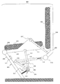
図1は、本発明の実施の形態1に係る椅子400の構成を示す側面模式図である。ここでは椅子400の構成を説明するために必要な部分のみを示した。以下では、始めに椅子400の全体的な構成を説明し、その後に椅子400のリンク機構の詳細について説明する。
FIG. 1 is a schematic side view showing the configuration of a
椅子400は、座面部301と背面部302を備える。
座面部301は、後述する第6リンク201上に固定されている。
背面部302は、後述する第8リンク204上に固定されている。
The
The
The
第6リンク201は、座面部301を下方から支持し、後述の第7リンク202と、後述する第5関節部203を介して接続されている。
また、第6リンク201は、座面部301に座るユーザの側面に相当する部分が上方に盛り上がっている。その盛り上がった部分は、後述する第9リンク206を介して、第8リンク204と接続されている。
The
In addition, the
第7リンク202は、椅子400の自重および座面部301に座るユーザの体重を支えるベース部の役割を果たす。第7リンク202とは別にベース部を設け、第7リンク202と接続してもよい。
第5関節部203は、例えばヒンジジョイントで構成され、第6リンク201と第7リンク202を回動可能に接続する。第5関節部203は、回転ばねなどの弾性力を付与する手段を有していない。座面部301に座るユーザの体重は、後述するリンク機構が椅子400に弾性を付与することによって支えられる。
The
The fifth
第8リンク204は、背面部302の後方に配置され、背面部302を介して座面部301に座るユーザの背中を後方から支持する。
第8リンク204は、後述する第9リンク206を介して、ユーザの側面に相当する位置で第6リンク201と接続されている。さらには、後述の第3リンク106と、後述の第6関節部112を介して接続されている。
The
The
第8リンク204には、第9リンク206が固定的に接続されている。
第9リンク206は、下記第7関節部207を介して第6リンク201と接続されている。
第7関節部207は、例えばヒンジジョイントで構成され、第6リンク201と第9リンク206を回動可能に接続する。
A
The
The seventh
第7関節部207は、上述の第6リンク201と第9リンク206の構成によって、第8リンク204および背面部302から前方に向かって所定距離離れた位置に配置されている。
この第7関節部207の位置は、ユーザが座面部301に着座したときに、ユーザの股関節の位置に概ね相当するようになっている。
The
The position of the
以上、椅子400の全体的な構成を説明した。
次に、椅子400のリンク機構について説明する。
The overall configuration of the
Next, the link mechanism of the
第6リンク201の底面は、第1リンク101で下方から支持されている。第1リンク101の一端と第6リンク201は、第4関節部111で接続されている。
第4関節部111は、例えばヒンジジョイントで構成され、第1リンク101の底面側と第6リンク201を回動可能に接続する。
The bottom surface of the
The 4th
第1リンク101の他端には、第1関節部103を介して第2リンク102が接続されている。
第2リンク102は、一端が第1関節部103と接続され、他端が後述の第2関節部104と接続されている。
A
The
上述の第7リンク202には、適当な接続機構を介して、第2関節部104が接続されている。
第2関節部104には、第2関節部104に回転方向の弾性力を付与する第1弾性抵抗手段105が設けられている。第1弾性抵抗手段105は、例えばねじりバネなどで構成することができる。
The second
The second
上述の第8リンク204には、後述の第6関節部112を介して、第3リンク106が回動可能に接続されている。
第3リンク106は、第6リンク201の下方に、第6リンク201と略平行に配置されており、一端は第6関節部112を介して第8リンク204と接続されている。また、下記第2弾性抵抗手段110が付与する反発弾性力によって第8リンクを図1の右方向(ユーザの背面方向)に押す役割を果たす。
第2弾性抵抗手段110は、例えば反発バネなどで構成され、第3リンク106に反発弾性力を付与して第8リンクを図1の右方向に押させる機能を有する。具体的な動作は、後述の図2で説明する。
第6関節部112は、例えばヒンジジョイントで構成され、第8リンク204と第3リンク106を回動可能に接続する。
The
The
The second elastic resistance means 110 is composed of, for example, a repulsive spring, and has a function of applying a repulsive elastic force to the
The sixth
第3リンク106の他端には、第3関節部108が設けられている。
第3関節部108と第2関節部104の間は、第4リンク107で接続されている。
第3関節部108と第1関節部103の間は、第5リンク109で接続されている。
A
A
A
以上、椅子400のリンク機構について説明した。
次に、椅子400の座面部301にユーザが着座するときの各部の動作を説明する。
The link mechanism of the
Next, the operation of each part when the user is seated on the
図2は、ユーザが座面部301に着座して背面部302にもたれかかるときの各部の変化を示す図である。ここでは、図1に示す各部のうち、説明に必要な部分のみを抜粋して記載した。
FIG. 2 is a diagram illustrating changes in each part when the user is seated on the
図2(a)は、ユーザが座面部301に着座する前の状態を示す。同図に示す状態は、図1に示す各部の状態と同様である。
FIG. 2A shows a state before the user is seated on the
図2(b)は、ユーザが座面部301に着座し、背面部302にもたれかかる前の状態を示す。以下、図2(a)から図2(b)に至る過程を説明する。
FIG. 2B shows a state before the user is seated on the
(1)ユーザが座面部301に着座すると、第6リンク201は、第5関節部203を支点として沈み込むように回転する。このとき、第6リンク201の底面側を支持する第1リンク101は、下方に向けて押圧される。
(2)第1リンク101は、第1関節部103を下方に押圧する。
(1) When the user is seated on the
(2) The
(3)第1関節部103が下方に向けて押圧されるにともなって、第2リンク102が第2関節部104を中心に下方へ向けて回転する。また、第2関節部104は、図2の正面から見て右回りに回転する。
(4)第2関節部104が右回りに回転すると、第1弾性抵抗手段105の弾性力がこれに反発して左回りに働き、第2リンク102や第1リンク101を上方へ押し上げる向きの弾性力が作用する。
(3) As the first
(4) When the second
(5)ユーザの体重とこの弾性力が釣り合った時点で第6リンク201の回転が止まり、座面部301の沈み込みが止まる。この時点で、ユーザの座り込み姿勢が定まる。
(6)一方、第1関節部103が下方に向けて押圧されるにともなって、第3関節部108、第4リンク107、第5リンク109は、第2関節部104を中心に図2の正面から見て右回りの方向に回転力を受ける。
(5) When the weight of the user and this elastic force are balanced, the rotation of the
(6) On the other hand, as the first
(7)第3リンク106は、第3関節部108等が第2関節部104を中心に右回りに回転するにともない、第6関節部112と第8リンク204を後方に向けて押圧する。
これにともなって、第8リンク204は第7関節部207を中心に、図2の左回りに回転する。また、第6リンク201と第8リンク204の間の角度が狭まる。
これにより、座面部301に着座したユーザにとっては、背面部302が背中に近づいてきて自動的にフィットするかのような効果が得られる。即ち、ユーザは座面部301に着座するのみで最適な着座姿勢が得られ、着座姿勢を調整するために背面部302を押す必要はない。
(7) The
Accordingly, the
Thereby, for the user seated on the
以上、ユーザが座面部301に着座する際の各部の動作を説明した。
The operation of each part when the user is seated on the
図2(c)は、ユーザが座面部301に着座した後、背面部302にもたれかかった際の状態を示す。以下、図2(b)から図2(c)に至る過程を説明する。
FIG. 2C shows a state in which the user leans against the
(8)ユーザが背面部302にもたれかかると、第8リンク204は、第7関節部207を回転中心とし、第9リンク206に支持されて、図2の正面から見て右回りに回転することになる。
(8) When the user leans against the
(9)第8リンク204が右回りに回転すると、第6関節部112が図2の正面から見て略左方向(ユーザの正面方向)に押圧されることになる。
(10)これにともなって、第2弾性抵抗手段110が押圧され、図2の右方向(ユーザの背面方向)に向けた反発弾性力が生じる。
(11)ユーザが背面部302にもたれかかる力とこの反発弾性力が釣り合った時点で、第8リンク204の傾きが止まり、ユーザの背もたれ姿勢が定まる。
(9) When the
(10) Along with this, the second elastic resistance means 110 is pressed, and a repulsive elastic force directed in the right direction (back direction of the user) in FIG. 2 is generated.
(11) When the force with which the user leans against the
(12)なお、図2(b)の状態において、ユーザが座面部301に着座した際に、背中が背面部302に接した状態で座り込む場合は、ユーザの背中が背面部302を押す力と第3リンク106が第8リンク204を押す力が対向し、第2弾性抵抗手段110を圧縮する。
これによって第2弾性抵抗手段110に生じた弾性力等が第8リンク204を後方に押す力と、ユーザの背中が背面部302を押す力とが釣り合った時点で、背面部302の位置、すなわちユーザの着座姿勢が定まる。
(12) In the state of FIG. 2B, when the user sits on the
As a result, the position of the
(13)また、第2弾性抵抗手段110の弾性係数を調整し、ユーザが背面部302にもたれかかった際に、第3リンク106を図2の左方向に押圧するよう構成することもできる。この場合、第1リンク101が第6リンク201を下方から押し上げる方向に回転力が働くことになり、背面部302と座面部301が連動して動作することになる。
(13) It is also possible to adjust the elastic coefficient of the second elastic resistance means 110 so that when the user leans against the
以上、椅子400の座面部301にユーザが着座するときの各部の動作を説明した。
なお、説明の容易の観点から、図1〜図2ではリンク機構を椅子400の側面から目視できるように記載したが、必要に応じて、リンク機構をケーシングなどで覆い、機構部分をユーザが視認できないようにしてもよい。
The operation of each part when the user is seated on the
In addition, from the viewpoint of easy explanation, in FIGS. 1 to 2, the link mechanism is described so as to be visible from the side surface of the
また、リンク機構は、椅子400から取り外すことができるようにモジュール化し、椅子用リンク機構として単体で設計、製造、修理、交換等ができるように構成することもできる。
この椅子用リンク機構には、第6リンク201、第7リンク202、その他の周辺部材を含めることもできる。いずれの周辺部品を椅子用リンク機構に含めるかは、椅子用リンク機構のモジュール化の程度等に合わせて、適宜定めればよい。
Also, the link mechanism can be modularized so that it can be removed from the
The link mechanism for the chair can also include a
以上のように、本実施の形態1に係る椅子400では、図2(b)〜図2(c)で説明したように、座面部301と背面部302は、ユーザが着座するにともなって連動して変化するようになっている。
したがって、ユーザは常に最適な着座姿勢をとることができる。
As described above, in the
Therefore, the user can always take the optimal sitting posture.
また、本実施の形態1に係る椅子400は、座面部301の下方に、図1〜図2で説明したリンク機構を備えている。
このリンク機構が備える第1弾性抵抗手段105や第2弾性抵抗手段110の弾性係数を調整することにより、座面部301を沈み込ませたり背面部302を傾けたりするときに必要な力の強さを調整することができる。
これにより、椅子400の座り心地や使用感を任意に調整することができる。
The
By adjusting the elastic coefficients of the first elastic resistance means 105 and the second elastic resistance means 110 provided in the link mechanism, the strength of force required when the
Thereby, the sitting comfort and usability of the
また、本実施の形態1に係る椅子400では、第8リンク204は第7関節部207を中心として回転する。
第7関節部207は、座面部301に着座するユーザの股関節に概ね相当する位置にあるため、第8リンク204および背面部302を、ユーザの股関節を中心として回転させることができる。
そのため、背面部302の回転動作を、人体構造に好適に適合させ、良好な着座感を提供することができる。
In the
Since the seventh
Therefore, the rotation operation of the
実施の形態2.
図3は、本発明の実施の形態2に係る椅子400の構成を示す側面模式図である。
本実施の形態2に係る椅子400は、第2関節部104に粘性抵抗を付与する第1粘性抵抗手段113、および第3リンク106に粘性抵抗を付与する第2粘性抵抗手段114を備える。
その他の構成は、実施の形態1の図1で説明したものと同様であるため、以下では差異点を中心に説明する。
FIG. 3 is a schematic side view showing the configuration of the
The
Other configurations are the same as those described with reference to FIG. 1 of the first embodiment, and therefore, the following description will focus on differences.
第1粘性抵抗手段113は、第1弾性抵抗手段105に回転力が加わったときに、これを緩衝する機能を有する。
第2粘性抵抗手段114は、第2弾性抵抗手段110に押圧力が加わったときに、これを緩衝する機能を有する。
第1粘性抵抗手段113と第2粘性抵抗手段114は、例えばオイル式のショックアブソーバで構成することができる。
The first viscous resistance means 113 has a function of buffering a rotational force applied to the first elastic resistance means 105.
The second viscous resistance means 114 has a function of buffering a pressing force applied to the second elastic resistance means 110.
The first viscous resistance means 113 and the second viscous resistance means 114 can be composed of, for example, an oil-type shock absorber.
第1粘性抵抗手段113と第2粘性抵抗手段114は、実施の形態1で説明した椅子用リンク機構の一部として構成することができる。 The first viscous resistance means 113 and the second viscous resistance means 114 can be configured as a part of the chair link mechanism described in the first embodiment.
本実施の形態2に係る椅子400は、第1粘性抵抗手段113を備えているので、ユーザが座面部301に着座したときの沈み込みを緩やかにすることができ、柔らかな座り込み感を提供することができる。
Since the
また、本実施の形態2に係る椅子400は、第2粘性抵抗手段114を備えているので、ユーザが背面部302にもたれかかったときの倒れ込みを緩やかにすることができ、柔らかな背もたれ感を提供することができる。
In addition, since the
実施の形態3.
実施の形態1〜2では、第1弾性抵抗手段105が第2関節部104に付与する弾性力を用いて、座面部301に上向きの反発力を付与し、座面部301がユーザの体重に対して抵抗するように構成した。
ただし、座面部301に極端に重い載置物を載せたりしたときなどは、第1弾性抵抗手段105の弾性力がこれに耐えられず、第2関節部104等が回転許容範囲を超えて回転し、破損してしまう可能性がある。
そこで、本発明の実施の形態3では、第6リンク201等が下方に沈み込む範囲を一定範囲内に制限する構成を説明する。
Embodiment 3 FIG.
In the first and second embodiments, an upward repulsive force is applied to the
However, when an extremely heavy object is placed on the
Therefore, in the third embodiment of the present invention, a configuration will be described in which the range in which the
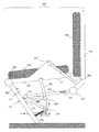
図4は、本実施の形態3に係る椅子400の構成を示す側面模式図である。
本実施の形態3に係る椅子400は、実施の形態1〜2で説明した構成に加えて、新たに補強板115、係止片116、第1ストッパ117を備える。その他の構成は、実施の形態1〜2と同様である。
なお、図4では、実施の形態1で説明した図1の構成に加えて、上述の各部を備えた例を図示した。以下では、図4を用いて上述の各部を説明する。
FIG. 4 is a schematic side view illustrating the configuration of the
The
In addition, in FIG. 4, in addition to the structure of FIG. 1 demonstrated in
補強板115は、第2リンク102、第4リンク107、および第5リンク109の間に形成されている三角形の空間を埋めて、これら3つのリンクの相対的な位置関係を一定に保つ。同時に、第1関節部103、第2関節部104、および第3関節部108の相対的位置関係は、補強板115によって常に同一に維持される。
これにより、ユーザが座面部301に着座して上記各リンクや各関節部が回転しても、第1関節部103、第2関節部104、および第3関節部108の相対的位置関係は、同一の三角形状に保たれる。
The reinforcing
Thereby, even if the user sits on the
係止片116は、第3関節部108から椅子400の前方に向かって突出した板状の部材で構成されている。後述の図5で、改めて詳細を説明する。
第1ストッパ117は、円柱状のゴム片で構成されており、第7リンク202の内側(図4の右側)、係止片116の上側に配置されている。
The
The
本実施の形態3における「相対位置固定機構」は、補強板115が相当する。
また、「第1回転制限手段」は、係止片116が相当する。
The “relative position fixing mechanism” in the third embodiment corresponds to the reinforcing
The “first rotation restricting means” corresponds to the
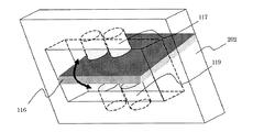
図5は、係止片116周辺の透過斜視図である。ここでは、係止片116周辺を椅子400の前面斜め下から見た図を示す。
係止片116は、第7リンク202よりも前方に突出した板状に構成されている。
第7リンク202の内側、係止片116の上側には、第1ストッパ117が配置されている。
FIG. 5 is a transparent perspective view around the
The
A
ユーザが座面部301に着座すると、補強板115および周辺部材が、図4の正面から見て右回りに回転する。係止片116は、この回転にともなって、同様に図4の正面から見て右回りに回転する。
ただし、係止片116の上下には、第1ストッパ117が配置されているため、係止片116が図5の上向きに回転可能な範囲は、第1ストッパ117が存在する位置までに限定される。
When the user sits on the
However, since the
一方、補強板115により、第1関節部103、第2関節部104、および第3関節部108の相対的位置関係は、同一の三角形状に保たれる。
そのため、係止片116が第1ストッパ117と接触して回転が止められた時点で、補強板115およびこれと接続されている周辺部材も、図5の上向きにそれ以上回転することができない。
したがって、第1リンク101や第6リンク201の沈み込みがこの時点で止まり、ユーザの座り込み位置が定まるのである。
On the other hand, the relative positions of the first
Therefore, when the
Therefore, the sinking of the
図6は、係止片116と第1ストッパ117が接触して補強板115および周辺部材の回転を止める様子を示す側面模式図である。
FIG. 6 is a schematic side view showing how the
図6(a)は、ユーザが座面部301に着座する前の状態を示す。同図に示す状態は、図4に示す各部の状態と同様である。
FIG. 6A shows a state before the user is seated on the
図6(b)は、ユーザが座面部301に着座し、背面部302にもたれかかる前の状態を示す。以下、各部の動作について説明する。
FIG. 6B shows a state before the user is seated on the
(1)ユーザが座面部301に着座すると、図2(b)で説明したように、第1関節部103、第2関節部104、第3関節部108等の各構成部材が図6の正面から見て右回りに回転する。このとき、各構成部材の相対的位置関係は、補強板115により一定の三角形状に維持されている。
(2)各構成部材が回転するにともなって、係止片116も右回りに回転する。
(1) When the user is seated on the
(2) As each constituent member rotates, the
(3)各構成部材および係止片116が一定程度回転すると、係止片116が第1ストッパ117と接触する。
(4)係止片116と第1ストッパの働きにより、各構成部材は右回りにそれ以上回転することができない。
(5)したがって、座面部301の沈み込みも、この時点で停止する。
(3) When each component member and the
(4) Due to the action of the
(5) Therefore, the sinking of the
以上、係止片116と第1ストッパ117の働きについて説明した。
なお、本実施の形態3では、補強板115の形状を三角形としたが、必ずしも三角形でなくともよく、接続する各部の相対的位置関係を一定に維持することができれば、任意の形状でよい。
また、本実施の形態3では、部材の保護等の観点から、第1ストッパ117を円柱状ゴムで構成したが、必ずしも円柱状ゴムでなくとも、係止片116の回転を止めることができる部材であれば、その他の部材を用いることもできる。
The function of the
In the third embodiment, the shape of the reinforcing
In the third embodiment, the
以上のように、本実施の形態3では、補強板115を用いて、第1関節部103、第2関節部104、および第3関節部108の相対的位置関係を一定に保つ。
そのため、ユーザが座面部301に着座したときに、第2リンク102と第4リンク107の間の角度が一定に保たれたままで第2リンク102が下方に押圧されることになるので、第1弾性抵抗手段105の弾性力が確実に作用する。
As described above, in the third embodiment, the relative positions of the first
Therefore, when the user is seated on the
また、本実施の形態3では、係止片116と第1ストッパ117を設け、第2関節部104が右回りに所定範囲まで回転した際に、係止片116と第1ストッパ117が接触して回転を制止するように構成されている。
そのため、例えば極端に重い載置物を座面部301に載せた場合でも、各部が許容範囲を超えて回転して破損等してしまうおそれがない。
In the third embodiment, the
Therefore, for example, even when an extremely heavy object is placed on the
実施の形態4.
本発明の実施の形態4では、座面部301の下方から上方に向けて一定の初期反発力をあらかじめ付与しておき、ユーザが座面部301に着座したときの着座感を調整する構成について説明する。
In the fourth embodiment of the present invention, a configuration will be described in which a predetermined initial repulsive force is applied in advance from the bottom to the top of the
図7は、本実施の形態4に係る椅子400の構成を示す側面模式図である。
本実施の形態4に係る椅子400は、実施の形態3で説明した構成に加えて、新たにプリテンショナ118、第2ストッパ119を備える。その他の構成は、実施の形態3と同様である。
なお図7では、記載の都合の観点から、一部の符号を省略したことを付言しておく。
FIG. 7 is a schematic side view showing the configuration of the
The
In FIG. 7, it is added that some symbols are omitted from the viewpoint of convenience of description.
プリテンショナ118は、第1リンク101を押し上げる方向(図7の上方)に、第2関節部104と第1弾性抵抗手段105を所定量回転させた状態で制止する手段である。
プリテンショナ118の一部は、第2関節部104の遠心方向に突出した突起物で形成されている。
プリテンショナ118の残りの部分は、この突起物を、第7リンク202の正面(図7の正面から見て左側)から奥(図7の正面から見て右側)へ向けて、押し込みネジ等の手段を用いて所定量押圧する。
プリテンショナ118の動作の詳細は、後述の図9で改めて説明する。
The
A part of the
The remaining portion of the
Details of the operation of the
第2ストッパ119は、円柱状のゴム片で構成され、第7リンク202の内側(図7の右側)、係止片116を下から支える位置に配置されている。
第2ストッパ119の働きの詳細は、後述の図9で改めて説明する。
The
Details of the function of the
本実施の形態4における「第2回転制限手段」は、第2ストッパ119が相当する。
The “second rotation limiting means” in the fourth embodiment corresponds to the
図8は、係止片116周辺の透過斜視図である。ここでは、係止片116周辺を椅子400の前面斜め下から見た図を示す。
実施の形態3で説明した図5と異なるのは、係止片116の下側に第2ストッパ119が配置されている点である。第2ストッパ119の働きにより、係止片116の下向きの回転は、所定範囲内に制限される。
FIG. 8 is a transparent perspective view around the
The difference from FIG. 5 described in the third embodiment is that a
図9は、係止片116と第2ストッパ119が接触して補強板115および周辺部材の回転を止める様子を示す側面模式図である。
FIG. 9 is a schematic side view showing how the
図9(a)は、ユーザが座面部301に着座する前の状態を示す。同図に示す状態は、図7に示す各部の状態と同様である。以下、各部の動作について説明する。
FIG. 9A shows a state before the user is seated on the
(1)プリテンショナ118の押し込みネジ部分を図9の右方向に向けて押し込むと、押し込みネジが第2関節部104から突出した突起部分を押圧し、第1リンク101を押し上げる方向に回転力が加わる。
(2)その結果、図9の矢印に示す方向に圧力が加わり、第1リンク101が下方から押し上げられる方向に力が作用する。そのため、ユーザが座面部301に着座する際に、下方から一定の力で抵抗力が作用することになるので、この抵抗力を調整することにより、着座感を調整することができる。
(1) When the pushing screw portion of the
(2) As a result, pressure is applied in the direction indicated by the arrow in FIG. 9, and a force acts in the direction in which the
(3)プリテンショナ118の作用によって、図9の矢印に示す方向に圧力が加わると、係止片116や周辺部材が下向き(図9の正面から見て左回り)に回転する。この回転を所定範囲内で制止するため、適当な位置に第2ストッパ119を配置しておき、係止片116と接触させる。
(4)係止片116と第2ストッパ119が接触した時点で、係止片116とその周辺部材の回転が止まる。この時点で、第6リンク201や座面部301等の位置が定まる。
(3) When pressure is applied in the direction indicated by the arrow in FIG. 9 by the action of the
(4) When the
(5)プリテンショナ118の押し込みネジ部分をさらに押し込むと、係止片116やその周辺部材はそれ以上回転しないが、第1弾性抵抗手段105はさらに押圧されることになる。そのため、第1弾性抵抗手段105の反発弾性力が高まり、ユーザが座面部301に着座した際に、第1リンク101や第6リンク201を介して座面部301を下方から押し上げる力が増す。
(6)即ち、プリテンショナ118の押し込みネジ部分の押し込み量を調整することによって、ユーザが座面部301に着座したときに下方から受ける抵抗力を調整し、着座感を調整することができるのである。
(5) When the pushing screw portion of the
(6) That is, by adjusting the push amount of the push screw portion of the
以上のように、本実施の形態4では、プリテンショナ118を用いて第1弾性抵抗手段105に初期弾性力を付与し、第1リンク101や第6リンク201を下方から押圧する力を作用させる。
これにより、ユーザが座面部301に着座したときに下方から抵抗力を与え、着座感を付与することができる。
As described above, in the fourth embodiment, an initial elastic force is applied to the first elastic resistance means 105 using the
Thereby, when the user is seated on the
また、本実施の形態4では、第2ストッパ119を用いて、係止片116とその周辺部材の下向きの回転を所定範囲内に制限する。
これにより、プリテンショナ118が第1弾性抵抗手段105に初期弾性力を付与して回転させても、第2ストッパ119の位置に応じて回転が止まるので、座面部301等の初期位置を任意に調整することができる。
In the fourth embodiment, the
As a result, even if the
また、本実施の形態4では、プリテンショナ118の押し込みネジの押し込み量を調整することにより、第1弾性抵抗手段105の初期弾性力を調整し、ユーザが座面部301に着座したときの抵抗力を調整することができる。
これにより、座面部301の着座感を任意に調整することができる。また、押し込みネジの押し込み量は、容易に調整することができるので、ユーザがこれを自ら調整して所望の着座感を得ることもできる。
In the fourth embodiment, the initial elastic force of the first elastic resistance means 105 is adjusted by adjusting the push amount of the push screw of the
Thereby, the seating feeling of the
実施の形態5.
本発明の実施の形態5では、実施の形態1〜4で説明した椅子400のリンク機構を簡易化した構成を説明する。実施の形態1〜4で説明したものと同様の部材については、同じ符号を付して説明を省略し、差異点を中心に説明する。
Embodiment 5 FIG.
In the fifth embodiment of the present invention, a configuration in which the link mechanism of the
図10は、本実施の形態5に係る椅子400の構成を示す側面模式図である。
本実施の形態5に係る椅子400は、座面部301、背面部302、第6リンク201、第7リンク202、第5関節部203、および第7関節部207については、実施の形態1〜4で説明したものと同様の構成を備える。
ただし、実施の形態1〜4と比較して、椅子400のリンク機構の構成が簡易化されている。また第2関節部104は第1弾性抵抗手段105を備えていない。以下では、リンク機構の構成を中心に説明する。
FIG. 10 is a schematic side view illustrating the configuration of the
In the
However, compared with Embodiment 1-4, the structure of the link mechanism of the
第7リンク202には、適当な接続機構を介して第2関節部104が接続されている。
The second
第5関節部203には、第5関節部203の回転方向に弾性力を付与する第3弾性抵抗手段208が設けられている。第3弾性抵抗手段208は、例えばねじりバネなどで構成することができる。
The fifth
第8リンク204、第6関節部112、および第3リンク106の接続関係は、実施の形態1〜4と同様である。
The connection relationship of the
本実施の形態5では、実施の形態1〜4と異なり、第1リンク101、第2リンク102、第1関節部103、第4リンク107、第3関節部108、第5リンク109、および第4関節部111は存在していない。これらの構成を省略することにより、椅子400の構成の簡易化を図っている。
In the fifth embodiment, unlike the first to fourth embodiments, the
以上、本実施の形態5に係る椅子400の構成について説明した。
次に、椅子400の座面部301にユーザが着座するときの各部の動作を説明する。
Heretofore, the configuration of the
Next, the operation of each part when the user is seated on the
図11は、ユーザが座面部301に着座して背面部302にもたれかかるときの各部の変化を示す図である。ここでは、図10に示す各部のうち、説明に必要な部分のみを抜粋して記載した。
FIG. 11 is a diagram illustrating changes in each part when the user is seated on the
図11(a)は、ユーザが座面部301に着座する前の状態を示す。同図に示す状態は、図10に示す各部の状態と同様である。
FIG. 11A shows a state before the user is seated on the
図11(b)は、ユーザが座面部301に着座し、背面部302にもたれかかる前の状態を示す。以下、図11(a)から図11(b)に至る過程を説明する。
FIG. 11B shows a state before the user is seated on the
(1)ユーザが座面部301に着座すると、第6リンク201は、第5関節部203を支点として沈み込むように回転する。
(2)第6リンク201が沈み込むにともなって、第8リンク204および第6関節部112も、第9リンク206に押圧されて下方に移動する。
(1) When the user is seated on the
(2) As the
(3)第6関節部112が下方に移動するにともなって、第3リンク106は、第2関節部104を支点として、図11の正面から見て右回りに回転する。また、第2関節部104も、これにともなって右回りに回転する。
(3) As the sixth
(4)また、第6リンク201が沈み込むにともなって、第6リンク201と第7リンク202の間の角度が小さくなり、第3弾性抵抗手段208によって、これに抵抗する方向の弾性力が生じる。
(5)ユーザの体重とこれらの弾性力が釣り合った時点で第6リンク201の回転が止まり、座面部301の沈み込みが止まる。
(4) Further, as the
(5) When the weight of the user and these elastic forces are balanced, the rotation of the
(6)この時点で、ユーザの座り込み姿勢が定まる。着座前と比較して、第6リンク201と第8リンク204の間の角度が狭まり、ユーザにとっては背面部302が自動的に背中に近づいてきてフィットするかのような効果を発揮する。即ち、実施の形態1〜4と同様に、ユーザが座面部301に着座するのみで最適な着座姿勢が得られるという効果が得られる。
(6) At this point, the user's sitting posture is determined. Compared to before sitting, the angle between the
以上、ユーザが座面部301に着座する際の各部の動作を説明した。
The operation of each part when the user is seated on the
図11(c)は、ユーザが座面部301に着座した後、背面部302にもたれかかった際の状態を示す。以下、図11(b)から図11(c)に至る過程を説明する。
FIG. 11C shows a state in which the user leans against the
(7)ユーザが背面部302にもたれかかると、第8リンク204は、第6関節部112を支点として背面へ向けて倒れ込む。
(8)同時に、第8リンク204は、第6関節部207を回転中心、第9リンク206を半径として、図11の正面から見て右回りに回転することになる。
(7) When the user leans against the
(8) At the same time, the
(9)第8リンク204が右回りに回転すると、第6関節部112が図11の正面から見て略左方向(ユーザの正面方向)に押圧されることになる。
(10)これにともなって、第2弾性抵抗手段110が押圧され、図11の右方向(ユーザの背面方向)に向けた反発弾性力が生じる。
(11)ユーザが背面部302にもたれかかる力とこの反発弾性力が釣り合った時点で、第8リンク204の傾きが止まり、ユーザの背もたれ姿勢が定まる。
(9) When the
(10) Along with this, the second elastic resistance means 110 is pressed, and a repulsive elastic force directed in the right direction (back direction of the user) in FIG. 11 is generated.
(11) When the force with which the user leans against the
以上、椅子400の座面部301にユーザが着座するときの各部の動作を説明した。
次に、実施の形態1〜4に係る椅子400と、本実施の形態5に係る椅子400とが同様の効果を発揮することについて、次の図12を用いて説明する。
The operation of each part when the user is seated on the
Next, it demonstrates using the following FIG. 12 that the
図12は、実施の形態1〜4に係る椅子400と、本実施の形態5に係る椅子400との差異を説明する図である。ここでは実施の形態1の図1を図12(a)で例示したが、実施の形態2〜4についても同様である。また、記載の都合上、各部の符号を省略した。
FIG. 12 is a diagram illustrating a difference between the
図12(a)では実施の形態1の図1で示した構造、図12(b)では本実施の形態5の図10で示した構造をそれぞれ比較のために示した。
図12(a)(b)に示すr2がともに等しい場合、図12(b)におけるr1を下記(式1)のように定める。
FIG. 12A shows the structure shown in FIG. 1 of the first embodiment, and FIG. 12B shows the structure shown in FIG. 10 of the fifth embodiment for comparison.
When r2 shown in FIGS. 12 (a) and 12 (b) are equal, r1 in FIG. 12 (b) is determined as in the following (formula 1).
r1=(r3/r4)r5 ・・・(式1) r1 = (r3 / r4) r5 (Formula 1)
上記(式1)のようにr1を定めれば、θ1の変位に対するθ2の変位が図12(a)と図12(b)でほぼ等しくなる。これにより、実施の形態1と同様に、ユーザが座面部301に着座するのみで、背面部302がユーザの背中に自動的にフィットするかのような効果を得ることができる。
If r1 is determined as in (Equation 1) above, the displacement of θ2 with respect to the displacement of θ1 is substantially equal in FIGS. 12 (a) and 12 (b). As a result, as in the first embodiment, it is possible to obtain an effect as if the
本実施の形態5では、第2関節部104は第1弾性抵抗手段105を備えておらず、これに代えて第5関節部203に第3弾性抵抗手段208を設けた例を説明したが、実施の形態1〜4と同様に、第2関節部104が第1弾性抵抗手段105を備えている構成を採用しても、本実施の形態5と同様の効果を発揮する。
さらには、第1弾性抵抗手段105と第3弾性抵抗手段208を併用してもよい。
以下の実施の形態6〜7においても同様である。
In the fifth embodiment, the second
Further, the first elastic resistance means 105 and the third elastic resistance means 208 may be used in combination.
The same applies to the following sixth to seventh embodiments.
また、実施の形態1〜4において、第2関節部104に第1弾性抵抗手段105を設けることに代えて、本実施の形態5と同様に、第5関節部203に第3弾性抵抗手段208を設けてもよい。
さらには、第1弾性抵抗手段105と第3弾性抵抗手段208を併用してもよい。
これらの構成を採用した場合でも、実施の形態1〜4と同様の効果を発揮することができる。
Further, in the first to fourth embodiments, instead of providing the first elastic resistance means 105 in the second
Further, the first elastic resistance means 105 and the third elastic resistance means 208 may be used in combination.
Even when these configurations are employed, the same effects as in the first to fourth embodiments can be exhibited.
以上のように、本実施の形態5では、椅子400に弾性力を付与するリンク機構の構成を簡易化し、部品コスト等の削減を図ることができる。
ただし、図12で説明した距離r1を十分に大きく取ることができる必要があるため、これらに制約があるか否かなどを考慮したうえで、実施の形態1〜4の構成と本実施の形態5の構成のいずれを採用するかを適宜定めるとよい。
As described above, in the fifth embodiment, it is possible to simplify the configuration of the link mechanism that imparts elastic force to the
However, since the distance r1 described in FIG. 12 needs to be sufficiently large, the configurations of the first to fourth embodiments and the present embodiment are considered in consideration of whether these are restricted. It may be determined as appropriate which of the five configurations is adopted.
実施の形態6.
図13は、本発明の実施の形態6に係る椅子400の構成を示す側面模式図である。
本実施の形態6に係る椅子400は、実施の形態5で説明した構成に加えて、実施の形態2で説明した第2粘性抵抗手段114を備える。その他の構成は、実施の形態5と同様である。
Embodiment 6 FIG.
FIG. 13 is a schematic side view showing the configuration of the
The
本実施の形態6に係る椅子400によれば、実施の形態5で説明した効果に加えて、実施の形態2で説明した効果を発揮することができる。
According to the
実施の形態7.
以上の実施の形態1〜6において、第7関節部207に回転方向の弾性力を付与する第4弾性抵抗手段を設けてもよい。これにより、第2弾性抵抗手段110と併せて、ユーザが背面部302にもたれかかるときの抵抗力を調整することができる。
Embodiment 7 FIG.
In the above first to sixth embodiments, fourth elastic resistance means for applying elastic force in the rotational direction to the seventh
また、第3弾性抵抗手段208に回転力が加わった際にこれを吸収する第3粘性抵抗手段を設けてもよい。
さらには、第4弾性抵抗手段に回転力が加わった際にこれを吸収する第4粘性抵抗手段を設けてもよい。
さらには、実施の形態5において、第2関節部104が第1弾性抵抗手段105を備えている構成を採用した場合、第2関節部104に粘性抵抗を付与する第1粘性抵抗手段113を設けてもよい。
Moreover, you may provide the 3rd viscous resistance means which absorbs this, when a rotational force is added to the 3rd elastic resistance means 208. FIG.
Furthermore, you may provide the 4th viscous resistance means which absorbs this, when rotational force is added to a 4th elastic resistance means.
Furthermore, in the fifth embodiment, when the configuration in which the second
なお、以上の実施の形態1〜7で用いた図面は、構成を説明するための模式図であり、実際の椅子400の各部サイズ等を正確に表したものではないことを付言しておく。
It should be noted that the drawings used in the first to seventh embodiments are schematic diagrams for explaining the configuration, and do not accurately represent the size of each part of the
101 第1リンク、102 第2リンク、103 第1関節部、104 第2関節部、105 第1弾性抵抗手段、106 第3リンク、107 第4リンク、108 第3関節部、109 第5リンク、110 第2弾性抵抗手段、111 第4関節部、112 第6関節部、113 第1粘性抵抗手段、114 第2粘性抵抗手段、115 補強板、116 係止片、117 第1ストッパ、118 プリテンショナ、119 第2ストッパ、201 第6リンク、202 第7リンク、203 第5関節部、204 第8リンク、206 第9リンク、207 第7関節部、208 第3弾性抵抗手段、301 座面部、302 背面部、400 椅子。
101 1st link, 102 2nd link, 103 1st joint part, 104 2nd joint part, 105 1st elastic resistance means, 106 3rd link, 107 4th link, 108 3rd joint part, 109 5th link, 110 2nd elastic resistance means, 111 4th joint part, 112 6th joint part, 113 1st viscosity resistance means, 114 2nd viscosity resistance means, 115 reinforcing plate, 116 locking piece, 117 1st stopper, 118
本発明に係る椅子は、座面部と、背面部と、前記座面部を支持する第6リンクと、前記背面部を支持する第8リンクと、前記第8リンクに一端が接続される第3リンクと、前記第6リンクの底面に一端が接続される第1リンクと、前記第1リンクの他端に一端が接続される第2リンクと、一端が前記第2リンクの他端に接続され、他端が前記第3リンクの他端に接続される第4リンクと、前記第2リンクの他端と直接的または間接的に接続される第7リンクと、一端が前記第1リンクの他端および前記第2リンクの一端に接続され、他端が前記第3リンクの他端および前記第4リンクの他端に接続される第5リンクと、前記第1リンクの他端、前記第2リンクの一端および前記第5リンクの一端の接続部に設けられ、これらリンクを回転可能に接続する第1関節部と、前記第7リンクに設けられ、前記第2リンクの他端および前記第4リンクの一端の接続部に設けられ、これらリンクを回転可能に接続する第2関節部と、前記第3リンクの他端、前記第4リンクの他端および前記第5リンクの他端の接続部に設けられ、これらリンクを回転可能に接続する第3関節部と、前記第6リンクの底面と前記第1リンクの一端の接続部に設けられ、これらリンクを回転可能に接続する第4関節部と、前記第6リンクと前記第7リンクの接続部に設けられ、これらリンクを回転可能に接続する第5関節部と、前記第3リンクの一端と前記第8リンクの接続部に設けられ、これらリンクを回転可能に接続する第6関節部と、前記第6リンクと前記第8リンクを直接的または間接的に接続し、前記第6リンクと前記第8リンクを回転可能に接続する第7関節部と、前記第2関節部において、前記座面部が押圧された際、該押圧力によって前記第2リンクが回転する方向とは反対の方向に弾性力を付与する第1弾性抵抗手段と、を備えるものである。 Chair child according to the present invention includes a seat surface portion, a rear portion, and a sixth link that supports the seat surface portion, and the eighth link that supports the back surface portion, a third of which one end is connected to the eighth link A link, a first link having one end connected to the bottom surface of the sixth link, a second link having one end connected to the other end of the first link, and one end connected to the other end of the second link. A fourth link whose other end is connected to the other end of the third link, a seventh link connected directly or indirectly to the other end of the second link, and one end other than the first link. A fifth link connected to an end and one end of the second link, and the other end connected to the other end of the third link and the other end of the fourth link; the other end of the first link; the second Provided at the connection part of one end of the link and one end of the fifth link, these links can be rotated A first joint part to be connected; and a second joint part provided at the seventh link, provided at a connection part at the other end of the second link and at one end of the fourth link, and rotatably connecting these links. The third link, the other end of the fourth link, and the other end of the fifth link. The third joint for rotatably connecting these links, and the sixth link Provided at the connecting portion between the bottom surface and one end of the first link, and provided at the connecting portion of the fourth link and the sixth link and the seventh link for rotatably connecting these links. A fifth joint that is connected to the first link, an end of the third link, and a joint of the eighth link, and a sixth joint that rotatably connects the links, the sixth link, and the eighth link. Connected directly or indirectly, In the seventh joint portion that rotatably connects the sixth link and the eighth link, and the second joint portion, when the seat surface portion is pressed, the direction opposite to the direction in which the second link rotates by the pressing force First elastic resistance means for applying an elastic force in the direction of.
本発明に係る椅子によれば、利用者が着座すると第1リンクが座面部に押圧されて第1弾性抵抗手段の弾性力が作用する。これにより、利用者は背もたれを押すことなく最適な着座姿勢を取ることができる。 According to chair element according to the present invention, the elastic force of the first elastic resistance unit first link when the user is seated is pressed to the seat surface portion acts. Thereby, the user can take an optimal seating posture without pushing the backrest.
本実施の形態3における「相対位置固定機構」は、補強板115が相当する。
また、「第1回転制限手段」は、係止片116および第1ストッパ117が相当する。
The “relative position fixing mechanism” in the third embodiment corresponds to the reinforcing
The “first rotation restricting means” corresponds to the
本発明に係る椅子は、座面部と、該座面部の後方に設けられる背面部と、前記座面部を支持する第6リンクと、前記背面部を支持する第8リンクと、前記第8リンクに一端が接続される第3リンクと、前記第6リンクの底面に一端が接続される第1リンクと、前記第1リンクの他端に一端が接続される第2リンクと、一端が前記第2リンクの他端に接続され、他端が前記第3リンクの他端に接続される第4リンクと、上端が前記第6リンクの前端と接続され、前記第2リンクの他端と直接的または間接的に接続される第7リンクと、一端が前記第1リンクの他端および前記第2リンクの一端に接続され、他端が前記第3リンクの他端および前記第4リンクの他端に接続される第5リンクと、一端が前記第6リンクに接続され、他端が前記第8リンクに接続される第9リンクと、前記第1リンクの他端、前記第2リンクの一端および前記第5リンクの一端の接続部に設けられ、これらリンクを回転可能に接続する第1関節部と、前記第2リンクの他端と前記第4リンクの一端の接続部に設けられ、これらリンクを回転可能に接続する第2関節部と、前記第3リンクの他端、前記第4リンクの他端および前記第5リンクの他端の接続部に設けられ、これらリンクを回転可能に接続する第3関節部と、前記第6リンクの底面と前記第1リンクの一端の接続部に設けられ、これらリンクを回転可能に接続する第4関節部と、前記第6リンクと前記第7リンクの接続部に設けられ、これらリンクを回転可能に接続する第5関節部と、前記第3リンクの一端と前記第8リンクの接続部に設けられ、これらリンクを回転可能に接続する第6関節部と、前記第6リンクと前記第9リンクの一端の接続部に設けられ、前記第6リンクと前記第9リンク及び前記第8リンクとを回転可能に接続する第7関節部と、前記第2関節部において、前記座面部が押圧された際、該押圧力によって前記第2リンクが回転する方向とは反対の方向に弾性力を付与する第1弾性抵抗手段と、を備え、前記第4関節部は、前記座面部が押圧された際に前記座面部の回転中心となる前記第5関節部よりも後方に配置され、前記第2リンク、前記第4リンク及び前記第5リンクによって互いに接続された前記第1関節部、前記第2関節部及び前記第3関節部は、前記第4関節部及び前記第5関節部よりも下方に配置され、かつ、前記第3関節部は、前記座面部の上面が押圧された際、前記第2関節部を中心に回転して後方へ移動し、前記第6関節部は、前記第3関節部よりも後方に配置され、前記第7関節部は、前記第8リンクよりも前方で前記第5関節部よりも後方に配置され、前記第9リンクと前記第8リンクとは、前記第6関節部よりも上方で接続されるものである。 The chair according to the present invention includes a seat surface portion, a back surface portion provided behind the seat surface portion, a sixth link that supports the seat surface portion, an eighth link that supports the back surface portion, and the eighth link. A third link to which one end is connected; a first link having one end connected to the bottom surface of the sixth link; a second link having one end connected to the other end of the first link; A fourth link connected to the other end of the link, the other end connected to the other end of the third link, and an upper end connected to the front end of the sixth link, directly with the other end of the second link or A seventh link indirectly connected, one end connected to the other end of the first link and one end of the second link, the other end connected to the other end of the third link and the other end of the fourth link a fifth link which is connected one end connected to the sixth link, the other end 8 A ninth link that is connected to tank, the first link of the other end, is provided to the connecting portion of one end of one end and the fifth link of the second link, a first joint portion which connects these links rotatably If, before SL provided in the connection portion of the one end of the other end and the fourth link of the second link, and a second joint portion which connects these links rotatably, the other end of said third link, said fourth link Provided at a connection portion between the other end of the first link and the other end of the fifth link, and provided at a connection portion between the third joint for rotatably connecting the links, the bottom surface of the sixth link, and one end of the first link. A fourth joint for rotatably connecting these links, a fifth joint for rotatably connecting these links, and a third link provided at the connection between the sixth link and the seventh link. At one end of the second link and the connection portion of the eighth link A sixth joint portion that connects these links rotatably, the sixth link and is provided in the connecting portion of one end of the ninth link, rotatable and said sixth link ninth link and the eighth link In the seventh joint part connected to the first joint part and the second joint part, when the seat surface part is pressed, the first force is applied in the direction opposite to the direction in which the second link rotates by the pressing force. An elastic resistance means, and the fourth joint portion is disposed rearward of the fifth joint portion, which is the center of rotation of the seat surface portion when the seat surface portion is pressed, and the second link, The first joint part, the second joint part, and the third joint part connected to each other by the fourth link and the fifth link are disposed below the fourth joint part and the fifth joint part, And the upper surface of the said seat surface part is the said 3rd joint part. When pressed, it rotates about the second joint and moves rearwardly, the sixth joint is disposed behind the third joint, and the seventh joint is the eighth The ninth link and the eighth link are arranged in front of the link and behind the fifth joint, and the ninth link and the eighth link are connected to each other above the sixth joint .
Claims (23)
前記椅子の座面部を支持するリンクの底面に一端が接続される第1リンクと、
前記第1リンクの他端に一端が接続される第2リンクと、
前記第1リンクと前記第2リンクを回転可能に接続する第1関節部と、
前記第2リンクの他端に設けられた第2関節部と、
前記第2関節部に回転方向の弾性を付与する第1弾性抵抗手段と、
を備えたことを特徴とする椅子用リンク機構。 A link mechanism used for a chair,
A first link having one end connected to the bottom surface of the link supporting the seat surface portion of the chair;
A second link having one end connected to the other end of the first link;
A first joint that rotatably connects the first link and the second link;
A second joint provided at the other end of the second link;
First elastic resistance means for imparting rotational elasticity to the second joint portion;
A link mechanism for a chair, comprising:
一端が前記第3リンクの他端に接続され、他端が前記第2関節部に接続される第4リンクと、
前記第3リンクと前記第4リンクを回転可能に接続する第3関節部と、
前記第1関節部と前記第3関節部を接続する第5リンクと、
前記第3リンクに反発弾性を付与する第2弾性抵抗手段と、
を備えたことを特徴とする請求項1記載の椅子用リンク機構。 A third link having one end connected to the link supporting the back surface of the chair;
A fourth link having one end connected to the other end of the third link and the other end connected to the second joint;
A third joint that rotatably connects the third link and the fourth link;
A fifth link connecting the first joint and the third joint;
Second elastic resistance means for imparting rebound resilience to the third link;
The link mechanism for a chair according to claim 1, further comprising:
ことを特徴とする請求項2記載の椅子用リンク機構。 The link mechanism for a chair according to claim 2, further comprising first viscous resistance means for imparting viscous resistance to the second joint portion.
ことを特徴とする請求項2または請求項3記載の椅子用リンク機構。 The link mechanism for a chair according to claim 2 or 3, further comprising second viscous resistance means for imparting viscous resistance to the third link.
ことを特徴とする請求項2ないし請求項4のいずれかに記載の椅子用リンク機構。 5. The chair according to claim 2, further comprising first rotation limiting means for limiting rotation in a direction in which the second joint portion pulls the first link within a predetermined range. Link mechanism.
前記第1回転制限手段は、
前記相対位置固定機構の回転と連動して回転する係止片で構成されている
ことを特徴とする請求項5記載の椅子用リンク機構。 A relative position fixing mechanism that maintains a relative positional relationship between the first joint part, the second joint part, and the third joint part;
The first rotation limiting means includes
The link mechanism for a chair according to claim 5, comprising a locking piece that rotates in conjunction with rotation of the relative position fixing mechanism.
前記第1リンクと前記第6リンクを回転可能に接続する第4関節部と、
前記第2関節部と接続される第7リンクと、
前記第6リンクと前記第7リンクを回転可能に接続する第5関節部と、
を備えたことを特徴とする請求項2ないし請求項6のいずれかに記載の椅子用リンク機構。 A sixth link supporting the seat surface of the chair and connected to the first link at the bottom;
A fourth joint that rotatably connects the first link and the sixth link;
A seventh link connected to the second joint,
A fifth joint that rotatably connects the sixth link and the seventh link;
The link mechanism for a chair according to any one of claims 2 to 6, further comprising:
前記第1リンクと前記第6リンクを回転可能に接続する第4関節部と、
前記第2関節部と接続される第7リンクと、
前記第6リンクと前記第7リンクを回転可能に接続する第5関節部と、
を備え、
前記第7リンクは、
前記第2関節部が前記第1リンクを引っ張る方向に前記相対位置固定機構が回転する範囲を制限する第1ストッパを備えており、
前記第1ストッパは、
前記第2関節部が前記第1リンクを引っ張る方向に前記相対位置固定機構が所定位置まで回転した際に前記係止片と対向して接触する位置に配置されている
ことを特徴とする請求項6記載の椅子用リンク機構。 A sixth link supporting the seat surface of the chair and connected to the first link at the bottom;
A fourth joint that rotatably connects the first link and the sixth link;
A seventh link connected to the second joint,
A fifth joint that rotatably connects the sixth link and the seventh link;
With
The seventh link is
A first stopper for limiting a range in which the relative position fixing mechanism rotates in a direction in which the second joint portion pulls the first link;
The first stopper is
The said 2nd joint part is arrange | positioned in the position which faces the said locking piece and contacts when the said relative position fixing mechanism rotates to the predetermined position in the direction which pulls the said 1st link. 6. The link mechanism for chairs according to 6.
前記第5関節部に回転方向の弾性を付与する第3弾性抵抗手段を備えた
ことを特徴とする請求項7または請求項8記載の椅子用リンク機構。 Instead of the first elastic resistance means or in addition to the first elastic resistance means,
The link mechanism for a chair according to claim 7 or 8, further comprising third elastic resistance means for imparting rotational elasticity to the fifth joint portion.
ことを特徴とする請求項1ないし請求項8のいずれかに記載の椅子用リンク機構。 The link mechanism for a chair according to any one of claims 1 to 8, further comprising means for applying pretension to the first elastic resistance means.
前記第1リンクを押す方向に前記相対位置固定機構が回転する範囲を所定範囲内に制限する第2回転制限手段と、
を備えたことを特徴とする請求項6または請求項8記載の椅子用リンク機構。 Means for applying pretension to the first elastic resistance means;
A second rotation limiting means for limiting a range in which the relative position fixing mechanism rotates in a direction in which the first link is pushed to a predetermined range;
The link mechanism for a chair according to claim 6 or 8, further comprising:
前記第7リンクは、
前記第1リンクを押す方向に前記相対位置固定機構が回転する範囲を制限する第2ストッパを備えており、
前記第2ストッパは、
前記第1リンクを押す方向に前記相対位置固定機構が所定位置まで回転した際に前記係止片と対向して接触する位置に配置されている
ことを特徴とする請求項6または請求項8記載の椅子用リンク機構。 Means for applying pretension to the first elastic resistance means;
The seventh link is
A second stopper for limiting a range in which the relative position fixing mechanism rotates in a direction of pushing the first link;
The second stopper is
9. The device according to claim 6, wherein when the relative position fixing mechanism is rotated to a predetermined position in a direction in which the first link is pushed, the mechanism is disposed at a position where it comes into contact with the locking piece. Link mechanism for chairs.
請求項1ないし請求項12のいずれかに記載の椅子用リンク機構と、
前記背面部を支持し前記第3リンクおよび前記第6リンクと接続される第8リンクと、
前記第3リンクと前記第8リンクを回転可能に接続する第6関節部と、
前記第6リンクと前記第8リンクを回転可能に接続する第7関節部と、
を備え、
前記椅子用リンク機構を前記座面部の下方に配置し、
前記座面部を支持するリンクの底面に前記第1リンクを接続した
ことを特徴とする椅子。 A seat part, a back part,
A link mechanism for a chair according to any one of claims 1 to 12,
An eighth link supporting the back surface and connected to the third link and the sixth link;
A sixth joint that rotatably connects the third link and the eighth link;
A seventh joint that rotatably connects the sixth link and the eighth link;
With
The chair link mechanism is disposed below the seat surface portion,
The chair, wherein the first link is connected to the bottom surface of the link that supports the seat surface portion.
請求項1ないし請求項12のいずれかに記載の椅子用リンク機構と、
前記背面部を支持し前記第3リンクおよび前記第6リンクと接続される第8リンクと、
前記第3リンクと前記第8リンクを回転可能に接続する第6関節部と、
一端が前記第6リンクに接続され他端が前記第8リンクに接続される第9リンクと、
前記第6リンクと前記第9リンクを回転可能に接続する第7関節部と、
を備え、
前記第6リンクおよび前記第9リンクは、
前記第8リンクから前方に所定距離離した位置に前記第7関節部を配置するよう構成されており、
前記椅子用リンク機構を前記座面部の下方に配置し、
前記座面部を支持するリンクの底面に前記第1リンクを接続した
ことを特徴とする椅子。 A seat part, a back part,
A link mechanism for a chair according to any one of claims 1 to 12,
An eighth link supporting the back surface and connected to the third link and the sixth link;
A sixth joint that rotatably connects the third link and the eighth link;
A ninth link having one end connected to the sixth link and the other end connected to the eighth link;
A seventh joint that rotatably connects the sixth link and the ninth link;
With
The sixth link and the ninth link are:
The seventh joint is configured to be disposed at a position a predetermined distance away from the eighth link.
The chair link mechanism is disposed below the seat surface portion,
The chair, wherein the first link is connected to the bottom surface of the link that supports the seat surface portion.
前記座面部を支持する第6リンクと、
前記背面部を支持する第8リンクと、
前記第8リンクに一端が接続される第3リンクと、
前記第3リンクの他端と接続される第7リンクと、
前記第3リンクと前記第7リンクを回転可能に接続する第2関節部と、
前記第6リンクと前記第7リンクを回転可能に接続する第5関節部と、
前記第3リンクと前記第8リンクを回転可能に接続する第6関節部と、
前記第3リンクに反発弾性を付与する第2弾性抵抗手段と、
前記第5関節部に回転方向の弾性を付与する第3弾性抵抗手段と、
を備えたことを特徴とする椅子。 A seat part, a back part,
A sixth link for supporting the seat surface portion;
An eighth link supporting the back surface;
A third link having one end connected to the eighth link;
A seventh link connected to the other end of the third link;
A second joint that rotatably connects the third link and the seventh link;
A fifth joint that rotatably connects the sixth link and the seventh link;
A sixth joint that rotatably connects the third link and the eighth link;
Second elastic resistance means for imparting rebound resilience to the third link;
Third elastic resistance means for imparting rotational elasticity to the fifth joint portion;
A chair characterized by comprising
ことを特徴とする請求項15記載の椅子。 The chair according to claim 15, further comprising a seventh joint that rotatably connects the sixth link and the eighth link.
前記第6リンクと前記第9リンクを回転可能に接続する第7関節部と、
を備え、
前記第6リンクおよび前記第9リンクは、
前記第8リンクから前方に所定距離離した位置に前記第7関節部を配置するよう構成されている
ことを特徴とする請求項15記載の椅子。 A ninth link having one end connected to the sixth link and the other end connected to the eighth link;
A seventh joint that rotatably connects the sixth link and the ninth link;
With
The sixth link and the ninth link are:
The chair according to claim 15, wherein the seventh joint portion is arranged at a position spaced a predetermined distance forward from the eighth link.
前記第2関節部に回転方向の弾性を付与する第1弾性抵抗手段を備えた
ことを特徴とする請求項15ないし請求項17のいずれかに記載の椅子。 Instead of the third elastic resistance means or in addition to the third elastic resistance means,
The chair according to any one of claims 15 to 17, further comprising first elastic resistance means for imparting elasticity in a rotational direction to the second joint portion.
ことを特徴とする請求項18記載の椅子。 The chair according to claim 18, further comprising first viscous resistance means for imparting viscous resistance to the second joint portion.
ことを特徴とする請求項15ないし請求項17のいずれかに記載の椅子。 The chair according to any one of claims 15 to 17, further comprising third viscous resistance means for imparting viscous resistance to the fifth joint portion.
ことを特徴とする請求項15ないし請求項20のいずれかに記載の椅子。 The chair according to any one of claims 15 to 20, further comprising second viscous resistance means for imparting viscous resistance to the third link.
ことを特徴とする請求項13、14、16、または17記載の椅子。 The chair according to claim 13, 14, 16, or 17, further comprising a fourth elastic resistance unit that imparts rotational elasticity to the seventh joint portion.
ことを特徴とする請求項22記載の椅子。 The chair according to claim 22, further comprising fourth viscous resistance means for imparting viscous resistance to the seventh joint portion.
Priority Applications (8)
| Application Number | Priority Date | Filing Date | Title |
|---|---|---|---|
| JP2008260244A JP4379538B1 (en) | 2008-10-07 | 2008-10-07 | Link mechanism for chair, chair |
| US12/289,984 US7971936B2 (en) | 2008-10-07 | 2008-11-07 | Link mechanism for a chair and a chair |
| PCT/JP2009/064467 WO2010041518A1 (en) | 2008-10-07 | 2009-08-18 | Link mechanism for chair, and chair |
| EP09819054.9A EP2316304B1 (en) | 2008-10-07 | 2009-08-18 | Link mechanism for chair, and chair |
| CA2734854A CA2734854C (en) | 2008-10-07 | 2009-08-18 | Link mechanism for a chair and a chair |
| KR1020117003766A KR101488558B1 (en) | 2008-10-07 | 2009-08-18 | Link mechanism for chair, and chair |
| CN2009801322211A CN102123634B (en) | 2008-10-07 | 2009-08-18 | Link mechanism for chair, and chair |
| US12/923,642 US8029061B2 (en) | 2008-10-07 | 2010-09-30 | Link mechanism for a chair and a chair |
Applications Claiming Priority (1)
| Application Number | Priority Date | Filing Date | Title |
|---|---|---|---|
| JP2008260244A JP4379538B1 (en) | 2008-10-07 | 2008-10-07 | Link mechanism for chair, chair |
Publications (2)
| Publication Number | Publication Date |
|---|---|
| JP4379538B1 JP4379538B1 (en) | 2009-12-09 |
| JP2010088589A true JP2010088589A (en) | 2010-04-22 |
Family
ID=41459739
Family Applications (1)
| Application Number | Title | Priority Date | Filing Date |
|---|---|---|---|
| JP2008260244A Active JP4379538B1 (en) | 2008-10-07 | 2008-10-07 | Link mechanism for chair, chair |
Country Status (7)
| Country | Link |
|---|---|
| US (2) | US7971936B2 (en) |
| EP (1) | EP2316304B1 (en) |
| JP (1) | JP4379538B1 (en) |
| KR (1) | KR101488558B1 (en) |
| CN (1) | CN102123634B (en) |
| CA (1) | CA2734854C (en) |
| WO (1) | WO2010041518A1 (en) |
Families Citing this family (15)
| Publication number | Priority date | Publication date | Assignee | Title |
|---|---|---|---|---|
| US8251448B2 (en) * | 2007-03-13 | 2012-08-28 | Hni Technologies Inc. | Dynamic chair back lumbar support system |
| GB2492706B (en) | 2010-05-05 | 2016-06-22 | Allsteel Inc | Moveable and demountable wall panel system for butt-glazed wall panels |
| CN102946762B (en) | 2010-06-11 | 2015-12-16 | 株式会社冈村制作所 | Chair |
| CN105361489B (en) * | 2011-03-30 | 2019-03-29 | 美国皮革制品经营有限责任公司 | Seat |
| US9301895B2 (en) | 2013-03-15 | 2016-04-05 | Stryker Corporation | Medical support apparatus |
| US9332851B2 (en) | 2013-03-15 | 2016-05-10 | Hni Technologies Inc. | Chair with activated back flex |
| US9801471B2 (en) | 2014-04-17 | 2017-10-31 | Hni Technologies Inc. | Chair and chair control assemblies, systems, and methods |
| USD731833S1 (en) | 2014-04-17 | 2015-06-16 | Allsteel Inc. | Chair |
| WO2015160693A1 (en) | 2014-04-17 | 2015-10-22 | Hni Technologies Inc. | Flex lumbar support |
| EP2946694B1 (en) * | 2014-05-22 | 2016-11-30 | Pro-Cord S.p.A. | A chair with a tilting backrest |
| GB201412733D0 (en) | 2014-07-17 | 2014-09-03 | Boss Design Ltd | Chair |
| US9718382B2 (en) * | 2014-10-02 | 2017-08-01 | Bose Corporation | Seat suspension |
| US9801470B2 (en) | 2014-10-15 | 2017-10-31 | Hni Technologies Inc. | Molded chair with integrated support and method of making same |
| USD743180S1 (en) | 2014-10-15 | 2015-11-17 | Hni Technologies Inc. | Chair |
| US10729246B2 (en) | 2017-12-21 | 2020-08-04 | Stryker Corporation | Person support apparatus with shear-reducing pivot assembly |
Family Cites Families (12)
| Publication number | Priority date | Publication date | Assignee | Title |
|---|---|---|---|---|
| CH645795A5 (en) * | 1979-07-23 | 1984-10-31 | Drabert Soehne | Chair, in particular visual display unit chair |
| US4627663A (en) * | 1984-04-04 | 1986-12-09 | La-Z-Boy Chair Company | Reclining chair |
| JPS61176990A (en) | 1985-01-31 | 1986-08-08 | ヤマハ株式会社 | Automatic performer |
| DE3617624A1 (en) * | 1986-05-26 | 1987-12-03 | Drabert Soehne | CHAIR |
| DE3632131C2 (en) * | 1986-06-04 | 2001-12-13 | Hartmut S Engel | Functional seating |
| JPS6416488A (en) | 1987-07-10 | 1989-01-19 | Ichiro Sato | Rotational drive |
| JPH0798244B2 (en) | 1990-05-31 | 1995-10-25 | 株式会社アーレスティ | Masking device for disintegrating Okiko |
| DE4019876A1 (en) * | 1990-06-22 | 1992-01-02 | Simon Desanta | CHAIR, ESPECIALLY OFFICE CHAIR |
| ATE209011T1 (en) | 1996-10-14 | 2001-12-15 | Vitra Patente Ag | FRAME CONSTRUCTION, ADJUSTING MECHANICS AND UPHOLSTERY COVER FOR A CHAIR |
| JP2001029169A (en) | 1999-07-23 | 2001-02-06 | Takano Co Ltd | Chair supporting device |
| JP4037438B2 (en) * | 2006-06-29 | 2008-01-23 | 沖電気工業株式会社 | Chair |
| JP4697892B2 (en) | 2007-02-16 | 2011-06-08 | 株式会社イトーキ | Chair |
-
2008
- 2008-10-07 JP JP2008260244A patent/JP4379538B1/en active Active
- 2008-11-07 US US12/289,984 patent/US7971936B2/en not_active Expired - Fee Related
-
2009
- 2009-08-18 CN CN2009801322211A patent/CN102123634B/en not_active Expired - Fee Related
- 2009-08-18 KR KR1020117003766A patent/KR101488558B1/en active IP Right Grant
- 2009-08-18 EP EP09819054.9A patent/EP2316304B1/en not_active Not-in-force
- 2009-08-18 CA CA2734854A patent/CA2734854C/en not_active Expired - Fee Related
- 2009-08-18 WO PCT/JP2009/064467 patent/WO2010041518A1/en active Application Filing
-
2010
- 2010-09-30 US US12/923,642 patent/US8029061B2/en not_active Expired - Fee Related
Also Published As
| Publication number | Publication date |
|---|---|
| US20100084902A1 (en) | 2010-04-08 |
| US7971936B2 (en) | 2011-07-05 |
| US8029061B2 (en) | 2011-10-04 |
| KR101488558B1 (en) | 2015-02-02 |
| EP2316304A4 (en) | 2014-03-26 |
| EP2316304A1 (en) | 2011-05-04 |
| CN102123634B (en) | 2013-05-29 |
| WO2010041518A1 (en) | 2010-04-15 |
| JP4379538B1 (en) | 2009-12-09 |
| US20110031794A1 (en) | 2011-02-10 |
| KR20110086795A (en) | 2011-08-01 |
| CA2734854A1 (en) | 2010-04-15 |
| CA2734854C (en) | 2014-05-27 |
| CN102123634A (en) | 2011-07-13 |
| EP2316304B1 (en) | 2015-10-21 |
Similar Documents
| Publication | Publication Date | Title |
|---|---|---|
| JP4379538B1 (en) | Link mechanism for chair, chair | |
| WO2010109728A1 (en) | Chair | |
| KR20050036999A (en) | Seating unit having motion control | |
| JP5509200B2 (en) | Chair with control system | |
| JP4996240B2 (en) | Chair | |
| CN111200955A (en) | Chair with self-adjusting joint | |
| JP4729687B2 (en) | Chair with tilting mechanism of seat | |
| JP5460997B2 (en) | Hinge structure and chair back support structure using it | |
| JP2013000446A (en) | Chair | |
| WO2010050174A1 (en) | Chair | |
| JP2010094278A (en) | Chair | |
| JP5279773B2 (en) | Chair back support mechanism | |
| JP2013000445A (en) | Chair | |
| WO2006107214A1 (en) | Chair comprising a plate body attached to a base where a part of said plate body is designed as a torsion body. | |
| JP6777281B2 (en) | Chair | |
| JP5378760B2 (en) | Chair | |
| JP5452904B2 (en) | Chair | |
| JP6860320B2 (en) | Chair | |
| JP5576186B2 (en) | Chair | |
| JP5566438B2 (en) | Chair back support mechanism | |
| JP2022070286A (en) | Chair | |
| JP2011255075A (en) | Chair | |
| JP2010094277A5 (en) | ||
| JP2008080091A (en) | Chair | |
| IES81161B2 (en) | A chair |
Legal Events
| Date | Code | Title | Description |
|---|---|---|---|
| TRDD | Decision of grant or rejection written | ||
| A01 | Written decision to grant a patent or to grant a registration (utility model) |
Free format text: JAPANESE INTERMEDIATE CODE: A01 Effective date: 20090825 |
|
| A01 | Written decision to grant a patent or to grant a registration (utility model) |
Free format text: JAPANESE INTERMEDIATE CODE: A01 |
|
| A61 | First payment of annual fees (during grant procedure) |
Free format text: JAPANESE INTERMEDIATE CODE: A61 Effective date: 20090907 |
|
| FPAY | Renewal fee payment (event date is renewal date of database) |
Free format text: PAYMENT UNTIL: 20121002 Year of fee payment: 3 |
|
| R150 | Certificate of patent or registration of utility model |
Ref document number: 4379538 Country of ref document: JP Free format text: JAPANESE INTERMEDIATE CODE: R150 Free format text: JAPANESE INTERMEDIATE CODE: R150 |
|
| FPAY | Renewal fee payment (event date is renewal date of database) |
Free format text: PAYMENT UNTIL: 20121002 Year of fee payment: 3 |
|
| S531 | Written request for registration of change of domicile |
Free format text: JAPANESE INTERMEDIATE CODE: R313531 |
|
| FPAY | Renewal fee payment (event date is renewal date of database) |
Free format text: PAYMENT UNTIL: 20121002 Year of fee payment: 3 |
|
| R350 | Written notification of registration of transfer |
Free format text: JAPANESE INTERMEDIATE CODE: R350 |
|
| FPAY | Renewal fee payment (event date is renewal date of database) |
Free format text: PAYMENT UNTIL: 20121002 Year of fee payment: 3 |
|
| FPAY | Renewal fee payment (event date is renewal date of database) |
Free format text: PAYMENT UNTIL: 20131002 Year of fee payment: 4 |