EP2316304A1 - Link mechanism for chair, and chair - Google Patents
Link mechanism for chair, and chair Download PDFInfo
- Publication number
- EP2316304A1 EP2316304A1 EP09819054A EP09819054A EP2316304A1 EP 2316304 A1 EP2316304 A1 EP 2316304A1 EP 09819054 A EP09819054 A EP 09819054A EP 09819054 A EP09819054 A EP 09819054A EP 2316304 A1 EP2316304 A1 EP 2316304A1
- Authority
- EP
- European Patent Office
- Prior art keywords
- link
- joint portion
- chair
- surface portion
- whose
- Prior art date
- Legal status (The legal status is an assumption and is not a legal conclusion. Google has not performed a legal analysis and makes no representation as to the accuracy of the status listed.)
- Granted
Links
Images


Classifications
-
- A—HUMAN NECESSITIES
- A47—FURNITURE; DOMESTIC ARTICLES OR APPLIANCES; COFFEE MILLS; SPICE MILLS; SUCTION CLEANERS IN GENERAL
- A47C—CHAIRS; SOFAS; BEDS
- A47C1/00—Chairs adapted for special purposes
- A47C1/02—Reclining or easy chairs
- A47C1/031—Reclining or easy chairs having coupled concurrently adjustable supporting parts
- A47C1/032—Reclining or easy chairs having coupled concurrently adjustable supporting parts the parts being movably-coupled seat and back-rest
- A47C1/03261—Reclining or easy chairs having coupled concurrently adjustable supporting parts the parts being movably-coupled seat and back-rest characterised by elastic means
-
- A—HUMAN NECESSITIES
- A47—FURNITURE; DOMESTIC ARTICLES OR APPLIANCES; COFFEE MILLS; SPICE MILLS; SUCTION CLEANERS IN GENERAL
- A47C—CHAIRS; SOFAS; BEDS
- A47C1/00—Chairs adapted for special purposes
- A47C1/02—Reclining or easy chairs
- A47C1/022—Reclining or easy chairs having independently-adjustable supporting parts
-
- A—HUMAN NECESSITIES
- A47—FURNITURE; DOMESTIC ARTICLES OR APPLIANCES; COFFEE MILLS; SPICE MILLS; SUCTION CLEANERS IN GENERAL
- A47C—CHAIRS; SOFAS; BEDS
- A47C1/00—Chairs adapted for special purposes
- A47C1/02—Reclining or easy chairs
- A47C1/031—Reclining or easy chairs having coupled concurrently adjustable supporting parts
- A47C1/032—Reclining or easy chairs having coupled concurrently adjustable supporting parts the parts being movably-coupled seat and back-rest
- A47C1/03205—Reclining or easy chairs having coupled concurrently adjustable supporting parts the parts being movably-coupled seat and back-rest having adjustable and lockable inclination
- A47C1/03238—Reclining or easy chairs having coupled concurrently adjustable supporting parts the parts being movably-coupled seat and back-rest having adjustable and lockable inclination by means of peg-and-notch or pawl-and-ratchet mechanism
-
- A—HUMAN NECESSITIES
- A47—FURNITURE; DOMESTIC ARTICLES OR APPLIANCES; COFFEE MILLS; SPICE MILLS; SUCTION CLEANERS IN GENERAL
- A47C—CHAIRS; SOFAS; BEDS
- A47C1/00—Chairs adapted for special purposes
- A47C1/02—Reclining or easy chairs
- A47C1/031—Reclining or easy chairs having coupled concurrently adjustable supporting parts
- A47C1/032—Reclining or easy chairs having coupled concurrently adjustable supporting parts the parts being movably-coupled seat and back-rest
- A47C1/03261—Reclining or easy chairs having coupled concurrently adjustable supporting parts the parts being movably-coupled seat and back-rest characterised by elastic means
- A47C1/03272—Reclining or easy chairs having coupled concurrently adjustable supporting parts the parts being movably-coupled seat and back-rest characterised by elastic means with coil springs
- A47C1/03274—Reclining or easy chairs having coupled concurrently adjustable supporting parts the parts being movably-coupled seat and back-rest characterised by elastic means with coil springs of torsion type
-
- A—HUMAN NECESSITIES
- A47—FURNITURE; DOMESTIC ARTICLES OR APPLIANCES; COFFEE MILLS; SPICE MILLS; SUCTION CLEANERS IN GENERAL
- A47C—CHAIRS; SOFAS; BEDS
- A47C7/00—Parts, details, or accessories of chairs or stools
- A47C7/02—Seat parts
-
- A—HUMAN NECESSITIES
- A47—FURNITURE; DOMESTIC ARTICLES OR APPLIANCES; COFFEE MILLS; SPICE MILLS; SUCTION CLEANERS IN GENERAL
- A47C—CHAIRS; SOFAS; BEDS
- A47C7/00—Parts, details, or accessories of chairs or stools
- A47C7/36—Support for the head or the back
- A47C7/40—Support for the head or the back for the back
-
- Y—GENERAL TAGGING OF NEW TECHNOLOGICAL DEVELOPMENTS; GENERAL TAGGING OF CROSS-SECTIONAL TECHNOLOGIES SPANNING OVER SEVERAL SECTIONS OF THE IPC; TECHNICAL SUBJECTS COVERED BY FORMER USPC CROSS-REFERENCE ART COLLECTIONS [XRACs] AND DIGESTS
- Y10—TECHNICAL SUBJECTS COVERED BY FORMER USPC
- Y10T—TECHNICAL SUBJECTS COVERED BY FORMER US CLASSIFICATION
- Y10T74/00—Machine element or mechanism
- Y10T74/20—Control lever and linkage systems
Definitions
- the present invention relates to a link mechanism for a chair that is used in a chair, and relates to a chair.
- FIG. 14 is a drawing showing the structure of a conventional chair.
- 113 is a base portion of a conventional chair.
- the base portion has supports, casters, and the like that are not illustrated, and is placed on a floor surface, and supports the mass of the entire chair and a user seated on the chair.
- a seat surface portion 114 on which a user sits, is rotatably mounted to the upper end of the base portion 113 via a joint portion.
- a first link 112 that supports a back surface portion 115 is rotatably mounted via a joint portion to an intermediate portion of the base portion 113.
- the seat surface portion 114 and the first link 112 are connected by a second link 111 that is rotatably mounted to the both via joint portions.
- the first link 112 that supports the back surface portion 115 rotates around the joint portion with respect to the base portion 113. Further, because the seat surface portion 114 is connected to the first link 112 by the second link 111, interlockingly with the first link 112, the seat surface portion 114 rotates around the joint portion with respect to the base portion 113.
- the seat surface portion 114 does not operate unless force is applied to the back surface portion 115, and therefore, the user cannot always assume an optimal seated posture.
- the seat surface portion 114 does not operate if the user who is seated on the seat surface portion 114 does not tilt his/her back more than the angle of inclination of the back surface portion 115 with respect to the seat surface portion 114 in the initial state. Accordingly, in a case in which the user who is seated on the seat surface portion 114 does not rest against the back surface portion 115, such as, for example, a case in which the user is working while facing his/her desk, the angle of the seat surface portion 114 does not change. Therefore, the user cannot always assume an optimal seated posture.
- the back surface portion 115 does not fit the lumbar region, and the posture of the person who is seated deteriorates.
- a chair relating to an aspect of the present invention has: a seat surface portion; a back surface portion; a sixth link that supports the seat surface portion; an eighth link that supports the back surface portion; a third link whose one end is connected to the eighth link; a first link whose one end is connected to a bottom surface of the sixth link; a second link whose one end is connected to another end of the first link; a fourth link whose one end is connected to another end of the second link, and whose other end is connected to another end of the third link; a seventh link that is connected directly or indirectly to the other end of the second link; a fifth link whose one end is connected to the other end of the first link and the one end of the second link, and whose other end is connected to the other end of the third link and the other end of the fourth link; a first joint portion that is provided at a connected portion of the other end of the first link, the one end of the second link and the one end of the fifth link, and that rotatably connects these links; a second
- the above-described chair may have the feature that, when the seat surface portion is pushed, the second link, the fourth link and the fifth link rotate with the second joint portion being a center of rotation, and due to the third link being pushed by the rotation, the eighth link is pushed rearward and rotates with the seventh joint portion being a center of rotation, and an angle between the seat surface portion and the back surface portion narrows.
- the above-described chair may have the feature of having: a ninth link whose one end is rotatably connected to the seventh joint portion, and whose other end is connected to the eighth link, wherein the sixth link and the ninth link are structured so as to dispose the seventh joint portion at a position that is apart, by a predetermined distance forward, from the eighth link.
- the above-described chair may have the feature of having: a second elastic resistance unit that, when compressive force is imparted to the third link, imparts elastic force in a direction opposite the compressive force.
- the above-described chair may have the feature of having: a first viscous resistance unit that imparts viscous resistance to the second joint portion.
- the above-described chair may have the feature of having: a second viscous resistance unit that, when compressive force is imparted to the third link, buffers the compressive force.
- the above-described chair may have the feature of having: a first rotation limiting unit that limits, to within a predetermined range, a range over which the second link rotates at the second joint portion when the seat surface portion is pushed.
- the above-described chair may have the feature that the first rotation limiting unit has: an anchor piece that rotates interlockingly with rotation of the second link, the fourth link and the fifth link; and a first stopper that is provided at the seventh link, and due to the anchor piece contacting the first stopper, the first rotation limiting unit limits, to within a predetermined range, a range over which the second link rotates at the second joint portion when the seat surface portion is pushed.
- the above-described chair may have the feature of having: in addition to the first elastic resistance unit, a third elastic resistance unit that imparts elastic force in a rotating direction to the fifth joint portion.
- the above-described chair may have the feature of having: a unit that imparts pretension to the first elastic resistance unit.
- the above-described chair may have the feature of having: a unit that imparts pretension to the first elastic resistance unit; and a second rotation limiting unit that limits, to within predetermined ranges, ranges over which the second link, the fourth link and the fifth link rotate in a direction opposite to a direction in which the second link rotates at the second joint portion when the seat surface portion is pushed.
- the above-described chair may have the feature that the second rotation limiting unit has: a second stopper that is provided at the seventh link, and due to the anchor piece contacting the second stopper, the second rotation limiting unit limits, to within predetermined ranges, ranges over which the second link, the fourth link and the fifth link rotate in a direction opposite to a direction in which the second link rotates at the second joint portion when the seat surface portion is pushed.
- a link mechanism for a chair that is used in a chair and that relates to an aspect of the present invention has at least: a sixth link that supports a seat surface portion; an eighth link that supports a back surface portion; a third link whose one end is connected to the eighth link; a first link whose one end is connected to a bottom surface of the sixth link; a second link whose one end is connected to another end of the first link; a fourth link whose one end is connected to another end of the second link, and whose other end is connected to another end of the third link; a seventh link that is connected directly or indirectly to the other end of the second link; a fifth link whose one end is connected to the other end of the first link and the one end of the second link, and whose other end is connected to the other end of the third link and the other end of the fourth link; a first joint portion that is provided at a connected portion of the other end of the first link, the one end of the second link and the one end of the fifth link, and that rotatably connects
- the above-described link mechanism for a chair may have the feature that, when the sixth link is pushed, the second link, the fourth link and the fifth link rotate with the second joint portion being a center of rotation, and the eighth link, due to the third link being pushed by the rotation, rotates with the seventh joint portion being a center of rotation, and rotates in a direction in which an angle between the sixth link and the eighth link narrows.
- the above-described link mechanism for a chair may have the feature of having: a ninth link whose one end is rotatably connected to the seventh joint portion, and whose other end is connected to the eighth link, wherein the sixth link and the ninth link are structured so as to dispose the seventh joint portion at a position that is apart, by a predetermined distance forward, from the eighth link,
- a chair relating to an aspect of the present invention has: a seat surface portion; a back surface portion; a sixth link that supports the seat surface portions; an eighth link that supports the back surface portion; a third link whose one end is connected to the eighth link; a seventh link that is connected to another end of the third link; a second joint portion that is provided at the seventh link, and to which the other end of the third link is rotatably connected; a fifth joint portion that rotatably connects the sixth link and the seventh link; a sixth joint portion that rotatably connects the third link and the eighth link; a second elastic resistance unit that, when compressive force is imparted to the third link, imparts elastic force in a direction opposite the compressive force; and a third elastic resistance unit that imparts elastic force in a rotating direction to the fifth joint portion.
- the above-described chair may have the feature of having a seventh joint portion that rotatably connects the sixth link and the eighth link.
- the above-described chair may have the feature of having: a ninth link whose one end is connected to the sixth link and whose other end is connected to the eighth link; and a seventh joint portion that rotatably connects the sixth link and the ninth link, wherein the sixth link and the ninth link are structured so as to dispose the seventh joint portion at a position that is apart, by a predetermined distance forward, from the eighth link.
- the above-described chair may have the feature of having: in addition to the third elastic resistance unit, a first elastic resistance unit that imparts elastic force in a rotating direction to the second joint portion.
- the above-described chair may have the feature of having: a first viscous resistance unit that imparts viscous resistance to the second joint portion,
- the above-described chair may have the feature of having: a third viscous resistance unit that that imparts viscous resistance to the fifth joint portion.
- the above-described chair may have the feature of having: a second viscous resistance unit that, when compressive force is imparted to the third link, buffers the compressive force.
- the above-described chair may have the feature of having: fourth elastic resistance unit for imparting elastic force in a rotating direction to the seventh joint portion.
- the above-described chair may have the feature of having: fourth viscous resistance unit for imparting viscous resistance to the seventh joint portion.
- a chair relating to an aspect of the present invention has: a seat surface portion; a back surface portion; a sixth link that supports the seat surface portion; an eighth link that supports the back surface portion; a third link whose one end is connected to the eighth link; a first link whose one end is connected to a bottom surface of the sixth link; a second link whose one end is connected to another end of the first link; a fourth link whose one end is connected to another end of the second link, and whose other end is connected to another end of the third link; a seventh link that is connected directly or indirectly to the other end of the second link; a fifth link whose one end is connected to the other end of the first link and the one end of the second link, and whose other end is connected to the other end of the third link and the other end of the fourth link; a first joint portion that is provided at a connected portion of the other end of the first link, the one end of the second link and the one end of the fifth link, and that rotatably connects these links; a second
- a chair relating to an aspect of the present invention has: a seat surface portion; a back surface portion; a sixth link that supports the seat surface portion; an eighth link that supports the back surface portion; a third link whose one end is connected to the eighth link; a seventh link that is connected to another end of the third link; a second joint portion that is provided at the seventh link, and to which the other end of the third link is rotatably connected; a fifth joint portion that rotatably connects the sixth link and the seventh link; a sixth joint portion that rotatably connects the third link and the eighth link; a second elastic resistance unit that, when compressive force is imparted to the third link, imparts elastic force in a direction opposite the compressive force; and a first elastic resistance unit that imparts elastic force in a rotating direction to the second joint portion.
- a link mechanism for a chair relating to an aspect of the present invention
- a first link is pushed by a seat surface portion, and elastic force of a first elastic resistance unit is applied. Due thereto, a user can assume an optimal seated posture without pushing a back rest.
- FIG. 1 is a schematic side view showing the structure of a chair 400 relating to exemplary embodiment 1 of the present invention. Here, only portions that are necessary for explaining the structure of the chair 400 are illustrated. Hereinafter, first, the overall structure of the chair 400 will be described, and thereafter, details of the link mechanism of the chair 400 will be explained.
- the chair 400 has a seat surface portion 301 and a back surface portion 302.
- the seat surface portion 301 is fixed on a sixth link 201 that will be described later.
- the back surface portion 302 is fixed on an eighth link 204 that will be described later.
- the sixth link 201 supports the seat surface portion 301 from below, and is connected to a seventh link 202 that will be described later via a fifth joint portion 203 that will be described later. Further, the portion of the sixth link 201 that corresponds to the side surface of a user who is seated on the seat surface portion 301 rises upwardly. This upwardly-rising portion is connected to the eighth link 204 via a ninth link 206 that will be described later.
- the seventh link 202 functions as a base portion that supports the self-weight of the chair 400 and the body weight of the user who is seated on the seat surface portion 301.
- a base portion may be provided separately from the seventh link 202, and connected to the seventh link 202.
- the fifth joint portion 203 is structured by, for example, a hinge joint, and rotatably connects the sixth link 201 and the seventh link 202.
- the fifth joint portion 203 does not have means for imparting elastic force, such as a rotary spring or the like.
- the body weight of the user who is seated on the seat surface portion 301 is supported by the link mechanism that will be described later imparting elasticity to the chair 400.
- the eighth link 204 is disposed at the rear of the back surface portion 302, and, via the back surface portion 302 and from the rear, supports the back of the user who is seated on the seat surface portion 301.
- the eighth link 204 is connected, via the ninth link 206 that will be described later, to the sixth link 201 at a position corresponding to the side surface of the user.
- the eighth link 204 is connected to a third link 106 that will be described later via a sixth joint portion 112 that will be described later.
- the ninth link 206 is fixedly connected to the eighth link 204.
- the ninth link 206 is connected to the sixth link 201 via a seventh joint portion 207 that will be described hereinafter.
- the seventh joint portion 207 is structured by a hinge joint for example, and rotatably connects the sixth link 201 and the ninth link 206.
- the seventh joint portion 207 is disposed at a position that is apart, by a predetermined distance forward, from the eighth link 204 and the back surface portion 302.
- the position of the seventh joint portion 207 approximately corresponds to the position of the hip joint of the user when the user is seated on the seat surface portion 301.
- the bottom surface of the sixth link 201 is supported from beneath at a first link 101.
- One end of the first link 101 and the sixth link 201 are connected at a fourth joint portion 111.
- the fourth joint portion 111 is structured by a hinge joint for example, and rotatably connects the bottom surface side of the first link 101 and the sixth link 201.
- a second link 102 is connected via a first joint portion 103 to the other end of the first link 101.
- One end of the second link 102 is connected to the first joint portion 103, and the other end is connected to a second joint portion 104 that will be described hereinafter.
- the second joint portion 104 is connected to the aforementioned seventh link 202 via an appropriate connecting mechanism.
- a first elastic resistance unit 105 that imparts elastic force in a rotating direction to the second joint portion 104, is provided at the second joint portion 104.
- the first elastic resistance unit 105 can be structured by, for example, a torsion spring or the like.
- the third link 106 is rotatably connected to the above-described eighth link 204 via the sixth joint portion 112 that will be described later.
- the third link 106 is disposed beneath the sixth link 201, substantially parallel to the sixth link 201.
- One end of the third link 106 is connected to the eighth link 204 via the sixth joint portion 112.
- the third link 106 functions to push the eighth link rightward in FIG. 1 (in the direction of the back surface of the user), due to the repelling elastic force imparted by a second elastic resistance unit 110 that will be described hereinafter.
- the second elastic resistance unit 110 is structured by, for example, a repulsion spring or the like, and imparts repelling elastic force to the third link 106, and functions to push the eighth link rightward in FIG. 1 .
- the specific operation will be described in FIG. 2 that will be explained later.
- the sixth joint portion 112 is structured by a hinge joint for example, and rotatably connects the eighth link 204 and the third link 106.
- a third joint portion 108 is provided at the other end of the third link 106.
- the third joint portion 108 and the second joint portion 104 are connected by a fourth link 107.
- the third joint portion 108 and the first joint portion 103 are connected by a fifth link 109.
- the link mechanism of the chair 400 has been described above. Next, operation of the respective portions when a user sits on the seat surface portion 301 of the chair 400 will be described.
- FIGS. 2A through 2C are drawings showing changes in the respective portions at a time when a user sits on the seat surface portion 301 and rests against the back surface portion 302.
- FIG. 1 shows the respective portions that are needed for explanation.
- FIG. 2A shows a state before the user sits on the seat surface portion 301.
- the state shown in FIG. 2A is similar to the state of the respective portions shown in FIG. 1 .
- FIG. 2B shows a state when the user sits on the seat surface portion 301, and before he/she rests against the back surface portion 302. The processes from FIG. 2A to FIG. 2B will be described hereinafter.
- FIG. 2C shows a state at the time when the user rests against the back surface portion 302, after having sat on the seat surface portion 301.
- the processes from FIG. 2B to FIG. 2C will be described.
- the position of the back surface portion 302 i.e., the seated posture of the user, is determined.
- the link mechanism is drawn so as to be able to be seen from the side surface of the chair 400.
- the link mechanism may be covered by a casing or the like such that the user cannot see the mechanism portions.
- the link mechanism may be formed as a module such that it can be removed from the chair 400, and can be structured such that designing, production, repair, replacement and the like can be carried out with the link mechanism for a chair being a single unit.
- the link mechanism for a chair can include the sixth link 201, the seventh link 202 and other peripheral members. Which peripheral parts should be included in the link mechanism for a chair may be determined appropriately in accordance with the extent to which the link mechanism for a chair is formed as a module, and the like.
- the seat surface portion 301 and the back surface portion 302 change interlockingly accompanying the sitting of the user. Accordingly, the user can always assume an optimal seated posture.
- the chair 400 relating to present exemplary embodiment 1 has, beneath the seat surface portion 301, the link mechanism that is described in FIG. 1 and FIGS. 2B through 2C .
- the links mechanism that is described in FIG. 1 and FIGS. 2B through 2C .
- the eighth link 204 rotates around the seventh joint portion 207. Because the seventh joint portion 207 is at a position that approximately corresponds to the hip joint of the user who sits on the seat surface portion 301, the eighth link 204 and the back surface portion 302 can be rotated around the hip joint of the user. Therefore, the rotating operation of the back surface portion 302 is made to appropriately suit the body structure of the user, and can provide a good sitting feeling.
- FIG. 3 is a schematic side view showing the structure of the chair 400 relating to exemplary embodiment 2 of the present invention.
- the chair 400 relating to present exemplary embodiment 2 is equipped with a first viscous resistance unit 113 that imparts viscous resistance to the second joint portion 104, and a second viscous resistance unit 114 that imparts viscous resistance to the third link 106. Because the other structures are similar to those described in FIG. 1 of exemplary embodiment 1, description hereinafter will center on the points that differ.
- the first viscous resistance unit 113 has the function of, when rotational force is applied to the first elastic resistance unit 105, damping the rotational force.
- the second viscous resistance unit 114 has the function of, when pushing force is applied to the second elastic resistance unit 110, damping the pushing force.
- the first viscous resistance unit 113 and the second viscous resistance unit 114 can be structured by oil-type shock absorbers for example.
- the first viscous resistance unit 113 and the second viscous resistance unit 114 can be structured as portions of the link mechanism for a chair described in exemplary embodiment 1.
- the chair 400 relating to present exemplary embodiment 2 is equipped with the first viscous resistance unit 113, the sinking-in at the time when the user sits on the seat surface portion 301 can be made to be gentle, and a soft sitting-in feeling can be provided.
- the chair 400 relating to present exemplary embodiment 2 is equipped with the second viscous resistance unit 114, the falling-in at the time when the user rests against the back surface portion 302 can be made to be gentle, and a soft back-resting feeling can be provided.
- Exemplary embodiments 1 and 2 are structured such that, by using the elastic force that the first elastic resistance unit 105 imparts to the second joint portion 104, an upward repelling force is imparted to the seat surface portion 301, and the seat surface portion 301 resists the body weight of the user.
- an upward repelling force is imparted to the seat surface portion 301, and the seat surface portion 301 resists the body weight of the user.
- the elastic force of the first elastic resistance unit 105 cannot withstand this, and the second joint portion 104 and the like rotate past the allowable range of rotation and break.
- exemplary embodiment 3 of the present invention a structure is described that limits the range of downward sinking-in of the sixth link 201 and the like to a given range.
- FIG. 4 is a schematic side view showing the structure of the chair 400 relating to present exemplary embodiment 3.
- the chair 400 relating to present exemplary embodiment 3 is equipped with, in addition to the structures described in exemplary embodiments 1 and 2, a reinforcing plate 115, and anchor piece 116 and first stoppers 117.
- the other structures are similar to exemplary embodiments 1 and 2.
- FIG. 4 illustrates an example that has the aforementioned respective portions in addition to the structure of FIG. 1 that was described in exemplary embodiment 1.
- the aforementioned respective portions are described by using FIG. 4 .
- the reinforcing plate 115 fills-in the triangular space that is formed between the second link 102, the fourth link 107 and the fifth link 109, and maintains constant the relative positional relationships of these three links.
- the relative positional relationships of the first joint portion 103, the second joint portion 104 and the third joint portion 108 are always maintained the same by the reinforcing plate 115. Due thereto, even when the user sits on the seat surface portion 301 and the aforementioned respective links and respective joint portions rotate, the relative positional relationships of the first joint portion 103, the second joint portion 104 and the third joint portion 108 are maintained in the same triangular shape.
- the anchor piece 116 is structured as a plate-shaped member that projects-out from the third joint portion 108 toward the front of the chair 400. Details thereof are described anew in FIG.5 that will be described later.
- the first stoppers 117 are structured by solid-cylindrical rubber pieces, and are disposed at the inner side (the right side in FIG. 4 ) of the seventh link 202, at the upper side of the anchor piece 116.
- the reinforcing plate 115 corresponds to the "relative position fixing mechanism" in present exemplary embodiment 3.
- the anchor piece 116 corresponds to the "first rotation limiting unit"
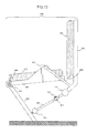
- FIG. 5 is a transparent perspective view of a periphery of the anchor piece 116. This is a drawing in which the periphery of the anchor piece 116 is viewed diagonally from the front and from the lower side of the chair 400.
- the anchor piece 116 is structured in the shape of a plate that projects-cut further forward than the seventh link 202.
- the first stoppers 117 are disposed at the inner side of the seventh link 202, at the upper side of the anchor piece 116.
- the reinforcing plate 115 and peripheral members rotate clockwise as seen from the front surface of FIG. 4 , Accompanying this rotation, the anchor piece 116 similarly rotates clockwise as seen from the front surface of FIG. 4 .
- the range over which the anchor piece 116 can rotate upward in FIG. 5 is limited to up to the position at which the first stoppers 117 exist.
- the relative positional relationships of the first joint portion 103, the second joint portion 104 and the third joint portion 108 are maintained in the same triangular shape by the reinforcing plate 115. Therefore, at the point in time when the anchor piece 116 contacts the first stoppers 117 and rotation is stopped, the reinforcing plate 115 and also the peripheral members that are connected thereto cannot rotate any further upward in FIG. 5 . Accordingly, the sinking-in of the first link 101 and the sixth link 201 stops at that point in time, and the sitting-in position of the user is determined.
- FIGS. 6A and 6B are schematic side views showing states in which the anchor piece 116 and the first stoppers 117 contact, and stop rotation of the reinforcing plate 115 and the peripheral members.
- FIG. 6A shows a state before the user has sat down on the seat surface portion 301.
- the state shown in FIG. 6A is similar to the state of the respective portions shown in FIG. 4 .
- FIG. 6B shows a state in which the user has sat down on the seat surface portion 301, but before the user rests against the back surface portion 302.
- operation of the respective portions will be described.
- the anchor piece 116 rotates clockwise as well.
- the shape of the reinforcing plate 115 is triangular in present exemplary embodiment 3, the shape does not necessarily have to be triangular, and may be an arbitrary shape provided that it can maintain constant the relative positional relationships of the respective portions that it connects.
- the first stoppers 117 are formed of rubber and are solid-cylindrical, from the standpoint of protecting the members and the like, however, the first stoppers 117 do not necessarily have to be solid-cylindrical and rubber, and another member can be used provided that it is a member that can stop the rotation of the anchor piece 116.
- the relative positional relationships of the first joint portion 103, the second joint portion 104 and the third joint portion 108 are maintained constant by using the reinforcing plate 115.
- the second link 102 is pushed downward while the angle between the second link 102 and the fourth link 107 is maintained constant. Therefore, the elastic force of the first elastic resistance unit 105 is applied reliably.
- the anchor piece 116 and the first stoppers 117 are provided, and when the second joint portion 104 rotates clockwise up to a predetermined range, the anchor piece 116 and the first stoppers 117 contact, and restrain rotation.
- a structure is described in which a constant, initial repelling force is imparted in advance upward from beneath the seat surface portion 301, so as to adjust the sitting feeling when the user sits on the seat surface portion 301.
- FIG. 7 is a schematic side view showing the structure of the chair 400 relating to present exemplary embodiment 4.
- the chair 400 relating to present exemplary embodiment 4 has, newly adds a pretensioner 118 and second stoppers 119 onto the structures described in exemplary embodiment 3.
- the other structures are similar- to those of exemplary embodiment 3. Note that some of the reference numerals are omitted from FIG. 7 for convenience of drawing.
- the pretensioner 118 is a mechanism that restrains the second joint portion 104 and the first elastic resistance unit 105 in a state in which they have rotated by a predetermined amount, in a direction of pushing the first link 101 upward (upward in FIG. 7 ).
- a portion of the pretensioner 118 is formed by a projection that projects-cut in the centrifugal direction of the second joint portion 104.
- the remaining portion of the pretensioner 118 pushes this projection by a predetermined amount by using a means such as a push-in screw or the like, from the front surface of the seventh link 202 (the left side as seen from the front surface of FIG. 7 ) toward the rear (the right side as seen from the front surface of FIG. 7 ). Details of the operation of the pretensioner 118 will be described anew in FIGS. 9A and 9B that will be described later.
- the second stoppers 119 are structured by solid-cylindrical rubber pieces and are disposed at the inner side (the right side in FIG. 7 ) of the seventh link 202, at positions supporting the anchor piece 116 from below. Details of the working of the second stoppers 119 will be described anew in FIGS, 9 that will be described later.
- the second stoppers 119 correspond to the "second rotation limiting unit" in present exemplary embodiment 4.
- FIG. 8 is a transparent perspective view of the periphery of the anchor piece 116. This is a drawing in which the periphery of the anchor piece 116 is viewed diagonally from the front and from the lower side of the chair 400.
- the point that the second stoppers 119 are disposed at the lower side of the anchor piece 116 is what is different from FIG. 5 that was described in exemplary embodiment 3. Due to the working of the second stoppers 119, downward rotation of the anchor piece 116 is limited to within a predetermined range.
- FIGS. 9A and 9B are schematic side views showing states in which the anchor piece 116 and the second stoppers 119 contact, and stop rotation of the reinforcing plate 115 and peripheral members.
- FIG. 9A shows a state before the user has sat down on the seat surface portion 301.
- the state shown in FIG. 9A is similar to the state of the respective portions shown in FIG. 7 .
- the operations of the respective portions will be described.
- an initial elastic force is imparted to the first elastic resistance unit 105 by using the pretensioner 118, and force that pushes the first link 101 and the sixth link 201 from beneath is applied. Due thereto, resistance force is applied from beneath at the time when the user sits on the seat surface portion 301, so that he/she attains the sitting feeling.
- the downward rotation of the anchor piece 116 and the peripheral members thereof is limited to within a predetermined range by using the second stoppers 119. Due thereto, even if the pretensioner 118 imparts an initial elastic force to the first elastic resistance unit 105 and causes rotation, the rotation stops in accordance with the position of the second stoppers 119. Therefore, the initial positions of the seat surface portion 301 and the like can be adjusted arbitrarily.
- the initial elastic force of the first elastic resistance unit 105 can be adjusted, and the resistance force at the time when the user sits on the seat surface portion 301 can be adjusted. Due thereto, the sitting feeling of the seat surface portion 301 can be adjusted arbitrarily. Further, because the push-in amount of the push-in screw can be easily adjusted, the user can adjust it by him/herself and can obtain a desired sitting feeling.
- Exemplary embodiment 5 of the present invention describes a structure in which the link mechanism of the chairs 400 described in exemplary embodiments 1 through 4 is simplified. Members that are similar to those described in exemplary embodiments 1 through 4 are denoted by the same reference numerals and description thereof is omitted, and description centers on the points that are different.
- FIG. 10 is a schematic side view showing the structure of the chair 400 relating to present exemplary embodiment 5.
- the chair 400 relating to present exemplary embodiment 5 has structures that are similar to those described in exemplary embodiments 1 through 4. However, as compared with exemplary embodiments 1 through 4, the structure of the link mechanism of the chair 400 is simplified. Further, the second joint portion 104 does not have the first elastic resistance unit 105.
- description will center on the structure of the link mechanism.
- the second joint portion 104 is connected to the seventh link 202 via an appropriate connecting mechanism.
- the distance r1 from the point of intersection between the line that extends from the third link 106 and the seventh link 202 to the fifth joint portion 203, is set longer compared to that in exemplary embodiments 1 through 4.
- a third elastic resistance unit 208 that imparts elastic force in the direction of rotation of the fifth joint portion 203, is provided at the fifth joint portion 203.
- the third elastic resistance unit 208 can be structured by, for example, a torsion spring or the like.
- connection of the eighth link 204, the sixth joint portion 112 and the third link 106 are similar to those in exemplary embodiments 1 through 4.
- the first link 101, the second link 102, the first joint portion 103, the fourth link 107, the third joint portion 108, the fifth link 109 and the fourth joint portion 111 do not exist in present exemplary embodiment 5.
- the structure of the chair 400 can be simplified.
- the structure of the chair 400 relating to present exemplary embodiment 5 has been described above. Next, operations of the respective portions at the time when the user sits on the seat surface portion 301 of the chair 400 will be described.
- FIGS. 11 Athrough 11C are drawings showing changes in respective portions at a time when the user sits on the seat surface portion 301 and rests against the back surface portion 302. Among the respective portions illustrated in FIG. 10 , only the portions that are needed for explanation are selectively illustrated.
- FIG. 11A shows a state before the user sits on the seat surface portion 301.
- the state shown in FIG. 11A is similar to the state of the respective portions shown in FIG 10 .
- FIG. 11B shows a state in which the user has sat down on the seat surface portion 301, but before he/she rests against the back surface portion 302.
- the processes from FIG. 11A to FIG 11B will be described.
- the third link 106 rotates clockwise as seen from the front surface of FIG. 11 , with the second joint portion 104 as the fulcrum. Further, accompanying this, the second joint portion 104 also rotates clockwise.
- the sit-in posture of the user is determined.
- the angle between the sixth link 201 and the eighth link 204 is narrow, and, for the user, there is the effect of the back surface portion 302 automatically approaching his/her back and fitting thereto. Namely, in the same way as in exemplary embodiments 1 through 4, the effect is obtained that the user obtains an optimal seated posture merely by sitting on the seat surface portion 301.
- FIG. 11C shows the state at the time when the user rests against the rear surface portion 302 after having sat on the seat surface portion 301.
- the processes from FIG. 11B to FIG 11C will be described.
- the eighth link 204 rotates clockwise as seen from the front surface of FIG. 11C , with the seventh joint portion 207 being the center of rotation and with the ninth link 206 being the radius.
- FIGS. 12A and 12B the exhibiting of similar effects by the chairs 400 relating to exemplary embodiments 1 through 4 and the chair 400 relating to present exemplary embodiment 5, will be described by using FIGS. 12A and 12B .
- FIGS. 12A and 12B are drawings for explaining differences between, on the one hand, the chairs 400 relating to exemplary embodiments 1 through 4, and, on the other hand, the chair 400 relating to present exemplary embodiment 5.
- FIG. 1 of exemplary embodiment 1 is exemplified in FIG. 12A , but the same holds for exemplary embodiments 2 through 4. Further, for convenience of drawing, the reference numerals of the respective portions are omitted.
- FIG. 12A For comparison, the structure shown in FIG. 1 of exemplary embodiment 1 is shown in FIG 12A , and the structure shown in FIG. 10 of present exemplary embodiment 5 is shown in FIG. 12B .
- r1 in FIG. 12B is determined in accordance with following (formula 1).
- r ⁇ 1 r ⁇ 3 / r ⁇ 4 ⁇ r ⁇ 5
- Present exemplary embodiment 5 describes an example in which the second joint portion 104 does not have the first elastic resistance unit 105, and instead, the third elastic resistance unit 208 is provided at the fifth joint portion 203.
- effects that are similar to those of present exemplary embodiment 5 are exhibited even when employing a structure in which the second joint portion 104 has the first elastic resistance unit 105 in the same way as in exemplary embodiments 1 through 4.
- first elastic resistance unit 105 and the third elastic resistance unit 208 may both be used together.
- the third elastic resistance unit 208 may be provided at the fifth joint portion 203 in the same way as in present exemplary embodiment 5.
- the first elastic resistance unit 105 may be used in combination with the third elastic resistance unit 208. Effects that are similar to exemplary embodiments 1 through 4 can be exhibited also in cases in which these structures are employed.
- the structure of the link mechanism that imparts elastic force to the chair 400 is simplified, and parts costs and the like can be reduced.
- the distance r1 that is explained in FIG. 10 must be able to be made sufficiently large. Therefore, which of the structures of exemplary embodiments 1 through 4 and the structure of exemplary embodiment 5 to employ should be determined appropriately by taking into consideration whether or not there are restrictions thereon, and the like.
- FIG. 13 is a schematic side view showing the structure of the chair 400 relating to exemplary embodiment 6 of the present invention.
- the chair 400 relating to present exemplary embodiment 6 has, in addition to the structures described in exemplary embodiment 5, the second viscous resistance unit 114 that was described in exemplary embodiment 2.
- the other structures thereof are similar to those of exemplary embodiment 5.
- a fourth elastic resistance unit that imparts elastic force in the rotating direction may be provided at the seventh joint portion 207. Due thereto, in addition to the second elastic resistance unit 110, the resistance force at the time when the user rests against the rear surface portion 302 can be adjusted.
- a third viscous resistance unit that, when rotational force is applied to the third elastic resistance unit 208, absorbs the rotational force
- a fourth viscous resistance unit that, when rotational force is applied to the fourth elastic resistance unit, absorbs the rotational force
- the first viscous resistance unit 113 that imparts viscous resistance may be provided at the second joint portion 104.
Abstract
Description
- The present invention relates to a link mechanism for a chair that is used in a chair, and relates to a chair.
- As chairs that are used in offices and the like, there have conventionally been proposed chairs in which, when a user rests against the backrest, i.e., the back surface portion, the seat surface portion operates interlockingly with the back surface portion (see, for example, Japanese Patent Application National Publication No.
2000-505677 4037438 -
FIG. 14 is a drawing showing the structure of a conventional chair. - In
FIG. 14 , 113 is a base portion of a conventional chair. The base portion has supports, casters, and the like that are not illustrated, and is placed on a floor surface, and supports the mass of the entire chair and a user seated on the chair. Aseat surface portion 114, on which a user sits, is rotatably mounted to the upper end of thebase portion 113 via a joint portion. Further, afirst link 112 that supports aback surface portion 115 is rotatably mounted via a joint portion to an intermediate portion of thebase portion 113. Theseat surface portion 114 and thefirst link 112 are connected by asecond link 111 that is rotatably mounted to the both via joint portions. - When a user who is seated on the seat rests against the
back surface portion 115, thefirst link 112 that supports theback surface portion 115 rotates around the joint portion with respect to thebase portion 113. Further, because theseat surface portion 114 is connected to thefirst link 112 by thesecond link 111, interlockingly with thefirst link 112, theseat surface portion 114 rotates around the joint portion with respect to thebase portion 113. - However, in the above-described conventional chair, the
seat surface portion 114 does not operate unless force is applied to theback surface portion 115, and therefore, the user cannot always assume an optimal seated posture. - Namely, the
seat surface portion 114 does not operate if the user who is seated on theseat surface portion 114 does not tilt his/her back more than the angle of inclination of theback surface portion 115 with respect to theseat surface portion 114 in the initial state. Accordingly, in a case in which the user who is seated on theseat surface portion 114 does not rest against theback surface portion 115, such as, for example, a case in which the user is working while facing his/her desk, the angle of theseat surface portion 114 does not change. Therefore, the user cannot always assume an optimal seated posture. For example, when the user is seated with a forward-leaning posture so as to face a desk, the user is not resting against theback surface portion 115, and thus, theback surface portion 115 does not fit the lumbar region, and the posture of the person who is seated deteriorates. - Thus, a construction that is such that the user of a chair can always assume an optimal seated posture is desired.
- A chair relating to an aspect of the present invention has: a seat surface portion; a back surface portion; a sixth link that supports the seat surface portion; an eighth link that supports the back surface portion; a third link whose one end is connected to the eighth link; a first link whose one end is connected to a bottom surface of the sixth link; a second link whose one end is connected to another end of the first link; a fourth link whose one end is connected to another end of the second link, and whose other end is connected to another end of the third link; a seventh link that is connected directly or indirectly to the other end of the second link; a fifth link whose one end is connected to the other end of the first link and the one end of the second link, and whose other end is connected to the other end of the third link and the other end of the fourth link; a first joint portion that is provided at a connected portion of the other end of the first link, the one end of the second link and the one end of the fifth link, and that rotatably connects these links; a second joint portion that is provided at the seventh link, and that is provided at a connected portion of the other end of the second link and the one end of the fourth link, and that rotatably connects these links; a third joint portion that is provided at a connected portion of the other end of the third link, the other end of the fourth link and the other end of the fifth link, and that rotatably connects these links; a fourth joint portion that is provided at a connected portion of the bottom surface of the sixth link and the one end of the first link, and that rotatably connects these links; a fifth joint portion that is provided at a connected portion of the sixth link and the seventh link, and that rotatably connects these links; a sixth joint portion that is provided at a connected portion of the one end of the third link and the eighth link, and that rotatably connects these links; a seventh joint portion that directly or indirectly connects the sixth link and the eighth link, and that rotatably connects the sixth link and the eighth link; and a first elastic resistance unit that, at the second joint portion, when the seat surface portion is pushed, imparts elastic force in a direction opposite to a direction in which the second link rotates due to the pushing force.
- The above-described chair may have the feature that, when the seat surface portion is pushed, the second link, the fourth link and the fifth link rotate with the second joint portion being a center of rotation, and due to the third link being pushed by the rotation, the eighth link is pushed rearward and rotates with the seventh joint portion being a center of rotation, and an angle between the seat surface portion and the back surface portion narrows.
- The above-described chair may have the feature of having: a ninth link whose one end is rotatably connected to the seventh joint portion, and whose other end is connected to the eighth link, wherein the sixth link and the ninth link are structured so as to dispose the seventh joint portion at a position that is apart, by a predetermined distance forward, from the eighth link.
- The above-described chair may have the feature of having: a second elastic resistance unit that, when compressive force is imparted to the third link, imparts elastic force in a direction opposite the compressive force.
- The above-described chair may have the feature of having: a first viscous resistance unit that imparts viscous resistance to the second joint portion.
- The above-described chair may have the feature of having: a second viscous resistance unit that, when compressive force is imparted to the third link, buffers the compressive force.
- The above-described chair may have the feature of having: a first rotation limiting unit that limits, to within a predetermined range, a range over which the second link rotates at the second joint portion when the seat surface portion is pushed.
- The above-described chair may have the feature that the first rotation limiting unit has: an anchor piece that rotates interlockingly with rotation of the second link, the fourth link and the fifth link; and a first stopper that is provided at the seventh link, and due to the anchor piece contacting the first stopper, the first rotation limiting unit limits, to within a predetermined range, a range over which the second link rotates at the second joint portion when the seat surface portion is pushed.
- The above-described chair may have the feature of having: in addition to the first elastic resistance unit, a third elastic resistance unit that imparts elastic force in a rotating direction to the fifth joint portion.
- The above-described chair may have the feature of having: a unit that imparts pretension to the first elastic resistance unit.
- The above-described chair may have the feature of having: a unit that imparts pretension to the first elastic resistance unit; and a second rotation limiting unit that limits, to within predetermined ranges, ranges over which the second link, the fourth link and the fifth link rotate in a direction opposite to a direction in which the second link rotates at the second joint portion when the seat surface portion is pushed.
- The above-described chair may have the feature that the second rotation limiting unit has: a second stopper that is provided at the seventh link, and due to the anchor piece contacting the second stopper, the second rotation limiting unit limits, to within predetermined ranges, ranges over which the second link, the fourth link and the fifth link rotate in a direction opposite to a direction in which the second link rotates at the second joint portion when the seat surface portion is pushed.
- A link mechanism for a chair that is used in a chair and that relates to an aspect of the present invention has at least: a sixth link that supports a seat surface portion; an eighth link that supports a back surface portion; a third link whose one end is connected to the eighth link; a first link whose one end is connected to a bottom surface of the sixth link; a second link whose one end is connected to another end of the first link; a fourth link whose one end is connected to another end of the second link, and whose other end is connected to another end of the third link; a seventh link that is connected directly or indirectly to the other end of the second link; a fifth link whose one end is connected to the other end of the first link and the one end of the second link, and whose other end is connected to the other end of the third link and the other end of the fourth link; a first joint portion that is provided at a connected portion of the other end of the first link, the one end of the second link and the one end of the fifth link, and that rotatably connects these links; a second joint portion that is provided at the seventh link, and that is provided at a connected portion of the other end of the second link and the one end of the fourth link, and that rotatably connects these links; a third joint portion that is provided at a connected portion of the other end of the third link, the other end of the fourth link and the other end of the fifth link, and that rotatably connects these links; a fourth joint portion that is provided at a connected portion of the bottom surface of the sixth link and the one end of the first link, and that rotatably connects these links; a fifth joint portion that is provided at a connected portion of the sixth link and the seventh link, and that rotatably connects these links; a sixth joint portion that is provided at a connected portion of the one end of the third link and the eighth link, and that rotatably connects these links; a seventh joint portion that directly or indirectly connects the sixth link and the eighth link, and that rotatably connects the sixth link and the eighth link; and a first elastic resistance unit that, at the second joint portion, when the seat surface portion is pushed, imparts elastic force in a direction opposite to a direction in which the second link rotates due to the pushing force.
- The above-described link mechanism for a chair may have the feature that, when the sixth link is pushed, the second link, the fourth link and the fifth link rotate with the second joint portion being a center of rotation, and the eighth link, due to the third link being pushed by the rotation, rotates with the seventh joint portion being a center of rotation, and rotates in a direction in which an angle between the sixth link and the eighth link narrows.
- The above-described link mechanism for a chair may have the feature of having: a ninth link whose one end is rotatably connected to the seventh joint portion, and whose other end is connected to the eighth link, wherein the sixth link and the ninth link are structured so as to dispose the seventh joint portion at a position that is apart, by a predetermined distance forward, from the eighth link,
- A chair relating to an aspect of the present invention has: a seat surface portion; a back surface portion; a sixth link that supports the seat surface portions; an eighth link that supports the back surface portion; a third link whose one end is connected to the eighth link; a seventh link that is connected to another end of the third link; a second joint portion that is provided at the seventh link, and to which the other end of the third link is rotatably connected; a fifth joint portion that rotatably connects the sixth link and the seventh link; a sixth joint portion that rotatably connects the third link and the eighth link; a second elastic resistance unit that, when compressive force is imparted to the third link, imparts elastic force in a direction opposite the compressive force; and a third elastic resistance unit that imparts elastic force in a rotating direction to the fifth joint portion.
- The above-described chair may have the feature of having a seventh joint portion that rotatably connects the sixth link and the eighth link.
- The above-described chair may have the feature of having: a ninth link whose one end is connected to the sixth link and whose other end is connected to the eighth link; and a seventh joint portion that rotatably connects the sixth link and the ninth link, wherein the sixth link and the ninth link are structured so as to dispose the seventh joint portion at a position that is apart, by a predetermined distance forward, from the eighth link.
- The above-described chair may have the feature of having: in addition to the third elastic resistance unit, a first elastic resistance unit that imparts elastic force in a rotating direction to the second joint portion.
- The above-described chair may have the feature of having: a first viscous resistance unit that imparts viscous resistance to the second joint portion,
- The above-described chair may have the feature of having: a third viscous resistance unit that that imparts viscous resistance to the fifth joint portion.
- The above-described chair may have the feature of having: a second viscous resistance unit that, when compressive force is imparted to the third link, buffers the compressive force.
- The above-described chair may have the feature of having: fourth elastic resistance unit for imparting elastic force in a rotating direction to the seventh joint portion.
- The above-described chair may have the feature of having: fourth viscous resistance unit for imparting viscous resistance to the seventh joint portion.
- A chair relating to an aspect of the present invention has: a seat surface portion; a back surface portion; a sixth link that supports the seat surface portion; an eighth link that supports the back surface portion; a third link whose one end is connected to the eighth link; a first link whose one end is connected to a bottom surface of the sixth link; a second link whose one end is connected to another end of the first link; a fourth link whose one end is connected to another end of the second link, and whose other end is connected to another end of the third link; a seventh link that is connected directly or indirectly to the other end of the second link; a fifth link whose one end is connected to the other end of the first link and the one end of the second link, and whose other end is connected to the other end of the third link and the other end of the fourth link; a first joint portion that is provided at a connected portion of the other end of the first link, the one end of the second link and the one end of the fifth link, and that rotatably connects these links; a second joint portion that is provided at the seventh link, and that is provided at a connected portion of the other end of the second link and the one end of the fourth link, and that rotatably connects these Links; a third joint portion that is provided at a connected portion of the other end of the third link, the other end of the fourth link and the other end of the fifth link, and that rotatably connects these links; a fourth joint portion that is provided at a connected portion of the bottom surface of the sixth link and the one end of the first link, and that rotatably connects these links; a fifth joint portion that is provided at a connected portion of the sixth link and the seventh link, and that rotatably connects these links; a sixth joint portion that is provided at a connected portion of the one end of the third link and the eighth link, and that rotatably connects these links; a seventh joint portion that directly or indirectly connects the sixth link and the eighth link, and that rotatably connects the sixth link and the eighth link; and a third elastic resistance unit that imparts elastic force in a rotating direction to the fifth joint portion.
- A chair relating to an aspect of the present invention has: a seat surface portion; a back surface portion; a sixth link that supports the seat surface portion; an eighth link that supports the back surface portion; a third link whose one end is connected to the eighth link; a seventh link that is connected to another end of the third link; a second joint portion that is provided at the seventh link, and to which the other end of the third link is rotatably connected; a fifth joint portion that rotatably connects the sixth link and the seventh link; a sixth joint portion that rotatably connects the third link and the eighth link; a second elastic resistance unit that, when compressive force is imparted to the third link, imparts elastic force in a direction opposite the compressive force; and a first elastic resistance unit that imparts elastic force in a rotating direction to the second joint portion.
- In accordance with a link mechanism for a chair relating to an aspect of the present invention, when a user sits down, a first link is pushed by a seat surface portion, and elastic force of a first elastic resistance unit is applied. Due thereto, a user can assume an optimal seated posture without pushing a back rest.
- Preferred exemplary embodiments of the present invention will be described in detail based on the following figures, wherein:
-
FIG. 1 is a schematic side view showing the structure of achair 400 relating toexemplary embodiment 1; -
FIG. 2A is a drawing showing states of respective portions before a user sits on aseat surface portion 301; -
FIG. 2B is a drawing showing states of respective portions at a time when a user sits on aseat surface portion 301 and before he/she rests against aback surface portion 302; -
FIG 2C is a drawings showing states of respective portions at a time when a user sits on aseat surface portion 301 and rests against aback surface portion 302; -
FIG. 3 is a schematic side view showing the structure of thechair 400 relating to exemplary embodiment 2; -
FIG. 4 is a schematic side view showing the structure of thechair 400 relating to exemplary embodiment 3; -
FIG. 5 is a transparent perspective view of the periphery of ananchor piece 116; -
FIG. 6A is a schematic side views showing states in which theanchor piece 116 andfirst stoppers 117 contact, and stop rotation of a reinforcingplate 115 and peripheral members, and shows a state before a user sits on aseat surface portion 301; -
FIG. 6B is a schematic side views showing states in which theanchor piece 116 and first stoppers 117 contact, and stop rotation of a reinforcingplate 115 and peripheral members, and shows a state when a user sits on aseat surface portion 301 and before he/she rests against aback surface portion 302; -
FIG. 7 is a schematic side view showing the structure of thechair 400 relating to exemplary embodiment 4; -
FIG. 8 is a transparent perspective view of the periphery of theanchor piece 116; -
FIG. 9A is a schematic side views showing states in which theanchor piece 116 andsecond stoppers 119 contact, and stop rotation of the reinforcingplate 115 and peripheral members, and shows a state before a user sits on aseat surface portion 301; -
FIG. 9B is a schematic side views showing states in which theanchor piece 116 andsecond stoppers 119 contact, and stop rotation of the reinforcingplate 115 and peripheral members, and shows a state when a user sits on aseat surface portion 301 and before he/she rests against aback surface portion 302; -
FIG 10 is a schematic side view showing the structure of thechair 400 relating to exemplary embodiment 5; -
FIG. 11A is a drawing showing states of respective portions at a time before a user sits on theseat surface portion 301; -
FIG. 11B is a drawing showing states of respective portions at a time when a user sits on theseat surface portion 301 and before he/she rests against theback surface portion 302; -
FIG. 11C is a drawing showing states of respective portions at a time when a user sits on theseat surface portion 301 and rests against theback surface portion 302; -
FIG. 12A is a drawing showing structures of thechairs 400 relating toexemplary embodiments 1 through 4; -
FIG. 12B is a drawing showing structure of thechair 400 relating to exemplary embodiment 5; -
FIG. 13 is a schematic side view showing the structure of thechair 400 relating to exemplary embodiment 6; and -
FIG. 14 is a drawing showing the structure of a conventional chair. -
FIG. 1 is a schematic side view showing the structure of achair 400 relating toexemplary embodiment 1 of the present invention. Here, only portions that are necessary for explaining the structure of thechair 400 are illustrated. Hereinafter, first, the overall structure of thechair 400 will be described, and thereafter, details of the link mechanism of thechair 400 will be explained. - The
chair 400 has aseat surface portion 301 and aback surface portion 302. Theseat surface portion 301 is fixed on asixth link 201 that will be described later. Theback surface portion 302 is fixed on aneighth link 204 that will be described later. - The
sixth link 201 supports theseat surface portion 301 from below, and is connected to aseventh link 202 that will be described later via a fifthjoint portion 203 that will be described later. Further, the portion of thesixth link 201 that corresponds to the side surface of a user who is seated on theseat surface portion 301 rises upwardly. This upwardly-rising portion is connected to theeighth link 204 via aninth link 206 that will be described later. - The
seventh link 202 functions as a base portion that supports the self-weight of thechair 400 and the body weight of the user who is seated on theseat surface portion 301. A base portion may be provided separately from theseventh link 202, and connected to theseventh link 202. The fifthjoint portion 203 is structured by, for example, a hinge joint, and rotatably connects thesixth link 201 and theseventh link 202. The fifthjoint portion 203 does not have means for imparting elastic force, such as a rotary spring or the like. The body weight of the user who is seated on theseat surface portion 301 is supported by the link mechanism that will be described later imparting elasticity to thechair 400. - The
eighth link 204 is disposed at the rear of theback surface portion 302, and, via theback surface portion 302 and from the rear, supports the back of the user who is seated on theseat surface portion 301. Theeighth link 204 is connected, via theninth link 206 that will be described later, to thesixth link 201 at a position corresponding to the side surface of the user. Moreover, theeighth link 204 is connected to athird link 106 that will be described later via a sixthjoint portion 112 that will be described later. - The
ninth link 206 is fixedly connected to theeighth link 204. Theninth link 206 is connected to thesixth link 201 via a seventhjoint portion 207 that will be described hereinafter. The seventhjoint portion 207 is structured by a hinge joint for example, and rotatably connects thesixth link 201 and theninth link 206. - Due to the structure of the above-described
sixth link 201 andninth link 206, the seventhjoint portion 207 is disposed at a position that is apart, by a predetermined distance forward, from theeighth link 204 and theback surface portion 302. The position of the seventhjoint portion 207 approximately corresponds to the position of the hip joint of the user when the user is seated on theseat surface portion 301. - The overall structure of the
chair 400 has been described above. Next, the link mechanism of thechair 400 will be described. - The bottom surface of the
sixth link 201 is supported from beneath at afirst link 101. One end of thefirst link 101 and thesixth link 201 are connected at a fourthjoint portion 111. The fourthjoint portion 111 is structured by a hinge joint for example, and rotatably connects the bottom surface side of thefirst link 101 and thesixth link 201. - A
second link 102 is connected via a firstjoint portion 103 to the other end of thefirst link 101. One end of thesecond link 102 is connected to the firstjoint portion 103, and the other end is connected to a secondjoint portion 104 that will be described hereinafter. - The second
joint portion 104 is connected to the aforementionedseventh link 202 via an appropriate connecting mechanism. A firstelastic resistance unit 105, that imparts elastic force in a rotating direction to the secondjoint portion 104, is provided at the secondjoint portion 104. The firstelastic resistance unit 105 can be structured by, for example, a torsion spring or the like. - The
third link 106 is rotatably connected to the above-describedeighth link 204 via the sixthjoint portion 112 that will be described later. Thethird link 106 is disposed beneath thesixth link 201, substantially parallel to thesixth link 201. One end of thethird link 106 is connected to theeighth link 204 via the sixthjoint portion 112. Further, thethird link 106 functions to push the eighth link rightward inFIG. 1 (in the direction of the back surface of the user), due to the repelling elastic force imparted by a secondelastic resistance unit 110 that will be described hereinafter. The secondelastic resistance unit 110 is structured by, for example, a repulsion spring or the like, and imparts repelling elastic force to thethird link 106, and functions to push the eighth link rightward inFIG. 1 . The specific operation will be described inFIG. 2 that will be explained later. - The sixth
joint portion 112 is structured by a hinge joint for example, and rotatably connects theeighth link 204 and thethird link 106. - A third
joint portion 108 is provided at the other end of thethird link 106. The thirdjoint portion 108 and the secondjoint portion 104 are connected by afourth link 107. The thirdjoint portion 108 and the firstjoint portion 103 are connected by afifth link 109. - The link mechanism of the
chair 400 has been described above. Next, operation of the respective portions when a user sits on theseat surface portion 301 of thechair 400 will be described. -
FIGS. 2A through 2C are drawings showing changes in the respective portions at a time when a user sits on theseat surface portion 301 and rests against theback surface portion 302. Here, among the respective portions shown inFIG. 1 , only the portions that are needed for explanation are selectively illustrated. -
FIG. 2A shows a state before the user sits on theseat surface portion 301. The state shown inFIG. 2A is similar to the state of the respective portions shown inFIG. 1 . -
FIG. 2B shows a state when the user sits on theseat surface portion 301, and before he/she rests against theback surface portion 302. The processes fromFIG. 2A to FIG. 2B will be described hereinafter. - (1) When the user sits on the
seat surface portion 301, thesixth link 201 rotates with the fifthjoint portion 203 being the fulcrum, so as to sink-in. At this time, thefirst link 101 that supports the bottom surface side of thesixth link 201 is pushed downward. - (2) The
first link 101 pushes the firstjoint portion 103 downward. - (3) Accompanying the first
joint portion 103 being pushed downward, thesecond link 102 rotates downward around the secondjoint portion 104. Further, the secondjoint portion 104 rotates clockwise as seen from the front surface ofFIG. 2 . - (4) When the second
joint portion 104 rotates clockwise, the elastic force of the firstelastic resistance unit 105 repels this and works counterclockwise, and elastic force in a direction of pushing thesecond link 102 and thefirst link 101 upward is applied. - (5) At the point in time when the body weight of the user and this elastic force are in equilibrium, the rotation of the
sixth link 201 stops, and the sinking-in of theseat surface portion 301 stops. At this point in time, the sit-in posture of the user is determined. - (6) On the other hand, accompanying the first
joint portion 103 being pushed downward, the thirdjoint portion 108, thefourth link 107, and thefifth link 109 receive rotational force in the clockwise direction, as seen from the front surface ofFIG. 2 , around the secondjoint portion 104. - (7) Accompanying the third
joint portion 108 and the like rotating clockwise around the secondjoint portion 104, thethird link 106 pushes the sixthjoint portion 112 and theeighth link 204 rearward. Accompanying this, theeighth link 204 rotates counterclockwise inFIG. 2B around the seventhjoint portion 207. Further, the angle between thesixth link 201 and theeighth link 204 narrows. Due thereto, for the user who is seated on theseat surface portion 301, there is the effect of theback surface portion 302 approaching his/her back and automatically fitting thereto. Namely, merely by sitting on theseat surface portion 301, the user obtains an optimal seated posture, and does not need to push theback surface portion 302 in order to adjust the seated posture. - The operations of the respective portions at the time when the user sits on the
seat surface portion 301 have been described above. -
FIG. 2C shows a state at the time when the user rests against theback surface portion 302, after having sat on theseat surface portion 301. Hereinafter, the processes fromFIG. 2B to FIG. 2C will be described. - (8) When the user rests against the
back surface portion 302, theeighth link 204 is, with the seventhjoint portion 207 being the center of rotation, supported by theninth link 206 and rotates clockwise as seen from the front surface ofFIG. 2C . - (9) When the
eighth link 204 rotates clockwise, the sixthjoint portion 112 is pushed substantially leftward (in the direction of the front surface of the user) as seen from the front surface ofFIG. 2 . - (10) Accompanying this, the second
elastic resistance unit 110 is pushed, and repelling elastic force toward the right inFIG. 2 (in the direction of the back surface of the user) is generated. - (11) At the point in time when the force at which the user rests against the
back surface portion 302 and this repelling elastic force are in equilibrium, the tilting of theeighth link 204 stops, and the back-resting posture of the user is determined. - (12) Note that, in the state of
FIG. 2B , when the user sits on theseat surface portion 301, if he/she sits-in in a state in which his/her back contacts theback surface portion 302, the force by which the back of the user pushes theback surface portion 302 and the force by which thethird link 106 pushes theeighth link 204 oppose one another, and the secondelastic resistance unit 110 is compressed. At the point in time when the force by which the elastic force or the like, that is generated at the secondelastic resistance unit 110 due thereto, pushes theeighth link 204 rearward and the force by which the back of the user pushes theback surface portion 302 are in equilibrium, the position of theback surface portion 302, i.e., the seated posture of the user, is determined. - (13) Further, there can be a structure in which the coefficient of elasticity of the second
elastic resistance unit 110 is adjusted, and thethird link 106 is pushed leftward inFIG. 2 when the user rests against theback surface portion 302. In this case, rotational force works in the direction of thefirst link 101 pushing thesixth link 201 upward from beneath, and theback surface portion 302 and theseat surface portion 301 operate interlockingly. - The operations of the respective portions at the time when the user sits on the
seat surface portion 301 of thechair 400 have been described above. Note that, from the standpoint of ease of explanation, inFIGS. 1 and2A through 2C , the link mechanism is drawn so as to be able to be seen from the side surface of thechair 400. However, as needed, the link mechanism may be covered by a casing or the like such that the user cannot see the mechanism portions. - Further, the link mechanism may be formed as a module such that it can be removed from the
chair 400, and can be structured such that designing, production, repair, replacement and the like can be carried out with the link mechanism for a chair being a single unit. The link mechanism for a chair can include thesixth link 201, theseventh link 202 and other peripheral members. Which peripheral parts should be included in the link mechanism for a chair may be determined appropriately in accordance with the extent to which the link mechanism for a chair is formed as a module, and the like. - As described above, in the
chair 400 relating toexemplary embodiment 1, as explained inFIGS. 2B through. 2C , theseat surface portion 301 and theback surface portion 302 change interlockingly accompanying the sitting of the user. Accordingly, the user can always assume an optimal seated posture. - Further, the
chair 400 relating to presentexemplary embodiment 1 has, beneath theseat surface portion 301, the link mechanism that is described inFIG. 1 andFIGS. 2B through 2C . By adjusting the coefficients of elasticity of the firstelastic resistance unit 105 and the secondelastic resistance unit 110 that are provided at the link mechanism, the strengths of the forces needed when theseat surface portion 301 is sunk-in and theback surface portion 302 is inclined can be adjusted. Due thereto, the seating comfort and the feeling of use of thechair 400 can be adjusted arbitrarily. - Further, at the
chair 400 relating to presentexemplary embodiment 1, theeighth link 204 rotates around the seventhjoint portion 207. Because the seventhjoint portion 207 is at a position that approximately corresponds to the hip joint of the user who sits on theseat surface portion 301, theeighth link 204 and theback surface portion 302 can be rotated around the hip joint of the user. Therefore, the rotating operation of theback surface portion 302 is made to appropriately suit the body structure of the user, and can provide a good sitting feeling. -
FIG. 3 is a schematic side view showing the structure of thechair 400 relating to exemplary embodiment 2 of the present invention. Thechair 400 relating to present exemplary embodiment 2 is equipped with a firstviscous resistance unit 113 that imparts viscous resistance to the secondjoint portion 104, and a secondviscous resistance unit 114 that imparts viscous resistance to thethird link 106. Because the other structures are similar to those described inFIG. 1 ofexemplary embodiment 1, description hereinafter will center on the points that differ. - The first
viscous resistance unit 113 has the function of, when rotational force is applied to the firstelastic resistance unit 105, damping the rotational force. The secondviscous resistance unit 114 has the function of, when pushing force is applied to the secondelastic resistance unit 110, damping the pushing force. - The first
viscous resistance unit 113 and the secondviscous resistance unit 114 can be structured by oil-type shock absorbers for example. - The first
viscous resistance unit 113 and the secondviscous resistance unit 114 can be structured as portions of the link mechanism for a chair described inexemplary embodiment 1. - Because the
chair 400 relating to present exemplary embodiment 2 is equipped with the firstviscous resistance unit 113, the sinking-in at the time when the user sits on theseat surface portion 301 can be made to be gentle, and a soft sitting-in feeling can be provided. - Further, because the
chair 400 relating to present exemplary embodiment 2 is equipped with the secondviscous resistance unit 114, the falling-in at the time when the user rests against theback surface portion 302 can be made to be gentle, and a soft back-resting feeling can be provided. -
Exemplary embodiments 1 and 2 are structured such that, by using the elastic force that the firstelastic resistance unit 105 imparts to the secondjoint portion 104, an upward repelling force is imparted to theseat surface portion 301, and theseat surface portion 301 resists the body weight of the user. However, at a time when a very heavy object is placed on theseat surface portion 301, or the like, there is the possibility that the elastic force of the firstelastic resistance unit 105 cannot withstand this, and the secondjoint portion 104 and the like rotate past the allowable range of rotation and break. Thus, in exemplary embodiment 3 of the present invention, a structure is described that limits the range of downward sinking-in of thesixth link 201 and the like to a given range. -
FIG. 4 is a schematic side view showing the structure of thechair 400 relating to present exemplary embodiment 3. Thechair 400 relating to present exemplary embodiment 3 is equipped with, in addition to the structures described inexemplary embodiments 1 and 2, a reinforcingplate 115, andanchor piece 116 andfirst stoppers 117. The other structures are similar toexemplary embodiments 1 and 2. Note thatFIG. 4 illustrates an example that has the aforementioned respective portions in addition to the structure ofFIG. 1 that was described inexemplary embodiment 1. Hereinafter, the aforementioned respective portions are described by usingFIG. 4 . - The reinforcing
plate 115 fills-in the triangular space that is formed between thesecond link 102, thefourth link 107 and thefifth link 109, and maintains constant the relative positional relationships of these three links. At the same time, the relative positional relationships of the firstjoint portion 103, the secondjoint portion 104 and the thirdjoint portion 108 are always maintained the same by the reinforcingplate 115. Due thereto, even when the user sits on theseat surface portion 301 and the aforementioned respective links and respective joint portions rotate, the relative positional relationships of the firstjoint portion 103, the secondjoint portion 104 and the thirdjoint portion 108 are maintained in the same triangular shape. - The
anchor piece 116 is structured as a plate-shaped member that projects-out from the thirdjoint portion 108 toward the front of thechair 400. Details thereof are described anew inFIG.5 that will be described later. Thefirst stoppers 117 are structured by solid-cylindrical rubber pieces, and are disposed at the inner side (the right side inFIG. 4 ) of theseventh link 202, at the upper side of theanchor piece 116. - The reinforcing
plate 115 corresponds to the "relative position fixing mechanism" in present exemplary embodiment 3. Further, theanchor piece 116 corresponds to the "first rotation limiting unit",FIG. 5 is a transparent perspective view of a periphery of theanchor piece 116. This is a drawing in which the periphery of theanchor piece 116 is viewed diagonally from the front and from the lower side of thechair 400. Theanchor piece 116 is structured in the shape of a plate that projects-cut further forward than theseventh link 202. Thefirst stoppers 117 are disposed at the inner side of theseventh link 202, at the upper side of theanchor piece 116. - When the user sits on the
seat surface portion 301, the reinforcingplate 115 and peripheral members rotate clockwise as seen from the front surface ofFIG. 4 , Accompanying this rotation, theanchor piece 116 similarly rotates clockwise as seen from the front surface ofFIG. 4 . However, because thefirst stoppers 117 are disposed above and below theanchor piece 116, the range over which theanchor piece 116 can rotate upward inFIG. 5 is limited to up to the position at which thefirst stoppers 117 exist. - On the other hand, the relative positional relationships of the first
joint portion 103, the secondjoint portion 104 and the thirdjoint portion 108 are maintained in the same triangular shape by the reinforcingplate 115. Therefore, at the point in time when theanchor piece 116 contacts thefirst stoppers 117 and rotation is stopped, the reinforcingplate 115 and also the peripheral members that are connected thereto cannot rotate any further upward inFIG. 5 . Accordingly, the sinking-in of thefirst link 101 and thesixth link 201 stops at that point in time, and the sitting-in position of the user is determined. -
FIGS. 6A and6B are schematic side views showing states in which theanchor piece 116 and thefirst stoppers 117 contact, and stop rotation of the reinforcingplate 115 and the peripheral members. -
FIG. 6A shows a state before the user has sat down on theseat surface portion 301. The state shown inFIG. 6A is similar to the state of the respective portions shown inFIG. 4 . -
FIG. 6B shows a state in which the user has sat down on theseat surface portion 301, but before the user rests against theback surface portion 302. Hereinafter, operation of the respective portions will be described. - (1) When the user sits down on the
seat surface portion 301, as explained inFIG. 2B , the respective structural members such as the firstjoint portion 103, the secondjoint portion 104, the thirdjoint portion 108 and the like rotate clockwise as seen from the front surface ofFIG. 6B . At this time, the relative positional relationships of the respective structural members are maintained in a fixed triangular shape by the reinforcing plate 15. - (2) Accompanying the rotation of the respective structural members, the
anchor piece 116 rotates clockwise as well. - (3) When the respective structural members and the
anchor piece 116 rotate a given extent, theanchor piece 116 contacts the first stoppers 17. - (4) Due to the working of the
anchor piece 116 and the first stoppers, the respective structural members cannot rotate any further clockwise. - (5) Accordingly, the sinking-in of the
seat surface portion 301 as well stops at that point in time. - The working of the
anchor piece 116 and thefirst stoppers 117 have been described above. Note that, although the shape of the reinforcingplate 115 is triangular in present exemplary embodiment 3, the shape does not necessarily have to be triangular, and may be an arbitrary shape provided that it can maintain constant the relative positional relationships of the respective portions that it connects. Further, in present exemplary embodiment 3, thefirst stoppers 117 are formed of rubber and are solid-cylindrical, from the standpoint of protecting the members and the like, however, thefirst stoppers 117 do not necessarily have to be solid-cylindrical and rubber, and another member can be used provided that it is a member that can stop the rotation of theanchor piece 116. - As described above, in present exemplary embodiment 3, the relative positional relationships of the first
joint portion 103, the secondjoint portion 104 and the thirdjoint portion 108 are maintained constant by using the reinforcingplate 115. Thus, when the user sits on theseat surface portion 301, thesecond link 102 is pushed downward while the angle between thesecond link 102 and thefourth link 107 is maintained constant. Therefore, the elastic force of the firstelastic resistance unit 105 is applied reliably. - Further, in present exemplary embodiment 3, the
anchor piece 116 and thefirst stoppers 117 are provided, and when the secondjoint portion 104 rotates clockwise up to a predetermined range, theanchor piece 116 and thefirst stoppers 117 contact, and restrain rotation. - Therefore, even in a case in which, for example, a very heavy object is placed on the
seat surface portion 301, there is no concern that the respective portions will rotate past the allowable range and break or the like. - In exemplary embodiment 4 of the present invention, a structure is described in which a constant, initial repelling force is imparted in advance upward from beneath the
seat surface portion 301, so as to adjust the sitting feeling when the user sits on theseat surface portion 301. -
FIG. 7 is a schematic side view showing the structure of thechair 400 relating to present exemplary embodiment 4. Thechair 400 relating to present exemplary embodiment 4 has, newly adds apretensioner 118 andsecond stoppers 119 onto the structures described in exemplary embodiment 3. The other structures are similar- to those of exemplary embodiment 3. Note that some of the reference numerals are omitted fromFIG. 7 for convenience of drawing. - The
pretensioner 118 is a mechanism that restrains the secondjoint portion 104 and the firstelastic resistance unit 105 in a state in which they have rotated by a predetermined amount, in a direction of pushing thefirst link 101 upward (upward inFIG. 7 ). A portion of thepretensioner 118 is formed by a projection that projects-cut in the centrifugal direction of the secondjoint portion 104. The remaining portion of thepretensioner 118 pushes this projection by a predetermined amount by using a means such as a push-in screw or the like, from the front surface of the seventh link 202 (the left side as seen from the front surface ofFIG. 7 ) toward the rear (the right side as seen from the front surface ofFIG. 7 ). Details of the operation of thepretensioner 118 will be described anew inFIGS. 9A and9B that will be described later. - The
second stoppers 119 are structured by solid-cylindrical rubber pieces and are disposed at the inner side (the right side inFIG. 7 ) of theseventh link 202, at positions supporting theanchor piece 116 from below. Details of the working of thesecond stoppers 119 will be described anew inFIGS, 9 that will be described later. - The
second stoppers 119 correspond to the "second rotation limiting unit" in present exemplary embodiment 4. -
FIG. 8 is a transparent perspective view of the periphery of theanchor piece 116. This is a drawing in which the periphery of theanchor piece 116 is viewed diagonally from the front and from the lower side of thechair 400. The point that thesecond stoppers 119 are disposed at the lower side of theanchor piece 116 is what is different fromFIG. 5 that was described in exemplary embodiment 3. Due to the working of thesecond stoppers 119, downward rotation of theanchor piece 116 is limited to within a predetermined range. -
FIGS. 9A and9B are schematic side views showing states in which theanchor piece 116 and thesecond stoppers 119 contact, and stop rotation of the reinforcingplate 115 and peripheral members. -
FIG. 9A shows a state before the user has sat down on theseat surface portion 301. The state shown inFIG. 9A is similar to the state of the respective portions shown inFIG. 7 . Hereinafter, the operations of the respective portions will be described. - (1) When the push-in screw portion of the
pretensioner 118 is pushed-in toward the right inFIG. 9A , the push-in screw pushes the projecting portion that projects from the secondjoint portion 104, and rotational force in the direction of pushing thefirst link 101 upward is applied. - (2) As a result, pressure is applied in the directions shown by the arrows in
FIG. 9A , and force is applied in a direction of pushing thefirst link 101 upward from below. Therefore, when the user sits on theseat surface portion 301, a constant resistance force is applied from beneath, Therefore, by adjusting this resistance force, the sitting feeling can be adjusted. - (3) When pressure is applied in the directions shown by the arrows in
FIG. 9A due to the working of thepretensioner 118, theanchor piece 116 and peripheral members thereof rotate downward (counterclockwise as seen from the front surfaces ofFIG. 9A ). In order to keep this rotation within a predetermined range, thesecond stoppers 119 are disposed at the appropriate position, and are made to contact theanchor piece 116. - (4) At the point in time when the
anchor piece 116 and thesecond stoppers 119 contact, rotation of theanchor piece 116 and the peripheral members thereof stops. At this point in time, the positions of thesixth link 201 and theseat surface portion 301 and the like are determined. - (5) When the push-in screw portion of the
pretensioner 118 is pushed-in further, theanchor piece 116 and the peripheral members thereof do not rotate any further, but the firstelastic resistance unit 105 is pushed further. Therefore, the repelling elastic force of the firstelastic resistance unit 105 increases, and the force that pushes theseat surface portion 301 upward from beneath via thefirst link 101 and thesixth link 201 at the time when the user sits on theseat surface portion 301, increases. - (6) Namely, by adjusting the push-in amount of the push-in screw portion of the
pretensioner 118, the resistance force that is received from beneath at the time when the user sits on theseat surface portion 301 can be adjusted, and the sitting feeling can be adjusted. - As described above, in present exemplary embodiment 4, an initial elastic force is imparted to the first
elastic resistance unit 105 by using thepretensioner 118, and force that pushes thefirst link 101 and thesixth link 201 from beneath is applied. Due thereto, resistance force is applied from beneath at the time when the user sits on theseat surface portion 301, so that he/she attains the sitting feeling. - Further, in present exemplary embodiment 4, the downward rotation of the
anchor piece 116 and the peripheral members thereof is limited to within a predetermined range by using thesecond stoppers 119. Due thereto, even if thepretensioner 118 imparts an initial elastic force to the firstelastic resistance unit 105 and causes rotation, the rotation stops in accordance with the position of thesecond stoppers 119. Therefore, the initial positions of theseat surface portion 301 and the like can be adjusted arbitrarily. - Moreover, in present exemplary embodiment 4, by adjusting the push-in amount of the push-in screw of the
pretensioner 118, the initial elastic force of the firstelastic resistance unit 105 can be adjusted, and the resistance force at the time when the user sits on theseat surface portion 301 can be adjusted. Due thereto, the sitting feeling of theseat surface portion 301 can be adjusted arbitrarily. Further, because the push-in amount of the push-in screw can be easily adjusted, the user can adjust it by him/herself and can obtain a desired sitting feeling. - Exemplary embodiment 5 of the present invention describes a structure in which the link mechanism of the
chairs 400 described inexemplary embodiments 1 through 4 is simplified. Members that are similar to those described inexemplary embodiments 1 through 4 are denoted by the same reference numerals and description thereof is omitted, and description centers on the points that are different. -
FIG. 10 is a schematic side view showing the structure of thechair 400 relating to present exemplary embodiment 5. With respect to theseat surface portion 301, theback surface portion 302, thesixth link 201, theseventh link 202, the fifthjoint portion 203 and the seventhjoint portion 207, thechair 400 relating to present exemplary embodiment 5 has structures that are similar to those described inexemplary embodiments 1 through 4. However, as compared withexemplary embodiments 1 through 4, the structure of the link mechanism of thechair 400 is simplified. Further, the secondjoint portion 104 does not have the firstelastic resistance unit 105. Hereinafter, description will center on the structure of the link mechanism. - The second
joint portion 104 is connected to theseventh link 202 via an appropriate connecting mechanism. Here, the distance r1, from the point of intersection between the line that extends from thethird link 106 and theseventh link 202 to the fifthjoint portion 203, is set longer compared to that inexemplary embodiments 1 through 4. - A third
elastic resistance unit 208, that imparts elastic force in the direction of rotation of the fifthjoint portion 203, is provided at the fifthjoint portion 203. The thirdelastic resistance unit 208 can be structured by, for example, a torsion spring or the like. - The relationships of connection of the
eighth link 204, the sixthjoint portion 112 and thethird link 106 are similar to those inexemplary embodiments 1 through 4. - Differently than in
exemplary embodiments 1 through 4, thefirst link 101, thesecond link 102, the firstjoint portion 103, thefourth link 107, the thirdjoint portion 108, thefifth link 109 and the fourthjoint portion 111 do not exist in present exemplary embodiment 5. By omitting these structures, the structure of thechair 400 can be simplified. - The structure of the
chair 400 relating to present exemplary embodiment 5 has been described above. Next, operations of the respective portions at the time when the user sits on theseat surface portion 301 of thechair 400 will be described. -
FIGS. 11 Athrough 11C are drawings showing changes in respective portions at a time when the user sits on theseat surface portion 301 and rests against theback surface portion 302. Among the respective portions illustrated inFIG. 10 , only the portions that are needed for explanation are selectively illustrated. -
FIG. 11A shows a state before the user sits on theseat surface portion 301. The state shown inFIG. 11A is similar to the state of the respective portions shown inFIG 10 . -
FIG. 11B shows a state in which the user has sat down on theseat surface portion 301, but before he/she rests against theback surface portion 302. Hereinafter, the processes fromFIG. 11A to FIG 11B will be described. - (1) When the user sits on the
seat surface portion 301, thesixth link 201 rotates with the fifthjoint portion 203 as the fulcrum, so as to sink-in. - (2) Accompanying the sinking-in of the
sixth link 201, theeighth link 204 and the sixthjoint portion 112 as well are pushed by theninth link 206 and move downward. - (3) Accompanying the downward movement of the sixth
joint portion 112, thethird link 106 rotates clockwise as seen from the front surface ofFIG. 11 , with the secondjoint portion 104 as the fulcrum. Further, accompanying this, the secondjoint portion 104 also rotates clockwise. - (4) Moreover, accompanying the sinking-in of the
sixth link 201, the angle between thesixth link 201 and theseventh link 202 decreases, and elastic force in a direction of resisting this is generated by the thirdelastic resistance unit 208. - (5) At the point in time when the body weight of the user and these elastic forces are in equilibrium, rotation of the
sixth link 201 stops, and the sinking-in of theseat surface portion 301 stops. - (6) At this point in time, the sit-in posture of the user is determined. As compared with the state before the user sits, the angle between the
sixth link 201 and theeighth link 204 is narrow, and, for the user, there is the effect of theback surface portion 302 automatically approaching his/her back and fitting thereto. Namely, in the same way as inexemplary embodiments 1 through 4, the effect is obtained that the user obtains an optimal seated posture merely by sitting on theseat surface portion 301. - The operations of the respective portions at the time when the user sits on the
seat surface portion 301 have been described above. -
FIG. 11C shows the state at the time when the user rests against therear surface portion 302 after having sat on theseat surface portion 301. Hereinafter, the processes fromFIG. 11B to FIG 11C will be described. - (7) When the user rests against the
rear surface portion 302, theeighth link 204 tilts toward the back surface with the sixthjoint portion 112 as the fulcrum. - (8) Simultaneously, the
eighth link 204 rotates clockwise as seen from the front surface ofFIG. 11C , with the seventhjoint portion 207 being the center of rotation and with theninth link 206 being the radius. - (9) When the
eighth link 204 rotates clockwise, the sixthjoint portion 112 is pushed substantially leftward (in the direction of the front surface of the user) as seen from the front surface ofFIG. 11C . - (10) Accompanying this, the second
elastic resistance unit 110 is pushed, and repelling elastic force that is directed clockwise inFIG. 11C (in the direction of the back surface of the user) is generated. - (11) At the point in time when the force at which the user rests against the
back surface portion 302 and this repelling elastic force are in equilibrium, the tilting of theeighth link 204 stops, and the back-resting posture of the user is determined. - The operations of the respective portions at the time when the user sits on the
seat surface portion 301 of thechair 400 have been described above. - Next, the exhibiting of similar effects by the
chairs 400 relating toexemplary embodiments 1 through 4 and thechair 400 relating to present exemplary embodiment 5, will be described by usingFIGS. 12A and12B . -
FIGS. 12A and12B are drawings for explaining differences between, on the one hand, thechairs 400 relating toexemplary embodiments 1 through 4, and, on the other hand, thechair 400 relating to present exemplary embodiment 5. Here,FIG. 1 ofexemplary embodiment 1 is exemplified inFIG. 12A , but the same holds for exemplary embodiments 2 through 4. Further, for convenience of drawing, the reference numerals of the respective portions are omitted. - For comparison, the structure shown in
FIG. 1 ofexemplary embodiment 1 is shown inFIG 12A , and the structure shown inFIG. 10 of present exemplary embodiment 5 is shown inFIG. 12B . In a case in which r2 shown inFIGS. 12A and12B are equal, r1 inFIG. 12B is determined in accordance with following (formula 1). -

- If r1 is determined per above (formula 1), the respective changes in θ2 with respect to the changes in θ1 are substantially equal in
FIG. 12A andFIG. 12B . Due thereto, in the same way as inexemplary embodiment 1, the effect of theback surface portion 302 automatically fitting to the back of the user can be obtained merely by the user sitting on theseat surface portion 301. - Present exemplary embodiment 5 describes an example in which the second
joint portion 104 does not have the firstelastic resistance unit 105, and instead, the thirdelastic resistance unit 208 is provided at the fifthjoint portion 203. However, effects that are similar to those of present exemplary embodiment 5 are exhibited even when employing a structure in which the secondjoint portion 104 has the firstelastic resistance unit 105 in the same way as inexemplary embodiments 1 through 4. - Further, the first
elastic resistance unit 105 and the thirdelastic resistance unit 208 may both be used together. The same holds for exemplary embodiments 6 and 7 that will be described hereinafter. - Further, in
exemplary embodiments 1 through 4, instead of providing the firstelastic resistance unit 105 at the secondjoint portion 104, the thirdelastic resistance unit 208 may be provided at the fifthjoint portion 203 in the same way as in present exemplary embodiment 5. In addition, the firstelastic resistance unit 105 may be used in combination with the thirdelastic resistance unit 208. Effects that are similar toexemplary embodiments 1 through 4 can be exhibited also in cases in which these structures are employed. - As described above, in present exemplary embodiment 5, the structure of the link mechanism that imparts elastic force to the
chair 400 is simplified, and parts costs and the like can be reduced. However, the distance r1 that is explained inFIG. 10 must be able to be made sufficiently large. Therefore, which of the structures ofexemplary embodiments 1 through 4 and the structure of exemplary embodiment 5 to employ should be determined appropriately by taking into consideration whether or not there are restrictions thereon, and the like. -
FIG. 13 is a schematic side view showing the structure of thechair 400 relating to exemplary embodiment 6 of the present invention. Thechair 400 relating to present exemplary embodiment 6 has, in addition to the structures described in exemplary embodiment 5, the secondviscous resistance unit 114 that was described in exemplary embodiment 2. The other structures thereof are similar to those of exemplary embodiment 5. - In accordance with the
chair 400 relating to present exemplary embodiment 6, in addition to the effects described in exemplary embodiment 5, the effects described in exemplary embodiment 2 can be exhibited. - In above-described
exemplary embodiments 1 through 6, a fourth elastic resistance unit that imparts elastic force in the rotating direction may be provided at the seventhjoint portion 207. Due thereto, in addition to the secondelastic resistance unit 110, the resistance force at the time when the user rests against therear surface portion 302 can be adjusted. - Further, a third viscous resistance unit (a third damper), that, when rotational force is applied to the third
elastic resistance unit 208, absorbs the rotational force, may be provided. Moreover, a fourth viscous resistance unit (a fourth damper), that, when rotational force is applied to the fourth elastic resistance unit, absorbs the rotational force, may be provided. In addition, in exemplary embodiment 5, in a case of employing the structure in which the secondjoint portion 104 is provided with the firstelastic resistance unit 105, the firstviscous resistance unit 113 that imparts viscous resistance may be provided at the secondjoint portion 104. - Note that the drawings used in above-described
exemplary embodiments 1 through 7 are schematic drawings for illustrating the structures, and do not accurately illustrate the sizes of the respective portions and the like of the actual chairs 400.
Claims (25)
- A chair comprising:a seat surface portion;a back surface portion;a sixth link that supports the seat surface portion;an eighth link that supports the back surface portion;a third link whose one end is connected to the eighth link;a first link whose one end is connected to a bottom surface of the sixth link;a second link whose one end is connected to another end of the first link;a fourth link whose one end is connected to another end of the second link, and whose other end is connected to another end of the third link;a seventh link that is connected directly or indirectly to the other end of the second link;a fifth link whose one end is connected to the other end of the first link and the one end of the second link, and whose other end is connected to the other end of the third link and the other end of the fourth link;a first joint portion that is provided at a connected portion of the other end of the first link, the one end of the second link and the one end of the fifth link, and that rotatably connects these links;a second joint portion that is provided at the seventh link, and that is provided at a connected portion of the other end of the second link and the one end of the fourth link, and that rotatably connects these links;a third joint portion that is provided at a connected portion of the other end of the third link, the other end of the fourth link and the other end of the fifth link, and that rotatably connects these links;a fourth joint portion that is provided at a connected portion of the bottom surface of the sixth link and the one end of the first link, and that rotatably connects these links;a fifth joint portion that is provided at a connected portion of the sixth link and the seventh link, and that rotatably connects these links;a sixth joint portion that is provided at a connected portion of the one end of the third link and the eighth link, and that rotatably connects these links;a seventh joint portion that directly or indirectly connects the sixth link and the eighth link, and that rotatably connects the sixth link and the eighth link; anda first elastic resistance unit that imparts elastic force in a rotating direction to the second joint portion.
- The chair of claim 1, wherein
when the seat surface portion is pushed,
the second link, the fourth link and the fifth link rotate with the second joint portion being a center of rotation, and
due to the third link being pushed by the rotation, the eighth link is pushed rearward and rotates with the seventh joint portion being a center of rotation, and an angle between the seat surface portion and the back surface portion narrows. - The chair of claim 1, comprising:a ninth link whose one end is rotatably connected to the seventh joint portion, and whose other end is connected to the eighth link,wherein the sixth link and the ninth link are structured so as to dispose the seventh joint portion at a position that is apart, by a predetermined distance forward, from the eighth link.
- The chair of claim 1, comprising:a second elastic resistance unit that, when compressive force is imparted to the third link, imparts elastic force in a direction opposite the compressive force.
- The chair of claim 1, comprising:a first viscous resistance unit that imparts viscous resistance to the second joint portion.
- The chair of claim 1, comprising:a second viscous resistance unit that, when compressive force is imparted to the third link, buffers the compressive force.
- The chair of claim 1, comprising:a first rotation limiting unit that limits, to within a predetermined range, a range over which the second link rotates at the second joint portion when the seat surface portion is pushed.
- The chair of claim 7, wherein the first rotation limiting unit has:an anchor piece that rotates interlockingly with rotation of the second link, the fourth link and the fifth link; anda first stopper that is provided at the seventh link, anddue to the anchor piece contacting the first stopper, the first rotation limiting unit limits, to within a predetermined range, a range over which the second link rotates at the second joint portion when the seat surface portion is pushed.
- The chair of claim 1, comprising:in addition to the first elastic resistance unit, a third elastic resistance unit that imparts elastic force in a rotating direction to the fifth joint portion.
- The chair of claim 1, comprising:a unit that imparts pretension to the first elastic resistance unit.
- The chair of claim 8, comprising:a unit that imparts pretension to the first elastic resistance unit; anda second rotation limiting unit that limits, to within predetermined ranges, ranges over which the second link, the fourth link and the fifth link rotate in a direction opposite to a direction in which the second link rotates at the second joint portion when the seat surface portion is pushed.
- The chair of claim 11, wherein the second rotation limiting unit has:a second stopper that is provided at the seventh link, anddue to the anchor piece contacting the second stopper, the second rotation limiting unit limits, to within predetermined ranges, ranges over which the second link, the fourth link and the fifth link rotate in a direction opposite to a direction in which the second link rotates at the second joint portion when the seat surface portion is pushed.
- A link mechanism for a chair that is used in a chair, comprising at least:a sixth link that supports a seat surface portion;an eighth link that supports a back surface portion;a third link whose one end is connected to the eighth link;a first link whose one end is connected to a bottom surface of the sixth link;a second link whose one end is connected to another end of the first link;a fourth link whose one end is connected to another end of the second link, and whose other end is connected to another end of the third link;a seventh link that is connected directly or indirectly to the other end of the second link;a fifth link whose one end is connected to the other end of the first link and the one end of the second link, and whose other end is connected to the other end of the third link and the other end of the fourth link;a first joint portion that is provided at a connected portion of the other end of the first link, the one end of the second link and the one end of the fifth link, and that rotatably connects these links;a second joint portion that is provided at the seventh link, and that is provided at a connected portion of the other end of the second link and the one end of the fourth link, and that rotatably connects these links;a third joint portion that is provided at a connected portion of the other end of the third link, the other end of the fourth link and the other end of the fifth link, and that rotatably connects these links;a fourth joint portion that is provided at a connected portion of the bottom surface of the sixth link and the one end of the first link, and that rotatably connects these links;a fifth joint portion that is provided at a connected portion of the sixth link and the seventh link, and that rotatably connects these links;a sixth joint portion that is provided at a connected portion of the one end of the third link and the eighth link, and that rotatably connects these links;a seventh joint portion that directly or indirectly connects the sixth link and the eighth link, and that rotatably connects the sixth link and the eighth link; anda first elastic resistance unit that imparts elastic force in a rotating direction to the second joint portion.
- The link mechanism for a chair of claim 13, wherein,
when the sixth link is pushed,
the second link, the fourth link and the fifth link rotate with the second joint portion being a center of rotation, and
the eighth link, due to the third link being pushed by the rotation, rotates with the seventh joint portion being a center of rotation, and rotates in a direction in which an angle between the sixth link and the eighth link narrows. - The link mechanism for a chair of claim 13, comprising:a ninth link whose one end is rotatably connected to the seventh joint portion, and whose other end is connected to the eighth link,wherein the sixth link and the ninth link are structured so as to dispose the seventh joint portion at a position that is apart, by a predetermined distance forward, from the eighth link.
- A chair comprising:a seat surface portion;a back surface portion;a sixth link that supports the seat surface portion;an eighth link that supports the back surface portion;a third link whose one end is connected to the eighth link;a seventh link that is connected to another end of the third link;a second joint portion that is provided at the seventh link, and to which the other end of the third link is rotatably connected;a fifth joint portion that rotatably connects the sixth link and the seventh link;a sixth joint portion that rotatably connects the third link and the eighth link;a second elastic resistance unit that, when compressive force is imparted to the third link, imparts elastic force in a direction opposite the compressive force;a seventh joint portion directly or indirectly connecting the sixth link and the eighth link, and rotatably connecting the sixth link and the eighth link; anda third elastic resistance unit that imparts elastic force in a rotating direction to the fifth joint portion.
- The chair of claim 16, comprising:a ninth link whose one end is rotatably connected to the seventh joint portion, and whose other end is connected to the eighth link,wherein the sixth link and the ninth link are structured so as to dispose the seventh joint portion at a position that is apart, by a predetermined distance forward, from the eighth link.
- The chair of claim 16, comprising:in addition to the third elastic resistance unit,a first elastic resistance unit that imparts elastic force in a rotating direction to the second joint portion.
- The chair of claim 18, comprising:a first viscous resistance unit that imparts viscous resistance to the second joint portion.
- The chair of claim 16, comprising:a third viscous resistance unit that that imparts viscous resistance to the fifth joint portion.
- The chair of claim 16, comprising:a second viscous resistance unit that, when compressive force is imparted to the third link, buffers the compressive force.
- The chair of claim 1, comprising:fourth elastic resistance unit for imparting elastic force in a rotating direction to the seventh joint portion.
- The chair of claim 22, comprising:fourth viscous resistance unit for imparting viscous resistance to the seventh joint portion.
- A chair comprising:a seat surface portion;a back surface portion;a sixth link that supports the seat surface portion;an eighth link that supports the back surface portion;a third link whose one end is connected to the eighth link;a first link whose one end is connected to a bottom surface of the sixth link;a second link whose one end is connected to another end of the first link;a fourth link whose one end is connected to another end of the second link, and whose other end is connected to another end of the third link;a seventh link that is connected directly or indirectly to the other end of the second link;a fifth link whose one end is connected to the other end of the first link and the one end of the second link, and whose other end is connected to the other end of the third link and the other end of the fourth link;a first joint portion that is provided at a connected portion of the other end of the first link, the one end of the second link and the one end of the fifth link, and that rotatably connects these links;a second joint portion that is provided at the seventh link, and that is provided at a connected portion of the other end of the second link and the one end of the fourth link, and that rotatably connects these links;a third joint portion that is provided at a connected portion of the other end of the third link, the other end of the fourth link and the other end of the fifth link, and that rotatably connects these links;a fourth joint portion that is provided at a connected portion of the bottom surface of the sixth link and the one end of the first link, and that rotatably connects these links;a fifth joint portion that is provided at a connected portion of the sixth link and the seventh link, and that rotatably connects these links;a sixth joint portion that is provided at a connected portion of the one end of the third link and the eighth link, and that rotatably connects these links;a seventh joint portion that directly or indirectly connects the sixth link and the eighth link, and that rotatably connects the sixth link and the eighth link; anda third elastic resistance unit that imparts elastic force in a rotating direction to the fifth joint portion.
- A chair comprising:a seat surface portion;a back surface portion;a sixth link that supports the seat surface portion;an eighth link that supports the back surface portion;a third link whose one end is connected to the eighth link;a seventh link that is connected to another end of the third link;a second joint portion that is provided at the seventh link, and to which the other end of the third link is rotatably connected;a fifth joint portion that rotatably connects the sixth link and the seventh link;a sixth joint portion that rotatably connects the third link and the eighth link;a second elastic resistance unit that, when compressive force is imparted to the third link, imparts elastic force in a direction opposite the compressive force; anda first elastic resistance unit that imparts elastic force in a rotating direction to the second joint portion.
Applications Claiming Priority (2)
| Application Number | Priority Date | Filing Date | Title |
|---|---|---|---|
| JP2008260244A JP4379538B1 (en) | 2008-10-07 | 2008-10-07 | Link mechanism for chair, chair |
| PCT/JP2009/064467 WO2010041518A1 (en) | 2008-10-07 | 2009-08-18 | Link mechanism for chair, and chair |
Publications (3)
| Publication Number | Publication Date |
|---|---|
| EP2316304A1 true EP2316304A1 (en) | 2011-05-04 |
| EP2316304A4 EP2316304A4 (en) | 2014-03-26 |
| EP2316304B1 EP2316304B1 (en) | 2015-10-21 |
Family
ID=41459739
Family Applications (1)
| Application Number | Title | Priority Date | Filing Date |
|---|---|---|---|
| EP09819054.9A Not-in-force EP2316304B1 (en) | 2008-10-07 | 2009-08-18 | Link mechanism for chair, and chair |
Country Status (7)
| Country | Link |
|---|---|
| US (2) | US7971936B2 (en) |
| EP (1) | EP2316304B1 (en) |
| JP (1) | JP4379538B1 (en) |
| KR (1) | KR101488558B1 (en) |
| CN (1) | CN102123634B (en) |
| CA (1) | CA2734854C (en) |
| WO (1) | WO2010041518A1 (en) |
Families Citing this family (15)
| Publication number | Priority date | Publication date | Assignee | Title |
|---|---|---|---|---|
| US8251448B2 (en) * | 2007-03-13 | 2012-08-28 | Hni Technologies Inc. | Dynamic chair back lumbar support system |
| GB2492706B (en) | 2010-05-05 | 2016-06-22 | Allsteel Inc | Moveable and demountable wall panel system for butt-glazed wall panels |
| CN102946762B (en) | 2010-06-11 | 2015-12-16 | 株式会社冈村制作所 | Chair |
| CN105361489B (en) * | 2011-03-30 | 2019-03-29 | 美国皮革制品经营有限责任公司 | Seat |
| US9301895B2 (en) | 2013-03-15 | 2016-04-05 | Stryker Corporation | Medical support apparatus |
| US9332851B2 (en) | 2013-03-15 | 2016-05-10 | Hni Technologies Inc. | Chair with activated back flex |
| US9801471B2 (en) | 2014-04-17 | 2017-10-31 | Hni Technologies Inc. | Chair and chair control assemblies, systems, and methods |
| USD731833S1 (en) | 2014-04-17 | 2015-06-16 | Allsteel Inc. | Chair |
| WO2015160693A1 (en) | 2014-04-17 | 2015-10-22 | Hni Technologies Inc. | Flex lumbar support |
| EP2946694B1 (en) * | 2014-05-22 | 2016-11-30 | Pro-Cord S.p.A. | A chair with a tilting backrest |
| GB201412733D0 (en) | 2014-07-17 | 2014-09-03 | Boss Design Ltd | Chair |
| US9718382B2 (en) * | 2014-10-02 | 2017-08-01 | Bose Corporation | Seat suspension |
| US9801470B2 (en) | 2014-10-15 | 2017-10-31 | Hni Technologies Inc. | Molded chair with integrated support and method of making same |
| USD743180S1 (en) | 2014-10-15 | 2015-11-17 | Hni Technologies Inc. | Chair |
| US10729246B2 (en) | 2017-12-21 | 2020-08-04 | Stryker Corporation | Person support apparatus with shear-reducing pivot assembly |
Family Cites Families (12)
| Publication number | Priority date | Publication date | Assignee | Title |
|---|---|---|---|---|
| CH645795A5 (en) * | 1979-07-23 | 1984-10-31 | Drabert Soehne | Chair, in particular visual display unit chair |
| US4627663A (en) * | 1984-04-04 | 1986-12-09 | La-Z-Boy Chair Company | Reclining chair |
| JPS61176990A (en) | 1985-01-31 | 1986-08-08 | ヤマハ株式会社 | Automatic performer |
| DE3617624A1 (en) * | 1986-05-26 | 1987-12-03 | Drabert Soehne | CHAIR |
| DE3632131C2 (en) * | 1986-06-04 | 2001-12-13 | Hartmut S Engel | Functional seating |
| JPS6416488A (en) | 1987-07-10 | 1989-01-19 | Ichiro Sato | Rotational drive |
| JPH0798244B2 (en) | 1990-05-31 | 1995-10-25 | 株式会社アーレスティ | Masking device for disintegrating Okiko |
| DE4019876A1 (en) * | 1990-06-22 | 1992-01-02 | Simon Desanta | CHAIR, ESPECIALLY OFFICE CHAIR |
| ATE209011T1 (en) | 1996-10-14 | 2001-12-15 | Vitra Patente Ag | FRAME CONSTRUCTION, ADJUSTING MECHANICS AND UPHOLSTERY COVER FOR A CHAIR |
| JP2001029169A (en) | 1999-07-23 | 2001-02-06 | Takano Co Ltd | Chair supporting device |
| JP4037438B2 (en) * | 2006-06-29 | 2008-01-23 | 沖電気工業株式会社 | Chair |
| JP4697892B2 (en) | 2007-02-16 | 2011-06-08 | 株式会社イトーキ | Chair |
-
2008
- 2008-10-07 JP JP2008260244A patent/JP4379538B1/en active Active
- 2008-11-07 US US12/289,984 patent/US7971936B2/en not_active Expired - Fee Related
-
2009
- 2009-08-18 CN CN2009801322211A patent/CN102123634B/en not_active Expired - Fee Related
- 2009-08-18 KR KR1020117003766A patent/KR101488558B1/en active IP Right Grant
- 2009-08-18 EP EP09819054.9A patent/EP2316304B1/en not_active Not-in-force
- 2009-08-18 CA CA2734854A patent/CA2734854C/en not_active Expired - Fee Related
- 2009-08-18 WO PCT/JP2009/064467 patent/WO2010041518A1/en active Application Filing
-
2010
- 2010-09-30 US US12/923,642 patent/US8029061B2/en not_active Expired - Fee Related
Non-Patent Citations (2)
| Title |
|---|
| No further relevant documents disclosed * |
| See also references of WO2010041518A1 * |
Also Published As
| Publication number | Publication date |
|---|---|
| US20100084902A1 (en) | 2010-04-08 |
| JP2010088589A (en) | 2010-04-22 |
| US7971936B2 (en) | 2011-07-05 |
| US8029061B2 (en) | 2011-10-04 |
| KR101488558B1 (en) | 2015-02-02 |
| EP2316304A4 (en) | 2014-03-26 |
| CN102123634B (en) | 2013-05-29 |
| WO2010041518A1 (en) | 2010-04-15 |
| JP4379538B1 (en) | 2009-12-09 |
| US20110031794A1 (en) | 2011-02-10 |
| KR20110086795A (en) | 2011-08-01 |
| CA2734854A1 (en) | 2010-04-15 |
| CA2734854C (en) | 2014-05-27 |
| CN102123634A (en) | 2011-07-13 |
| EP2316304B1 (en) | 2015-10-21 |
Similar Documents
| Publication | Publication Date | Title |
|---|---|---|
| EP2316304B1 (en) | Link mechanism for chair, and chair | |
| WO2010109728A1 (en) | Chair | |
| CA2550165C (en) | Chair with backward and forward passive tilt capabilities | |
| US4575151A (en) | Chair tilting mechanism | |
| KR102038385B1 (en) | Tilting structure of chair seat | |
| JP2000079034A (en) | Chair | |
| EP2156766B1 (en) | Chair (variants) | |
| US20150102648A1 (en) | Tilting type chair | |
| KR20130038121A (en) | Device for synchronizing the seat and backrest of a chair | |
| KR101231028B1 (en) | Functional seat board | |
| TWI243661B (en) | Mobile joint | |
| CN111200955A (en) | Chair with self-adjusting joint | |
| KR100883913B1 (en) | Tilting apparatus and chair having it | |
| JP5642467B2 (en) | Chair | |
| JPWO2018235174A1 (en) | Chair | |
| KR102151679B1 (en) | Backrest bending device for active lumbar support | |
| EP1874163A1 (en) | Chair comprising a plate body attached to a base where a part of said plate body is designed as a torsion body | |
| JPH1071043A (en) | Tilt adjusting mechanism for chair seat part | |
| US20200268159A1 (en) | Angular Position Adjusting Device for a Chair Armrest | |
| KR101133846B1 (en) | Tilting control system for chair | |
| JP2538278Y2 (en) | Chair | |
| KR101506601B1 (en) | Flexible back frame and flexible chair using the same | |
| JP3118662U (en) | Chair back mat support device | |
| JP2007130349A (en) | Chair | |
| JPH07177944A (en) | Reclining device for chair |
Legal Events
| Date | Code | Title | Description |
|---|---|---|---|
| PUAI | Public reference made under article 153(3) epc to a published international application that has entered the european phase |
Free format text: ORIGINAL CODE: 0009012 |
|
| 17P | Request for examination filed |
Effective date: 20110221 |
|
| AK | Designated contracting states |
Kind code of ref document: A1 Designated state(s): AT BE BG CH CY CZ DE DK EE ES FI FR GB GR HR HU IE IS IT LI LT LU LV MC MK MT NL NO PL PT RO SE SI SK SM TR |
|
| AX | Request for extension of the european patent |
Extension state: AL BA RS |
|
| DAX | Request for extension of the european patent (deleted) | ||
| A4 | Supplementary search report drawn up and despatched |
Effective date: 20140220 |
|
| RIC1 | Information provided on ipc code assigned before grant |
Ipc: A47C 7/40 20060101ALI20140214BHEP Ipc: A47C 7/02 20060101AFI20140214BHEP |
|
| REG | Reference to a national code |
Ref country code: DE Ref legal event code: R079 Ref document number: 602009034404 Country of ref document: DE Free format text: PREVIOUS MAIN CLASS: A47C0007020000 Ipc: A47C0001032000 |
|
| GRAP | Despatch of communication of intention to grant a patent |
Free format text: ORIGINAL CODE: EPIDOSNIGR1 |
|
| RIC1 | Information provided on ipc code assigned before grant |
Ipc: A47C 1/032 20060101AFI20150209BHEP |
|
| INTG | Intention to grant announced |
Effective date: 20150304 |
|
| GRAS | Grant fee paid |
Free format text: ORIGINAL CODE: EPIDOSNIGR3 |
|
| GRAA | (expected) grant |
Free format text: ORIGINAL CODE: 0009210 |
|
| AK | Designated contracting states |
Kind code of ref document: B1 Designated state(s): AT BE BG CH CY CZ DE DK EE ES FI FR GB GR HR HU IE IS IT LI LT LU LV MC MK MT NL NO PL PT RO SE SI SK SM TR |
|
| REG | Reference to a national code |
Ref country code: GB Ref legal event code: FG4D Ref country code: NL Ref legal event code: MP Effective date: 20151021 |
|
| REG | Reference to a national code |
Ref country code: CH Ref legal event code: EP |
|
| REG | Reference to a national code |
Ref country code: AT Ref legal event code: REF Ref document number: 755993 Country of ref document: AT Kind code of ref document: T Effective date: 20151115 |
|
| REG | Reference to a national code |
Ref country code: IE Ref legal event code: FG4D |
|
| REG | Reference to a national code |
Ref country code: DE Ref legal event code: R096 Ref document number: 602009034404 Country of ref document: DE |
|
| REG | Reference to a national code |
Ref country code: LT Ref legal event code: MG4D |
|
| REG | Reference to a national code |
Ref country code: AT Ref legal event code: MK05 Ref document number: 755993 Country of ref document: AT Kind code of ref document: T Effective date: 20151021 |
|
| PG25 | Lapsed in a contracting state [announced via postgrant information from national office to epo] |
Ref country code: NL Free format text: LAPSE BECAUSE OF FAILURE TO SUBMIT A TRANSLATION OF THE DESCRIPTION OR TO PAY THE FEE WITHIN THE PRESCRIBED TIME-LIMIT Effective date: 20151021 Ref country code: LT Free format text: LAPSE BECAUSE OF FAILURE TO SUBMIT A TRANSLATION OF THE DESCRIPTION OR TO PAY THE FEE WITHIN THE PRESCRIBED TIME-LIMIT Effective date: 20151021 Ref country code: HR Free format text: LAPSE BECAUSE OF FAILURE TO SUBMIT A TRANSLATION OF THE DESCRIPTION OR TO PAY THE FEE WITHIN THE PRESCRIBED TIME-LIMIT Effective date: 20151021 Ref country code: NO Free format text: LAPSE BECAUSE OF FAILURE TO SUBMIT A TRANSLATION OF THE DESCRIPTION OR TO PAY THE FEE WITHIN THE PRESCRIBED TIME-LIMIT Effective date: 20160121 Ref country code: ES Free format text: LAPSE BECAUSE OF FAILURE TO SUBMIT A TRANSLATION OF THE DESCRIPTION OR TO PAY THE FEE WITHIN THE PRESCRIBED TIME-LIMIT Effective date: 20151021 Ref country code: IS Free format text: LAPSE BECAUSE OF FAILURE TO SUBMIT A TRANSLATION OF THE DESCRIPTION OR TO PAY THE FEE WITHIN THE PRESCRIBED TIME-LIMIT Effective date: 20160221 |
|
| PG25 | Lapsed in a contracting state [announced via postgrant information from national office to epo] |
Ref country code: SE Free format text: LAPSE BECAUSE OF FAILURE TO SUBMIT A TRANSLATION OF THE DESCRIPTION OR TO PAY THE FEE WITHIN THE PRESCRIBED TIME-LIMIT Effective date: 20151021 Ref country code: PL Free format text: LAPSE BECAUSE OF FAILURE TO SUBMIT A TRANSLATION OF THE DESCRIPTION OR TO PAY THE FEE WITHIN THE PRESCRIBED TIME-LIMIT Effective date: 20151021 Ref country code: GR Free format text: LAPSE BECAUSE OF FAILURE TO SUBMIT A TRANSLATION OF THE DESCRIPTION OR TO PAY THE FEE WITHIN THE PRESCRIBED TIME-LIMIT Effective date: 20160122 Ref country code: PT Free format text: LAPSE BECAUSE OF FAILURE TO SUBMIT A TRANSLATION OF THE DESCRIPTION OR TO PAY THE FEE WITHIN THE PRESCRIBED TIME-LIMIT Effective date: 20160222 Ref country code: LV Free format text: LAPSE BECAUSE OF FAILURE TO SUBMIT A TRANSLATION OF THE DESCRIPTION OR TO PAY THE FEE WITHIN THE PRESCRIBED TIME-LIMIT Effective date: 20151021 Ref country code: AT Free format text: LAPSE BECAUSE OF FAILURE TO SUBMIT A TRANSLATION OF THE DESCRIPTION OR TO PAY THE FEE WITHIN THE PRESCRIBED TIME-LIMIT Effective date: 20151021 Ref country code: FI Free format text: LAPSE BECAUSE OF FAILURE TO SUBMIT A TRANSLATION OF THE DESCRIPTION OR TO PAY THE FEE WITHIN THE PRESCRIBED TIME-LIMIT Effective date: 20151021 |
|
| REG | Reference to a national code |
Ref country code: FR Ref legal event code: PLFP Year of fee payment: 8 |
|
| REG | Reference to a national code |
Ref country code: DE Ref legal event code: R097 Ref document number: 602009034404 Country of ref document: DE |
|
| PG25 | Lapsed in a contracting state [announced via postgrant information from national office to epo] |
Ref country code: CZ Free format text: LAPSE BECAUSE OF FAILURE TO SUBMIT A TRANSLATION OF THE DESCRIPTION OR TO PAY THE FEE WITHIN THE PRESCRIBED TIME-LIMIT Effective date: 20151021 |
|
| PLBE | No opposition filed within time limit |
Free format text: ORIGINAL CODE: 0009261 |
|
| STAA | Information on the status of an ep patent application or granted ep patent |
Free format text: STATUS: NO OPPOSITION FILED WITHIN TIME LIMIT |
|
| PG25 | Lapsed in a contracting state [announced via postgrant information from national office to epo] |
Ref country code: SK Free format text: LAPSE BECAUSE OF FAILURE TO SUBMIT A TRANSLATION OF THE DESCRIPTION OR TO PAY THE FEE WITHIN THE PRESCRIBED TIME-LIMIT Effective date: 20151021 Ref country code: SM Free format text: LAPSE BECAUSE OF FAILURE TO SUBMIT A TRANSLATION OF THE DESCRIPTION OR TO PAY THE FEE WITHIN THE PRESCRIBED TIME-LIMIT Effective date: 20151021 Ref country code: RO Free format text: LAPSE BECAUSE OF FAILURE TO SUBMIT A TRANSLATION OF THE DESCRIPTION OR TO PAY THE FEE WITHIN THE PRESCRIBED TIME-LIMIT Effective date: 20151021 Ref country code: EE Free format text: LAPSE BECAUSE OF FAILURE TO SUBMIT A TRANSLATION OF THE DESCRIPTION OR TO PAY THE FEE WITHIN THE PRESCRIBED TIME-LIMIT Effective date: 20151021 Ref country code: DK Free format text: LAPSE BECAUSE OF FAILURE TO SUBMIT A TRANSLATION OF THE DESCRIPTION OR TO PAY THE FEE WITHIN THE PRESCRIBED TIME-LIMIT Effective date: 20151021 |
|
| 26N | No opposition filed |
Effective date: 20160722 |
|
| PG25 | Lapsed in a contracting state [announced via postgrant information from national office to epo] |
Ref country code: SI Free format text: LAPSE BECAUSE OF FAILURE TO SUBMIT A TRANSLATION OF THE DESCRIPTION OR TO PAY THE FEE WITHIN THE PRESCRIBED TIME-LIMIT Effective date: 20151021 |
|
| PG25 | Lapsed in a contracting state [announced via postgrant information from national office to epo] |
Ref country code: BE Free format text: LAPSE BECAUSE OF FAILURE TO SUBMIT A TRANSLATION OF THE DESCRIPTION OR TO PAY THE FEE WITHIN THE PRESCRIBED TIME-LIMIT Effective date: 20151021 |
|
| PG25 | Lapsed in a contracting state [announced via postgrant information from national office to epo] |
Ref country code: MC Free format text: LAPSE BECAUSE OF FAILURE TO SUBMIT A TRANSLATION OF THE DESCRIPTION OR TO PAY THE FEE WITHIN THE PRESCRIBED TIME-LIMIT Effective date: 20151021 |
|
| REG | Reference to a national code |
Ref country code: CH Ref legal event code: PL |
|
| PG25 | Lapsed in a contracting state [announced via postgrant information from national office to epo] |
Ref country code: CH Free format text: LAPSE BECAUSE OF NON-PAYMENT OF DUE FEES Effective date: 20160831 Ref country code: LI Free format text: LAPSE BECAUSE OF NON-PAYMENT OF DUE FEES Effective date: 20160831 |
|
| REG | Reference to a national code |
Ref country code: IE Ref legal event code: MM4A |
|
| REG | Reference to a national code |
Ref country code: FR Ref legal event code: PLFP Year of fee payment: 9 |
|
| PG25 | Lapsed in a contracting state [announced via postgrant information from national office to epo] |
Ref country code: IE Free format text: LAPSE BECAUSE OF NON-PAYMENT OF DUE FEES Effective date: 20160818 |
|
| PG25 | Lapsed in a contracting state [announced via postgrant information from national office to epo] |
Ref country code: LU Free format text: LAPSE BECAUSE OF NON-PAYMENT OF DUE FEES Effective date: 20160818 |
|
| PG25 | Lapsed in a contracting state [announced via postgrant information from national office to epo] |
Ref country code: HU Free format text: LAPSE BECAUSE OF FAILURE TO SUBMIT A TRANSLATION OF THE DESCRIPTION OR TO PAY THE FEE WITHIN THE PRESCRIBED TIME-LIMIT; INVALID AB INITIO Effective date: 20090818 Ref country code: CY Free format text: LAPSE BECAUSE OF FAILURE TO SUBMIT A TRANSLATION OF THE DESCRIPTION OR TO PAY THE FEE WITHIN THE PRESCRIBED TIME-LIMIT Effective date: 20151021 |
|
| PG25 | Lapsed in a contracting state [announced via postgrant information from national office to epo] |
Ref country code: MT Free format text: LAPSE BECAUSE OF NON-PAYMENT OF DUE FEES Effective date: 20160831 Ref country code: MK Free format text: LAPSE BECAUSE OF FAILURE TO SUBMIT A TRANSLATION OF THE DESCRIPTION OR TO PAY THE FEE WITHIN THE PRESCRIBED TIME-LIMIT Effective date: 20151021 Ref country code: TR Free format text: LAPSE BECAUSE OF FAILURE TO SUBMIT A TRANSLATION OF THE DESCRIPTION OR TO PAY THE FEE WITHIN THE PRESCRIBED TIME-LIMIT Effective date: 20151021 |
|
| REG | Reference to a national code |
Ref country code: FR Ref legal event code: PLFP Year of fee payment: 10 |
|
| PG25 | Lapsed in a contracting state [announced via postgrant information from national office to epo] |
Ref country code: BG Free format text: LAPSE BECAUSE OF FAILURE TO SUBMIT A TRANSLATION OF THE DESCRIPTION OR TO PAY THE FEE WITHIN THE PRESCRIBED TIME-LIMIT Effective date: 20151021 |
|
| PGFP | Annual fee paid to national office [announced via postgrant information from national office to epo] |
Ref country code: DE Payment date: 20200804 Year of fee payment: 12 Ref country code: FR Payment date: 20200715 Year of fee payment: 12 Ref country code: GB Payment date: 20200818 Year of fee payment: 12 |
|
| PGFP | Annual fee paid to national office [announced via postgrant information from national office to epo] |
Ref country code: IT Payment date: 20200713 Year of fee payment: 12 |
|
| REG | Reference to a national code |
Ref country code: DE Ref legal event code: R119 Ref document number: 602009034404 Country of ref document: DE |
|
| GBPC | Gb: european patent ceased through non-payment of renewal fee |
Effective date: 20210818 |
|
| PG25 | Lapsed in a contracting state [announced via postgrant information from national office to epo] |
Ref country code: IT Free format text: LAPSE BECAUSE OF NON-PAYMENT OF DUE FEES Effective date: 20210818 Ref country code: GB Free format text: LAPSE BECAUSE OF NON-PAYMENT OF DUE FEES Effective date: 20210818 Ref country code: FR Free format text: LAPSE BECAUSE OF NON-PAYMENT OF DUE FEES Effective date: 20210831 Ref country code: DE Free format text: LAPSE BECAUSE OF NON-PAYMENT OF DUE FEES Effective date: 20220301 |