JP5566438B2 - Chair back support mechanism - Google Patents
Chair back support mechanism Download PDFInfo
- Publication number
- JP5566438B2 JP5566438B2 JP2012257013A JP2012257013A JP5566438B2 JP 5566438 B2 JP5566438 B2 JP 5566438B2 JP 2012257013 A JP2012257013 A JP 2012257013A JP 2012257013 A JP2012257013 A JP 2012257013A JP 5566438 B2 JP5566438 B2 JP 5566438B2
- Authority
- JP
- Japan
- Prior art keywords
- backrest
- support arm
- support
- chair
- back support
- Prior art date
- Legal status (The legal status is an assumption and is not a legal conclusion. Google has not performed a legal analysis and makes no representation as to the accuracy of the status listed.)
- Expired - Fee Related
Links
Images


Classifications
-
- A—HUMAN NECESSITIES
- A47—FURNITURE; DOMESTIC ARTICLES OR APPLIANCES; COFFEE MILLS; SPICE MILLS; SUCTION CLEANERS IN GENERAL
- A47C—CHAIRS; SOFAS; BEDS
- A47C7/00—Parts, details, or accessories of chairs or stools
- A47C7/36—Support for the head or the back
- A47C7/40—Support for the head or the back for the back
- A47C7/44—Support for the head or the back for the back with elastically-mounted back-rest or backrest-seat unit in the base frame
- A47C7/448—Support for the head or the back for the back with elastically-mounted back-rest or backrest-seat unit in the base frame with resilient blocks
Landscapes
- Chair Legs, Seat Parts, And Backrests (AREA)
- Chairs Characterized By Structure (AREA)
Description
本発明はオフィス等で使用される椅子の背もたれの支持機構に関する。 The present invention relates to a support mechanism for a chair backrest used in an office or the like.
最近のオフィス等で使用される椅子は、着座者の姿勢の変化に座板や背もたれがよく追従して動作するようにした高機能のものが多い。これはオフィス等で椅子に長時間に亘り座って事務作業を行う者を疲れにくくしたり、作業を行い易くするためであるが、背もたれについては、着座者の姿勢の変化に追従するといっても、着座者の真後ろ側への後傾に従って背もたれの支持アームと一体に後傾するだけのものが多く、着座中における着座者の背中の複雑な動きに正確に追従する構造になったものは少ない。 Many chairs used in recent offices and the like have high functions so that the seat plate and the backrest can follow the changes in the posture of the seated person and operate. This is to make it easier for workers who sit on a chair in an office for a long time to work in office work or to make it easier to work, but the backrest can follow changes in the posture of the seated person There are many things that just tilt backward with the support arm of the backrest according to the backward tilt of the seated person to the back side, and few that have a structure that accurately follows the complicated movement of the seated person's back while sitting .
即ち、従来のオフィス等で使用される椅子の背もたれは、椅子座板の後方から立ち上げられた支持アームに背もたれのアウターシェル部材を一体的に取付けた構造のものが多いが、このような背もたれでは、着座者の姿勢が後傾し乍ら左,右に傾いたときや捩れるように変位したとき、或は、後傾し乍ら背中が上,下に変位するときなどには追従できなかったり、追従が十分でないため違和感を生じていた。この違和感をなくすために、背もたれの内部に厚めにクッション材を入れて着座者の背中側の不均等な変位を吸収するようにしたものもあるが、背もたれが大きくなりすぎてしまうという問題のほか、クッション材が厚すぎると、背中がクッション材の中に沈み込んでしまうことにより別の違和感を覚えるという問題もあった。 That is, the backrest of a chair used in a conventional office or the like often has a structure in which an outer shell member of the backrest is integrally attached to a support arm raised from the back of the chair seat plate. Then, when the seated person's posture is tilted backward or tilted to the left or right, or displaced to twist, or when the back is tilted and the back is displaced upward or downward, etc. There was no sense of incongruity due to lack of follow-up. In order to eliminate this uncomfortable feeling, there is a thick cushion material inside the backrest to absorb uneven displacement on the back of the seated person, but the problem is that the backrest becomes too large. When the cushion material is too thick, there is a problem that the back sinks into the cushion material, which causes another sense of incongruity.
また、従来の椅子では、着座者の上半身の後傾に追従して背もたれも後傾するが、着座者の背中部分の傾動の中心と背もたれの支持アームの傾動の中心が異なるため、この傾動中心の相違に起因する違和感が生じていた。この違和感をなくすため、支持アーム上において背もたれが上,下方向で首を振る形態に取付けたものがあるが、首振り動作の中心は背もたれの上下幅における中間部であるため、上記の違和感を本質的に解消できるものではなかった。 Also, in the conventional chair, the backrest also tilts backwards following the rearward tilt of the upper body of the seated person, but the center of tilting of the back part of the seated person is different from the center of tilting of the support arm of the backrest. There was a sense of incongruity caused by the difference. In order to eliminate this uncomfortable feeling, there are some that are mounted on the support arm so that the backrest swings upward and downward, but the center of the swinging motion is the middle part of the vertical width of the backrest. It could not be resolved essentially.
本発明は、上記従来の椅子の背もたれに起因する問題点に鑑み、背もたれ支持アームによる背もたれの支持機構を見直し、着座者の上半身が後傾したとき、その背中の複雑な動きに柔軟かつ正確に追従できる背もたれの支持機構を提供することを、その課題とするものである。 In view of the problems caused by the backrest of the conventional chair described above, the present invention has reviewed the support mechanism of the backrest by the backrest support arm, and when the upper body of the seated person tilts backward, it can flexibly and accurately handle the complicated movement of the back. It is an object of the present invention to provide a support mechanism for a backrest that can be followed.
上記課題を解決することを目的としてなされた本発明の構成は、背もたれ支持アームは、その後端部側が椅子の座板の後方に立上げられ、該立上り部が背もたれ下部の略央部に対応し、且つ当該立上り部の上部側が左右に拡開した形を有すると共に、当該支持アームの先端部が、前記座板の下側で脚の支柱の上部に設けたベース部材に回動可能に取付けられており、背もたれは、その背もたれの略央部下部及び該背もたれの背面側の高さ方向中間の左,右部の3点が、前記背もたれ支持アームの立上り部の前面に支持されることにより、前記3点が略逆三角形の頂点に位置し、且つ当該背もたれ背面と前記背もたれ支持アームの立上り部の前面が、前記3点の支持部以外では離間していることを特徴とするものである。 Configuration of the present invention made for the purpose of solving the above problems, back support arm, the rear end side of that is raised at the rear of the seat plate of the chair, upstanding upstream portion within RyakuHisashi portion of the backrest lower corresponding, and Rutotomoni the upper side of the rising portion having a shape that is expanded to the left and right, the tip of the support arm, pivoted on the base member provided on the upper portion of the leg of the post at the lower side of the seat plate capable mounted, backrest, the rear side in the height direction intermediate the left RyakuHisashi portion bottom and the backrest of the backrest, three points of the right part, is supported on the front surface of the rising portion of the back support arm Thus, the three points are positioned at the apex of a substantially inverted triangle , and the back of the backrest and the front surface of the rising portion of the backrest support arm are separated from each other except for the three-point support. Is.
上記の背もたれ支持アームは、上部側を左右に拡開した形が望ましく、また、背もたれ支持アームに支持される背もたれの左右2箇所の支持点は、当該背もたれの高さ方向の中間部がよい。 The above-mentioned backrest support arm is preferably formed such that the upper side is expanded to the left and right, and the two support points on the left and right of the backrest supported by the backrest support arm are preferably intermediate portions in the height direction of the backrest.
本発明は、上記の背もたれ支持機構であるから、着座者の上半身の後傾時の複雑な動きに柔軟かつ正確に追従することができる。 Since the present invention is the above-described backrest support mechanism, it is possible to flexibly and accurately follow the complicated movement when the seated person's upper body is tilted backward.
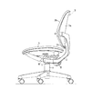
図において、1はオフィス用回転椅子などの座板、2はこの座板1の後方から立ち上げられた背もたれの支持アームである。支持アーム2は、ここでは下部側が座板1の下側に向けて曲げられその先端部が椅子のベース部材Bに固定、或は、回動可能に取付けられている。支持アーム2がベース部材Bに回動可能に取付けられる場合、支持アーム2は、座板1に対し前,後に傾動可能で、前傾する方向にバネなどにより付勢されている。なお、Tは支持アーム2をベース部材Bに回動可能に取付けるときの枢着軸である。
In the figure, reference numeral 1 denotes a seat plate such as an office swivel chair, and 2 denotes a support arm for a backrest raised from the rear of the seat plate 1. Here, the lower side of the
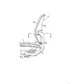
3は背もたれ支持アーム2の前面に設けられた背もたれで、ここでは背面側のアウターシェル3aと前面側の背当て部材3bを重ね合わせて形成されている。背もたれ3は、その下部に設けた枢着部3cが背もたれ支持アーム2の立ち上がり部に形成されている軸支部2aに水平な取付軸mにより取付けられ、この取付軸mを中心に背もたれ3が前,後に傾動可能である。即ち、背もたれ支持アーム2が後傾したときでも、背もたれ3は枢着部3cを中心にこの支持アーム2の前面側において前,後に傾動する自由度を保持している。
背もたれ支持アーム2の軸支部2aに軸mにより枢支された上記背もたれ3は、上方において背面側の左,右がそれぞれ前後揺動可能に支持される。即ち、背もたれ支持アーム2の上で背もたれ3を前後揺動可能に支持する構造は、ここでは支持アーム2の上部側の左,右両端部と背シェル3aの左,右両側との間に弾性部材4,4を介在させて行っている。弾性部材4としては、図示した例では短柱状乃至は鼓状に形成したゴムを使用しているが、ゴム以外にバネ、例えば、板バネやコイルスプリングなども使用することができる。
The
次に、図2〜図5により、背もたれ3の支持構造についてより詳細に説明する。背もたれ支持アーム2の上部側が左右に拡開し、その左,右両端部側が前方に弯曲していて、弯曲部の前端面がそれぞれ背もたれ3の背シェル3aの左,右に対向している。当該前端面には、その略中央部から前方に向け支持杆2b,2bが突設形成され、それぞれの支持杆2b,2bの先端側には、先端面に平行な横向きの係合溝2c,2cが形成されている。なお、2dは支持杆2bの先端面の略中央部に設けたネジ孔である。
Next, the support structure of the
上記の支持杆2b,2bは、前面側にブロック状の弾性部材4,4を支持させた状態でアウターシェル3aの左,右に設けられた嵌合孔5,5に遊挿される。嵌合孔5,5は、支持杆2b,2bが上,下に変位し得るように縦長に形成されていると共に、側面側がテーパ面5aに形成されている。6は前記弾性部材4を支持して、嵌合孔5に遊挿された支持杆2bの先端部に取付けられる係止部材で、後面側が嵌合孔5のテーパ面5aに支持される弯曲面6aに形成されている。6bは前記係止部材6の後面側において弯曲面6aの前方に横向きに形成した係合片で、この係合片6bは、係止部材6を支持杆2bの先端部に取付けるとき、当該支持杆2bの先端側に形成した係合溝2cに嵌合される。
The
ここで図4,図5により、背もたれ3と支持アーム2の取付態様について詳述すると、まず、支持アーム2の上部側左,右の支持杆2b,2bに弾性部材4を嵌めて保持させ(図4,図5では図示せず)、この状態で背もたれ3のアウターシェル3aに形成した左右の嵌合孔5,5を嵌合させると共に、アウターシェル3aの前面側に突出した支持杆2b,2bのそれぞれの先端部に、係止部材6,6をその係合片6b,6bを当該支持杆2b,2bの先端側の係合溝2c,2cに嵌合させ、係止部材6の略中央部に形成されている穴6c,6cに前面側からタッピングビス6d,6dを入れ、支持杆2b,2bの先端面のネジ孔2d,2dに螺入して固定する。なお、着座者が背もたれ3に寄りかかったとき、アウターシェル3aが弯曲するなどして支持杆2b,2bに対して相対的に変位しても、嵌合孔5,5のテーパ面5a,5aは係止部材6の後面側の弯曲面6aに対し摺動を許容しているので、係止部材6には余計な負荷がかからず、損壊することはない。
4 and 5, the mounting manner of the
なお、背もたれ3はその背面側の左,右において前,後に揺動可能に支持されるのであれば、上記以外の支持構造にしてもよい。また、背もたれ3は、その下部の略央部に位置する軸支点と、該支点より上方の背面側における左,右の2点の支持により、3つの支持点が略逆三角形状をなすように形成するのが、着座者の背中を均等に支持すると共に、着座者の右又は左に偏った後傾を支持する上で好ましい。
The
本発明の一例の背もたれ支持機構の構成は以上の通りであるので、次にその動作内容について説明する。着座者の姿勢変化により背もたれ3はその支持アーム2と共に後方に傾動する。背もたれ3が後方に傾動したとき、背もたれ3の上部側は背中によって大きな荷重を受けるが、この荷重は背もたれ支持アーム2による背もたれ3の前方への付勢力と均衡を保っている。しかし、着座者の腰部を中心に傾動するその着座者の背中と椅子の座板1の下側に傾動中心が設けられた背もたれ支持アーム2とでは、それぞれの傾動の中心が異なっているので、背もたれ3が後方に大きく傾動するとき、当該背もたれ3は、支持アーム2の後傾による後方回動とその背もたれ3の支持アーム2上での軸mを中心とする後方回動との複合後傾となり、着座者の背中の後傾する動きによく追従した動作をする。
The configuration of the back support mechanism according to the example of the present invention is as described above. The
また、背もたれ3の後傾において、着座者の姿勢が右又は左に傾いたり、捩れたりしたとき、背もたれ3はその傾いたり捩れたりした側に大きな偏荷重を受けるが、本発明背もたれ支持機構では、偏荷重を受けた側に傾動して背中の動きによく追従する。更に、本発明背もたれ支持機構では、背もたれ3が後方に大きく傾動する場合、背もたれ3はその下部が軸mにより支持アーム2に枢支されているので、背もたれ3の上部側が支持アーム2に対し上下方向に変位するが、背もたれ支持アーム2の支持杆2b,2bがアウターシェル3aの左,右に設けられた縦長の嵌合孔5,5に遊挿されこの嵌合孔5,5内において上,下に変位することにより対応できる。
In addition, when the seated person is tilted to the right or left or twisted while the
以上に説明した本発明の背もたれ支持機構を具備するオフィス用の回転椅子の一例を図6に示す。図6に示した椅子では、支持アーム2の下部側が、座板1の下側に向けて曲げられその先端部が脚の支柱7の上部に設けたベース部材Bに枢着軸Tにより回動可能に取り付けられている。8は座板1に対し前後揺動可能で、内部のバネ(図示せず)により前方に付勢されている支持アーム2の前記バネの強弱を調節する操作部である。
An example of an office swivel chair provided with the back support mechanism of the present invention described above is shown in FIG. In the chair shown in FIG. 6, the lower side of the
本発明は以上の通りであって、本発明背もたれの支持機構によれば、着座者の後傾を、支持アームの後傾とこのアームの立ち上がり部に設けた軸を中心に後傾する背もたれとで受けるようにしたので、着座者の後傾動作に背もたれの動作をよく追従させることができる。 The present invention is as described above, and according to the support mechanism of the backrest of the present invention, the backrest of the seated person can be tilted backward with the rearward tilt of the support arm and the axis provided at the rising portion of the arm. Therefore, the movement of the backrest can be made to follow the backward tilting movement of the seated person well.
また、本発明背もたれの支持機構によれば、着座者の姿勢がその背中部分が後傾し乍ら左又は右に傾いたときや捩れたときでも、背もたれの上部側左右と支持アームの上部側左右に介在させた弾性部材の作用により、その傾き等に正確に追従してその傾き等による偏荷重を好適に吸収し得るので、着座者に違和感を与えることはない。 Further, according to the backrest support mechanism of the present invention, even when the posture of the seated person is tilted to the left or right while the back portion is tilted backward or twisted, the upper side of the backrest and the upper side of the support arm By the action of the elastic members interposed on the left and right sides, it is possible to accurately follow the inclination and absorb the uneven load due to the inclination and the like, so that the seated person does not feel uncomfortable.
更に、本発明背もたれの支持機構は、上記のような機能を有しながら構造が簡単で背もたれも薄手に形成することができるので、コストを低減化できる上に、デザイン的にも最近の椅子に適合するものである。 Furthermore, the support mechanism for the backrest of the present invention has the above-described functions, and has a simple structure and a thin backrest. Therefore, the cost can be reduced and the design can be applied to a modern chair. It is suitable.
1 座板
2 背もたれ支持アーム
3 背もたれ
4 弾性部材
5 嵌合孔
6 係合部材
7 脚の支柱
8 操作部
B ベース部材
DESCRIPTION OF SYMBOLS 1
Claims (1)
Priority Applications (1)
| Application Number | Priority Date | Filing Date | Title |
|---|---|---|---|
| JP2012257013A JP5566438B2 (en) | 2012-11-26 | 2012-11-26 | Chair back support mechanism |
Applications Claiming Priority (1)
| Application Number | Priority Date | Filing Date | Title |
|---|---|---|---|
| JP2012257013A JP5566438B2 (en) | 2012-11-26 | 2012-11-26 | Chair back support mechanism |
Related Parent Applications (1)
| Application Number | Title | Priority Date | Filing Date |
|---|---|---|---|
| JP2010181540A Division JP5279773B2 (en) | 2010-08-16 | 2010-08-16 | Chair back support mechanism |
Publications (3)
| Publication Number | Publication Date |
|---|---|
| JP2013039434A JP2013039434A (en) | 2013-02-28 |
| JP2013039434A5 JP2013039434A5 (en) | 2013-08-22 |
| JP5566438B2 true JP5566438B2 (en) | 2014-08-06 |
Family
ID=47888365
Family Applications (1)
| Application Number | Title | Priority Date | Filing Date |
|---|---|---|---|
| JP2012257013A Expired - Fee Related JP5566438B2 (en) | 2012-11-26 | 2012-11-26 | Chair back support mechanism |
Country Status (1)
| Country | Link |
|---|---|
| JP (1) | JP5566438B2 (en) |
Family Cites Families (8)
| Publication number | Priority date | Publication date | Assignee | Title |
|---|---|---|---|---|
| JPS59114059U (en) * | 1983-01-24 | 1984-08-01 | 株式会社岡村製作所 | chair back support device |
| JPS6054449U (en) * | 1983-09-22 | 1985-04-17 | 株式会社岡村製作所 | Backrest attachment device for chairs |
| JPH01114853U (en) * | 1988-01-28 | 1989-08-02 | ||
| US5249839A (en) * | 1991-11-12 | 1993-10-05 | Steelcase Inc. | Split back chair |
| JPH0580346U (en) * | 1992-04-07 | 1993-11-02 | 横浜ゴム株式会社 | Chair |
| JP3103304B2 (en) * | 1995-11-06 | 2000-10-30 | アイコ株式会社 | Chair tilting method and chair with tiltable back |
| JP3884186B2 (en) * | 1998-07-09 | 2007-02-21 | 株式会社岡村製作所 | Chair |
| WO2000022959A1 (en) * | 1998-10-20 | 2000-04-27 | Protoned B.V. | Chair mechanism |
-
2012
- 2012-11-26 JP JP2012257013A patent/JP5566438B2/en not_active Expired - Fee Related
Also Published As
| Publication number | Publication date |
|---|---|
| JP2013039434A (en) | 2013-02-28 |
Similar Documents
| Publication | Publication Date | Title |
|---|---|---|
| JP4627931B2 (en) | Chair back support mechanism | |
| JP2015177979A (en) | chair | |
| JP3330145B2 (en) | Interlocking support mechanism for chair back and seat | |
| US20150245713A1 (en) | Chair, in particular office chair | |
| WO2002032265A1 (en) | Chair | |
| JP2007268118A (en) | Stool rockable in seat part | |
| JP5279773B2 (en) | Chair back support mechanism | |
| JP4792234B2 (en) | Chair | |
| JP4950486B2 (en) | Chair | |
| JP2013000446A (en) | Chair | |
| JP4792235B2 (en) | Chair | |
| JP5566438B2 (en) | Chair back support mechanism | |
| KR100908737B1 (en) | A chair | |
| JP5567402B2 (en) | Chair | |
| JP2013000445A (en) | Chair | |
| KR101378062B1 (en) | Chair | |
| JP4792233B2 (en) | Chair | |
| EP3700392A1 (en) | Articulation system for chairs | |
| JP5616134B2 (en) | Chair | |
| JP2012223284A (en) | Chair | |
| GB2565537B (en) | Office chair | |
| JP5078311B2 (en) | Chair | |
| JP2006110068A (en) | Table provided with auxiliary top plate | |
| JP5635362B2 (en) | Chair with armrests | |
| KR100908736B1 (en) | Tilting apparatus and chair having it |
Legal Events
| Date | Code | Title | Description |
|---|---|---|---|
| A621 | Written request for application examination |
Free format text: JAPANESE INTERMEDIATE CODE: A621 Effective date: 20121126 |
|
| A521 | Request for written amendment filed |
Free format text: JAPANESE INTERMEDIATE CODE: A523 Effective date: 20130708 |
|
| A521 | Request for written amendment filed |
Free format text: JAPANESE INTERMEDIATE CODE: A523 Effective date: 20131031 |
|
| RD04 | Notification of resignation of power of attorney |
Free format text: JAPANESE INTERMEDIATE CODE: A7424 Effective date: 20140106 |
|
| A131 | Notification of reasons for refusal |
Free format text: JAPANESE INTERMEDIATE CODE: A131 Effective date: 20140218 |
|
| A521 | Request for written amendment filed |
Free format text: JAPANESE INTERMEDIATE CODE: A523 Effective date: 20140418 |
|
| TRDD | Decision of grant or rejection written | ||
| A01 | Written decision to grant a patent or to grant a registration (utility model) |
Free format text: JAPANESE INTERMEDIATE CODE: A01 Effective date: 20140617 |
|
| A61 | First payment of annual fees (during grant procedure) |
Free format text: JAPANESE INTERMEDIATE CODE: A61 Effective date: 20140617 |
|
| R150 | Certificate of patent or registration of utility model |
Ref document number: 5566438 Country of ref document: JP Free format text: JAPANESE INTERMEDIATE CODE: R150 |
|
| S531 | Written request for registration of change of domicile |
Free format text: JAPANESE INTERMEDIATE CODE: R313531 |
|
| R350 | Written notification of registration of transfer |
Free format text: JAPANESE INTERMEDIATE CODE: R350 |
|
| LAPS | Cancellation because of no payment of annual fees |