JP2010066653A - 画像形成装置 - Google Patents
画像形成装置 Download PDFInfo
- Publication number
- JP2010066653A JP2010066653A JP2008234520A JP2008234520A JP2010066653A JP 2010066653 A JP2010066653 A JP 2010066653A JP 2008234520 A JP2008234520 A JP 2008234520A JP 2008234520 A JP2008234520 A JP 2008234520A JP 2010066653 A JP2010066653 A JP 2010066653A
- Authority
- JP
- Japan
- Prior art keywords
- filter
- image forming
- forming apparatus
- filter sheet
- suction
- Prior art date
- Legal status (The legal status is an assumption and is not a legal conclusion. Google has not performed a legal analysis and makes no representation as to the accuracy of the status listed.)
- Granted
Links
- 238000004140 cleaning Methods 0.000 claims abstract description 63
- 239000000428 dust Substances 0.000 claims abstract description 47
- 238000011144 upstream manufacturing Methods 0.000 claims abstract description 9
- 230000007246 mechanism Effects 0.000 claims description 11
- 239000000835 fiber Substances 0.000 claims description 8
- 238000010030 laminating Methods 0.000 claims description 2
- 238000011084 recovery Methods 0.000 claims description 2
- 238000012423 maintenance Methods 0.000 abstract description 5
- 230000006866 deterioration Effects 0.000 abstract 1
- 239000010410 layer Substances 0.000 description 18
- 238000012546 transfer Methods 0.000 description 14
- CBENFWSGALASAD-UHFFFAOYSA-N Ozone Chemical compound [O-][O+]=O CBENFWSGALASAD-UHFFFAOYSA-N 0.000 description 12
- 108091008695 photoreceptors Proteins 0.000 description 10
- 230000000694 effects Effects 0.000 description 5
- 230000006870 function Effects 0.000 description 5
- 230000009471 action Effects 0.000 description 3
- 230000005540 biological transmission Effects 0.000 description 3
- 238000000034 method Methods 0.000 description 3
- 230000015572 biosynthetic process Effects 0.000 description 2
- 230000001186 cumulative effect Effects 0.000 description 2
- 238000010586 diagram Methods 0.000 description 2
- 230000033001 locomotion Effects 0.000 description 2
- 239000002184 metal Substances 0.000 description 2
- 230000004048 modification Effects 0.000 description 2
- 238000012986 modification Methods 0.000 description 2
- 238000012545 processing Methods 0.000 description 2
- 229920003002 synthetic resin Polymers 0.000 description 2
- 239000000057 synthetic resin Substances 0.000 description 2
- 238000009825 accumulation Methods 0.000 description 1
- 230000002411 adverse Effects 0.000 description 1
- 238000003705 background correction Methods 0.000 description 1
- 238000006243 chemical reaction Methods 0.000 description 1
- 230000006835 compression Effects 0.000 description 1
- 238000007906 compression Methods 0.000 description 1
- 239000000470 constituent Substances 0.000 description 1
- 239000004745 nonwoven fabric Substances 0.000 description 1
- 239000011120 plywood Substances 0.000 description 1
- 230000008569 process Effects 0.000 description 1
- 230000009467 reduction Effects 0.000 description 1
- 238000007790 scraping Methods 0.000 description 1
- 239000002356 single layer Substances 0.000 description 1
- 238000009423 ventilation Methods 0.000 description 1
- 239000002759 woven fabric Substances 0.000 description 1
Images


Landscapes
- Dry Development In Electrophotography (AREA)
- Control Or Security For Electrophotography (AREA)
Abstract
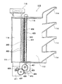
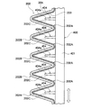
【解決手段】飛散トナーを吸い込む吸引ダクトの下流側に、吸引ファン115を備えた集塵装置110が配置され、吸引ファン115の上流側に蛇腹状に折り曲げられて複数の折り目を有するフィルタシート202が配置され、このフィルタシート202の折り目同士の間の溝部内に清掃板404に形成された複数の突出片404aが挿入され、この清掃板404を備えるフィルタ清掃枠体400を上下方向に往復駆動させるようにした。
【選択図】図6
Description
(その他の実施の形態)
以上、本発明の実施の形態について説明したが、この開示の一部をなす論述及び図面はこの発明を限定するものであると理解すべきではない。この開示から当業者には様々な代替実施の形態、実施例及び運用技術が明らかとなろう。
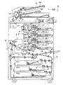
9…吸引ダクト
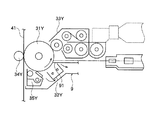
31M,31Y,31C,31K…感光体
33Y,33M,33C,33K…現像部
43…ベルトクリーニング部
91,92…開口部
110…集塵装置
111…筐体
112…吸入室
113…排気室
114…導入ダクト
115…吸引ファン
200…集塵フィルタ
202…フィルタシート
202A,202B…折り目
202C…溝部
203…ネット層
204…繊維層
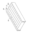
400…フィルタ清掃枠体
403…カムスライド部
404,404A,404B…清掃板
404a…突出片
406,407,408…伝達ギア
409…回収容器
410…偏心カム
411…モータ
Claims (7)
- 感光体上の潜像をトナーで現像する現像部と、
少なくとも前記現像部の近傍に発生した飛散トナーを吸引する吸引ダクトと、
前記吸引ダクトの下流側に配置されて前記吸引ダクト内の空気を吸引する吸引ファンと、
前記吸引ファンの上流側に配置され、前記吸引ダクト内を搬送される飛散トナーを捕捉する、蛇腹状に折り曲げられて複数の折り目を有するフィルタシートと、
前記フィルタシートの上流側に配置され、前記フィルタシートの前記折り目に沿って配置され、且つ前記折り目同士の間の溝部内に挿入される複数の突出片が互いに隙間を隔てて一体的に形成された清掃板を、複数枚備えたフィルタ清掃枠体と、
前記フィルタ清掃枠体又は前記フィルタシートを、前記折り目と直交する方向に往復駆動させる往復駆動機構と、
を備えることを特徴とする画像形成装置。 - 前記フィルタシートは、ネット層と繊維層とが積層されてなり、前記ネット層が上流側を向くように配置され、
前記突出片は前記ネット層側の前記溝部内に挿入されていることを特徴とする請求項1に記載の画像形成装置。 - 前記フィルタシートは、前記折り目が水平方向となるように配置され、
前記往復駆動機構は、前記フィルタ清掃枠体又は前記フィルタシートを上下方向に往復駆動させることを特徴とする請求項1又は請求項2に記載の画像形成装置。 - 前記フィルタシートの下方に、落下するトナーを収納する回収容器が配置されていることを特徴とする請求項1乃至請求項3のいずれか一項に記載の画像形成装置。
- 前記往復駆動機構は、前記吸引ファンを停止させた状態で駆動されることを特徴とする請求項1乃至請求項4のいずれか一項に記載の画像形成装置。
- 前記吸引ダクトの下流側は集塵装置に接続され、
前記集塵装置は、前記吸引ダクトから空気が流れ込む吸入室と、前記フィルタ清掃枠体及び前記フィルタシートとで前記吸入室と空間が通気可能に隔てられた排気室と、前記排気室側に設けられた前記吸引ファンと、を備えることを特徴とする請求項1乃至請求項5のいずれか一項に記載の画像形成装置。 - 前記フィルタシートは、取り付け、取り外しが可能であることを特徴とする請求項1乃至請求項6のいずれか一項に記載の画像形成装置。
Priority Applications (1)
| Application Number | Priority Date | Filing Date | Title |
|---|---|---|---|
| JP2008234520A JP5071319B2 (ja) | 2008-09-12 | 2008-09-12 | 画像形成装置 |
Applications Claiming Priority (1)
| Application Number | Priority Date | Filing Date | Title |
|---|---|---|---|
| JP2008234520A JP5071319B2 (ja) | 2008-09-12 | 2008-09-12 | 画像形成装置 |
Publications (2)
| Publication Number | Publication Date |
|---|---|
| JP2010066653A true JP2010066653A (ja) | 2010-03-25 |
| JP5071319B2 JP5071319B2 (ja) | 2012-11-14 |
Family
ID=42192274
Family Applications (1)
| Application Number | Title | Priority Date | Filing Date |
|---|---|---|---|
| JP2008234520A Expired - Fee Related JP5071319B2 (ja) | 2008-09-12 | 2008-09-12 | 画像形成装置 |
Country Status (1)
| Country | Link |
|---|---|
| JP (1) | JP5071319B2 (ja) |
Citations (3)
| Publication number | Priority date | Publication date | Assignee | Title |
|---|---|---|---|---|
| JP2006281090A (ja) * | 2005-03-31 | 2006-10-19 | Amano Corp | 集塵装置 |
| JP2007298782A (ja) * | 2006-05-01 | 2007-11-15 | Konica Minolta Business Technologies Inc | 画像形成装置 |
| JP2008022933A (ja) * | 2006-07-19 | 2008-02-07 | Matsushita Electric Ind Co Ltd | フィルターユニット及びそのフィルターユニットを用いた電気掃除機 |
-
2008
- 2008-09-12 JP JP2008234520A patent/JP5071319B2/ja not_active Expired - Fee Related
Patent Citations (3)
| Publication number | Priority date | Publication date | Assignee | Title |
|---|---|---|---|---|
| JP2006281090A (ja) * | 2005-03-31 | 2006-10-19 | Amano Corp | 集塵装置 |
| JP2007298782A (ja) * | 2006-05-01 | 2007-11-15 | Konica Minolta Business Technologies Inc | 画像形成装置 |
| JP2008022933A (ja) * | 2006-07-19 | 2008-02-07 | Matsushita Electric Ind Co Ltd | フィルターユニット及びそのフィルターユニットを用いた電気掃除機 |
Also Published As
| Publication number | Publication date |
|---|---|
| JP5071319B2 (ja) | 2012-11-14 |
Similar Documents
| Publication | Publication Date | Title |
|---|---|---|
| CN104076669B (zh) | 调色剂回收装置、及具备该调色剂回收装置的图像形成装置 | |
| JP4070939B2 (ja) | 画像形成装置 | |
| CN1963693B (zh) | 图像形成装置 | |
| EP3396463B1 (en) | Optical scanning device | |
| CN102467062B (zh) | 显影剂收集装置和图像形成装置 | |
| JP2007033945A (ja) | 画像形成のための装置および画像形成ユニット | |
| JP5071319B2 (ja) | 画像形成装置 | |
| JP5372689B2 (ja) | 画像形成装置 | |
| JP4086175B2 (ja) | 画像形成装置 | |
| CN110083038B (zh) | 图像形成装置 | |
| US8787787B2 (en) | Image forming apparatus discharging ozone from charger | |
| JP2002277036A (ja) | 送風装置 | |
| CN110095967B (zh) | 图像形成装置 | |
| CN106168745B (zh) | 废色调剂容器以及图像形成设备 | |
| JP5836305B2 (ja) | トナー回収装置、およびこれを備えた画像形成装置 | |
| JP2016051053A (ja) | 気体の清浄化装置および画像形成装置 | |
| JP5145651B2 (ja) | 光走査装置及び画像形成装置 | |
| JP5723816B2 (ja) | 画像読取装置及びこれを備えた画像形成装置 | |
| JP6088612B2 (ja) | 画像形成装置 | |
| JP2009260700A (ja) | 画像読取装置 | |
| JP2008003336A (ja) | 画像形成装置 | |
| JP2015138247A (ja) | 画像形成装置 | |
| JP2007290318A (ja) | 光走査装置及び画像形成装置 | |
| JP2006084614A (ja) | プロセスキット及び画像形成装置 |
Legal Events
| Date | Code | Title | Description |
|---|---|---|---|
| A621 | Written request for application examination |
Free format text: JAPANESE INTERMEDIATE CODE: A621 Effective date: 20110316 |
|
| TRDD | Decision of grant or rejection written | ||
| A01 | Written decision to grant a patent or to grant a registration (utility model) |
Free format text: JAPANESE INTERMEDIATE CODE: A01 Effective date: 20120724 |
|
| A01 | Written decision to grant a patent or to grant a registration (utility model) |
Free format text: JAPANESE INTERMEDIATE CODE: A01 |
|
| A977 | Report on retrieval |
Free format text: JAPANESE INTERMEDIATE CODE: A971007 Effective date: 20120725 |
|
| A61 | First payment of annual fees (during grant procedure) |
Free format text: JAPANESE INTERMEDIATE CODE: A61 Effective date: 20120806 |
|
| R150 | Certificate of patent or registration of utility model |
Ref document number: 5071319 Country of ref document: JP Free format text: JAPANESE INTERMEDIATE CODE: R150 Free format text: JAPANESE INTERMEDIATE CODE: R150 |
|
| FPAY | Renewal fee payment (event date is renewal date of database) |
Free format text: PAYMENT UNTIL: 20150831 Year of fee payment: 3 |
|
| S111 | Request for change of ownership or part of ownership |
Free format text: JAPANESE INTERMEDIATE CODE: R313111 |
|
| R350 | Written notification of registration of transfer |
Free format text: JAPANESE INTERMEDIATE CODE: R350 |
|
| LAPS | Cancellation because of no payment of annual fees |