JP2010065655A - 内燃機関のカムホルダ構造 - Google Patents
内燃機関のカムホルダ構造 Download PDFInfo
- Publication number
- JP2010065655A JP2010065655A JP2008235087A JP2008235087A JP2010065655A JP 2010065655 A JP2010065655 A JP 2010065655A JP 2008235087 A JP2008235087 A JP 2008235087A JP 2008235087 A JP2008235087 A JP 2008235087A JP 2010065655 A JP2010065655 A JP 2010065655A
- Authority
- JP
- Japan
- Prior art keywords
- cam
- internal combustion
- combustion engine
- cam holder
- cap
- Prior art date
- Legal status (The legal status is an assumption and is not a legal conclusion. Google has not performed a legal analysis and makes no representation as to the accuracy of the status listed.)
- Granted
Links
Images

Classifications
-
- F—MECHANICAL ENGINEERING; LIGHTING; HEATING; WEAPONS; BLASTING
- F01—MACHINES OR ENGINES IN GENERAL; ENGINE PLANTS IN GENERAL; STEAM ENGINES
- F01L—CYCLICALLY OPERATING VALVES FOR MACHINES OR ENGINES
- F01L1/00—Valve-gear or valve arrangements, e.g. lift-valve gear
- F01L1/02—Valve drive
- F01L1/04—Valve drive by means of cams, camshafts, cam discs, eccentrics or the like
- F01L1/047—Camshafts
- F01L1/053—Camshafts overhead type
Landscapes
- Valve-Gear Or Valve Arrangements (AREA)
- Lubrication Of Internal Combustion Engines (AREA)
Abstract
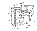
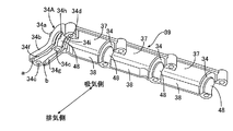
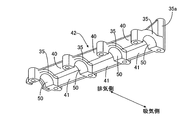
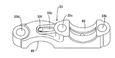
【解決手段】 内燃機関のタイミングトレーン側のカムホルダを、カムホルダ本体36と、カムホルダ本体36の上面に結合される吸気側カムキャップ34Aおよび排気側カムキャップ35とで構成し、そのうちの吸気側カムキャップ34Aに吸気カムシャフトの軸受け部48から排気側に向かって延びる延出部34bを設けたので、タイミングトレーンからの荷重が加わる吸気カムシャフトの端部を、延出部34bによってカムホルダ本体36の合わせ面との結合面積が増加した吸気側カムキャップ34Aで強固に支持することができるだけでなく、タイミングトレーンを介して動弁室内に侵入しようとする高温のオイルミストを、吸気側カムキャップ34Aの延出部34bによって遮ることができる。
【選択図】 図7
Description
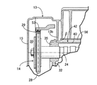
13 ヘッドカバー
13a 隔壁
13b 隔壁
14 タイミングトレーン
18 吸気カムシャフト(カムシャフト)
24 排気カムシャフト(カムシャフト)
29 タイミングチェーン
34 吸気側カムキャップ
34A 端部カムキャップ(吸気側カムキャップ)
34b 延出部
34c ボルト孔
34e ボルト孔(第2ボルト孔)
34f 進角用油路(油路)
34g 進角用油路(油路)
35 排気側カムキャップ
36 カムホルダ本体
45A ボルト
48 軸受け部
a オイルの流入部
b オイルの流入部
D 油路の深さ
L 気筒列線
W 油路の幅
Claims (8)
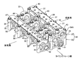
- シリンダヘッド(12)の上面に設けられたカムホルダ本体(36)と、前記カムホルダ本体(36)の上側の合わせ面に結合されて該カムホルダ本体(36)との間にカムシャフト(18,24)を支持するカムキャップ(34,34A,35)とからなるカムホルダを、気筒列線(L)に沿って複数配置した内燃機関のカムホルダ構造において、
前記カムキャップは、吸気側カムキャップ(34,34A)と排気側カムキャップ(35)とが別個に形成され、
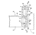
複数の吸気側カムキャップ(34,34A)および複数の排気側カムキャップ(35)の一方のうち、タイミングトレーン(14)側の端部に位置する端部カムキャップ(34A)は、それが結合されるカムホルダ本体(36)との間に形成される軸受け部(48)から前記合わせ面に沿って吸気側および排気側の他方に向かって延びる延出部(34b)を備えることを特徴とする内燃機関のカムホルダ構造。 - 前記タイミングトレーン(14)はタイミングチェーン(29)を含むことを特徴とする、請求項1に記載の内燃機関のカムホルダ構造。
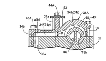
- 前記端部カムキャップ(34A)の前記カムホルダ本体(36)との合わせ面に、前記延出部(34b)から前記軸受け部(48)に給油する油路(34f,34g)が形成されることを特徴とする、請求項1または請求項2に記載の内燃機関のカムホルダ構造。
- 前記端部カムキャップ(34A)の前記延出部(34b)の先端に、前記カムシャフト(18)を前記カムホルダ本体(36)に締結するボルト(45A)が貫通するボルト孔(34c)が形成されており、前記ボルト孔(34c)の近傍に前記油路(34f,34g)へのオイルの流入部(a,b)が形成されることを特徴とする、請求項3に記載の内燃機関のカムホルダ構造。
- 前記端部カムキャップ(34A)の前記延出部(34b)と前記軸受け部(48)との間に第2ボルト孔(34e)が形成されており、前記第2ボルト孔(34e)の近傍における前記油路(34f,34g)は、その他の部分における油路(34f,34g)に比べて幅(W)が小さく深さ(D)が大きく形成されることを特徴とする、請求項4に記載の内燃機関のカムホルダ構造。
- 前記油路は、前記ボルト孔(34c)および前記第2ボルト孔(34e)を挟んで並行する2本の油路(34f,34g)からなることを特徴とする、請求項5に記載の内燃機関のカムホルダ構造。
- 前記シリンダヘッド(12)の上面に結合されるヘッドカバー(13)は、前記端部カムキャップ(34A)の上面に向けて下向きに突出する隔壁(13a,13b)を備えることを特徴とする、請求項1〜請求項6の何れか1項に記載の内燃機関のカムホルダ構造。
- 前記複数の吸気側カムキャップ(34,34A)および前記複数の排気側カムキャップ(35)は、上面および気筒列線(L)側の側面が相互に連結され、反気筒列線(L)側の側面が開放することを特徴とする、請求項1〜請求項7の何れか1項に記載の内燃機関のカムホルダ構造。
Priority Applications (1)
| Application Number | Priority Date | Filing Date | Title |
|---|---|---|---|
| JP2008235087A JP5142900B2 (ja) | 2008-09-12 | 2008-09-12 | 内燃機関のカムホルダ構造 |
Applications Claiming Priority (1)
| Application Number | Priority Date | Filing Date | Title |
|---|---|---|---|
| JP2008235087A JP5142900B2 (ja) | 2008-09-12 | 2008-09-12 | 内燃機関のカムホルダ構造 |
Publications (2)
| Publication Number | Publication Date |
|---|---|
| JP2010065655A true JP2010065655A (ja) | 2010-03-25 |
| JP5142900B2 JP5142900B2 (ja) | 2013-02-13 |
Family
ID=42191438
Family Applications (1)
| Application Number | Title | Priority Date | Filing Date |
|---|---|---|---|
| JP2008235087A Expired - Fee Related JP5142900B2 (ja) | 2008-09-12 | 2008-09-12 | 内燃機関のカムホルダ構造 |
Country Status (1)
| Country | Link |
|---|---|
| JP (1) | JP5142900B2 (ja) |
Cited By (2)
| Publication number | Priority date | Publication date | Assignee | Title |
|---|---|---|---|---|
| JP2013144953A (ja) * | 2012-01-16 | 2013-07-25 | Suzuki Motor Corp | カムシャフトのスラスト軸受潤滑構造 |
| JP2021011861A (ja) * | 2019-07-09 | 2021-02-04 | トヨタ自動車株式会社 | 内燃機関 |
Citations (6)
| Publication number | Priority date | Publication date | Assignee | Title |
|---|---|---|---|---|
| JPH06101423A (ja) * | 1992-09-21 | 1994-04-12 | Nissan Motor Co Ltd | エンジンのカムシャフト支持構造 |
| JPH06200712A (ja) * | 1992-12-28 | 1994-07-19 | Suzuki Motor Corp | エンジンの動弁装置 |
| JP2002276308A (ja) * | 2001-03-21 | 2002-09-25 | Yamaha Motor Co Ltd | 4サイクルエンジンのカム軸支持構造 |
| JP2002285817A (ja) * | 2001-03-26 | 2002-10-03 | Aichi Mach Ind Co Ltd | オイルセパレーターチャンバー |
| JP2005194911A (ja) * | 2004-01-05 | 2005-07-21 | Honda Motor Co Ltd | 動弁装置の潤滑油供給構造 |
| JP2007205299A (ja) * | 2006-02-03 | 2007-08-16 | Toyota Motor Corp | 内燃機関のシリンダヘッド |
-
2008
- 2008-09-12 JP JP2008235087A patent/JP5142900B2/ja not_active Expired - Fee Related
Patent Citations (6)
| Publication number | Priority date | Publication date | Assignee | Title |
|---|---|---|---|---|
| JPH06101423A (ja) * | 1992-09-21 | 1994-04-12 | Nissan Motor Co Ltd | エンジンのカムシャフト支持構造 |
| JPH06200712A (ja) * | 1992-12-28 | 1994-07-19 | Suzuki Motor Corp | エンジンの動弁装置 |
| JP2002276308A (ja) * | 2001-03-21 | 2002-09-25 | Yamaha Motor Co Ltd | 4サイクルエンジンのカム軸支持構造 |
| JP2002285817A (ja) * | 2001-03-26 | 2002-10-03 | Aichi Mach Ind Co Ltd | オイルセパレーターチャンバー |
| JP2005194911A (ja) * | 2004-01-05 | 2005-07-21 | Honda Motor Co Ltd | 動弁装置の潤滑油供給構造 |
| JP2007205299A (ja) * | 2006-02-03 | 2007-08-16 | Toyota Motor Corp | 内燃機関のシリンダヘッド |
Cited By (3)
| Publication number | Priority date | Publication date | Assignee | Title |
|---|---|---|---|---|
| JP2013144953A (ja) * | 2012-01-16 | 2013-07-25 | Suzuki Motor Corp | カムシャフトのスラスト軸受潤滑構造 |
| JP2021011861A (ja) * | 2019-07-09 | 2021-02-04 | トヨタ自動車株式会社 | 内燃機関 |
| JP7306116B2 (ja) | 2019-07-09 | 2023-07-11 | トヨタ自動車株式会社 | 内燃機関 |
Also Published As
| Publication number | Publication date |
|---|---|
| JP5142900B2 (ja) | 2013-02-13 |
Similar Documents
| Publication | Publication Date | Title |
|---|---|---|
| JP4386112B2 (ja) | エンジン | |
| JP5088344B2 (ja) | 多気筒エンジンの集合排気ポート一体型シリンダヘッドのオイル戻し通路構造 | |
| JP4978383B2 (ja) | 潤滑装置 | |
| US8820277B2 (en) | Engine assembly including cylinder head oil gallery | |
| JP2623856B2 (ja) | 内燃機関のシリンダヘッド | |
| JP5662965B2 (ja) | エンジンの潤滑油供給機構 | |
| JPH0874541A (ja) | 4サイクルエンジン | |
| EP2881556B1 (en) | Engine | |
| JP6713710B2 (ja) | スラント型内燃機関 | |
| JP4657134B2 (ja) | 4サイクル空油冷エンジンにおけるオイル通路構造 | |
| JP5142900B2 (ja) | 内燃機関のカムホルダ構造 | |
| JP5751392B1 (ja) | エンジンの動弁機構 | |
| JP2016050501A (ja) | エンジンのオイル供給装置 | |
| EP1403497B1 (en) | Camshaft bearing structure for over-head camshaft type internal combustion engine | |
| JP3142609B2 (ja) | エンジンのシリンダヘッド構造 | |
| JP6092813B2 (ja) | 内燃機関の軸受の潤滑油供給構造 | |
| JP2013113158A (ja) | 内燃機関のヘッドカバー構造 | |
| JP4326267B2 (ja) | 多気筒内燃機関の動弁装置 | |
| JP3329415B2 (ja) | 4サイクルエンジン | |
| JP3821342B2 (ja) | 内燃機関のオイル通路構造 | |
| JP4176407B2 (ja) | エンジン | |
| JPH0932561A (ja) | 4サイクルエンジン | |
| JP7385685B2 (ja) | 動弁装置 | |
| JP4900593B2 (ja) | 可変バルブタイミング機構付エンジンのオイル通路構造 | |
| JP7343345B2 (ja) | 多気筒内燃機関のヘッドカバー |
Legal Events
| Date | Code | Title | Description |
|---|---|---|---|
| A621 | Written request for application examination |
Free format text: JAPANESE INTERMEDIATE CODE: A621 Effective date: 20101125 |
|
| A977 | Report on retrieval |
Free format text: JAPANESE INTERMEDIATE CODE: A971007 Effective date: 20120328 |
|
| A131 | Notification of reasons for refusal |
Free format text: JAPANESE INTERMEDIATE CODE: A131 Effective date: 20120404 |
|
| A521 | Request for written amendment filed |
Free format text: JAPANESE INTERMEDIATE CODE: A523 Effective date: 20120523 |
|
| TRDD | Decision of grant or rejection written | ||
| A01 | Written decision to grant a patent or to grant a registration (utility model) |
Free format text: JAPANESE INTERMEDIATE CODE: A01 Effective date: 20121107 |
|
| A01 | Written decision to grant a patent or to grant a registration (utility model) |
Free format text: JAPANESE INTERMEDIATE CODE: A01 |
|
| A61 | First payment of annual fees (during grant procedure) |
Free format text: JAPANESE INTERMEDIATE CODE: A61 Effective date: 20121120 |
|
| FPAY | Renewal fee payment (event date is renewal date of database) |
Free format text: PAYMENT UNTIL: 20151130 Year of fee payment: 3 |
|
| R150 | Certificate of patent or registration of utility model |
Ref document number: 5142900 Country of ref document: JP Free format text: JAPANESE INTERMEDIATE CODE: R150 Free format text: JAPANESE INTERMEDIATE CODE: R150 |
|
| R250 | Receipt of annual fees |
Free format text: JAPANESE INTERMEDIATE CODE: R250 |
|
| LAPS | Cancellation because of no payment of annual fees |