JP2010056207A - Expanding device - Google Patents
Expanding device Download PDFInfo
- Publication number
- JP2010056207A JP2010056207A JP2008217949A JP2008217949A JP2010056207A JP 2010056207 A JP2010056207 A JP 2010056207A JP 2008217949 A JP2008217949 A JP 2008217949A JP 2008217949 A JP2008217949 A JP 2008217949A JP 2010056207 A JP2010056207 A JP 2010056207A
- Authority
- JP
- Japan
- Prior art keywords
- ring
- pressure ring
- pressure
- ratchet member
- base
- Prior art date
- Legal status (The legal status is an assumption and is not a legal conclusion. Google has not performed a legal analysis and makes no representation as to the accuracy of the status listed.)
- Granted
Links
Images


Abstract
Description
本発明は、半導体チップや基板等の電子部品を複数接着した伸縮性のシート材を引き伸ばして、前記電子部品相互間を拡大させるエキスパンド装置に関する。 The present invention relates to an expanding apparatus that stretches a stretchable sheet material in which a plurality of electronic components such as a semiconductor chip and a substrate are bonded to expand each other.
一般に、伸縮性のシート材から成るウェーハシートに接着された複数の半導体チップを、コレットによってピックアップする際、半導体チップ同士の接触を避けるために、ウェーハシートを引き伸ばすことによって半導体チップ相互間の隙間を拡大させることが行われている。 Generally, when a plurality of semiconductor chips bonded to a wafer sheet made of a stretchable sheet material are picked up by a collet, the gap between the semiconductor chips is increased by stretching the wafer sheet in order to avoid contact between the semiconductor chips. Enlarging is done.
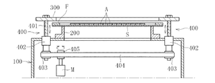
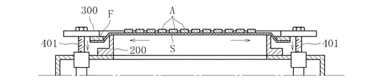
ウェーハシートを引き伸ばすためのエキスパンド装置として、例えば図5に示すものがある。図5に示すエキスパンド装置は、エキスパンド装置本体100の上部に固定された環状の固定部材200と、固定部材200の外径よりも大きい内径を有する環状の加圧部材300と、加圧部材300を昇降させる昇降機構400等を備えている。
An example of an expanding apparatus for stretching a wafer sheet is shown in FIG. The expanding apparatus shown in FIG. 5 includes an
前記昇降機構400は、互いに進退可能に螺合した雄ネジ部(送りネジ)401と雌ネジ部(ナット)402を複数組有する。雄ネジ部401の上端は、加圧部材300の下面にボルトなどで固定されている。一方、雌ネジ部402は、エキスパンド装置本体100の設けた孔に回転可能に挿嵌されている。各雌ネジ部402にはプーリ403が一体に設けられ、各プーリ403にベルト404が架け渡されている。また、ベルト404には、昇降用モータMの軸に設けたプーリ405が圧接している。この昇降用モータMの回転力を、ベルト404を介して各プーリ403及び雌ネジ部402に伝達することによって、雄ネジ部401が昇降するように構成されている(例えば、特許文献1の図11及び図12参照)。
The
図6に示すように、複数の半導体チップAを接着したウェーハシートSは、その周縁部をリングフレームFに固定されている。このリングフレームFをエキスパンド装置に搬入する場合は、図示しない搬送手段によってリングフレームFを保持し、エキスパンド装置に搬入する。詳しくは、リングフレームFに固定されたウェーハシートSを加圧部材300と固定部材200の間に搬入し、固定部材200の上に載置する。
As shown in FIG. 6, the wafer sheet S to which a plurality of semiconductor chips A are bonded is fixed to the ring frame F at the periphery. When the ring frame F is carried into the expanding apparatus, the ring frame F is held by a conveying means (not shown) and carried into the expanding apparatus. Specifically, the wafer sheet S fixed to the ring frame F is carried between the
以下、上記エキスパンド装置によって、ウェーハシートをエキスパンドする動作を説明する。図5の昇降用モータMを回転させることにより、ベルト404を介して各プーリ403及び各雌ネジ部402を回転させて、雄ネジ部401を降下させる。この雄ネジ部401の降下に伴って、図7に示すように、加圧部材300がリングフレームFを押し下げる。これにより、ウェーハシートSが放射状に引き伸ばされ、半導体チップA相互間が拡大される。
Hereinafter, the operation of expanding the wafer sheet by the above expanding apparatus will be described. 5 is rotated, the
また、近年では、図8に示すように、サイズの切り換えを目的として、加圧部材を2つのリング体に分割して、これらのリング体の間にリングフレームFを挟持するものもある(特許文献2)。すなわち、加圧部材は、加圧リング600とベースリング700の2つのリング体から構成される。加圧リング600は、一対の半円弧状の分割体600a、600bとからなる。ベースリング700は昇降板710に取付けられ、加圧リング600はベースリング700にねじ止めされている。昇降板710の4隅には、昇降機構720が設けられており、この昇降機構720が作動することによって、加圧リング600とベースリング700とが一体的に上下動する。
In recent years, as shown in FIG. 8, for the purpose of switching the size, the pressure member is divided into two ring bodies and a ring frame F is sandwiched between these ring bodies (patent). Reference 2). That is, the pressure member is composed of two ring bodies, a
そして、リングフレームFをエキスパンド装置に搬入する場合は、リングフレームFを加圧リング600とベースリング700の間に搬入する。そして、昇降機構720の雄ネジ部を降下させることにより、加圧リング600及びベースリング700がリングフレームFを押し下げる。これにより、ウェーハシートSが放射状に引き伸ばされ、半導体チップA相互間が拡大される。
特許文献2に記載のエキスパンド装置において、リングフレームFを搬入する場合は、図示しない搬送手段によってリングフレームFを保持し、図9の左から右へ移送してエキスパンド装置に搬入する。図9において、一点鎖線Lによって囲まれる領域は、リングフレームFを搬入・搬出する際のリングフレームFの通過領域Zである。また、同図において、符号P1〜P4は、前記加圧リング600をベースリング700に固定したねじ部の位置を示す。つまり、符号P1〜P4は、平面視した状態で、ねじ部の配設位置を示している。
In the expanding apparatus described in
すなわち、これら4つのねじ部(P1〜P4)は、搬入・搬出されるリングフレームFと干渉しないように、前記通過領域Zの外側に配設している。 That is, these four screw portions (P1 to P4) are arranged outside the passage region Z so as not to interfere with the ring frame F that is carried in and out.
また、図9において、ハッチング部にて示すのが、加圧部材(加圧リング)600がリングフレームFを押圧する際にリングフレームFと接触する押圧面610,620である。このため、前記したようなねじ部の配置では、前記押圧面610,620の周囲に均等に配設することができない。このような場合、エキスパンドする際に加圧リング600には均一に荷重が負荷されず、加圧リング600のリングフレーム搬入側に不均一な反りが生じ、押圧面610,620に均一な押圧力を作用させることができない。従って、ウェーハシートSを均等に引き伸ばすことができず、半導体チップA相互間を等間隔に拡大できなかったり、半導体チップAが斜めになったりする。
In FIG. 9, the hatching portions indicate
ウェーハシートSを均等に引き伸ばすことができない場合、半導体チップの座標位置がずれるおそれがある。ところで、上記ウェーハシートを引き伸ばした状態で、コレットによって半導体チップをピックアップする際、コレットは、半導体チップの座標位置のデータに基づいて、所定の半導体チップをピックアップし、リードフレーム等にボンディングを行う。すなわち、ウェーハシート上の各半導体チップAは、エキスパンド装置に搬送される前に、座標位置が管理されている。従って、半導体チップAの座標位置がずれると、ピックアップの際の位置決めに時間を要するという問題がある。 If the wafer sheet S cannot be stretched uniformly, the coordinate position of the semiconductor chip may be shifted. By the way, when a semiconductor chip is picked up by a collet in a state where the wafer sheet is stretched, the collet picks up a predetermined semiconductor chip based on the data of the coordinate position of the semiconductor chip and bonds it to a lead frame or the like. That is, the coordinate position of each semiconductor chip A on the wafer sheet is managed before being transferred to the expanding apparatus. Therefore, if the coordinate position of the semiconductor chip A is shifted, there is a problem that it takes time for positioning at the time of pickup.
そこで、本発明は上記課題に鑑みて、加圧リングに不均一な反りが生じるのを防止することができ、ウェーハシートを均等に引き伸ばすことができるエキスパンド装置を提供する。 Therefore, in view of the above problems, the present invention provides an expanding apparatus that can prevent uneven warping of the pressure ring and can uniformly stretch the wafer sheet.
本発明のエキスパンド装置は、固定リングと、固定リングの外周側に配設される加圧リングとを備え、昇降手段にて加圧リングを降下させることによって、電子部品を接着した伸縮性シートを固定リング側へ押し付けて、この伸縮性シートを引き伸ばすように構成したエキスパンド装置において、前記加圧リングが降下する際に、加圧リングの降下に連動して加圧リングに係合して、加圧リングの水平状態を維持する係合手段を設けたものである。 The expanding device of the present invention includes a fixing ring and a pressure ring disposed on the outer peripheral side of the fixing ring, and lowers the pressure ring by an elevating means to thereby attach an elastic sheet to which electronic components are bonded. In the expanding device configured to press the fixing ring and stretch the stretchable sheet, when the pressure ring is lowered, the pressure ring is engaged with the pressure ring to be added. The engagement means for maintaining the horizontal state of the pressure ring is provided.
本発明のエキスパンド装置によれば、加圧リングの降下に連動して加圧リングに係合する係合手段を設けたことにより、加圧リングの下降中及び下降後において、加圧リングに不均一な反りが生じるのを防止することができ、水平状態を維持することができる。これにより、加圧リングは、伸縮性シートに対して周方向に均一に力を付与することができる。 According to the expanding device of the present invention, the engagement means that engages the pressure ring in conjunction with the lowering of the pressure ring is provided, so that the pressure ring is incapable of being moved during and after the pressure ring is lowered. Uniform warpage can be prevented and a horizontal state can be maintained. Thereby, the pressure ring can uniformly apply force to the stretchable sheet in the circumferential direction.
前記昇降手段は、ベースリングと、このベースリングに連結された加圧リングとを昇降させる昇降機構とを備えることができる。 The elevating means may include a base ring and an elevating mechanism that elevates and lowers a pressure ring connected to the base ring.
前記係合手段は、ベースリングに設けられるラチェット部材を備え、このラチェット部材は、加圧リングの降下に伴って揺動して加圧リングに係合し、加圧リングの上昇に伴って揺動して加圧リングの係合が解除されるものとすることができる。すなわち、加圧リングを上下動させることによって、自動的に係合及び解除を行うことができる。 The engaging means includes a ratchet member provided on the base ring. The ratchet member swings as the pressure ring descends to engage the pressure ring, and swings as the pressure ring rises. The engagement of the pressure ring can be released by moving. That is, the engagement and release can be automatically performed by moving the pressure ring up and down.
前記加圧リングに、前記係合手段のラチェット部材が係合する座ぐり部を設けることができる。これにより、係合手段が座ぐり部に係合した場合において、係合手段が加圧リングの上面から突出するのを防止することができる。この場合、前記座ぐり部の底面は、外径から内径に向かって上昇するテーパ面とすることができる。これにより、座ぐり部のテーパ面がラチェット部材の揺動をガイドすることができる。 A counterbore portion with which the ratchet member of the engaging means is engaged can be provided on the pressure ring. Thereby, when the engaging means is engaged with the counterbore, it is possible to prevent the engaging means from protruding from the upper surface of the pressure ring. In this case, the bottom surface of the spot facing portion can be a tapered surface that rises from the outer diameter toward the inner diameter. Thereby, the taper surface of the counterbore part can guide rocking | fluctuation of a ratchet member.
加圧リングが少なくとも2つの分割体からなり、各分割体がベースリングに連結されるため、加圧リングのサイズの調節ができる。ところで、加圧リングにおいて、リングフレームが搬入・搬出される通過領域には加圧リングとベースリングとの連結部材を配設することができない。このため、分割体の一方の周方向端部が自由状態とされ、リングフレームの下降時に上方に反りが生じやすい。そこで、本発明では、特に加圧リングに反りが発生しやすい部位を水平状態に維持する係合手段にて係合することができる。 Since the pressure ring is composed of at least two divided bodies and each divided body is connected to the base ring, the size of the pressure ring can be adjusted. By the way, in the pressure ring, a connecting member between the pressure ring and the base ring cannot be disposed in a passing region where the ring frame is carried in / out. For this reason, one circumferential direction edge part of a division body is made into a free state, and when a ring frame descends, it tends to warp upward. Therefore, in the present invention, it is possible to engage with the engaging means that maintains a horizontal state at a portion where the pressure ring is likely to be warped.
本発明では、加圧リングは、伸縮性シートに対して周方向に均一に力を付与することができるため、ウェーハシートを均等に引き伸ばすことができる。これにより、電子部品相互間を等間隔に拡大でき、電子部品を水平状態とすることができる。また、電子部品の座標位置ずれを防止でき、電子部品のピックアップの際の位置決めを迅速に行うことができる。 In the present invention, the pressure ring can uniformly apply a force to the stretchable sheet in the circumferential direction, so that the wafer sheet can be stretched uniformly. Thereby, between electronic components can be expanded at equal intervals and an electronic component can be made into a horizontal state. Further, the coordinate position shift of the electronic component can be prevented, and the electronic component can be quickly positioned when picked up.
前記昇降手段は、ベースリングと、このベースリングに係合手段を介して係合一体化された加圧リングとを昇降させる昇降機構とを備えたものとすると、加圧リングの昇降に連動して確実に係合手段を作動させることができる。 Assuming that the elevating means includes a base ring and an elevating mechanism for elevating and lowering the base ring and a pressure ring engaged with and integrated with the base ring via the engaging means, the elevating means interlocks with the elevating of the pressure ring. Thus, the engaging means can be operated reliably.
前記係合手段は、ベースリングに設けられるラチェット部材を備えたものとすると、簡単な構成で係合手段を設けることができる。 If the engagement means includes a ratchet member provided on the base ring, the engagement means can be provided with a simple configuration.
前記加圧リングに、前記係合手段のラチェット部材が係合する座ぐり部を設けて、外径から内径に向かって上昇するテーパ面とすると、座ぐり部のテーパ面がラチェット部材の揺動をガイドすることができて、係合手段をスムーズに加圧リングに係合することができる。また、係合手段が座ぐり部に係合した場合において、係合手段が加圧リングの上面から突出するのを防止すると、装置のコンパクト化や、故障を防止することができる。 When the countersunk portion that engages with the ratchet member of the engaging means is provided on the pressure ring so that the tapered surface rises from the outer diameter toward the inner diameter, the tapered surface of the counterbore portion swings the ratchet member. The engaging means can be smoothly engaged with the pressure ring. Further, when the engaging means is engaged with the counterbore, preventing the engaging means from protruding from the upper surface of the pressure ring can reduce the size of the apparatus and prevent failure.
特に、加圧リングに反りが発生しやすい部位を係合手段のラチェット部材にて係合すると、一層伸縮性シートに対して周方向に均一に力を付与することができ、伸縮性シートを一層均等に引き伸ばすことができる。 In particular, when a portion where the pressure ring is likely to warp is engaged with the ratchet member of the engaging means, a force can be uniformly applied to the stretchable sheet in the circumferential direction. Can be stretched evenly.
以下本発明の実施の形態を図1〜図4に基づいて説明する。 Hereinafter, embodiments of the present invention will be described with reference to FIGS.
図1に本発明のエキスパンド装置の要部断面図を示し、この装置は、昇降手段にて加圧リングを降下させることによって、電子部品を接着した伸縮性シートを固定リング側へ押し付けて、この伸縮性シートを引き伸ばすものである。 FIG. 1 shows a cross-sectional view of an essential part of an expanding apparatus according to the present invention, in which the pressing ring is lowered by an elevating means to press an elastic sheet to which an electronic component is bonded to the fixing ring side. The stretchable sheet is stretched.
このようなエキスパンド装置は、図1に示すように、回転ベース3と、この回転ベース3に固定された固定リング1と、この固定リング1に対して昇降可能に構成された加圧リング2と、加圧リング2を昇降可能とする昇降手段4とを備える。
As shown in FIG. 1, such an expanding apparatus includes a
回転ベース3は、図示しない周知のX方向駆動機構およびY方向駆動機構を備え、さらに、θ方向駆動機構を備えている。回転ベース3は、断面L字状のリング体であり、水平部8と、水平部8の外周縁から延びる鉛直部9とからなり、鉛直部9の先端部には、押圧ブロック10が固定されている。回転ベース3上に、電子部品を接着した伸縮性シートSを載置する固定リング1を備えている。本実施形態では、伸縮性シートSは、前工程でダイシング装置のダイサによって半導体ウェーハを切断分離した多数の半導体チップAが接着されているウェーハシートであり、ウェーハシートは、その周縁部をリングフレーム5に固定されている(図4参照)。
The
固定リング1は、回転ベース3に固定される第1水平部20と、第1水平部20の内径側に配設される円筒状の大径部6と、大径部6の先端縁に設けられる第2水平部21と、第2水平部21の内径側に配設される小径部7とを備えている。小径部7の外径は、リングフレーム5の内径よりも小さくなるようにしている。
The fixing ring 1 is provided at a first
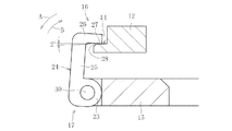
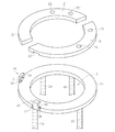
加圧リング2は、固定リング1の外周側に配設され、降下することによって、リングフレーム5を固定リング側へ押し付けて、伸縮性シートSを引き伸ばすものである。この加圧リング2は2つの分割体からなり(図4参照)、半円弧状の本体部11を備える。本体部11は、その内径側に下方に開口する周方向溝13が形成されるとともに、一方の周方向端部の外径側に下方開口状の切欠部22が形成され、この切欠部22にブロック体12が嵌合している。ブロック体12には、図2に示すように、その外面側に切欠き(座ぐり)14が設けられている。また、切欠き14の切欠き底面27は、外径から内径に向かって上昇するテーパ面となっており、このテーパ面は水平方向に対して約2°傾斜している。切欠き底面27の外端縁には、さらに面取り28がなされている。
The
昇降手段4は、図3に示すように、加圧リング2の下方に配置されるベースリング15と、このベースリング15に係合一体化された加圧リング2とを昇降させる4つの昇降機構18とを備えている。前記ベースリング15と加圧リング2の内径は、前記固定リング1の小径部7の外径よりも大きく、かつ、リングフレーム5の内径よりも大きく設定されている。ベースリング15には、加圧リング2が降下する際に、加圧リング2の降下に連動して加圧リング2に係合する係合手段16を設けている。これにより、係合手段16が座ぐり部14に係合して、加圧リング2の水平状態を維持することができる。本実施形態では、図2や図3に示すように、ベースリング15にラチェット部材17を設けており、このラチェット部材17と座ぐり部14とで係合手段16を構成している。すなわち、このラチェット部材17は、枢支部23と、枢支部23から延びるL字状のフック部24とからなる。フック部24は、枢支部23から延びる平板状本体25と、この本体25の先端部から直角に曲がる係合部26とからなる。そして、ベースリング15に、切欠部29を設け、この切欠部29にラチェット部材17の枢支部23が嵌合され、枢支部23に挿通されるピン30をベースリング15に固定することによって、ラチェット部材17が枢支部23を中心に矢印A、Bのように揺動する。また、ラチェット部材17は、図示省略の弾発部材にて常時矢印Aの方向に付勢されている。そして、加圧リング2の下降に伴って、ラチェット部材17が押圧ブロック10に押圧されることにより、弾発部材の弾性力に抗して矢印Bの方向に揺動して加圧リング2の座ぐり部14に係合する。一方、加圧リング2の上昇に伴って、弾発部材の弾性力にてラチェット部材17が矢印Aの方向に揺動して加圧リング2の係合が解除される。
As shown in FIG. 3, the elevating
昇降機構18は、互いに進退可能に螺合した雄ネジ部(送りネジ)と雌ネジ部(ナット)を複数組有する。雄ネジ部の上端は、ベースリング15の下面にボルトなどで固定されている。一方、雌ネジ部は、エキスパンド装置本体(図示省略)の設けた孔に回転可能に挿嵌されている。すなわち、図8に示した従来の昇降機構と同様の構成としている。
The elevating
図4において、一点鎖線Lによって囲まれる領域は、リングフレーム5を搬入・搬出する際のリングフレーム5の通過領域Zである。また、同図において、符号P1〜P4は、加圧リング2をベースリング15に固定したねじ部の位置を示す。つまり、符号P1〜P4は、平面視した状態で、ねじ部の配設位置を示している。これら4つのねじ部(P1〜P4)は、搬入・搬出されるリングフレーム5と干渉しないように、前記通過領域Zの外側に配設されている。図4において、ハッチング部にて示すのが、加圧リング2がリングフレーム5を押圧する際にリングフレーム5と接触する押圧面30、31である。
In FIG. 4, a region surrounded by a one-dot chain line L is a passing region Z of the
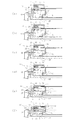
次に、図1に示したエキスパンド装置によって、ウェーハシートをエキスパンドする方法について説明する。まず、複数の半導体チップAを接着したウェーハシートSは、その周縁部をリングフレーム5に固定されている。このリングフレーム5をエキスパンド装置に搬入する場合は、図示しない搬送手段によってリングフレーム5を保持し、移送してエキスパンド装置に搬入する。すなわち、図1(a)に示すように、リングフレーム5に固定されたウェーハシートSを加圧リング2とベースリング15との間に搬入する。
Next, a method for expanding a wafer sheet using the expanding apparatus shown in FIG. 1 will be described. First, the wafer sheet S to which a plurality of semiconductor chips A are bonded has its peripheral edge fixed to the
次に、図示省略の昇降用モータを回転させることにより、ベルトを介して各プーリ及び各雌ネジ部を回転させて、ベースリング15を降下させる。この雄ネジ部の降下に伴って、図1に示すように、加圧リング2とベースリング15とが一体的に下降して、加圧リング2がリングフレーム5を押し下げる。このとき、図1(b)に示すように、押圧ブロック10がラチェット部材17を押圧して、枢支部23を中心に矢印B(図2参照)の方向に揺動する。このように、加圧リング2の下降に伴って、図1(b)のように、枢支部23を中心としてラチェット部材17が揺動して、図1(c)のようにラチェット部材17の係合部26が加圧リング2の座ぐり部14に係合する。この係合状態では、ラチェット部材17のフック部24の外面31が押圧ブロック10の内面32と接触した状態となる。
Next, by rotating a lifting motor (not shown), the pulleys and the female screw portions are rotated via the belt, and the
そして、図1(c)に示すように、ラチェット部材17の係合部26が座ぐり部14に係合した状態で、図1(d)(e)のように、加圧リング2とベースリング15は下降し、最終的に図1(f)に示すように、加圧リング2がリングフレーム5を押し下げる。なお、これにより、ウェーハシートSが放射状に引き伸ばされ、半導体チップA相互間が拡大される。加圧リング2とベースリング15との下降の際には、フック部24の外面31が押圧ブロック10の内面32に対して摺動することになる。
Then, as shown in FIG. 1C, in a state where the engaging
その後、ベルトを介して各プーリ及び各雌ネジ部を回転させて、雄ネジ部を上昇させる。この雄ネジ部の上昇に伴って、加圧リング2とベースリング15とが一体的に上昇する。このとき、図1(b)のように、フック部24が押圧ブロック10よりもある位置を越えたとき、弾発部材によってラチェット部材17は枢支部23を中心に矢印A(図2参照)の方向に揺動する。このように、加圧リング2の上昇に伴って、枢支部23を中心としてラチェット部材17が揺動して、ラチェット部材17の係合部26が加圧リング2の座ぐり部14から離脱し、図1(a)に示す初期状態となる。
Then, each pulley and each internal thread part are rotated via a belt, and an external thread part is raised. As the male screw part rises, the
本発明では、加圧リング2の降下に連動して加圧リング2に係合する係合手段16を設けたことにより、加圧リング2の下降中及び下降後において、加圧リング2に不均一な反りが生じるのを防止することができ、水平状態を維持することができる。これにより、加圧リング2は、ウェーハシートSに対して周方向に均一に力を付与することができるため、ウェーハシートSを均等に引き伸ばすことができる。従って、電子部品相互間を等間隔に拡大でき、電子部品を水平状態とすることができる。また、電子部品の座標位置ずれを防止でき、電子部品のピックアップの際の位置決めを迅速に行うことができる。
In the present invention, the engagement means 16 that engages with the
前記昇降手段は、ベースリング15と、このベースリング15に係合手段16を介して係合一体化された加圧リング2とを昇降させる昇降機構18とを備えているので、加圧リング2の昇降に連動して確実に係合手段16を作動させることができる。
The elevating means includes a
前記係合手段16は、ベースリング15に設けられるラチェット部材17を備え、このラチェット部材17は、加圧リング2の昇降に伴って揺動して加圧リング2に係合し、加圧リング2の上昇に伴って揺動して加圧リング2の係合が解除されるものとすると、簡単な構成で係合手段16を設けることができる。
The engaging means 16 includes a
前記加圧リング2に、前記係合手段16のラチェット部材17が係合する座ぐり部14を設けているので、係合手段16が座ぐり部14に係合しても係合手段16が加圧リング2の上面から突出するのを防止することができ、装置のコンパクト化や、故障を防止することができる。また、座ぐり部14を、外径から内径に向かって上昇するテーパ面としているので、座ぐり部14のテーパ面がラチェット部材17の揺動をガイドすることができて、係合手段16をスムーズに加圧リング2に係合することができる。
Since the
加圧リング2が少なくとも2つの分割体からなり、各分割体がベースリング15に連結され、各分割体の端部に前記係合手段16を設けると、特に、加圧リング2に反りが発生しやすい部位を係合手段16のラチェット部材17にて係合することができる。これにより、一層ウェーハシートSに対して周方向に均一に力を付与することができ、ウェーハシートSを一層均等に引き伸ばすことができる。
When the
以上、本発明の実施形態につき説明したが、本発明は前記実施形態に限定されることなく種々の変形が可能であって、例えば、係合手段16の数及び配置位置は、加圧リング2の水平状態を維持できる範囲で任意に設定することができる。また、係合手段16は、加圧リング2の上下動に連動して、係合及び解除するものであれば、別の駆動手段にて駆動させてもよい。また、座ぐり部14を省略して係合手段16が加圧リング2の上面から突出するようにしてもよい。係合手段16は、加圧リング2とベースリング15とに係合するものであれば、ラチェット部材17に限らず他の機構であってもよい。
As described above, the embodiment of the present invention has been described. However, the present invention is not limited to the above-described embodiment, and various modifications can be made. It can be arbitrarily set within a range in which the horizontal state can be maintained. Further, the engaging
1 固定リング
2 加圧リング
4 昇降手段
14 座ぐり部
15 ベースリング
16 係合手段
17 ラチェット部材
18 昇降機構
S 伸縮性シート
DESCRIPTION OF SYMBOLS 1
Claims (6)
昇降手段にて加圧リングを降下させることによって、電子部品を接着した伸縮性シートを固定リング側へ押し付けて、この伸縮性シートを引き伸ばすように構成したエキスパンド装置において、
前記加圧リングが降下する際に、加圧リングの降下に連動して加圧リングに係合して、加圧リングの水平状態を維持する係合手段を設けたことを特徴とするエキスパンド装置。 A fixing ring, and a pressure ring disposed on the outer peripheral side of the fixing ring,
In the expanding apparatus configured to push the stretchable sheet to which the electronic component is bonded to the fixing ring side by lowering the pressure ring by the lifting means, and to stretch the stretchable sheet,
An expanding device is provided, wherein when the pressure ring is lowered, an engagement means is provided that engages with the pressure ring in conjunction with the lowering of the pressure ring and maintains the horizontal state of the pressure ring. .
Priority Applications (1)
| Application Number | Priority Date | Filing Date | Title |
|---|---|---|---|
| JP2008217949A JP5269522B2 (en) | 2008-08-27 | 2008-08-27 | Expanding device |
Applications Claiming Priority (1)
| Application Number | Priority Date | Filing Date | Title |
|---|---|---|---|
| JP2008217949A JP5269522B2 (en) | 2008-08-27 | 2008-08-27 | Expanding device |
Publications (2)
| Publication Number | Publication Date |
|---|---|
| JP2010056207A true JP2010056207A (en) | 2010-03-11 |
| JP5269522B2 JP5269522B2 (en) | 2013-08-21 |
Family
ID=42071828
Family Applications (1)
| Application Number | Title | Priority Date | Filing Date |
|---|---|---|---|
| JP2008217949A Expired - Fee Related JP5269522B2 (en) | 2008-08-27 | 2008-08-27 | Expanding device |
Country Status (1)
| Country | Link |
|---|---|
| JP (1) | JP5269522B2 (en) |
Cited By (3)
| Publication number | Priority date | Publication date | Assignee | Title |
|---|---|---|---|---|
| JP2015216324A (en) * | 2014-05-13 | 2015-12-03 | 株式会社ディスコ | Chuck table of cutting device |
| CN112820685A (en) * | 2020-12-30 | 2021-05-18 | 江苏新智达新能源设备有限公司 | Get brilliant blue membrane fixed establishment of wafer |
| CN117230433A (en) * | 2023-11-15 | 2023-12-15 | 无锡尚积半导体科技有限公司 | CVD wafer bearing mechanism |
Citations (3)
| Publication number | Priority date | Publication date | Assignee | Title |
|---|---|---|---|---|
| JPH0574842A (en) * | 1991-09-13 | 1993-03-26 | Matsushita Electric Ind Co Ltd | Positioning device of lead frame at wire bonder |
| JPH07231003A (en) * | 1994-02-18 | 1995-08-29 | Toshiba Seiki Kk | Wafer sheet expanding apparatus |
| JP2006310438A (en) * | 2005-04-27 | 2006-11-09 | Towa Corp | Expansion apparatus for electronic components |
-
2008
- 2008-08-27 JP JP2008217949A patent/JP5269522B2/en not_active Expired - Fee Related
Patent Citations (3)
| Publication number | Priority date | Publication date | Assignee | Title |
|---|---|---|---|---|
| JPH0574842A (en) * | 1991-09-13 | 1993-03-26 | Matsushita Electric Ind Co Ltd | Positioning device of lead frame at wire bonder |
| JPH07231003A (en) * | 1994-02-18 | 1995-08-29 | Toshiba Seiki Kk | Wafer sheet expanding apparatus |
| JP2006310438A (en) * | 2005-04-27 | 2006-11-09 | Towa Corp | Expansion apparatus for electronic components |
Cited By (4)
| Publication number | Priority date | Publication date | Assignee | Title |
|---|---|---|---|---|
| JP2015216324A (en) * | 2014-05-13 | 2015-12-03 | 株式会社ディスコ | Chuck table of cutting device |
| CN112820685A (en) * | 2020-12-30 | 2021-05-18 | 江苏新智达新能源设备有限公司 | Get brilliant blue membrane fixed establishment of wafer |
| CN117230433A (en) * | 2023-11-15 | 2023-12-15 | 无锡尚积半导体科技有限公司 | CVD wafer bearing mechanism |
| CN117230433B (en) * | 2023-11-15 | 2024-03-01 | 无锡尚积半导体科技有限公司 | CVD wafer bearing mechanism |
Also Published As
| Publication number | Publication date |
|---|---|
| JP5269522B2 (en) | 2013-08-21 |
Similar Documents
| Publication | Publication Date | Title |
|---|---|---|
| JP4677275B2 (en) | Expanding device for electronic components | |
| JP6186256B2 (en) | Processing equipment | |
| CN1943025A (en) | Wafer processing device and wafer processing method | |
| TWI566315B (en) | Wafer mounted apparatus with high yield and method thereof | |
| JP2009302232A (en) | Mounting device | |
| KR102150406B1 (en) | Automatic handling apparatus | |
| JP5269522B2 (en) | Expanding device | |
| JP2007048828A (en) | Deformation processing apparatus and deformation processing method of plate-shaped structure | |
| CN101061528A (en) | Substrate holding structure | |
| KR101426883B1 (en) | Apparatus for holding material for multi axis position | |
| JPH11297793A (en) | Chip thrust-up device and die-bonding device using the same | |
| JP2012186505A (en) | Component supply device | |
| JP2020072125A (en) | Electronic component pick-up device and mounting device | |
| CN109461688A (en) | Wafer conveying device and its working method | |
| JP2006156806A (en) | Method and device for picking up pellet | |
| JP2012049402A (en) | Manufacturing device of semiconductor device, semiconductor device pickup method, and semiconductor device manufacturing method | |
| TW201504641A (en) | Electronic device operation apparatus and the operation equipment applied thereof | |
| JP2005268274A (en) | Turntable mechanism | |
| KR20200075502A (en) | wafer size expanding apparatus and wafer alignment apparatus including the same | |
| JP2011211055A (en) | Expand device | |
| KR101228178B1 (en) | Polishing apparatus | |
| JP5652868B2 (en) | Wafer pallet, component mounter, and dicing sheet mounting method | |
| JP2018074120A (en) | Wafer transfer and holding device | |
| JP4285219B2 (en) | Seat expansion device | |
| JP2009252890A (en) | Component supply device |
Legal Events
| Date | Code | Title | Description |
|---|---|---|---|
| A621 | Written request for application examination |
Free format text: JAPANESE INTERMEDIATE CODE: A621 Effective date: 20110705 |
|
| A977 | Report on retrieval |
Free format text: JAPANESE INTERMEDIATE CODE: A971007 Effective date: 20121015 |
|
| A131 | Notification of reasons for refusal |
Free format text: JAPANESE INTERMEDIATE CODE: A131 Effective date: 20121018 |
|
| A521 | Written amendment |
Free format text: JAPANESE INTERMEDIATE CODE: A523 Effective date: 20121114 |
|
| A131 | Notification of reasons for refusal |
Free format text: JAPANESE INTERMEDIATE CODE: A131 Effective date: 20121221 |
|
| A521 | Written amendment |
Free format text: JAPANESE INTERMEDIATE CODE: A523 Effective date: 20121226 |
|
| TRDD | Decision of grant or rejection written | ||
| A01 | Written decision to grant a patent or to grant a registration (utility model) |
Free format text: JAPANESE INTERMEDIATE CODE: A01 Effective date: 20130426 |
|
| A61 | First payment of annual fees (during grant procedure) |
Free format text: JAPANESE INTERMEDIATE CODE: A61 Effective date: 20130508 |
|
| R150 | Certificate of patent or registration of utility model |
Free format text: JAPANESE INTERMEDIATE CODE: R150 Ref document number: 5269522 Country of ref document: JP Free format text: JAPANESE INTERMEDIATE CODE: R150 |
|
| R250 | Receipt of annual fees |
Free format text: JAPANESE INTERMEDIATE CODE: R250 |
|
| R250 | Receipt of annual fees |
Free format text: JAPANESE INTERMEDIATE CODE: R250 |
|
| R250 | Receipt of annual fees |
Free format text: JAPANESE INTERMEDIATE CODE: R250 |
|
| R250 | Receipt of annual fees |
Free format text: JAPANESE INTERMEDIATE CODE: R250 |
|
| LAPS | Cancellation because of no payment of annual fees |