JP2010048588A - Method and device for calculating of imbalance amount of rotating body - Google Patents
Method and device for calculating of imbalance amount of rotating body Download PDFInfo
- Publication number
- JP2010048588A JP2010048588A JP2008211303A JP2008211303A JP2010048588A JP 2010048588 A JP2010048588 A JP 2010048588A JP 2008211303 A JP2008211303 A JP 2008211303A JP 2008211303 A JP2008211303 A JP 2008211303A JP 2010048588 A JP2010048588 A JP 2010048588A
- Authority
- JP
- Japan
- Prior art keywords
- unbalance amount
- rotating body
- rotation speed
- unbalance
- data
- Prior art date
- Legal status (The legal status is an assumption and is not a legal conclusion. Google has not performed a legal analysis and makes no representation as to the accuracy of the status listed.)
- Granted
Links
Images

Abstract
Description
本発明は、振動データと影響係数とに基づいてアンバランス量を算出する回転体のアンバランス量算出方法及び装置に関する。 The present invention relates to an unbalance amount calculation method and apparatus for a rotating body that calculates an unbalance amount based on vibration data and an influence coefficient.
例えば過給機などの高速回転機械の製造においては、製品の高速回転時のバランス性能を検査・修正するために、高速回転バランス試験を実施してアンバランス量を測定し、アンバランス修正を行う。従来のアンバランス修正方法と装置を開示するものとして、下記特許文献1がある。 For example, in the manufacture of high-speed rotating machines such as turbochargers, in order to inspect and correct the balance performance at the time of product high-speed rotation, a high-speed rotation balance test is performed to measure the unbalance amount and correct the unbalance. . Patent Document 1 below discloses a conventional unbalance correction method and apparatus.
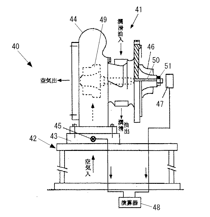
図4は、下記特許文献1に開示されたアンバランス修正装置40の構成を示す図である。このアンバランス修正装置40は、過給機41用の修正装置として構成されており、振動台42の上にタービン車室取付板43を介して固定されたタービン車室44と、タービン車室取付板43に取り付けられた加速度センサ45と、過給機41のコンプレッサインペラ46の先端近傍に配置される回転検出器47と、加速度センサ45と回転検出器47からの検出信号に基づいてアンバランス量を演算する演算器48とを備える。
FIG. 4 is a diagram illustrating a configuration of an
上記のアンバランス修正装置40によりアンバランス修正を行う場合、タービン車室44に空気を導入して過給機41のタービンインペラ49を回転させることで、タービンインペラ49、シャフト50及びコンプレッサインペラ46からなる過給機ロータを回転させ、アンバランス計測のための所定の回転速度に達したら、加速度センサ45で加速度(振動)を検出するとともに回転検出器47で回転角度を検出し、その検出信号に基づいて演算器48により、アンバランス量を演算する。
When the unbalance correction is performed by the
ここで、アンバランス量は、アンバランスの大きさ(重さ)及び回転体(この例では過給機ロータ)上の任意の基準位相に対する位相(角度)とからなる物理量である。
演算器48によりアンバランス量が算出されたら、このアンバランス量に基づいて、コンプレッサインペラ46の先端部に設けられたナット51の一部を除去加工することで、アンバランスを修正する。
Here, the unbalance amount is a physical quantity including the magnitude (weight) of unbalance and a phase (angle) with respect to an arbitrary reference phase on the rotating body (supercharger rotor in this example).
When the unbalance amount is calculated by the
上述した従来のアンバランス測定においては、回転体の回転数をある特定の回転数に設定して振動を計測し、その特定の回転数に対応した影響係数Fを使用してアンバランス量を算出していた。ここで、影響係数Fとは、回転体のアンバランス量Uが振動Vに与える影響を示す伝達関数をいい、アンバランス量Uは、U=V/Fで求めることができる。 In the above-described conventional unbalance measurement, the rotational speed of the rotating body is set to a specific rotational speed, vibration is measured, and an unbalance amount is calculated using an influence coefficient F corresponding to the specific rotational speed. Was. Here, the influence coefficient F refers to a transfer function indicating the influence of the unbalance amount U of the rotating body on the vibration V, and the unbalance amount U can be obtained by U = V / F.
アンバランス計測において回転体の回転数は特定の回転数を維持するように制御されるものの、実際のアンバランス計測時には、回転体の回転数は完全に一定とはならず、ある程度の不安定性がある。ところが、上述したように従来のアンバランス計測では特定回転数での影響係数を用いてアンバランス量を算出するため、真のアンバランス量との誤差が大きく、計測精度が悪いという問題があった。 Although the rotational speed of the rotating body is controlled to maintain a specific rotational speed in unbalance measurement, the rotational speed of the rotating body is not completely constant during actual unbalance measurement, and there is some instability. is there. However, as described above, in the conventional unbalance measurement, since the unbalance amount is calculated using the influence coefficient at the specific rotation speed, there is a problem that the error from the true unbalance amount is large and the measurement accuracy is poor. .
本発明は、上記の問題に鑑みてなされたものであり、アンバランス量を精度良く算出することができる回転体のアンバランス算出方法及び装置を提供することを課題とする。 The present invention has been made in view of the above problems, and an object of the present invention is to provide a method and an apparatus for calculating an unbalance of a rotating body that can accurately calculate an unbalance amount.
上記の課題を解決するため、本発明のアンバランス算出方法及び装置は、以下の技術的手段を採用する。
(1)本発明は、回転体の振動データと、回転体のアンバランス量が振動に与える影響を示す影響係数とに基づいて、前記回転体のアンバランス量を算出する回転体のアンバランス量算出方法であって、所定範囲の回転数領域で回転数毎に影響係数F(N)を求め、回転する回転体の回転角度及び振動を検出して回転数毎の振動データV(N)を算出し、回転数毎の振動データV(N)と、それぞれの回転数に対応した影響係数F(N)とに基づいて、回転数毎のアンバランス量U(N)を算出し、得られた回転数毎のアンバランス量U(N)を平均化して、回転体のアンバランス量Uを算出する、ことを特徴とする。
In order to solve the above problems, the unbalance calculation method and apparatus of the present invention employ the following technical means.
(1) The present invention calculates the unbalance amount of the rotating body based on the vibration data of the rotating body and the influence coefficient indicating the influence of the unbalance amount of the rotating body on the vibration. In this calculation method, an influence coefficient F (N) is obtained for each rotational speed in a rotational speed region within a predetermined range, and the rotational angle and vibration of the rotating rotating body are detected to obtain vibration data V (N) for each rotational speed. The unbalance amount U (N) for each rotation speed is calculated and obtained based on the vibration data V (N) for each rotation speed and the influence coefficient F (N) corresponding to each rotation speed. The unbalance amount U (N) for each rotation number is averaged to calculate the unbalance amount U of the rotating body.
(2)上記のアンバランス算出方法において、回転数毎のアンバランス量U(N)を平均化する段階において、回転数毎のデータ数の頻度に基づいて各アンバランス量U(N)に重み付けを行って平均化する。 (2) In the above unbalance calculation method, in the stage of averaging the unbalance amount U (N) for each rotation speed, the unbalance amount U (N) is weighted based on the frequency of the number of data for each rotation speed. To average.
(3)上記のアンバランス算出方法において、回転数毎の各アンバランス量U(N)に重み付けを行う段階において、同一回転数において異なるアンバランス量のデータが複数ある場合、代表的に選択した一つのデータ、あるいは当該複数のデータのうちの一部または全部の平均値を、当該回転数におけるアンバランス量U(N)とする。 (3) In the above-described unbalance calculation method, when there is a plurality of data with different unbalance amounts at the same number of revolutions in the stage of weighting each unbalance amount U (N) for each number of revolutions, the representative method is selected. One data or an average value of a part or all of the plurality of data is set as an unbalance amount U (N) at the rotation speed.
(4)また本発明は、回転体の振動データと、回転体のアンバランス量が振動に与える影響を示す影響係数とに基づいて、前記回転体のアンバランス量を算出する回転体のアンバランス量算出装置であって、回転する回転体の回転角度及び振動を検出するデータ検出手段と、回転体のアンバランス量Uを算出する演算器とを備え、前記演算器は、データ検出手段からの検出データに基づいて回転数毎の振動データV(N)を算出し、回転数毎の振動データV(N)と、それぞれの回転数に対応した影響係数F(N)とに基づいて、回転数毎のアンバランス量U(N)を算出し、得られた回転数毎のアンバランス量U(N)を平均化して、回転体のアンバランス量Uを算出する、ことを特徴とする。 (4) Further, the present invention provides an unbalance of the rotating body that calculates the unbalance amount of the rotating body based on vibration data of the rotating body and an influence coefficient indicating an influence of the unbalance amount of the rotating body on the vibration. An amount calculation device, comprising: data detection means for detecting a rotation angle and vibration of a rotating rotating body; and a calculator for calculating an unbalance amount U of the rotating body. Based on the detection data, vibration data V (N) for each rotation speed is calculated. Based on the vibration data V (N) for each rotation speed and an influence coefficient F (N) corresponding to each rotation speed, rotation is performed. An unbalance amount U (N) for each number is calculated, and the obtained unbalance amount U (N) for each number of rotations is averaged to calculate the unbalance amount U of the rotating body.
(5)上記のアンバランス算出装置において、前記演算器は、回転数毎のアンバランス量U(N)を平均化する段階において、回転数毎のデータ数の頻度に基づいて各アンバランス量U(N)に重み付けを行って平均化する。 (5) In the above-described unbalance calculation device, the computing unit calculates each unbalance amount U based on the frequency of the number of data for each rotation number in the stage of averaging the unbalance amount U (N) for each rotation number. (N) is weighted and averaged.
(6)上記のアンバランス算出装置において、前記演算器は、回転数毎の各アンバランス量U(N)に重み付けを行う段階において、同一回転数において異なるアンバランス量のデータが複数ある場合、代表的に選択した一つのデータ、あるいは当該複数のデータのうちの一部または全部の平均値を、当該回転数におけるアンバランス量U(N)とする。 (6) In the above-described unbalance calculation apparatus, when the computing unit weights each unbalance amount U (N) for each rotation speed, and there are a plurality of data of different unbalance amounts at the same rotation speed, One data typically selected or an average value of a part or all of the plurality of data is set as an unbalance amount U (N) at the rotation speed.
上記の本発明の方法及び装置によれば、広い回転数領域で各回転数に対応した影響係数F(N)を計測しておき、回転数に応じた影響係数F(N)を使用してアンバランス量Uを算出する。これにより、アンバランス計測のための回転体の回転運転時に回転数が安定しなくても、回転数に応じた影響係数を使用してアンバランス量を算出するので、精度よくアンバランス量Uを計測することができる。 According to the method and apparatus of the present invention, the influence coefficient F (N) corresponding to each rotation speed is measured in a wide rotation speed region, and the influence coefficient F (N) corresponding to the rotation speed is used. An unbalance amount U is calculated. As a result, even if the rotational speed is not stable during the rotational operation of the rotating body for unbalance measurement, the unbalance amount is calculated using the influence coefficient corresponding to the rotational speed. It can be measured.
また、本発明の方法及び装置によれば、回転数毎のデータ数の頻度に基づいて各アンバランス量U(N)に重み付けを行って平均化するので、頻度の低い回転数の不安定なデータの影響が小さくなり、アンバランス量の算出精度を向上させることができる。 Further, according to the method and apparatus of the present invention, since each unbalance amount U (N) is weighted and averaged based on the frequency of the number of data for each number of revolutions, the unstable number of revolutions with low frequency is unstable. The influence of data is reduced, and the calculation accuracy of the unbalance amount can be improved.
また、本発明の本発明の方法及び装置によれば、同一回転数において異なるアンバランス量のデータが複数ある場合に、代表的に選択した一つのデータまたは平均値をその回転数におけるアンバランス量とすることで、計算に用いるデータを適正化するので、アンバランス量の算出精度を向上させることができる。 Further, according to the method and apparatus of the present invention, when there are a plurality of data having different unbalance amounts at the same rotational speed, the representatively selected one data or average value is converted to the unbalance amount at the rotational speed. By doing so, since the data used for the calculation is optimized, the calculation accuracy of the unbalance amount can be improved.
以下、本発明の好ましい実施形態を添付図面に基づいて詳細に説明する。なお、各図において共通する部分には同一の符号を付し、重複した説明を省略する。 Hereinafter, preferred embodiments of the present invention will be described in detail with reference to the accompanying drawings. In addition, the same code | symbol is attached | subjected to the common part in each figure, and the overlapping description is abbreviate | omitted.
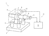
図1は、本発明の実施形態に関わる回転体7のアンバランス量算出装置10の構成を示す図である。図1において、アンバランス量算出装置10は、アンバランス計測装置1の一構成要素である。
FIG. 1 is a diagram illustrating a configuration of an unbalance
アンバランス計測装置1は、床面などに固定されたベース2と、ベース2上に固定されバネとして機能する棒状の複数(図示例で4本)のバネ部材3と、バネ部材3の上部にて固定及び支持されたマウント4と、アンバランス量算出装置10とを備える。
The unbalance measuring device 1 includes a
バネ部材3の本数及びバネ定数は、バネ部材3の材質(硬さ)やアンバランス計測を行う周波数(回転数)に応じて適切な数及び値に設定される。
マウント4は、回転体7を備えた回転機械6を装着し、しっかりと固定できるように構成されている。アンバランス計測の対象となる回転機械6は、例えば、過給機、圧縮機、タービン、モータなどである。
The number of
The
アンバランス計測を行う際の回転体7の回転駆動は、図示しない外部駆動装置で行う場合と、回転機械6自体が備えるモータ等の駆動源で行う場合とがある。
The rotational drive of the rotating
アンバランス量算出装置10は、振動を検出する振動センサ12と、回転体7の回転を検出する回転検出器11と、アンバランス量Uを演算する演算器13とを備える。
The unbalance
振動センサ12は、図示例ではマウントに取り付けられているが、回転機械6に取り付けることも可能である。振動センサ12は、従来のアンバランス計測において用いられていたのと同様に、振動を検出できる各種センサであればよく、例えば、加速度センサ、速度センサ、変位センサを単独で、あるいは組み合わせて用いることが可能である。
Although the
回転検出器11は、マウント4に装着された回転機械6の回転体7の軸8の近傍に配置され、その軸8上に設定された任意の基準位置からの位相(回転角)を検出することで、回転体7の回転角度と回転数を計測することができる。回転検出器11は、磁気センサや光センサなど各種のものを適用することが可能である。
The
上記の振動センサ12と回転検出器11により、本発明における「回転する回転体の回転角度及び振動を検出するデータ検出手段」が構成されている。
The
演算器13は、振動センサ12及び回転検出器11からの検出信号に基づいてアンバランス量Uを演算する。アンバランス量Uはアンバランスの大きさ(重さ)及び回転体7上の任意の基準位相に対する位相(角度)とからなる物理量である。演算器13によるアンバランス量の算出は、以下のようにして行う。
The
演算器13は、回転数毎の振動データV(N)を算出し、回転数毎の振動データV(N)と、それぞれの回転数に対応した影響係数F(N)とに基づいて、回転数毎のアンバランス量U(N)を算出する。
The
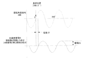
ここで、図2の上側の波形は、回転検出器11で得られる回転角度信号であり、下側の波形は、振動センサ12で得られる信号(ここでは加速度信号)である。振動データV(N)は、図2の下側に示すように、回転体7の周波数と同じ周波数成分をもつ振動の振幅Sと、回転体7の周波数と同じ周波数成分をもつ振動の回転角度の基準位置に対する位相(角度)θからなる情報であり、回転数Nごとに算出される。回転角度の基準位置は、例えば、回転角度信号(A相信号)の0°の位置である。
また、この振動データV(N)は計算上の理由からベクトル量で扱うのが都合がよいため、振幅Sを大きさ、位相θを偏角とした複素数として扱う。
Here, the upper waveform in FIG. 2 is a rotation angle signal obtained by the
Further, since it is convenient to handle the vibration data V (N) as a vector quantity for calculation reasons, the vibration data V (N) is handled as a complex number having the amplitude S as the magnitude and the phase θ as the argument.
影響係数Fは、回転体7のアンバランス量Uが振動Vに与える影響を示す伝達関数である。回転数毎の影響係数F(N)は、下記(1)〜(3)のようにして算出する。
The influence coefficient F is a transfer function indicating the influence of the unbalance amount U of the
(1)おもり無しでの振動データの計測
まず、アンバランス計測装置1のマウント4に、計測対象の回転機械6ではなく、回転機械6と同等に模擬された模擬体(図示せず)を取り付けて、模擬体の回転体を回転させ、回転数を増速、減速するなどして、広い回転数領域で回転数毎の振動データを取得する。このときの振動データを、
V0(N)=ar0(N)+j×ai0(N)・・・(1)
とする。Nは回転数である。
(1) Measurement of vibration data without weight First, not a
V0 (N) = ar0 (N) + j × ai0 (N) (1)
And N is the rotational speed.
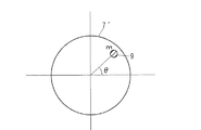
(2)おもり付加での振動データの計測
次に、図3に示すように、模擬体の回転体7´上の基準位置からθの位置に、重さmのおもり9を付加し、この状態で模擬体の回転体7´を回転させ、回転数を増速、減速するなどして、広い回転数範囲で回転数毎の振動データを取得する。このときの振動データを、
V1(N)=ar1(N)+j×ai1(N)・・・(2)
とする。
(2) Measurement of vibration data with addition of weight Next, as shown in FIG. 3, a
V1 (N) = ar1 (N) + j × ai1 (N) (2)
And
(3)影響係数の算出
上記(1)、(2)で取得した振動データから、下記(3)式により、広い回転数領域での影響係数F(N)を算出する。
影響係数F(N)={V1(N)−V0(N)}/{m(cosθ+jsinθ)}・・・(3)
(3) Calculation of influence coefficient From the vibration data acquired in the above (1) and (2), the influence coefficient F (N) in a wide rotation speed region is calculated by the following expression (3).
Influence coefficient F (N) = {V1 (N) −V0 (N)} / {m (cos θ + jsin θ)} (3)
影響係数F(N)を算出する回転数の範囲は、アンバランス計測をする回転数を考慮して決定される。例えば、特定の回転数(例えば5万rmp)でのみアンバランス計測を実施する場合には、その回転数の前後(例えばプラスマイナス1000rpm)の範囲で影響係数F(N)を算出する。また、広い範囲にわたる回転数(例えば1万〜10万rpm)で各回転数毎にアンバランス計測を実施する場合には、その範囲に対応した広い範囲で影響係数F(N)を算出する。 The range of the rotational speed for calculating the influence coefficient F (N) is determined in consideration of the rotational speed for performing unbalance measurement. For example, when unbalance measurement is performed only at a specific rotation speed (for example, 50,000 rpm), the influence coefficient F (N) is calculated in a range around that rotation speed (for example, plus or minus 1000 rpm). When unbalance measurement is performed for each rotation speed at a rotation speed over a wide range (for example, 10,000 to 100,000 rpm), the influence coefficient F (N) is calculated in a wide range corresponding to the range.
(4)アンバランス量の算出
演算器13は、以上のようにして回転数毎の影響係数F(N)を算出し、これを記憶しておく。そして、アンバランス計測装置1のマウント4に計測対象の回転機械6を取り付けて、回転体7をアンバランス計測のための特定の回転数で回転させ、振動データを取得する。このとき、回転体7の回転数は特定の回転数となるように制御されるが、実際には回転数の変動があるため、複数の回転数についてのデータが得られる。このときの振動データを、
V3(N)=ar3(N)+jai3(N)・・・(4)
とする。
(4) Calculation of Unbalance Amount The
V3 (N) = ar3 (N) + jai3 (N) (4)
And
回転数毎のアンバランス量U(N)は、次の(5)式で求めることができる。
U(N)=V3(N)/F(N)=A(N)+jB(N)・・・(5)
演算器13は、回転数毎のアンバランス量U(N)を算出し、得られた回転数毎のアンバランス量U(N)を平均化して、回転体7のアンバランス量Uを算出する。
The unbalance amount U (N) for each rotation speed can be obtained by the following equation (5).
U (N) = V3 (N) / F (N) = A (N) + jB (N) (5)
The
上記(5)の式では、回転数の関数になっているが、真のアンバランス量は回転数によって変動しないため、それぞれの回転数での値を平均化することで、1つの回転数での計測結果が悪かったとしても、それに大きく影響されずにアンバランス量を算出することができる。 In the above equation (5), although it is a function of the number of rotations, the true unbalance amount does not vary with the number of rotations, so by averaging the values at each number of rotations, Even if the measurement result is poor, the unbalance amount can be calculated without being greatly influenced by the measurement result.
A(N)+jB(N)を平均した値を、アンバランス量U=A+jB、とすると、
(アンバランス量の大きさ)=(A2+B2)1/2
(アンバランス角度)=tan−1(B/A)
として算出できる。
Assuming that the average value of A (N) + jB (N) is the unbalance amount U = A + jB,
(Size of unbalance amount) = (A 2 + B 2 ) 1/2
(Unbalance angle) = tan −1 (B / A)
Can be calculated as
上述したように、上記の本発明によれば、広い回転数領域で各回転数(N)に対応した影響係数F(N)を計測しておき、影響係数F(N)を使用してアンバランス量Uを算出する。これにより、アンバランス計測のための回転体7の回転運転時に回転数が安定しなくても、回転数に応じた影響係数F(N)を使用してアンバランス量Uを算出するので、精度よくアンバランス量を計測することができる。
As described above, according to the present invention, the influence coefficient F (N) corresponding to each rotation speed (N) is measured in a wide rotation speed region, and the influence coefficient F (N) is used to measure the influence coefficient F (N). The balance amount U is calculated. Thereby, even if the rotational speed is not stable during the rotational operation of the
ここで、演算器13は、回転数毎のアンバランス量U(N)を平均化する段階において、回転数毎のデータ数の頻度に基づいて各アンバランス量U(N)に重み付けを行って平均化するのがよい。
Here, the
例えば、下記[表1]のようなデータが得られたとする。
この場合、アンバランス量Uは、下記(6)式で算出することができる。Dsはデータ数の総和である。
U=(U1×D1+U2×D2+・・・Un×Dn)/Ds・・・(6)
For example, it is assumed that data as shown in [Table 1] below is obtained.
In this case, the unbalance amount U can be calculated by the following equation (6). Ds is the total number of data.
U = (U1 × D1 + U2 × D2 +... Un × Dn) / Ds (6)
このように、回転数毎のデータ数の頻度に基づいて各アンバランス量U(N)に重み付けを行って平均化するので、頻度の低い回転数の不安定なデータの影響が小さくなり、アンバランス量の算出精度を向上させることができる。 Thus, since each unbalance amount U (N) is weighted and averaged based on the frequency of the number of data for each number of rotations, the influence of unstable data at a low number of rotations is reduced and unbalanced. The calculation accuracy of the balance amount can be improved.
ここで、回転数毎のアンバランス量のデータにおいて、例えば、ある回転数pのアンバランス量がUp−1、Up−2、Up−3のように、同一回転数において異なるアンバランス量のデータが複数得られる場合がある。この場合、演算器13は、同一回転数についての複数のデータから代表的に選択した一つのデータ(例えばUp−1)、あるいは当該複数のデータのうちの一部または全部の平均値を、当該回転数におけるアンバランス量U(N)とするのがよい。これにより、計算に用いるデータを適正化するので、アンバランス量の算出精度を向上させることができる。
Here, in the unbalance amount data for each rotation speed, for example, the unbalance amount data for a certain rotation speed p is different in the same rotation speed such as Up-1, Up-2, and Up-3. May be obtained multiple times. In this case, the
なお、上記において、本発明の実施形態について説明を行ったが、上記に開示された本発明の実施の形態は、あくまで例示であって、本発明の範囲はこれら発明の実施の形態に限定されない。本発明の範囲は、特許請求の範囲の記載によって示され、さらに特許請求の範囲の記載と均等の意味および範囲内でのすべての変更を含むものである。 Although the embodiments of the present invention have been described above, the embodiments of the present invention disclosed above are merely examples, and the scope of the present invention is not limited to these embodiments. . The scope of the present invention is indicated by the description of the scope of claims, and further includes meanings equivalent to the description of the scope of claims and all modifications within the scope.
1 アンバランス計測装置
2 ベース
3 バネ部材
4 マウント
6 回転機械
7 回転体
8 軸
9 おもり
10 アンバランス量算出装置
11 回転検出器
12 振動センサ
DESCRIPTION OF SYMBOLS 1
Claims (6)
所定範囲の回転数領域で回転数毎に影響係数F(N)を求め、
回転する回転体の回転角度及び振動を検出して回転数毎の振動データV(N)を算出し、
回転数毎の振動データV(N)と、それぞれの回転数に対応した影響係数F(N)とに基づいて、回転数毎のアンバランス量U(N)を算出し、
得られた回転数毎のアンバランス量U(N)を平均化して、回転体のアンバランス量Uを算出する、ことを特徴とする回転体のアンバランス量算出方法:
ここで、前記振動データV(N)は、回転数の周波数と同じ周波数成分をもつ振動の振幅Sと、回転体の周波数と同じ周波数成分をもつ振動の、回転角度の基準位置に対する位相θからなる情報であり、回転数Nごとに算出される。 A rotating body unbalance amount calculating method for calculating the unbalance amount of the rotating body based on vibration data of the rotating body and an influence coefficient indicating an influence of the unbalance amount of the rotating body on the vibration,
An influence coefficient F (N) is obtained for each rotation speed within a predetermined range of rotation speed,
Detecting the rotation angle and vibration of the rotating rotating body to calculate vibration data V (N) for each rotation speed,
Based on the vibration data V (N) for each rotation speed and the influence coefficient F (N) corresponding to each rotation speed, an unbalance amount U (N) for each rotation speed is calculated,
An unbalance amount U (N) for each rotation speed obtained is averaged to calculate the unbalance amount U of the rotator.
Here, the vibration data V (N) is derived from the amplitude S of the vibration having the same frequency component as the frequency of the rotation speed and the phase θ of the vibration having the same frequency component as the frequency of the rotating body with respect to the reference position of the rotation angle. And is calculated for each rotation speed N.
回転する回転体の回転角度及び振動を検出するデータ検出手段と、
回転体のアンバランス量Uを算出する演算器とを備え、
前記演算器は、データ検出手段からの検出データに基づいて回転数毎の振動データV(N)を算出し、回転数毎の振動データV(N)と、それぞれの回転数に対応した影響係数F(N)とに基づいて、回転数毎のアンバランス量U(N)を算出し、得られた回転数毎のアンバランス量U(N)を平均化して、回転体のアンバランス量Uを算出する、ことを特徴とする回転体のアンバランス量算出装置:
ここで、前記振動データV(N)は、回転数の周波数と同じ周波数成分をもつ振動の振幅Sと、回転体の周波数と同じ周波数成分をもつ振動の、回転角度の基準位置に対する位相θからなる情報であり、回転数Nごとに算出される。 A rotating body unbalance amount calculating device for calculating the unbalance amount of the rotating body based on vibration data of the rotating body and an influence coefficient indicating an influence of the unbalance amount of the rotating body on vibrations,
Data detection means for detecting the rotation angle and vibration of the rotating rotating body;
A calculator for calculating the unbalance amount U of the rotating body,
The computing unit calculates vibration data V (N) for each rotation speed based on the detection data from the data detection means, and the vibration data V (N) for each rotation speed and the influence coefficient corresponding to each rotation speed. Based on F (N), an unbalance amount U (N) for each rotational speed is calculated, and the obtained unbalance amount U (N) for each rotational speed is averaged to obtain an unbalance amount U of the rotating body. An unbalance amount calculation device for a rotating body, characterized in that:
Here, the vibration data V (N) is derived from the amplitude S of the vibration having the same frequency component as the frequency of the rotation speed and the phase θ of the vibration having the same frequency component as the frequency of the rotating body with respect to the reference position of the rotation angle. And is calculated for each rotation speed N.
Priority Applications (1)
| Application Number | Priority Date | Filing Date | Title |
|---|---|---|---|
| JP2008211303A JP5418805B2 (en) | 2008-08-20 | 2008-08-20 | Method and apparatus for calculating unbalance amount of rotating body |
Applications Claiming Priority (1)
| Application Number | Priority Date | Filing Date | Title |
|---|---|---|---|
| JP2008211303A JP5418805B2 (en) | 2008-08-20 | 2008-08-20 | Method and apparatus for calculating unbalance amount of rotating body |
Publications (2)
| Publication Number | Publication Date |
|---|---|
| JP2010048588A true JP2010048588A (en) | 2010-03-04 |
| JP5418805B2 JP5418805B2 (en) | 2014-02-19 |
Family
ID=42065798
Family Applications (1)
| Application Number | Title | Priority Date | Filing Date |
|---|---|---|---|
| JP2008211303A Active JP5418805B2 (en) | 2008-08-20 | 2008-08-20 | Method and apparatus for calculating unbalance amount of rotating body |
Country Status (1)
| Country | Link |
|---|---|
| JP (1) | JP5418805B2 (en) |
Cited By (7)
| Publication number | Priority date | Publication date | Assignee | Title |
|---|---|---|---|---|
| JP2012002615A (en) * | 2010-06-16 | 2012-01-05 | Ihi Corp | Unbalance amount measuring method and device therefor |
| JP2012013596A (en) * | 2010-07-02 | 2012-01-19 | Ihi Corp | Rotor and balance correction method for the same |
| JP2012037409A (en) * | 2010-08-09 | 2012-02-23 | Ihi Corp | Balance correction device and method |
| JP2013044583A (en) * | 2011-08-23 | 2013-03-04 | Ihi Corp | Rotation angle detection device and method |
| KR20150076019A (en) * | 2013-12-26 | 2015-07-06 | 현대제철 주식회사 | Method for monitoring condition of impeller and apparatus thereof |
| CN112729682A (en) * | 2020-12-24 | 2021-04-30 | 厦门大学 | Method for obtaining equivalent unbalance amount of rotor and method for improving critical rotating speed vibration response of rotor |
| CN114429000A (en) * | 2022-04-06 | 2022-05-03 | 江铃汽车股份有限公司 | Method, system and equipment for predicting dynamic unbalance finished automobile response of transmission system |
Families Citing this family (1)
| Publication number | Priority date | Publication date | Assignee | Title |
|---|---|---|---|---|
| CN109724749A (en) * | 2018-12-26 | 2019-05-07 | 河钢股份有限公司承德分公司 | The calculation method of Hysteresis phase lag is sought in Dynamic Balance of Rotor experiment |
Citations (4)
| Publication number | Priority date | Publication date | Assignee | Title |
|---|---|---|---|---|
| JP2002350271A (en) * | 2001-03-27 | 2002-12-04 | Goodyear Tire & Rubber Co:The | Tire uniformity prediction using balance and low-speed uniformity data |
| JP2004020383A (en) * | 2002-06-17 | 2004-01-22 | Denso Corp | Method for correcting work rotation speed dependency characteristic in balancing machine |
| JP2004271484A (en) * | 2003-03-12 | 2004-09-30 | Akashi Corp | Rotation test device |
| JP2008102049A (en) * | 2006-10-20 | 2008-05-01 | Hitachi Ltd | Balance correction device |
-
2008
- 2008-08-20 JP JP2008211303A patent/JP5418805B2/en active Active
Patent Citations (4)
| Publication number | Priority date | Publication date | Assignee | Title |
|---|---|---|---|---|
| JP2002350271A (en) * | 2001-03-27 | 2002-12-04 | Goodyear Tire & Rubber Co:The | Tire uniformity prediction using balance and low-speed uniformity data |
| JP2004020383A (en) * | 2002-06-17 | 2004-01-22 | Denso Corp | Method for correcting work rotation speed dependency characteristic in balancing machine |
| JP2004271484A (en) * | 2003-03-12 | 2004-09-30 | Akashi Corp | Rotation test device |
| JP2008102049A (en) * | 2006-10-20 | 2008-05-01 | Hitachi Ltd | Balance correction device |
Cited By (9)
| Publication number | Priority date | Publication date | Assignee | Title |
|---|---|---|---|---|
| JP2012002615A (en) * | 2010-06-16 | 2012-01-05 | Ihi Corp | Unbalance amount measuring method and device therefor |
| JP2012013596A (en) * | 2010-07-02 | 2012-01-19 | Ihi Corp | Rotor and balance correction method for the same |
| JP2012037409A (en) * | 2010-08-09 | 2012-02-23 | Ihi Corp | Balance correction device and method |
| JP2013044583A (en) * | 2011-08-23 | 2013-03-04 | Ihi Corp | Rotation angle detection device and method |
| KR20150076019A (en) * | 2013-12-26 | 2015-07-06 | 현대제철 주식회사 | Method for monitoring condition of impeller and apparatus thereof |
| KR101581512B1 (en) | 2013-12-26 | 2015-12-30 | 현대제철 주식회사 | Method for monitoring condition of impeller and apparatus thereof |
| CN112729682A (en) * | 2020-12-24 | 2021-04-30 | 厦门大学 | Method for obtaining equivalent unbalance amount of rotor and method for improving critical rotating speed vibration response of rotor |
| CN114429000A (en) * | 2022-04-06 | 2022-05-03 | 江铃汽车股份有限公司 | Method, system and equipment for predicting dynamic unbalance finished automobile response of transmission system |
| CN114429000B (en) * | 2022-04-06 | 2022-07-08 | 江铃汽车股份有限公司 | Method, system and equipment for predicting dynamic unbalance finished automobile response of transmission system |
Also Published As
| Publication number | Publication date |
|---|---|
| JP5418805B2 (en) | 2014-02-19 |
Similar Documents
| Publication | Publication Date | Title |
|---|---|---|
| JP5418805B2 (en) | Method and apparatus for calculating unbalance amount of rotating body | |
| JP5288320B2 (en) | Apparatus and method for measuring rotational balance of high-speed rotating body | |
| US10823632B2 (en) | Method for measuring the unbalance of flexible rotors by means of position-measuring sensors | |
| US7272513B2 (en) | Optimal shaft balance using integer programing to handle discrete adjustment | |
| JP5521951B2 (en) | Rotating body unbalance correction method and unbalance correction amount calculation device | |
| CN110006590B (en) | Method for obtaining unbalance amount of rotor and unbalance amount of balancing machine | |
| US20150185107A1 (en) | Method and device for balancing ct gantry | |
| CN105092255B (en) | Fanjet fan complete machine Calculate Ways and system | |
| CN103115726A (en) | Rotating parts and components dynamic balance method based on strain | |
| JP2009236880A (en) | Standard exciter | |
| JP5428550B2 (en) | How to obtain influence coefficient | |
| JP5170837B2 (en) | Rotation angle detection method and apparatus | |
| JP2005308537A (en) | Balance analyzer and balance analysis method by the same | |
| JP5553215B2 (en) | Method and apparatus for measuring unbalance amount | |
| JP4098429B2 (en) | Balance test machine and balance test method | |
| JP5257762B2 (en) | Apparatus and method for measuring rotational balance of high-speed rotating body | |
| JP5622178B2 (en) | How to obtain influence coefficient | |
| JP2002214034A (en) | Device and method for computing and confirming vibration level of high-speed rotary equipment | |
| JP2005308538A (en) | Balance testing machine and correction weight calculating/processing method by the same | |
| US6408675B1 (en) | Eccentric error corrector and method of eccentric error correction for acceleration sensor in acceleration generating apparatus | |
| JP5459533B2 (en) | Unbalance measurement method and apparatus | |
| JP5418830B2 (en) | Trial weight mounting orientation calculation device and method | |
| JP4078193B2 (en) | Balance measuring machine and balance adjusting machine | |
| JP5645066B2 (en) | Influence coefficient acquisition method and device | |
| JPH04315936A (en) | Unbalance amount measurement device for rotating body |
Legal Events
| Date | Code | Title | Description |
|---|---|---|---|
| A621 | Written request for application examination |
Free format text: JAPANESE INTERMEDIATE CODE: A621 Effective date: 20110627 |
|
| A131 | Notification of reasons for refusal |
Free format text: JAPANESE INTERMEDIATE CODE: A131 Effective date: 20130716 |
|
| A521 | Written amendment |
Free format text: JAPANESE INTERMEDIATE CODE: A523 Effective date: 20130822 |
|
| TRDD | Decision of grant or rejection written | ||
| A01 | Written decision to grant a patent or to grant a registration (utility model) |
Free format text: JAPANESE INTERMEDIATE CODE: A01 Effective date: 20131024 |
|
| A61 | First payment of annual fees (during grant procedure) |
Free format text: JAPANESE INTERMEDIATE CODE: A61 Effective date: 20131106 |
|
| R151 | Written notification of patent or utility model registration |
Ref document number: 5418805 Country of ref document: JP Free format text: JAPANESE INTERMEDIATE CODE: R151 |
|
| R250 | Receipt of annual fees |
Free format text: JAPANESE INTERMEDIATE CODE: R250 |
|
| R250 | Receipt of annual fees |
Free format text: JAPANESE INTERMEDIATE CODE: R250 |