JP2010048307A - ホース端部への継手部材の取付方法及びその装置 - Google Patents
ホース端部への継手部材の取付方法及びその装置 Download PDFInfo
- Publication number
- JP2010048307A JP2010048307A JP2008211793A JP2008211793A JP2010048307A JP 2010048307 A JP2010048307 A JP 2010048307A JP 2008211793 A JP2008211793 A JP 2008211793A JP 2008211793 A JP2008211793 A JP 2008211793A JP 2010048307 A JP2010048307 A JP 2010048307A
- Authority
- JP
- Japan
- Prior art keywords
- diameter
- hose
- socket
- caulking
- joint member
- Prior art date
- Legal status (The legal status is an assumption and is not a legal conclusion. Google has not performed a legal analysis and makes no representation as to the accuracy of the status listed.)
- Granted
Links
- 238000000034 method Methods 0.000 title claims abstract description 23
- 230000002093 peripheral effect Effects 0.000 claims abstract description 29
- 210000000078 claw Anatomy 0.000 claims description 45
- 238000002788 crimping Methods 0.000 claims description 37
- 238000005259 measurement Methods 0.000 claims description 22
- 238000003384 imaging method Methods 0.000 claims description 21
- 239000002184 metal Substances 0.000 claims description 7
- 238000003860 storage Methods 0.000 claims description 6
- 230000008878 coupling Effects 0.000 claims description 2
- 238000010168 coupling process Methods 0.000 claims description 2
- 238000005859 coupling reaction Methods 0.000 claims description 2
- 230000000087 stabilizing effect Effects 0.000 abstract 1
- 238000001514 detection method Methods 0.000 description 18
- 230000000694 effects Effects 0.000 description 5
- 238000010586 diagram Methods 0.000 description 3
- 239000007769 metal material Substances 0.000 description 3
- 210000002445 nipple Anatomy 0.000 description 3
- 230000003014 reinforcing effect Effects 0.000 description 3
- 210000000569 greater omentum Anatomy 0.000 description 1
- 238000007689 inspection Methods 0.000 description 1
- 230000001678 irradiating effect Effects 0.000 description 1
- 239000004973 liquid crystal related substance Substances 0.000 description 1
- 238000004519 manufacturing process Methods 0.000 description 1
- 239000000463 material Substances 0.000 description 1
- 238000003908 quality control method Methods 0.000 description 1
Images


Landscapes
- Joints That Cut Off Fluids, And Hose Joints (AREA)
Abstract
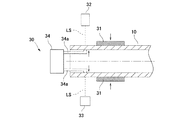
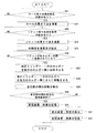
【解決手段】この継手部材の取付装置は、内側嵌合部21aにホース10の端部の内周面を嵌合させる前にホース10の端部の内径及び外径を測定し、その測定結果に基づき、ソケット22と内側嵌合部21aとの間に配置されているホース10の締付け率が所望の締付け率(本実施形態では45%)になるように、ソケット22の加締径Dが設定され、その設定された加締径Dまでソケット22が加締められる。このため、ホース10の径寸法のばらつきに拘わらずにホース10の締付け率が安定する。
【選択図】図8
Description
Claims (10)
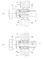
- ホース端部の内周面に嵌合可能な円筒状の内側嵌合部とその径方向外側に配置されてホース端部の外径よりも大きい内径を有する金属製のソケットとを備えた継手部材の内側嵌合部にホース端部の内周面を嵌合させる嵌合工程と、周方向に並設された複数の加締爪によってソケットを径方向内側に向かって加締めてソケットと内側嵌合部の間に配置されているホースを締付けることによりホース端部に継手部材を取付ける加締工程とを含むホース端部への継手部材の取付方法において、
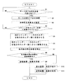
前記内側嵌合部にホース端部の内周面を嵌合させる前にホース端部の内径及び外径を測定するホース径寸法測定工程と、
ホース径寸法測定工程の測定結果に基づき、ソケットと内側嵌合部の間に配置されているホースが所望の締付け率で締付けられるように、加締工程におけるソケットの加締径を設定する加締径設定工程とを含み、
前記加締工程を、加締径設定工程によって設定された加締径までソケットを加締めるように構成した
ことを特徴とするホース端部への継手部材の取付方法。 - 前記内側嵌合部にホース端部の内周面を嵌合させる前にソケットの内径及び外径を測定するソケット径寸法測定工程を含み、
前記加締径設定工程を、ホース径寸法測定工程及びソケット径寸法測定工程の測定結果に基づき、ソケットと内側嵌合部の間に配置されているホースが所望の締付け率で締付けられるように、加締工程におけるソケットの加締径を設定するように構成した
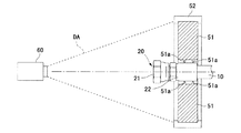
ことを特徴とする請求項1に記載のホース端部への継手部材の取付方法。 - 前記各加締爪によってソケットを加締径まで加締めた際に、各加締爪の所定位置にそれぞれ設けられたマーク部を画角内に入るように撮像する撮像工程と、
撮像工程による撮像データに基づいて各マーク部間の距離を測定する距離測定工程とを含む
ことを特徴とする請求項1または2の何れかに記載のホース端部への継手部材の取付方法。 - 前記距離測定工程による各マーク部間の距離が規格範囲内か否かを判定する判定工程を含む
ことを特徴とする請求項3に記載のホース端部への継手部材の取付方法。 - 前記判定工程による判定結果を記憶する記憶工程を含む
ことを特徴とする請求項4に記載のホース端部への継手部材の取付方法。 - ホース端部の内周面に嵌合可能な円筒状の内側嵌合部とその径方向外側に配置されてホース端部の外径よりも大きい内径を有する金属製のソケットとを備えた継手部材の内側嵌合部にホース端部の内周面が嵌合している状態で、周方向に並設された複数の加締爪によってソケットを径方向内側に向かって加締める加締装置を備え、加締装置によってソケットを加締めてソケットと内側嵌合部の間に配置されているホースを締付けることにより、ホース端部に継手部材を取付けるホース端部への継手部材の取付装置において、
前記内側嵌合部にホース端部の内周面を嵌合させる前にホース端部の内径及び外径を測定するホース径寸法測定手段と、
ホース径寸法測定手段の測定結果に基づき、ソケットと内側嵌合部との間に配置されているホースが所望の締付け率で締付けられるように、加締装置によるソケットの加締径を設定する加締径設定手段とを備え、
前記加締装置を、加締径設定手段によって設定された加締径までソケットを加締めるように構成した
ことを特徴とするホース端部への継手部材の取付装置。 - 前記内側嵌合部にホース端部の内周面を嵌合させる前にソケットの内径及び外径を測定するソケット径寸法測定手段を備え、
前記加締径設定手段を、ホース径寸法測定手段及びソケット径寸法測定手段の測定結果に基づき、ソケットと内側嵌合部の間に配置されているホースが所望の締付け率で締付けられるように、加締装置によるソケットの加締径を設定するように構成した
ことを特徴とする請求項6に記載のホース端部への継手部材の取付装置。 - 前記各加締爪の所定位置にそれぞれ設けられたマーク部と、
各加締爪によってソケットを加締径まで加締めた際に各マーク部を画角内に入るように撮像する撮像装置と、
撮像装置による撮像データに基づいて各マーク部間の距離を測定する距離測定手段とを備えた
ことを特徴とする請求項6または7の何れかに記載のホース端部への継手部材の取付装置。 - 前記距離測定手段による各マーク部間の距離が規格範囲内か否かを判定する判定手段を備えた
ことを特徴とする請求項8に記載のホース端部への継手部材の取付装置。 - 前記判定手段による判定結果を記憶する記憶手段を備えた
ことを特徴とする請求項9に記載のホース端部への継手部材の取付装置。
Priority Applications (1)
| Application Number | Priority Date | Filing Date | Title |
|---|---|---|---|
| JP2008211793A JP5229463B2 (ja) | 2008-08-20 | 2008-08-20 | ホース端部への継手部材の取付方法及びその装置 |
Applications Claiming Priority (1)
| Application Number | Priority Date | Filing Date | Title |
|---|---|---|---|
| JP2008211793A JP5229463B2 (ja) | 2008-08-20 | 2008-08-20 | ホース端部への継手部材の取付方法及びその装置 |
Publications (2)
| Publication Number | Publication Date |
|---|---|
| JP2010048307A true JP2010048307A (ja) | 2010-03-04 |
| JP5229463B2 JP5229463B2 (ja) | 2013-07-03 |
Family
ID=42065561
Family Applications (1)
| Application Number | Title | Priority Date | Filing Date |
|---|---|---|---|
| JP2008211793A Expired - Fee Related JP5229463B2 (ja) | 2008-08-20 | 2008-08-20 | ホース端部への継手部材の取付方法及びその装置 |
Country Status (1)
| Country | Link |
|---|---|
| JP (1) | JP5229463B2 (ja) |
Cited By (2)
| Publication number | Priority date | Publication date | Assignee | Title |
|---|---|---|---|---|
| CN109405700A (zh) * | 2018-12-18 | 2019-03-01 | 东风商用车有限公司 | 一种金属软管安装姿态的检测用具及使用方法 |
| WO2019049717A1 (ja) * | 2017-09-11 | 2019-03-14 | 横浜ゴム株式会社 | ホース継手金具の形状測定装置、ホース継手金具の形状測定方法およびホース継手金具の形状測定プログラム |
Citations (3)
| Publication number | Priority date | Publication date | Assignee | Title |
|---|---|---|---|---|
| JPS62251032A (ja) * | 1986-04-22 | 1987-10-31 | Kawasaki Steel Corp | テ−パねじカツプリングの締付方法および装置 |
| JPH0771672A (ja) * | 1990-01-30 | 1995-03-17 | Hans Oetiker Ag Mas & Apparatefab | 高圧継手およびその取付け装置 |
| JPH08132324A (ja) * | 1994-11-08 | 1996-05-28 | Nissan Motor Co Ltd | ホースクランプ自動組み付け装置 |
-
2008
- 2008-08-20 JP JP2008211793A patent/JP5229463B2/ja not_active Expired - Fee Related
Patent Citations (3)
| Publication number | Priority date | Publication date | Assignee | Title |
|---|---|---|---|---|
| JPS62251032A (ja) * | 1986-04-22 | 1987-10-31 | Kawasaki Steel Corp | テ−パねじカツプリングの締付方法および装置 |
| JPH0771672A (ja) * | 1990-01-30 | 1995-03-17 | Hans Oetiker Ag Mas & Apparatefab | 高圧継手およびその取付け装置 |
| JPH08132324A (ja) * | 1994-11-08 | 1996-05-28 | Nissan Motor Co Ltd | ホースクランプ自動組み付け装置 |
Cited By (4)
| Publication number | Priority date | Publication date | Assignee | Title |
|---|---|---|---|---|
| WO2019049717A1 (ja) * | 2017-09-11 | 2019-03-14 | 横浜ゴム株式会社 | ホース継手金具の形状測定装置、ホース継手金具の形状測定方法およびホース継手金具の形状測定プログラム |
| US11162780B2 (en) | 2017-09-11 | 2021-11-02 | The Yokohama Rubber Co., Ltd. | Shape measuring device for hose connector fitting, shape measuring method for hose connector fitting and shape measuring program for hose connector fitting |
| CN109405700A (zh) * | 2018-12-18 | 2019-03-01 | 东风商用车有限公司 | 一种金属软管安装姿态的检测用具及使用方法 |
| CN109405700B (zh) * | 2018-12-18 | 2024-03-22 | 东风商用车有限公司 | 一种金属软管安装姿态的检测用具及使用方法 |
Also Published As
| Publication number | Publication date |
|---|---|
| JP5229463B2 (ja) | 2013-07-03 |
Similar Documents
| Publication | Publication Date | Title |
|---|---|---|
| CN103080693B (zh) | 轮胎外形测量数据校正方法和轮胎外观检查装置 | |
| US10308464B2 (en) | Apparatus and method for determining a distance measure on wound-up materials | |
| EP3171128B1 (en) | Method for correcting surface shape data of an annular rotating object, and device for inspecting appearance of an annular rotating object | |
| US10113867B2 (en) | Device and method for three-dimensional reconstruction of a scene by image analysis | |
| EP1596218A3 (en) | Information processing method and system | |
| WO2014163921A1 (en) | Laser videogrammetry | |
| US10076885B2 (en) | Joining state determination method and molding device | |
| JP2009524238A5 (ja) | ||
| JP5923054B2 (ja) | 形状検査装置 | |
| JP5229463B2 (ja) | ホース端部への継手部材の取付方法及びその装置 | |
| US20180051983A1 (en) | Measurement system and method for configuring the measurement system | |
| JP2004062757A5 (ja) | ||
| JP2007281003A5 (ja) | ||
| JP6521700B2 (ja) | 計測装置および計測方法 | |
| JP2015148783A5 (ja) | 焦点調節装置および制御方法 | |
| US20200284670A1 (en) | Gear positioning device, stress measurement system, gear positioning method, and stress measurement method | |
| JP6040770B2 (ja) | タイヤ解析システムおよび解析方法 | |
| JP2009288108A (ja) | 画像相関変位計 | |
| JP2004511793A (ja) | シリンダ状部材の基準方向に対する整列を判定するための方法 | |
| CN102410813B (zh) | 电机跳动检测装置及检测方法 | |
| JP6441273B2 (ja) | バルブ隙間測定装置 | |
| WO2020059685A1 (ja) | センサシステム、および、傾き検出方法 | |
| KR101620970B1 (ko) | 피스톤 장착 기반의 피스톤 링 합구틈새 검사 장치, 그리고 이를 이용한 피스톤 링 합구틈새 측정 방법 | |
| KR101500221B1 (ko) | 주조롤의 슬롯 가공 장치 및 방법 | |
| Ettl et al. | “Flying triangulation”: a motion-robust optical 3D sensor principle |
Legal Events
| Date | Code | Title | Description |
|---|---|---|---|
| A621 | Written request for application examination |
Free format text: JAPANESE INTERMEDIATE CODE: A621 Effective date: 20110811 |
|
| TRDD | Decision of grant or rejection written | ||
| A01 | Written decision to grant a patent or to grant a registration (utility model) |
Free format text: JAPANESE INTERMEDIATE CODE: A01 Effective date: 20130220 |
|
| A61 | First payment of annual fees (during grant procedure) |
Free format text: JAPANESE INTERMEDIATE CODE: A61 Effective date: 20130305 |
|
| FPAY | Renewal fee payment (event date is renewal date of database) |
Free format text: PAYMENT UNTIL: 20160329 Year of fee payment: 3 |
|
| R150 | Certificate of patent or registration of utility model |
Ref document number: 5229463 Country of ref document: JP Free format text: JAPANESE INTERMEDIATE CODE: R150 Free format text: JAPANESE INTERMEDIATE CODE: R150 |
|
| R250 | Receipt of annual fees |
Free format text: JAPANESE INTERMEDIATE CODE: R250 |
|
| R250 | Receipt of annual fees |
Free format text: JAPANESE INTERMEDIATE CODE: R250 |
|
| R250 | Receipt of annual fees |
Free format text: JAPANESE INTERMEDIATE CODE: R250 |
|
| LAPS | Cancellation because of no payment of annual fees |