JP2010045295A - Original point positioning control method for electric component feeder in component mounting device - Google Patents
Original point positioning control method for electric component feeder in component mounting device Download PDFInfo
- Publication number
- JP2010045295A JP2010045295A JP2008209787A JP2008209787A JP2010045295A JP 2010045295 A JP2010045295 A JP 2010045295A JP 2008209787 A JP2008209787 A JP 2008209787A JP 2008209787 A JP2008209787 A JP 2008209787A JP 2010045295 A JP2010045295 A JP 2010045295A
- Authority
- JP
- Japan
- Prior art keywords
- component mounting
- mounting apparatus
- component
- electric component
- origin
- Prior art date
- Legal status (The legal status is an assumption and is not a legal conclusion. Google has not performed a legal analysis and makes no representation as to the accuracy of the status listed.)
- Granted
Links
Images


Abstract
Description
本発明は、部品実装装置における電動式部品供給装置の原点位置合わせ制御方法に関し、詳しくは、取り付けられた多数の電動式部品供給装置について部品ピックアップ位置の原点位置合わせを行うに際して、部品実装装置の必要最大電力の低減を可能とする部品実装装置における電動式部品供給装置の原点位置合わせ制御方法に関する。 The present invention relates to an origin position alignment control method for an electric component supply device in a component mounting apparatus. More specifically, the present invention relates to a method for adjusting the origin position of a component pickup position for a plurality of attached electric component supply devices. The present invention relates to an origin position alignment control method for an electric component supply apparatus in a component mounting apparatus that can reduce the required maximum power.
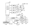
図6は、電子部品実装装置の概略図であり、同図に示すように、電子部品実装装置201は、中央部から少し後方で左右方向に延在する回路基板搬送路215と、装置201の前部(図示の下側)に配設され、回路基板210に実装される部品を供給する部品供給部211と、装置201の前部に配設されたX軸移動機構212とY軸移動機構214を備えている。
FIG. 6 is a schematic diagram of the electronic component mounting apparatus. As shown in FIG. 6, the electronic
X軸移動機構212は、部品を吸着する吸着ノズル213aを備えた吸着ヘッド部213をX軸方向に移動させ、またY軸移動機構214は、X軸移動機構212並びに吸着ヘッド部213をY軸方向に移動させる。また装着ヘッド部213は、吸着ノズル213aを垂直方向(Z軸方向)に昇降可能に移動させるZ軸移動機構を備え、また吸着ノズルをノズル軸(吸着軸)を中心に回転させるθ軸移動機構を備えている。また、吸着ヘッド部213には、支持部材に取り付けるようにして、回路基板210上に形成された基板マークを撮像する基板認識カメラ217が搭載されている。また、部品供給部211の側部には、吸着ノズル213aに吸着された部品を下方から撮像する部品認識カメラ(撮像手段)216が配置されている。
The
図7は、電子部品実装装置の制御系の構成を示している。220は、装置全体を制御するマイクロコンピュータ(CPU)、並びにRAM、ROMなどからなるコントローラ(制御手段)であり、これに以下の221〜231の構成が接続され、それぞれを制御している。
FIG. 7 shows the configuration of the control system of the electronic component mounting apparatus.
X軸モータ221は、X軸移動機構212の駆動源で、吸着ヘッド部213をX軸方向に移動させ、また、Y軸モータ222は、Y軸移動機構214の駆動源で、Y軸移動機構214をY軸方向に駆動し、それにより吸着ヘッド部213はX軸方向とY軸方向に移動可能となる。
The
Z軸モータ223は、吸着ノズル213aを昇降させるZ軸駆動機構(不図示)の駆動源で、吸着ノズル213aをZ軸方向(高さ方向)に昇降させる。また、θ軸モータ224は、吸着ノズル213aのθ軸回転機構(不図示)の駆動源で、吸着ノズル213aをそのノズル中心軸(吸着軸)を中心にして回転させる。
The Z-
画像認識装置227は、吸着ノズル213aに吸着された部品218の画像認識を行うもので、A/D変換器227a、メモリ227b及びCPU227cから構成される。そして、吸着された部品218を撮像した部品認識カメラ216から出力されるアナログの画像信号をA/D変換器227aによりデジタル信号に変換してメモリ227bに格納し、CPU227cがその画像データに基づいて吸着された部品の認識を行う。すなわち、画像認識装置227は、部品中心と吸着角度を演算し、部品の吸着姿勢を認識する。また、画像認識装置227は、基板認識カメラ217で撮像された基板マークの画像を処理して基板マーク位置を演算する。
The image recognition device 227 performs image recognition of the
また、画像認識装置227は、部品認識カメラ216で撮像された部品218の画像データと基板認識カメラ217で撮像された基板マークデータを処理して、両方の補正データを制御手段220へ転送する。
Further, the image recognition device 227 processes the image data of the
キーボード228とマウス229は、部品データなどのデータを入力するために用いられる。
The
記憶装置230は、フラッシュメモリなどで構成され、キーボード228とマウス229により入力された部品データ、及び不図示のホストコンピュータから供給される部品データなどを格納するのに用いられる。
The
表示装置(モニタ)231は、部品データ、演算データ、及び部品認識カメラ216で撮像した部品218の画像などをその表示面231aに表示する。
The display device (monitor) 231 displays component data, calculation data, an image of the
実際に、基板の生産を開始し、部品を回路基板に搭載する段階では、予め基板認識カメラ217で撮像された基板マークによる回路基板210の基板補正データ(Δx、Δy、Δθ)は記憶装置230に格納されている。そして、部品供給装置211から供給される部品を吸着ノズル213aで吸着し、吸着ヘッド部213を部品認識カメラ216上部に移動させて、部品を同カメラで撮像する。撮像された部品の画像は、画像認識装置227で画像処理され補正データを制御手段220へ転送する。制御手段220は記憶装置230から基板補正データと当該部品の部品データを読み出して、この部品データと前記転送された画像認識装置227で演算された部品中心と部品の傾きをもとに、部品の搭載位置と吸着姿勢を認識する。続いて、部品搭載位置の部品中心と吸着中心との間の水平方向位置ずれや部品の向きについての角度ずれが検出されると、これら水平方向位置ずれや角度ずれがX軸モータ221、Y軸モータ222、θ軸モータ224を駆動することにより、補正され、部品が所定の回路基板位置に正しい姿勢(基準角度)で搭載される。
Actually, at the stage where the production of the board is started and the parts are mounted on the circuit board, the board correction data (Δx, Δy, Δθ) of the
以上、電子部品実装装置について説明したが、この分野においても、他の機械装置分野と同様、コスト低減への取り組みがなされている。 The electronic component mounting apparatus has been described above. In this field as well, as in the other machine field, efforts are being made to reduce costs.
例えば、特許文献1には、図6(特許文献1の図1)に示すように、電源の接続および遮断を適切に制御して、消費電力量を削減する技術が提案されている。この技術は、具体的には、部品供給装置101A、101Bを駆動する部品供給駆動部107A、107B、部品移載装置102を駆動する部品移載駆動装置108、基板位置決め装置103を駆動する基板位置決め駆動装置109の各々に対し制御装置104からの指令により動力用電源と制御用電源を別々に接続、遮断できるようにしている。このため、部品実装装置100の構成各部が個々に停止する条件発生を制御装置104が検知したとき、制御装置104は、停止中の駆動装置への動力用電源を遮断することができる。これにより、部品実装装置100は、無駄な電力消費がなくなり必要最小限の電力で生産稼動を継続することができる。
For example, as shown in FIG. 6 (FIG. 1 of Patent Document 1),
ここで、部品供給装置として良く用いられている電動式テープフィーダは、その駆動に際しては比較的大きな電力を必要とするが、特許文献1に示された部品実装装置100では、前述のように、使用していない部品供給装置への電源を遮断することができ、無駄な電力消費がなくなり必要最小限の電力で生産稼動を継続することができる。
Here, the electric tape feeder that is often used as a component supply device requires relatively large electric power for driving, but the
しかしながら、一般的に部品実装装置においては、部品実装を開始する前に、取り付けられた電動式テープフィーダの部品ピックアップ位置の原点位置合わせを行う必要がある。この原点位置合わせの動作は、例えば部品実装装置の電源投入時等に、該部品実装装置に取り付けられている全ての電動式テープフィーダについて同時に行われるため、部品実装装置の必要最大電力は、該部品実装装置に取り付けられた電動式テープフィーダの全てを同時に駆動させるために必要な電力となってしまい、大きくなってしまっていた。このため、部品実装装置のために用意する電源の容量を大きくすることが必要となり、コストアップにつながっていた。 However, in general, in the component mounting apparatus, it is necessary to align the origin of the component pickup position of the attached electric tape feeder before starting the component mounting. This origin alignment operation is performed simultaneously for all the electric tape feeders attached to the component mounting apparatus, for example, when the component mounting apparatus is turned on. The electric power required to drive all the electric tape feeders attached to the component mounting apparatus at the same time has become large. For this reason, it is necessary to increase the capacity of the power supply prepared for the component mounting apparatus, leading to an increase in cost.
本発明は、かかる問題点に鑑みてなされたものであって、取り付けられた多数の電動式部品供給装置について部品ピックアップ位置の原点位置合わせを行うに際して、部品実装装置の必要最大電力を低減することが可能な部品実装装置における電動式部品供給装置の原点位置合わせ制御方法を提供することを課題とする。 The present invention has been made in view of such a problem, and reduces the required maximum power of a component mounting apparatus when aligning the origin of a component pickup position for a large number of attached electric component supply apparatuses. It is an object of the present invention to provide an origin position alignment control method for an electric component supply apparatus in a component mounting apparatus capable of performing the above.
前記課題を解決した本発明に係る部品実装装置における電動式部品供給装置の原点位置合わせ制御方法は、電動式部品供給装置を取り付けるための複数のスロットと、該スロットに取り付けられた電動式部品供給装置の動作を制御する制御部と、該電動式部品供給装置と該制御部との間の通信路と、を有する部品実装装置において、前記スロットに取り付けられた電動式部品供給装置を、部品実装装置から電動式部品供給装置に同時に供給可能な電力の範囲内で複数のグループに分け、分けられたグループごとに原点位置合わせを行う電動式部品供給装置の順序を決定し、前記複数のグループについて同時に原点位置合わせを行うことを特徴とする。 An origin position alignment control method for an electric component supply device in a component mounting apparatus according to the present invention that solves the above-described problems includes a plurality of slots for attaching an electric component supply device, and an electric component supply attached to the slot. In a component mounting apparatus having a control unit for controlling the operation of the apparatus, and a communication path between the electric component supply apparatus and the control unit, the electric component supply apparatus attached to the slot is mounted on the component mounting apparatus. Dividing into a plurality of groups within the range of power that can be simultaneously supplied from the device to the electric component supply device, determining the order of the electric component supply device that performs origin position alignment for each divided group, and for the plurality of groups It is characterized in that the origin is aligned at the same time.
前記グループの数は、前記部品実装装置が同時に吸着することができる部品の数と同じ数であることが好ましい。 It is preferable that the number of the groups is the same as the number of components that the component mounting apparatus can simultaneously suck.
本発明によれば、スロットに取り付けられた電動式部品供給装置を、部品実装装置から電動式部品供給装置に供給可能な電力の範囲内で複数のグループに分け、分けられたグループごとに原点位置合わせを行う電動式部品供給装置の順序を決定し、前記複数のグループで同時に原点位置合わせを行うので、取り付ける電動式部品供給装置の数が増えても、部品実装装置の必要最大電力を供給可能な電力の範囲内に抑えることができ、スロットに取り付けられた全ての電動式部品供給装置について同時に原点位置合わせを行う従来の方法よりも、部品実装装置の必要最大電力を低減することができる。 According to the present invention, the electric component supply device mounted in the slot is divided into a plurality of groups within the range of power that can be supplied from the component mounting device to the electric component supply device, and the origin position is determined for each divided group. The order of the electric component supply devices to be aligned is determined, and the origin alignment is performed at the same time in the multiple groups. Therefore, even if the number of electric component supply devices to be installed increases, the required maximum power of the component mounting device can be supplied. Therefore, the required maximum power of the component mounting apparatus can be reduced as compared with the conventional method in which the origin position adjustment is performed simultaneously for all the electric component supply apparatuses attached to the slots.
このため、部品実装装置のために用意する電源の大型化を抑制することができ、コストを低減することができる。 For this reason, the enlargement of the power supply prepared for a component mounting apparatus can be suppressed, and cost can be reduced.
特に、前記グループの数が、前記部品実装装置が同時に吸着することができる部品の数と同じ数である場合には、電動式部品供給装置の原点位置合わせを行うために必要となる電力は、同時に吸着することができる最大数の部品を部品実装装置が吸着して基板に搭載する際に必要となる電力よりも大きくなることはなく、電動式部品供給装置の原点位置合わせを行うことが原因となって、部品実装装置の必要最大電力が大きくなることはない。また、前記グループの数が、前記部品実装装置が同時に吸着することができる部品の数と同じ数である場合には、電動式部品供給装置の原点位置合わせのために部品実装装置の必要最大電力を大きくする必要のない範囲内で、電動式部品供給装置の原点位置合わせを開始してから終了するまでの時間を最大限に短くすることができる。 In particular, when the number of the groups is the same as the number of components that the component mounting apparatus can adsorb at the same time, the power required to perform the origin alignment of the electric component supply device is The maximum number of components that can be picked up at the same time is not greater than the power required when the component mounting device picks up and mounts on the board, and the origin of the electric component supply device is aligned. Thus, the required maximum power of the component mounting apparatus does not increase. In addition, when the number of the groups is the same as the number of components that the component mounting apparatus can simultaneously suck, the required maximum power of the component mounting apparatus for the origin alignment of the electric component supply apparatus Within a range where it is not necessary to increase the time, it is possible to shorten the time from the start to the end of alignment of the origin of the electric component supply device to the maximum.
以下、図面を参照して、本発明の実施形態に係る、部品実装装置の必要最大電力の低減のための部品実装装置における電動式部品供給装置の原点位置合わせ制御方法について具体的に説明する。 Hereinafter, with reference to the drawings, an origin position alignment control method of an electric component supply device in a component mounting apparatus for reducing the required maximum power of the component mounting apparatus according to an embodiment of the present invention will be specifically described.
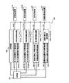
図1は、本実施形態に係る方法を実施する部品実装装置10の制御ブロック図である。
FIG. 1 is a control block diagram of a
この部品実装装置10は、電動式テープフィーダF(以下では単にテープフィーダFと記す)を取り付けるための差込口である複数のスロットSと、スロットSに取り付けられたテープフィーダFと通信して制御を行う制御部12と、制御部12がテープフィーダFと通信を行うための通信路14と、を有してなる。ここでは、部品実装装置10が有するスロットSの数は30である。
The
また、部品実装装置10は6つの吸着ノズル(図示せず)を備えており、同時吸着できる部品の最大数は6つである。このため、部品実装装置10は、6台のテープフィーダFが同時に動作するために必要となる電力を少なくとも供給することができる電源に接続されている。
The
スロットSは、テープフィーダFを取り付けるために部品実装装置10に設けられた差込口であり、それぞれが識別番号(以下IDと記すことがある)を持っている。図1に示す部品実装装置10が有するスロットSの数は30であり、各スロットSに割り振られたIDは1〜30である。
The slots S are insertion ports provided in the
スロットSに差し込まれて取り付けられたテープフィーダFは、部品実装装置10の電源が入ると、全てのテープフィーダFへの制御電源も入り自らが取り付けられたスロットSのIDを取得する。そして、テープフィーダFは、自らが取り付けられたスロットSのIDを通信路14を介して制御部12に通知する。この際、テープフィーダFは、自らが何mm送りフィーダであるかという情報も制御部12に通知する。これにより、制御部12は、IDが割り振られたスロットSごとに、それぞれ、テープフィーダFが取り付けられているかどうか、取り付けられている場合、その取り付けられたテープフィーダFは何mm送りフィーダであるかということを認識する。
When the power of the
テープフィーダFの送りピッチは、その種類によって、8mm、16mm、24mm、56mm等が存在する。原点位置合わせのためにテープを送る長さは、最大で送りピッチの長さとなるので、送りピッチの長さが長いほど、原点位置合わせにかかる最大の時間は長くなる。 The feed pitch of the tape feeder F is 8 mm, 16 mm, 24 mm, 56 mm, etc., depending on the type. Since the length of feeding the tape for the origin position alignment is the maximum of the feed pitch, the longer the feed pitch length is, the longer the maximum time for origin position alignment is.
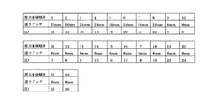
図2は、IDが1〜30の各スロットSごとに、テープフィーダFが取り付けられているかどうか、および、取り付けられたテープフィーダFが何mm送りフィーダであるかということを制御部12が認識した結果の一例である。
In FIG. 2, the
制御部12は、図2のような認識を行った後、原点位置合わせを行うテープフィーダFの順序を決定する。この順序の決定は、認識した各テープフィーダFを送りピッチの長さが長い順に並べ、送りピッチの長さが同じテープフィーダFがある場合は、取り付けられたスロットSのIDが若い順に並べる。このようにして、原点位置合わせを行う順序を決定した結果が図3である。
After performing the recognition as shown in FIG. 2, the
さらに、制御部12は、原点位置合わせを行う順序を決定した後、その決定結果に基づき、取り付けられたテープフィーダFの原点位置合わせを行うためのタイムチャートを作成する。
Further, the
ここで、部品実装装置10は、同時吸着できる部品の最大数が6つであり、部品実装装置10は、6台のテープフィーダFが同時に動作するために必要となる電力を少なくとも供給することができる電源に接続されている。そこで、同時に原点位置合わせを行うテープフィーダFの台数を6台に制限して原点位置合わせを順次行って、取り付けられた全てのテープフィーダFの原点位置合わせを行うようにすれば、テープフィーダFの原点位置合わせを行うことが原因となって、部品実装装置10の必要最大電力が大きくなることはない。そこで、同時に原点位置合わせを行うテープフィーダFの台数を6台に制限して原点位置合わせを順次行うためのタイムチャートを作成する。
Here, the
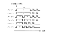
このためには、部品実装装置10に取り付けられたテープフィーダFを6つのグループ(ここでは、グループ1〜6とする。)に分ける必要がある。このグループ分けは、図3の原点位置合わせを行う順序に従って、テープフィーダFをグループ1〜6のいずれかに割り振っていくことで行う。この割り振りの際には、原点位置合わせを行うのに必要な最大の時間がなるべくグループ1〜6で均等になるように割り振る。具体的には、あるテープフィーダFをグループ1〜6のうちのどれかに割り振る際、グループ1〜6のうち、その時点で原点位置合わせを行うのに必要な最大の時間が最も少ないグループにテープフィーダFを割り振っていく。割り振られた必要最大時間が同じグループがある場合は、グループの番号の最も若いところに割り振る。
For this purpose, it is necessary to divide the tape feeder F attached to the
このようにして、部品実装装置10に取り付けられたテープフィーダFをグループ1〜6に割り振っていくと、図4のようなタイムチャートが得られる。図4において、あるテープフィーダFが原点位置合わせを行うのに必要な最大の時間は、そのテープフィーダFに対応した高レベル部の長さで表している。高レベル部の下に記された数字が、そのテープフィーダFが取り付けられたスロットSのIDである。例えば、ID11のスロットSに取り付けられたテープフィーダFが原点位置合わせを行うのに必要な最大の時間は、図4において、長さL11で表されている。
In this way, when the tape feeders F attached to the
次に、本実施形態に係る方法によって、各テープフィーダFの原点位置合わせがどのように行われるかについて、図5に示すフローチャートを用いて説明する。 Next, how the origin position alignment of each tape feeder F is performed by the method according to the present embodiment will be described with reference to the flowchart shown in FIG.
部品実装装置10の電源が入ると(ステップS1)、各テープフィーダFは、自らが取り付けられているスロットSのIDを取得する(ステップS2)。そして、各テープフィーダFは、自らが取り付けられているスロットSのIDと、自らが何mm送りフィーダであるかということを、通信路14を介して制御部12に通知する(ステップS3)。
When the power of the
これにより、制御部12は、IDが1〜30の各スロットSごとに、テープフィーダFが取り付けられているかどうか、および、取り付けられたテープフィーダFが何mm送りフィーダであるかということを認識する(ステップS4)。
Thereby, the
次に、部品実装装置10の原点位置合わせボタン(図示せず)を押して、取り付けられた各テープフィーダFについて原点位置合わせを開始する(ステップS5)。
Next, an origin position alignment button (not shown) of the
テープフィーダFの原点位置合わせの際、まず、部品実装装置10の制御部12は、同時吸着できる部品の最大数を確認する(ステップS6)。ここでは、部品実装装置10が同時吸着することができる部品の最大数は6である。
When aligning the origin of the tape feeder F, first, the
次に、認識した各テープフィーダFを送りピッチの長さが長い順に並べ、送りピッチの長さが同じテープフィーダFがある場合は、取り付けられたスロットSのIDが若い順に並べて、図3に示すように、認識した各テープフィーダFの原点位置合わせの順序を設定する(ステップS7)。 Next, the recognized tape feeders F are arranged in ascending order of the feed pitch length, and when there are tape feeders F having the same feed pitch length, the IDs of the installed slots S are arranged in ascending order, and FIG. As shown, the sequence of the origin alignment of each recognized tape feeder F is set (step S7).
次に、ステップS7で設定した各テープフィーダFの原点位置合わせの順序に従って、各テープフィーダFをグループ1〜6に割り振っていく。その際、前述したように、割り振るテープフィーダFが原点位置合わせに要する時間を考慮して割り振り、原点位置合わせを行うのに必要な最大の時間がなるべくグループ1〜6で均等になるように割り振って、図4に示すようなタイムチャートを得る(ステップS8)。
Next, the tape feeders F are allocated to the
次に、ステップS8で得たタイムチャートに従って、グループ1〜6について同時に原点位置合わせを行っていく(ステップS9)。この際、制御部12からテープフィーダFに通信路14を介して、原点位置合わせをする指示がなされる。原点位置合わせが完了したテープフィーダFは、通信路14を介して、原点位置合わせが完了したことを制御部12に通知する。この通知を受けた制御部12は、ステップS8で得たタイムチャートに従って、次のテープフィーダFに原点位置合わせを指示する。このようにして、ステップS8で得たタイムチャートに従って、認識した全てのテープフィーダFの原点位置合わせを実行する。
Next, according to the time chart obtained in step S8, the origin positions are simultaneously adjusted for
制御部12が認識した全てのテープフィーダFについて原点位置合わせが完了したかどうかを判断し(ステップS10)、全てのテープフィーダFについて原点位置合わせが完了したら、原点位置合わせ動作は完了する。 It is determined whether or not the home position alignment has been completed for all the tape feeders F recognized by the control unit 12 (step S10), and when the home position alignment has been completed for all the tape feeders F, the home position alignment operation is completed.
以上のようにして部品実装装置10に取り付けられたテープフィーダFについて原点位置合わせを行うことによって、同時に原点位置合わせを行うテープフィーダFの台数を、同時吸着できる部品の最大数と同じ台数に制限することにより、部品実装装置10が必要とする最大電力を、同時吸着できる部品の最大数と同じ台数のテープフィーダFを駆動するのに必要な電力以内に常にすることができる。
By performing origin position alignment for the tape feeder F attached to the
また、部品実装装置10に取り付けられたテープフィーダFは、同時吸着できる部品の最大数とグループ数が同じとなるように割り振られるが、ステップS8で得られたタイムチャートでは、原点位置合わせに要する最大の時間がグループ間でなるべく均等になるように割り振られているので、原点位置合わせを完了するのに要する時間が特定のグループのみ長くかかるということがなく、全ての原点位置合わせ動作を完了するまでの時間は短くなる。
The tape feeder F attached to the
以上説明した実施形態では、部品実装装置10のスロットSの数は30であり、部品実装装置10に取り付けることができるテープフィーダFの台数は最大で30台であったが、スロットSの数を30より多くして、部品実装装置10に取り付けるテープフィーダFの台数を30台よりも多くしてもよい。この場合であっても、同時に原点位置合わせを行うテープフィーダFの台数を、同時吸着できる部品の最大数と同じ台数に制限することができ、部品実装装置10が必要とする最大電力を、同時吸着できる部品の最大数と同じ台数のテープフィーダFを駆動するのに必要な電力以内に常にすることができる。
In the embodiment described above, the number of slots S of the
また、以上説明した実施形態では、部品実装装置10が同時吸着できる部品の最大数は6つであり、部品実装装置10は6台のテープフィーダFが同時に動作するために必要となる電力を少なくとも供給することができる電源に接続されている。そこで、部品実装装置10に取り付けられたテープフィーダFについて、同時に原点位置合わせを行う台数を6台に制限して原点位置合わせを順次行うようにしたが、同時に原点位置合わせを行う台数は6台でなくてもよく、5台以下あるいは7台以上であってもよい。
In the embodiment described above, the maximum number of components that can be picked up simultaneously by the
ただし、同時に原点位置合わせを行う台数を5台以下とした場合、同時に原点位置合わせを行う台数を6台としたときよりも、部品実装装置10に取り付けられた全てのテープフィーダFについて原点位置合わせを終了するのに要する時間は長くなる。また、同時に原点位置合わせを行う台数を7台以上とした場合、同時に原点位置合わせを行う台数を6台としたときよりも、部品実装装置10の必要最大電力は大きくなり、テープフィーダFの原点位置合わせを行うことが原因となって、部品実装装置10の必要最大電力が大きくなり、部品実装装置10のために用意する必要のある電源の容量が大きくなってしまう。
However, when the number of home position alignments is 5 or less at the same time, the home position alignment is performed for all tape feeders F attached to the
したがって、同時吸着できる部品の最大数が6つである部品実装装置10においては、同時に原点位置合わせを行う台数は6台とすることが好ましい。
Therefore, in the
また、以上説明した実施形態では、部品供給装置としてテープフィーダFを用いたが、用いる部品供給装置はテープフィーダに限定されない。 Moreover, in embodiment described above, although the tape feeder F was used as a component supply apparatus, the component supply apparatus to be used is not limited to a tape feeder.
10…部品実装装置
12…制御部
14…通信路
F…テープフィーダ
S…スロット
DESCRIPTION OF
Claims (2)
前記スロットに取り付けられた電動式部品供給装置を、部品実装装置から電動式部品供給装置に同時に供給可能な電力の範囲内で複数のグループに分け、分けられたグループごとに原点位置合わせを行う電動式部品供給装置の順序を決定し、前記複数のグループについて同時に原点位置合わせを行うことを特徴とする部品実装装置における電動式部品供給装置の原点位置合わせ制御方法。 A plurality of slots for attaching the electric component supply device, a control unit for controlling the operation of the electric component supply device attached to the slot, and a communication path between the electric component supply device and the control unit In a component mounting apparatus having
The electric component supply device attached to the slot is divided into a plurality of groups within the range of electric power that can be supplied simultaneously from the component mounting device to the electric component supply device, and the origin is aligned for each divided group. A method of controlling an origin alignment of an electric component supply apparatus in a component mounting apparatus, wherein the order of the electronic component supply apparatus is determined, and the origin alignment is performed simultaneously for the plurality of groups.
Priority Applications (2)
| Application Number | Priority Date | Filing Date | Title |
|---|---|---|---|
| JP2008209787A JP5174579B2 (en) | 2008-08-18 | 2008-08-18 | Method for controlling origin alignment of electric component supply device in component mounting apparatus |
| CN200910167105.5A CN101657087B (en) | 2008-08-18 | 2009-08-18 | Control method of electric component feeding device |
Applications Claiming Priority (1)
| Application Number | Priority Date | Filing Date | Title |
|---|---|---|---|
| JP2008209787A JP5174579B2 (en) | 2008-08-18 | 2008-08-18 | Method for controlling origin alignment of electric component supply device in component mounting apparatus |
Publications (2)
| Publication Number | Publication Date |
|---|---|
| JP2010045295A true JP2010045295A (en) | 2010-02-25 |
| JP5174579B2 JP5174579B2 (en) | 2013-04-03 |
Family
ID=41711083
Family Applications (1)
| Application Number | Title | Priority Date | Filing Date |
|---|---|---|---|
| JP2008209787A Active JP5174579B2 (en) | 2008-08-18 | 2008-08-18 | Method for controlling origin alignment of electric component supply device in component mounting apparatus |
Country Status (2)
| Country | Link |
|---|---|
| JP (1) | JP5174579B2 (en) |
| CN (1) | CN101657087B (en) |
Cited By (3)
| Publication number | Priority date | Publication date | Assignee | Title |
|---|---|---|---|---|
| WO2015177834A1 (en) * | 2014-05-19 | 2015-11-26 | ヤマハ発動機株式会社 | Component mounting apparatus and method for arranging component mounting apparatus |
| WO2017094192A1 (en) * | 2015-12-04 | 2017-06-08 | 富士機械製造株式会社 | Feeder control device and control method, and component supply device |
| WO2018225170A1 (en) | 2017-06-07 | 2018-12-13 | 株式会社Fuji | Component mounting machine |
Families Citing this family (2)
| Publication number | Priority date | Publication date | Assignee | Title |
|---|---|---|---|---|
| CN101835371A (en) * | 2010-03-26 | 2010-09-15 | 东莞市正可电子科技有限公司 | Fully-automatic plug-in machine control system |
| CN103269576B (en) * | 2013-05-31 | 2016-01-20 | 哈尔滨工业大学 | The method of full-automatic chip mounter nozzle head axle initial point quick position |
Citations (1)
| Publication number | Priority date | Publication date | Assignee | Title |
|---|---|---|---|---|
| JP2007048891A (en) * | 2005-08-09 | 2007-02-22 | Yamaha Motor Co Ltd | Surface mounting machine |
Family Cites Families (3)
| Publication number | Priority date | Publication date | Assignee | Title |
|---|---|---|---|---|
| DE10152408A1 (en) * | 2000-10-25 | 2002-05-16 | Matsushita Electric Ind Co Ltd | System for automatic mounting of electronic components onto a circuit board uses camera scanning of board |
| CN100438743C (en) * | 2001-10-16 | 2008-11-26 | 松下电器产业株式会社 | Moving belt transveyer and electronic parts mounting device and electric parts transporting method |
| JP4845113B2 (en) * | 2006-09-12 | 2011-12-28 | 富士機械製造株式会社 | Electronic component mounting machine and electronic component supply device |
-
2008
- 2008-08-18 JP JP2008209787A patent/JP5174579B2/en active Active
-
2009
- 2009-08-18 CN CN200910167105.5A patent/CN101657087B/en active Active
Patent Citations (1)
| Publication number | Priority date | Publication date | Assignee | Title |
|---|---|---|---|---|
| JP2007048891A (en) * | 2005-08-09 | 2007-02-22 | Yamaha Motor Co Ltd | Surface mounting machine |
Cited By (7)
| Publication number | Priority date | Publication date | Assignee | Title |
|---|---|---|---|---|
| WO2015177834A1 (en) * | 2014-05-19 | 2015-11-26 | ヤマハ発動機株式会社 | Component mounting apparatus and method for arranging component mounting apparatus |
| JPWO2015177834A1 (en) * | 2014-05-19 | 2017-04-20 | ヤマハ発動機株式会社 | Component mounter and setup method of component mounter |
| KR101816621B1 (en) | 2014-05-19 | 2018-01-09 | 야마하하쓰도키 가부시키가이샤 | Component mounting apparatus and method for arranging component mounting apparatus |
| WO2017094192A1 (en) * | 2015-12-04 | 2017-06-08 | 富士機械製造株式会社 | Feeder control device and control method, and component supply device |
| WO2018225170A1 (en) | 2017-06-07 | 2018-12-13 | 株式会社Fuji | Component mounting machine |
| JPWO2018225170A1 (en) * | 2017-06-07 | 2020-05-21 | 株式会社Fuji | Parts mounting machine |
| US11357151B2 (en) | 2017-06-07 | 2022-06-07 | Fuji Corporation | Component mounting machine |
Also Published As
| Publication number | Publication date |
|---|---|
| CN101657087B (en) | 2014-05-07 |
| CN101657087A (en) | 2010-02-24 |
| JP5174579B2 (en) | 2013-04-03 |
Similar Documents
| Publication | Publication Date | Title |
|---|---|---|
| JP5174579B2 (en) | Method for controlling origin alignment of electric component supply device in component mounting apparatus | |
| JP6310058B2 (en) | Image processing apparatus and substrate production system | |
| JP2006339392A (en) | Component mounting apparatus | |
| JP2005005288A (en) | Electronic component mounter and mounting method | |
| JP2016031959A (en) | Component mount device and component mount method | |
| US20150245493A1 (en) | Component mounting method and component mounting system | |
| US10765048B2 (en) | Component mounting system, component sorting method, and component mounter | |
| JP6021374B2 (en) | Component mounting apparatus and component mounting method | |
| JP6646916B2 (en) | Image processing apparatus and image processing method for substrate | |
| JP2009004400A (en) | Mounting machine and component suction device | |
| JP5078812B2 (en) | Board work system | |
| CN109196971B (en) | Component mounting system | |
| JP4537233B2 (en) | Image recognition apparatus and surface mounter | |
| JP7213106B2 (en) | Component mounter | |
| JP4228868B2 (en) | Electronic component mounting method | |
| US11778798B2 (en) | Information processing device, work system, and determination method | |
| JP4203116B2 (en) | Component mounting equipment | |
| JP2011023616A (en) | Method and apparatus for mounting component | |
| JP4805084B2 (en) | Imaging control apparatus and surface mounter | |
| JP2005276909A (en) | Apparatus for mounting electronic component | |
| JP5981996B2 (en) | Mounting system | |
| JP2023068698A (en) | Component mounting system, component mounting device, and component mounting method | |
| JP6706824B2 (en) | Component mounting device | |
| JP2021118265A (en) | Component mounting device and component mounting system | |
| JP4913769B2 (en) | Mounting method of electronic parts |
Legal Events
| Date | Code | Title | Description |
|---|---|---|---|
| A621 | Written request for application examination |
Free format text: JAPANESE INTERMEDIATE CODE: A621 Effective date: 20110808 |
|
| A977 | Report on retrieval |
Free format text: JAPANESE INTERMEDIATE CODE: A971007 Effective date: 20120824 |
|
| A131 | Notification of reasons for refusal |
Free format text: JAPANESE INTERMEDIATE CODE: A131 Effective date: 20120828 |
|
| A521 | Written amendment |
Free format text: JAPANESE INTERMEDIATE CODE: A523 Effective date: 20121026 |
|
| TRDD | Decision of grant or rejection written | ||
| A01 | Written decision to grant a patent or to grant a registration (utility model) |
Free format text: JAPANESE INTERMEDIATE CODE: A01 Effective date: 20121211 |
|
| A61 | First payment of annual fees (during grant procedure) |
Free format text: JAPANESE INTERMEDIATE CODE: A61 Effective date: 20121228 |
|
| R150 | Certificate of patent or registration of utility model |
Ref document number: 5174579 Country of ref document: JP Free format text: JAPANESE INTERMEDIATE CODE: R150 |