JP2010038820A - Ultrasonic inspection device - Google Patents
Ultrasonic inspection device Download PDFInfo
- Publication number
- JP2010038820A JP2010038820A JP2008204223A JP2008204223A JP2010038820A JP 2010038820 A JP2010038820 A JP 2010038820A JP 2008204223 A JP2008204223 A JP 2008204223A JP 2008204223 A JP2008204223 A JP 2008204223A JP 2010038820 A JP2010038820 A JP 2010038820A
- Authority
- JP
- Japan
- Prior art keywords
- pipe
- inspection apparatus
- ultrasonic inspection
- ultrasonic
- reflected
- Prior art date
- Legal status (The legal status is an assumption and is not a legal conclusion. Google has not performed a legal analysis and makes no representation as to the accuracy of the status listed.)
- Granted
Links
Images


Abstract
Description
本発明は、配管継手のソケット部とこれに挿入された配管とを接合した隅肉溶接部を検査する超音波検査装置に関する。 The present invention relates to an ultrasonic inspection apparatus that inspects a fillet welded portion that joins a socket portion of a pipe joint and a pipe inserted into the socket portion.
各種産業における機器や構造物において、金属部材の溶接部は、全体の強度や信頼性を左右する非常に重要な部位であり、様々な方法で検査が行われている。例えば原子力発電所や火力発電所等に設置された配管系統には、配管継手のソケット部とこれに挿入された配管とを接合した隅肉溶接部が有り、この隅肉溶接部に対して外観検査や、溶接部に内在する欠陥(例えば溶接金属の溶け込み不良や、機器の運転中の振動に起因する疲労割れ等)を検出する非破壊検査が行われている。非破壊検査方法の一つとしては、欠陥検出能力が高く迅速に行うことができる超音波検査方法がある。 In equipment and structures in various industries, a welded portion of a metal member is a very important part that affects the overall strength and reliability, and is inspected by various methods. For example, a piping system installed in a nuclear power plant or a thermal power plant has a fillet weld that joins a socket of a pipe joint and a pipe inserted into the pipe joint. Non-destructive inspection is performed to detect inspections and defects inherent in welds (for example, poor weld metal penetration and fatigue cracks caused by vibrations during operation of equipment). As one of the nondestructive inspection methods, there is an ultrasonic inspection method that has a high defect detection capability and can be performed quickly.
ここで従来、配管継手のソケット部と配管との隅肉溶接部を検査する超音波検査装置として、ソケット部の外表面に配置された斜角探触子と、この斜角探触子をソケット部の円周方向及び軸方向に走査する駆動装置とを備えたものが開示されている(例えば、特許文献1参照)。この超音波検査装置では、斜角探触子から発生する横波と、その横波の一部がソケット部の内表面にてモード変換を起こして発生する二次クリーピング波とを利用し、隅肉溶接部の探傷検査を行うようになっている。具体的に説明すると、例えば隅肉溶接部のルート付近で溶け込み不良が生じていた場合は、二次クリーピング波が溶け込み不良のコーナ部で反射されて斜角探触子で受信され、一方、横波が溶け込み不良の端部で反射されて斜角探触子で受信される。また、例えば探傷面に対して垂直方向や斜め方向となる疲労割れが生じていた場合は、横波が疲労割れで反射されて斜角探触子で受信される。したがって、様々な欠陥を一度に検出することが可能となっている。 Conventionally, as an ultrasonic inspection apparatus for inspecting a fillet welded part between a socket part of a pipe joint and a pipe, an oblique probe arranged on the outer surface of the socket part, and this oblique probe is socketed. And a driving device that scans in the circumferential direction and the axial direction of the part (see, for example, Patent Document 1). In this ultrasonic inspection apparatus, a fillet is formed using a transverse wave generated from an oblique probe and a secondary creeping wave generated by mode conversion of a part of the transverse wave on the inner surface of the socket part. A flaw detection inspection is performed on the welded part. Specifically, for example, if there is a poor penetration near the root of the fillet weld, the secondary creeping wave is reflected at the corner of the poor penetration and received by the bevel probe, The transverse wave is reflected at the end of poor penetration and received by the bevel probe. For example, when a fatigue crack that is perpendicular or oblique to the flaw detection surface has occurred, the transverse wave is reflected by the fatigue crack and received by the oblique probe. Therefore, it is possible to detect various defects at a time.
しかしながら、上記従来技術には以下のような課題が存在する。例えば小口径(20A〜50A程度の)エルボのソケット部と配管との隅肉溶接部の検査においては、小口径エルボのソケット部における腹側(曲げ内側)領域が狭く、また表面曲率の影響により、斜角探触子をソケット部の外周面に安定して配置することが困難となる。すなわち、上記従来技術では、小口径エルボのソケット部と配管との隅肉溶接部の検査に対応することができなかった。そこで、例えば斜角探触子を配管の非挿入部の外表面に配置して検査する方法が考えられるものの、隅肉溶接部のエルボ側境界付近でエルボ側境界に対しほぼ平行方向(言い換えれば、探傷面に対して垂直方向)となるように生じた欠陥を検出することは困難であった。 However, there are the following problems in the above-described prior art. For example, in the inspection of a fillet welded portion of a small diameter (about 20A to 50A) elbow socket part and piping, the ventral side (bending inside) region in the socket part of the small diameter elbow is narrow, and due to the influence of surface curvature Therefore, it becomes difficult to stably arrange the oblique angle probe on the outer peripheral surface of the socket portion. In other words, the above-described conventional technology cannot cope with the inspection of the fillet welded portion between the socket portion of the small-diameter elbow and the pipe. For this reason, for example, a method of inspecting by placing an oblique probe on the outer surface of the non-insertion portion of the pipe can be considered, but in the vicinity of the elbow side boundary of the fillet welded portion, it is almost parallel to the elbow side boundary (in other words It was difficult to detect a defect that occurred in a direction perpendicular to the flaw detection surface.
本発明の目的は、例えば小口径エルボのソケット部と配管との隅肉溶接部の検査に対応することができ、隅肉溶接部のエルボ側境界付近でエルボ側境界に対しほぼ平行方向となるように生じた欠陥を検出することができる超音波検査装置を提供することにある。 The object of the present invention can correspond to, for example, the inspection of the fillet welded portion between the socket portion of the small-diameter elbow and the pipe, and is substantially parallel to the elbow side boundary near the elbow side boundary of the fillet welded portion. An object of the present invention is to provide an ultrasonic inspection apparatus capable of detecting a defect that has occurred.
(1)上記目的を達成するために、本発明は、配管継手のソケット部とこれに挿入された配管とを接合した隅肉溶接部を検査する超音波検査装置において、前記配管の非挿入部の外周側に配置されて、非溶接領域である前記配管の外表面に入射する超音波を送信する第1の送信素子と、前記配管の非挿入部の外周側に配置されて、前記隅肉溶接部の欠陥で反射され前記隅肉溶接部の外表面から出射された反射波を受信する第1の受信素子とを有する。 (1) In order to achieve the above object, the present invention provides an ultrasonic inspection apparatus for inspecting a fillet welded portion in which a socket portion of a pipe joint and a pipe inserted into the pipe joint are joined. A first transmitting element that transmits an ultrasonic wave incident on an outer surface of the pipe that is a non-weld region, and a fillet that is disposed on the outer peripheral side of a non-insertion portion of the pipe. And a first receiving element that receives a reflected wave reflected from a defect of the welded portion and emitted from the outer surface of the fillet welded portion.
このように本発明においては、第1の送信素子及び第1の受信素子を、配管継手のソケット部の外周側に配置しないで、配管の非挿入部の外周側に配置するので、例えば小口径エルボのソケット部と配管との隅肉溶接部の検査に対応することができる。そして、第1の送信素子から配管の外表面に入射された超音波は配管の内表面で反射されて隅肉溶接部に到達し、例えば隅肉溶接部のエルボ側境界付近でエルボ側境界に対しほぼ平行方向となる欠陥(例えば疲労割れ)が生じていた場合に、その欠陥で反射されて隅肉溶接部の外表面から出射され、その反射波が第1の受信素子で受信される。これにより、隅肉溶接部のエルボ側境界付近でエルボ側境界に対しほぼ平行方向となるように生じた欠陥を検出することができる。 Thus, in the present invention, the first transmitting element and the first receiving element are not arranged on the outer peripheral side of the socket part of the pipe joint, but are arranged on the outer peripheral side of the non-insertion part of the pipe. It can correspond to the inspection of the fillet welded portion between the elbow socket and the pipe. Then, the ultrasonic wave incident on the outer surface of the pipe from the first transmitting element is reflected by the inner surface of the pipe and reaches the fillet weld, for example, near the elbow side boundary of the fillet weld. On the other hand, when a defect (for example, fatigue crack) in a substantially parallel direction has occurred, it is reflected by the defect and emitted from the outer surface of the fillet weld, and the reflected wave is received by the first receiving element. Thereby, the defect produced so that it may become a substantially parallel direction with respect to the elbow side boundary near the elbow side boundary of a fillet welded part can be detected.
(2)上記(1)において、好ましくは、前記第1の送信素子及び前記第1の受信素子は、前記配管における軸方向位置及び周方向位置が互いに異なるように配置する。 (2) In the above (1), preferably, the first transmitting element and the first receiving element are arranged so that an axial position and a circumferential position in the pipe are different from each other.
(3)上記(1)又は(2)において、好ましくは、前記配管の非挿入部の外周側に配置されて、前記隅肉溶接部の欠陥で反射され非溶接領域である前記配管の外表面から出射された反射波を受信する第2の受信素子を有する。 (3) In the above (1) or (2), preferably, the outer surface of the pipe which is disposed on the outer peripheral side of the non-insertion part of the pipe and is reflected by a defect of the fillet weld part and is a non-weld region A second receiving element for receiving the reflected wave emitted from
このように本発明においては、第2の受信素子も配管の非挿入部の外周側に配置するので、例えば小口径エルボのソケット部と配管との隅肉溶接部の検査に対応することができる。そして、第1の送信素子から配管の外表面に入射された超音波は配管の内表面で反射されて隅肉溶接部に到達し、例えば隅肉溶接部のルート付近で欠陥(例えば溶け込み不良)が生じていたり、のど厚方向に(言い換えれば、探傷面に対して斜め方向に)欠陥が生じていた場合に、その欠陥で反射されて戻って配管の外表面から出射され、その反射波が第2の受信素子で受信される。これにより、隅肉溶接部のルート付近で生じた欠陥やのど厚方向に生じた欠陥などを検出することができる。したがって、第1及び第2の受信素子によって様々な欠陥を一度に検出することができ、検査作業の効率を向上させることができる。 As described above, in the present invention, since the second receiving element is also arranged on the outer peripheral side of the non-insertion portion of the pipe, for example, it can cope with the inspection of the fillet welded portion between the socket portion of the small-diameter elbow and the pipe. . Then, the ultrasonic wave incident on the outer surface of the pipe from the first transmitting element is reflected by the inner surface of the pipe and reaches the fillet weld, for example, a defect (for example, poor penetration) near the fillet weld. If there is a defect in the throat thickness direction (in other words, in an oblique direction with respect to the flaw detection surface), the defect is reflected and returned from the outer surface of the pipe, and the reflected wave is Received by the second receiving element. Thereby, a defect generated near the root of the fillet weld or a defect generated in the throat thickness direction can be detected. Accordingly, various defects can be detected at a time by the first and second receiving elements, and the efficiency of the inspection work can be improved.
(4)上記(3)において、好ましくは、前記第1の送信素子及び前記第2の受信素子は、それらの機能を共有する送受信素子である。 (4) In the above (3), preferably, the first transmission element and the second reception element are transmission / reception elements that share their functions.
(5)上記(1)〜(4)のいずれか1つにおいて、好ましくは、前記配管の非挿入部の外周側に配置されて、前記隅肉溶接部の外表面に入射する超音波を送信する第2の送信素子を有する。 (5) In any one of the above (1) to (4), preferably, an ultrasonic wave that is disposed on the outer peripheral side of the non-insertion portion of the pipe and is incident on the outer surface of the fillet weld portion is transmitted. A second transmitting element.
このように本発明においては、第2の送信素子も配管の非挿入部の外周側に配置するので、例えば小口径エルボのソケット部と配管との隅肉溶接部の検査に対応することができる。そして、例えば隅肉溶接部のルート付近で欠陥(例えば溶け込み不良)が生じていた場合には、第2の送信素子から隅肉溶接部に入射された超音波がその欠陥で反射されて戻って隅肉溶接部の外表面から出射され、その反射波が第1の受信素子で受信される。これにより、超音波の伝達経路を比較的短くすることができるため、例えば隅肉溶接部のルート付近で生じた欠陥などが小さい場合でも検出することができる。 Thus, in the present invention, since the second transmitting element is also arranged on the outer peripheral side of the non-insertion portion of the pipe, for example, it can cope with the inspection of the fillet welded portion between the socket portion of the small-diameter elbow and the pipe. . For example, when a defect (for example, poor penetration) occurs near the root of the fillet weld, the ultrasonic wave incident on the fillet weld from the second transmitting element is reflected by the defect and returned. The light is emitted from the outer surface of the fillet weld and the reflected wave is received by the first receiving element. Thereby, since the transmission path of the ultrasonic wave can be made relatively short, for example, even when a defect or the like generated near the root of the fillet weld is small, it can be detected.
(6)上記(5)において、好ましくは、前記第2の送信素子及び前記第1の受信素子は、それらの機能を共有する送受信素子である。 (6) In the above (5), preferably, the second transmission element and the first reception element are transmission / reception elements that share their functions.
(7)上記(1)〜(6)のいずれか1つにおいて、好ましくは、前記第1の送信素子及び前記第2の送信素子のうちの少なくとも一方を複数設け、これら複数の送信素子からの球面超音波の送信及び位相をそれぞれ制御する素子制御手段を設ける。 (7) In any one of the above (1) to (6), preferably, a plurality of at least one of the first transmission element and the second transmission element is provided, and Element control means for controlling transmission and phase of spherical ultrasonic waves is provided.
(8)上記(1)〜(7)のいずれか1つにおいて、好ましくは、前記配管の非挿入部及び前記隅肉溶接部を覆うような筒状のシューを取り付ける。 (8) In any one of the above (1) to (7), preferably, a cylindrical shoe is attached so as to cover the non-insertion portion of the pipe and the fillet weld portion.
(9)上記(8)において、好ましくは、前記シューは、前記隅肉溶接部と接触する部分に柔軟性のゲル状部材を設ける。 (9) In the above (8), preferably, the shoe is provided with a flexible gel-like member at a portion in contact with the fillet welded portion.
本発明によれば、例えば小口径エルボのソケット部と配管との隅肉溶接部の検査に対応することができ、隅肉溶接部のエルボ側境界付近でエルボ側境界に対しほぼ平行方向となるように生じた欠陥を検出することができる。 According to the present invention, for example, it is possible to cope with the inspection of the fillet welded portion between the socket portion of the small-diameter elbow and the pipe, and the direction is substantially parallel to the elbow side boundary near the elbow side boundary of the fillet welded portion. Thus, the generated defect can be detected.
以下、本発明の一実施形態を、図面を参照しつつ説明する。 Hereinafter, an embodiment of the present invention will be described with reference to the drawings.
図1は、本発明の超音波検査装置の一実施形態の全体構成を表す概略図である。 FIG. 1 is a schematic diagram showing the overall configuration of an embodiment of the ultrasonic inspection apparatus of the present invention.
この図1において、超音波検査装置は、例えばエルボ1のソケット部1aとこれに挿入された配管(配管母材)2とを接合した隅肉溶接部(詳細には、溶接ビード3及び熱影響部を含む部分)の検査を目的とするものである。この超音波検査装置は、第1の斜角探触子4及び第2の斜角探触子5を備えた探触子移動装置6(走査機構)と、この探触子移動装置6を駆動制御して斜角探触子4,5の位置を制御する探触子位置制御装置7と、斜角探触子4による超音波の送信及びその反射波の受信を制御する第1の探傷制御装置8と、斜角探触子5による反射波の受信を制御する第2の探傷制御装置9と、これら探触子位置制御装置7及び探傷制御装置8,9を連携して制御するとともに、探傷情報(詳細には、斜角探触子4,5の位置情報と斜角探触子4,5で受信した反射波の波形情報を含む)を収録する中央制御装置10と、この中央制御装置10で収録された探傷情報に基づき、反射波を配管2の板厚方向断面の反射位置に変換して画像表示する断面表示/欠陥識別装置11とを備えている。
In FIG. 1, the ultrasonic inspection apparatus includes, for example, a fillet welded portion (in detail, a
配管2の外周側には、配管2の非挿入部及び溶接ビード3を覆うように筒状のシュー12が固定機構13によって固定されている。シュー12は、例えばアクリルで形成されており、溶接ビード3との接触部分には、溶接ビード3の形状に沿って密着するための柔軟性のゲル状接触媒質(ゲル状部材)14が設けられている。シュー12の外周側には、周方向に延在するガイドレール15が取り付けられている。なお、シュー12及びゲル状接触媒質14は、配管2の外周側に取り付け可能なように分割構造となっている。また、ガイドレール15は、シュー12の外周側に取り付け可能なように分割構造となっている。
A
探触子移動装置6は、ガイドレール15に噛み合う歯車16と、この歯車16を回転制御する周方向移動制御機構17とを備えており、ガイドレール15に沿って移動可能としている。すなわち、斜角探触子4,5をシュー12の周方向(言い換えれば、配管2の周方向)に移動させることが可能となっている。また、探触子移動装置6は、シュー12の軸方向(図1中左右方向)に延在し、上記斜角探触子4,5が取り付けられたアーム18と、斜角探触子4,5のそれぞれとアーム18との間に設けられ、斜角探触子4,5を液状接触媒質(図示せず)を介してシュー12の外表面に密着させる付勢力を付与するスプリング機構(図示せず)と、アーム18をシュー12の軸方向に移動可能に支持する複数の車輪19と、これら車輪19を回転制御してアーム18をシュー2の軸方向に移動させる軸方向移動制御機構20とを備えており、斜角探触子4,5をシュー12の軸方向(言い換えれば、配管2の軸方向)に移動させることが可能となっている。
The
ここで本実施形態の大きな特徴として、第1の斜角探触子4は、配管2の非挿入部の外周側に配置されており、非溶接領域である配管2の外表面に対し傾斜した角度で入射するように超音波を送信するとともに、隅肉溶接部の欠陥(詳細は後述)などで反射され非溶接領域である配管2の外表面から出射された反射波を受信する送受信素子4a(後述の図2(a)及び図3参照)を有している(なお、これに代えて、送信素子と受信素子を有してもよい)。第2の斜角探触子5は、配管2の非挿入部(及び隅肉溶接部)の外周側に配置されており、隅肉溶接部の欠陥(詳細は後述)などで反射され溶接ビード3の外表面から出射された反射波を受信する受信素子5a(後述の図2(a)及び図3参照)を有している。また、斜角探触子4,5は、配管2における軸方向位置だけでなく周方向位置も互いに異なるように配置されており、隅肉溶接部に向けての斜角探触子4の送受信角度と斜角探触子5の受信角度とを異ならせている(後述の図2(b)参照)。このような斜角探触子4,5における超音波の伝達経路を以下説明する。
Here, as a major feature of the present embodiment, the
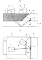
図2(a)は、本実施形態における超音波の伝達経路の一例を表す断面図であり、図2(b)は、平面図である。また、図3は、本実施形態における超音波の伝達経路の他の例を表す断面図である。 FIG. 2A is a cross-sectional view illustrating an example of an ultrasonic transmission path in the present embodiment, and FIG. 2B is a plan view. FIG. 3 is a cross-sectional view illustrating another example of an ultrasonic transmission path in the present embodiment.
斜角探触子4から送信された超音波は、シュー12及び液状接触媒質を介して配管2の外表面に入射し、配管2の内表面で1回反射して隅肉溶接部に到達する。そして、図2(a)及び図2(b)で示すように、隅肉溶接部に到達した超音波の一部は、例えば隅肉溶接部のエルボ1側境界付近でエルボ側境界に対しほぼ平行方向(言い換えれば、探傷面に対し垂直方向)となる疲労割れA1が生じていた場合に、その疲労割れA1で反射し、溶接ビード3の外表面から出射し、ゲル状媒質14及びシュー12を介して斜角探触子5で受信される。これにより、疲労割れA1が検出される。
The ultrasonic wave transmitted from the
また、図2(a)、図2(b)、及び図3で示すように、隅肉溶接部に到達した超音波の一部は、例えば隅肉溶接部のルート付近で溶け込み不良A2が生じていた場合に、その溶け込み不良A1の端部で反射し、同じ経路を戻って配管2の外表面の非溶接領域から出射し、シュー12及び液状接触媒質を介して斜角探触子4で受信される。なお、例えば溶け込み不良A2が生じていない場合は、エルボ1のソケット部1aと配管2の挿入部との隙間の端部で反射し、同様の経路を経て斜角探触子4で受信される。そのため、予め得られている隅肉溶接部などの設計寸法と反射波の反射位置情報から、溶け込み不良A2であるかどうかが判断される。
Further, as shown in FIGS. 2 (a), 2 (b), and 3, a part of the ultrasonic wave that reaches the fillet welded portion has a poor penetration A2 near the root of the fillet welded portion, for example. If it is, the light is reflected at the end of the poor penetration A1, returns through the same path, exits from the non-welded area on the outer surface of the
また、図3で示すように、隅肉溶接部に到達した超音波の一部は、例えばのど厚方向に(言い換えれば、探傷面に対して斜め方向に)疲労割れA3が生じていた場合に、その疲労割れA3で反射し、同じ経路を戻って配管2の外表面から出射し、シュー12及び液状接触媒質を介して斜角探触子4で受信される。これにより、疲労割れA3が検出される。
In addition, as shown in FIG. 3, when a part of the ultrasonic wave reaching the fillet weld has fatigue crack A3 in the throat thickness direction (in other words, in the oblique direction with respect to the flaw detection surface), for example. The light is reflected by the fatigue crack A3, returns along the same path, is emitted from the outer surface of the
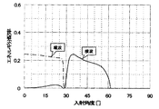
なお、本実施形態では、配管2の外表面から入射した超音波を配管2の内表面で一回反射させて隅肉溶接部に到達させるので、隅肉溶接部の探傷に用いる超音波のモードとしては横波を利用することが望ましい。そして、シュー12と配管2との間の液状接触媒質では縦波しか伝達しないことから、シュー12から配管2に入射するときに縦波から横波に変換することになる。また、シュー12と溶接ビード3との間のゲル状媒質14でも縦波しか伝達しないことから、溶接ビード3からシュー2に出射するときに横波から縦波に変換することになる。なお、図4は、アクリル製のシュー12からSUS製の配管2に入射するときの縦波及び横波の変換効率を、入射角度に応じて表す特性図である。この図4から明らかなように、縦波から横波に効率よく変換するため、入射角度は35〜55度になるように設定することが好ましい。
In this embodiment, since the ultrasonic wave incident from the outer surface of the
前述の図1に戻り、中央制御装置10は、探触子位置制御装置7及び探傷制御装置8,9にトリガ信号を出力するトリガ信号発生部21と、探傷情報を収録する探傷情報記憶部22とを備えている。
Returning to FIG. 1, the
探触子位置制御装置7は、中央制御装置10のトリガ信号発生部21からのトリガ信号に対し予め設定された走査パターン(例えば配管2の周方向位置を変えて軸方向の走査を繰り返すような矩形走査パターン)に基づいて演算処理が行われ、生成した駆動制御信号(所定の移動量に相当する信号)を探触子移動装置6の周方向移動制御機構17及び軸方向移動制御機構20に出力する走査制御回路23と、この走査制御回路23の制御情報に基づき斜角探触子4,5の移動方向及び移動量を演算して斜角探触子4,5の位置を演算する移動量演算回路24と、この移動量演算回路24で演算された斜角探触子4,5の位置情報をアナログ信号からデジタル信号に変換して、中央制御装置10の探傷情報記憶部22に出力するA/D変換回路25とを備えている。
The probe position control device 7 repeats scanning in the axial direction by changing a preset scanning pattern (for example, changing the circumferential position of the
探傷制御装置8は、中央制御装置10のトリガ信号発生部21からのトリガ信号に応じて斜角探触子4に超音波の送信指令を出力する送信回路26と、斜角探触子4で受信した反射波を入力する受信回路27と、この受信回路27で入力した反射波の波形情報をアナログ信号からデジタル信号に変換して、中央制御装置10の探傷情報記憶部22に出力するA/D変換回路28とを備えている。探傷制御装置9は、斜角探触子5で受信した反射波を入力する受信回路29と、この受信回路29で入力した反射波の波形情報をアナログ信号からデジタル信号に変換して、中央制御装置10の探傷情報記憶部22に出力するA/D変換回路30とを備えている。
The flaw
中央制御装置10の探傷情報記憶部22は、探触子位置制御装置7からの斜角探触子4,5の位置情報及び探傷制御装置8,9からの反射波の波形情報が入力されると、これらを探傷情報として収録し、トリガ信号発生部21に指令を出力する。そして、トリガ信号発生部21は、その指令に応じてトリガ信号を出力し、探触子位置制御装置7及び探傷制御装置8,9を連携して制御する。このようにして、斜角探触子4,5をシュー12の外周面上で(言い換えれば、配管2の外周面に沿って)走査させながら探傷情報を自動収録するようになっている。
The flaw detection
断面表示/欠陥識別装置11は、中央制御装置10の探傷情報記憶部22に収録された探傷情報に基づき、反射波を配管2の板厚方向断面の反射位置に変換して、配管2、エルボ1のソケット部1a、及び溶接ビード3とともに画像表示する。また、欠陥に相当する反射波の画像がある場合は、それを識別表示するようになっている。
The cross-section display / defect identification device 11 converts the reflected wave into the reflection position of the cross-section in the plate thickness direction of the
次に、本実施形態における検査手順を説明する。図5は、本実施形態における検査手順を説明するためのフローチャートである。 Next, the inspection procedure in this embodiment will be described. FIG. 5 is a flowchart for explaining the inspection procedure in the present embodiment.
まず、探傷範囲(周方向及び軸方向の検査範囲)を設定し、走査パターンを設定する(ステップ100)。そして、探触子位置制御装置7は、設定された走査パターンに基づき中央制御装置10からのトリガ信号に応じて探触子移動装置6を駆動制御して斜角探触子4,5を移動させるとともに、斜角探触子4,5の位置情報を中央制御装10置に出力する(ステップ110)。探傷制御装置8は、中央制御装置10からのトリガ信号に応じて斜角探触子4に超音波の送信指令を出力し、これに応じて斜角探触子4は非溶接領域の配管2の外表面に入射するように超音波を送信する(ステップ120)。そして、例えば隅肉溶接部の溶け込み不足A2や疲労割れA3などが生じていた場合、斜角探触子4は、溶け込み不足A2や疲労割れA3で反射され配管2の外表面から出射された反射波を受信し、その波形情報が探傷制御装置8を介して中央制御装置10に出力される(ステップ130)。一方、例えば隅肉溶接部の疲労割れA1などが生じていた場合、斜角探触子5は、疲労割れA1で反射され溶接ビード3の外表面から出射された反射波を受信し、その波形情報が探傷制御装置9を介して中央制御装置10に出力される(ステップ140)。そして、中央制御装置10は、斜角探触子4,5の位置情報と反射波の波形情報から欠陥の検出位置を演算し(ステップ150)、この演算した欠陥の検出位置を検査対象断面図に表示する(ステップ160)。そして、未探傷範囲がある場合は上述したステップ100〜160の手順を繰り返し、未探傷範囲がない場合は検査を終了する。
First, a flaw detection range (inspection range in the circumferential direction and the axial direction) is set, and a scanning pattern is set (step 100). Then, the probe position control device 7 drives and controls the
以上のように構成された本実施形態においては、斜角探触子4,5を、エルボ1のソケット部1aの外周側に配置しないで、配管2の非挿入部の外周側に配置するので、例えば小口径エルボのソケット部と配管との隅肉溶接部の検査に対応することができる。そして、斜角探触子5は、溶接ビード3の外表面から出射された反射波を受信するので、例えば隅肉溶接部のエルボ側境界付近でエルボ側境界に対しほぼ平行方向となるように生じた疲労割れA1などを検出することができる。また、斜角探触子4は、配管2の外表面から出射された反射波を受信するので、例えば隅肉溶接部のルート付近で生じた溶け込み不足A2やのど厚方向に生じた疲労割れA3などを検出することができる。したがって、様々な欠陥を一度に検出することができ、検査作業の効率を向上させることができる。
In the present embodiment configured as described above, the oblique angle probes 4 and 5 are not disposed on the outer peripheral side of the socket portion 1a of the elbow 1, but are disposed on the outer peripheral side of the non-insertion portion of the
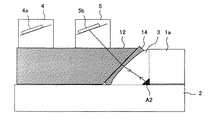
なお、上記一実施形態においては、第2の斜角探触子5は、隅肉溶接部の欠陥で反射され溶接ビード3の外表面から出射された反射波を受信する受信素子5aを有する場合を例にとって説明したが、これに限られない。すなわち、例えば図6に示すように、第2の斜角探触子5は、溶接ビード3の外表面に入射する超音波を送信するとともに、隅肉溶接部の欠陥で反射され溶接ビード3の外表面から出射された反射波を受信する送受信素子5bを有してもよい(又は、送信素子と受信素子とを有してもよい)。そして、探傷制御装置9は、斜角探触子5に超音波の送信指令を出力する送信回路を有し、中央制御装置10は、探傷制御装置28の送信回路26への指令とは異なるタイミングで、探傷制御装置9の送信回路へ指令を出力すればよい。このような変形例では、図6に示すように、例えば隅肉溶接部のルート付近で溶け込み不良A2が生じていた場合に、斜角探触子5から隅肉溶接部に入射された超音波が溶け込み不良A2で反射されて戻って溶接ビード3の外表面から出射され、その反射波が斜角探触子5で受信される。したがって、超音波の伝達経路を比較的短くすることができるため、溶け込み不良A2などが小さい場合でも検出することができる。また、溶接ビード3の外表面からの反射波も受信され、これに基づき溶接ビード3の残肉厚などを演算することも可能である。
In the above embodiment, the
また、上記一実施形態においては、第1の斜角探触子4と第2の斜角探触子5とを別体として構成し、斜角探触子4,5のそれぞれの取付け位置を調整可能な場合を例にとって説明したが、これに限られず、一体化して構成してもよい。また、上記一実施形態においては、第1の斜角探触子4は、1つの送受信素子4aを有する場合を例にとって説明したが、これに限られず、複数の送受信素子を有するアレイ型としてもよい。また、前述の図6で示す変形例においては、第2の斜角探触子5は、1つの送受信素子5bを有する場合を例にとって説明したが、これに限られず、複数の送受信素子を有するアレイ型としてもよい。
In the above-described embodiment, the
例えば図7に示す変形例では、探触子移動装置6のアーム18には、上述した斜角探触子4,5に相当するものとして、多数の送受信素子31aを有するアレイ型探触子31が設けられている。なお、図7では便宜上簡略化して示すが、アレイ型探触子31の送受信素子31aは、上記一実施形態における斜角探触子4の送受信素子4a及び斜角探触子5の受信素子5aのように(前述の図2(b)参照)、二次元配置することが好ましい。そして、素子制御装置32は、複数の送受信素子31aからの球面超音波の送信及び位相をそれぞれ制御するとともに、複数の送受信素子31aでの反射波の受信を制御する。詳細には、複数の送受信素子31aへの電圧印加時間(言い換えれば、遅延時間)をそれぞれ制御して、送受信素子31aから送信する球面超音波33の位相の重ね合わせ位置を制御することにより、干渉波34の角度及び集束を可変制御する。これにより、任意の集束目標点(好ましくは配管2の内表面)及び任意の傾斜角度で干渉波34を送信可能としている。なお、送受信素子31aをシュー12(言い換えれば、配管2)の全周に亘って二次元配置すれば、アレイ型探触子を移動させる移動装置を不要とし、検査時間の短縮化を図ることも可能である。
For example, in the modification shown in FIG. 7, the
1 エルボ(配管継手)
1a ソケット部
2 配管
3 溶接ビード
4 斜角探触子
4a 送受信素子(第1の送信素子、第2の受信素子)
5 斜角探触子
5a 受信素子(第1の受信素子)
5b 送受信素子(第2の送信素子、第1の受信素子)
12 シュー
14 ゲル状接触媒質(ゲル状部材)
31 アレイ型探触子
31a 送受信素子(第1の送信素子、第2の送信素子、第1の受信素子、第2の受信素子)
32 素子制御装置(素子制御手段)
1 Elbow (Piping joint)
DESCRIPTION OF SYMBOLS
5
5b Transceiver element (second transmitter element, first receiver element)
12
31 Array-
32 Element control device (element control means)
Claims (9)
前記配管の非挿入部の外周側に配置されて、非溶接領域である前記配管の外表面に入射する超音波を送信する第1の送信素子と、
前記配管の非挿入部の外周側に配置されて、前記隅肉溶接部の欠陥で反射され前記隅肉溶接部の外表面から出射された反射波を受信する第1の受信素子とを有することを特徴とする超音波検査装置。 In an ultrasonic inspection apparatus that inspects a fillet welded portion that joins a socket portion of a pipe joint and a pipe inserted into the socket portion,
A first transmission element that is disposed on the outer peripheral side of the non-insertion portion of the pipe and transmits an ultrasonic wave incident on an outer surface of the pipe that is a non-welding region;
A first receiving element that is disposed on the outer peripheral side of the non-insertion portion of the pipe and receives a reflected wave that is reflected by a defect of the fillet welded portion and emitted from the outer surface of the fillet welded portion. Ultrasonic inspection apparatus characterized by.
Priority Applications (1)
| Application Number | Priority Date | Filing Date | Title |
|---|---|---|---|
| JP2008204223A JP5292012B2 (en) | 2008-08-07 | 2008-08-07 | Ultrasonic inspection equipment |
Applications Claiming Priority (1)
| Application Number | Priority Date | Filing Date | Title |
|---|---|---|---|
| JP2008204223A JP5292012B2 (en) | 2008-08-07 | 2008-08-07 | Ultrasonic inspection equipment |
Publications (2)
| Publication Number | Publication Date |
|---|---|
| JP2010038820A true JP2010038820A (en) | 2010-02-18 |
| JP5292012B2 JP5292012B2 (en) | 2013-09-18 |
Family
ID=42011522
Family Applications (1)
| Application Number | Title | Priority Date | Filing Date |
|---|---|---|---|
| JP2008204223A Active JP5292012B2 (en) | 2008-08-07 | 2008-08-07 | Ultrasonic inspection equipment |
Country Status (1)
| Country | Link |
|---|---|
| JP (1) | JP5292012B2 (en) |
Cited By (4)
| Publication number | Priority date | Publication date | Assignee | Title |
|---|---|---|---|---|
| CN101943679A (en) * | 2010-08-25 | 2011-01-12 | 无锡华光锅炉股份有限公司 | Short-pipe radial fillet weld ultrasonic flaw detection method |
| JP2012037505A (en) * | 2010-07-15 | 2012-02-23 | Mitsubishi Heavy Ind Ltd | Flaw detector |
| CN108445076A (en) * | 2017-12-29 | 2018-08-24 | 渤海造船厂集团有限公司 | One kind being based on T shape fillet weld transversal crack ultrasonic detection methods |
| JP2019045317A (en) * | 2017-09-01 | 2019-03-22 | 日立Geニュークリア・エナジー株式会社 | Ultrasonic probe, ultrasonic flaw detection apparatus and method |
Families Citing this family (1)
| Publication number | Priority date | Publication date | Assignee | Title |
|---|---|---|---|---|
| CN106840053B (en) * | 2017-03-14 | 2020-01-10 | 中车青岛四方机车车辆股份有限公司 | Ultrasonic nondestructive measurement method for fillet weld leg size and internal defects |
Citations (7)
| Publication number | Priority date | Publication date | Assignee | Title |
|---|---|---|---|---|
| JPS57169673A (en) * | 1981-04-13 | 1982-10-19 | Ishikawajima Harima Heavy Ind Co Ltd | Two probe flaw detection method for piping |
| JPS6379060A (en) * | 1986-09-24 | 1988-04-09 | Mitsubishi Heavy Ind Ltd | Method for ultrasonic flaw detection of fillet welded part |
| JPH11281628A (en) * | 1998-03-30 | 1999-10-15 | Babcock Hitachi Kk | Evaluation apparatus for crack in weld of object to be inspected and probe |
| JP2000097919A (en) * | 1998-09-25 | 2000-04-07 | Hitachi Ltd | Ultrasonic flaw detection method |
| JP2004264122A (en) * | 2003-02-28 | 2004-09-24 | Tokyo Electric Power Co Inc:The | Ultrasonic inspection method and ultrasonic inspection tool |
| JP2006030218A (en) * | 2005-10-12 | 2006-02-02 | Sumitomo Metal Ind Ltd | Quality inspection method of welded steel pipe welded section |
| JP2007132667A (en) * | 2005-11-08 | 2007-05-31 | Hitachi Eng Co Ltd | Non-destructive inspection device of piping welded part |
-
2008
- 2008-08-07 JP JP2008204223A patent/JP5292012B2/en active Active
Patent Citations (7)
| Publication number | Priority date | Publication date | Assignee | Title |
|---|---|---|---|---|
| JPS57169673A (en) * | 1981-04-13 | 1982-10-19 | Ishikawajima Harima Heavy Ind Co Ltd | Two probe flaw detection method for piping |
| JPS6379060A (en) * | 1986-09-24 | 1988-04-09 | Mitsubishi Heavy Ind Ltd | Method for ultrasonic flaw detection of fillet welded part |
| JPH11281628A (en) * | 1998-03-30 | 1999-10-15 | Babcock Hitachi Kk | Evaluation apparatus for crack in weld of object to be inspected and probe |
| JP2000097919A (en) * | 1998-09-25 | 2000-04-07 | Hitachi Ltd | Ultrasonic flaw detection method |
| JP2004264122A (en) * | 2003-02-28 | 2004-09-24 | Tokyo Electric Power Co Inc:The | Ultrasonic inspection method and ultrasonic inspection tool |
| JP2006030218A (en) * | 2005-10-12 | 2006-02-02 | Sumitomo Metal Ind Ltd | Quality inspection method of welded steel pipe welded section |
| JP2007132667A (en) * | 2005-11-08 | 2007-05-31 | Hitachi Eng Co Ltd | Non-destructive inspection device of piping welded part |
Cited By (6)
| Publication number | Priority date | Publication date | Assignee | Title |
|---|---|---|---|---|
| JP2012037505A (en) * | 2010-07-15 | 2012-02-23 | Mitsubishi Heavy Ind Ltd | Flaw detector |
| CN101943679A (en) * | 2010-08-25 | 2011-01-12 | 无锡华光锅炉股份有限公司 | Short-pipe radial fillet weld ultrasonic flaw detection method |
| CN101943679B (en) * | 2010-08-25 | 2012-10-03 | 无锡华光锅炉股份有限公司 | Short-pipe radial fillet weld ultrasonic flaw detection method |
| JP2019045317A (en) * | 2017-09-01 | 2019-03-22 | 日立Geニュークリア・エナジー株式会社 | Ultrasonic probe, ultrasonic flaw detection apparatus and method |
| US11041831B2 (en) | 2017-09-01 | 2021-06-22 | Hitachi-Ge Nuclear Energy, Ltd. | Ultrasonic probe, ultrasonic flaw detection apparatus and method |
| CN108445076A (en) * | 2017-12-29 | 2018-08-24 | 渤海造船厂集团有限公司 | One kind being based on T shape fillet weld transversal crack ultrasonic detection methods |
Also Published As
| Publication number | Publication date |
|---|---|
| JP5292012B2 (en) | 2013-09-18 |
Similar Documents
| Publication | Publication Date | Title |
|---|---|---|
| JP4832550B2 (en) | Ultrasonic flaw detector | |
| JP4839333B2 (en) | Ultrasonic inspection method and ultrasonic inspection apparatus | |
| WO2009107745A1 (en) | Ultrasonic examination device | |
| JP4709640B2 (en) | Ultrasonic flaw detection method and apparatus | |
| JP5419592B2 (en) | Ultrasonic inspection probe and ultrasonic inspection device | |
| JPH04301797A (en) | Apparatus for ultrasonic non-destructive inspection for slender part having substantially constant cross section | |
| US20150233869A1 (en) | Ultrasonic phased array transducer for the nde inspection of the jet pump riser welds and welded attachments | |
| JP5292012B2 (en) | Ultrasonic inspection equipment | |
| JP5868198B2 (en) | Ultrasonic flaw detection apparatus and ultrasonic flaw detection method for welds | |
| WO2012008144A1 (en) | Ultrasonic flaw detecting apparatus and ultrasonic flaw detecting method | |
| JP6069123B2 (en) | Ultrasonic inspection apparatus and ultrasonic inspection method | |
| JP4792440B2 (en) | Pipe weld inspection system | |
| JP5721615B2 (en) | Ultrasonic flaw detector for pipe welds | |
| JP5574731B2 (en) | Ultrasonic flaw detection test method | |
| US9213019B2 (en) | Method of determining a size of a defect using an ultrasonic linear phased array | |
| JP4357265B2 (en) | Ultrasonic flaw detector and ultrasonic flaw detector method | |
| JP2011237234A (en) | Phased-array ultrasonic inspection device, and inspection method and coke drum using the phased-array ultrasonic inspection device | |
| JP2008076129A (en) | Ultrasonic inspection method and ultrasonic inspection device | |
| JP2002214204A (en) | Ultrasonic flaw detector and method using the same | |
| JP5959677B2 (en) | Ultrasonic flaw detection apparatus and ultrasonic flaw detection method | |
| JP2008286639A (en) | Coupling check method of ultrasonic oblique angle flaw detector | |
| JP2018136252A (en) | Ultrasonic inspection device, ultrasonic inspection system including the same, and ultrasonic inspection method and program | |
| JP2012063325A (en) | Laser ultrasonic inspection device and laser ultrasonic inspection method | |
| JP2016191572A (en) | Ultrasonic inspection device | |
| JP3754669B2 (en) | Ultrasonic flaw detection apparatus and ultrasonic flaw detection method |
Legal Events
| Date | Code | Title | Description |
|---|---|---|---|
| A621 | Written request for application examination |
Free format text: JAPANESE INTERMEDIATE CODE: A621 Effective date: 20100519 |
|
| A977 | Report on retrieval |
Free format text: JAPANESE INTERMEDIATE CODE: A971007 Effective date: 20120131 |
|
| A131 | Notification of reasons for refusal |
Free format text: JAPANESE INTERMEDIATE CODE: A131 Effective date: 20120321 |
|
| A521 | Written amendment |
Free format text: JAPANESE INTERMEDIATE CODE: A523 Effective date: 20120515 |
|
| A131 | Notification of reasons for refusal |
Free format text: JAPANESE INTERMEDIATE CODE: A131 Effective date: 20121113 |
|
| A521 | Written amendment |
Free format text: JAPANESE INTERMEDIATE CODE: A523 Effective date: 20121207 |
|
| TRDD | Decision of grant or rejection written | ||
| A01 | Written decision to grant a patent or to grant a registration (utility model) |
Free format text: JAPANESE INTERMEDIATE CODE: A01 Effective date: 20130604 |
|
| A61 | First payment of annual fees (during grant procedure) |
Free format text: JAPANESE INTERMEDIATE CODE: A61 Effective date: 20130610 |
|
| R150 | Certificate of patent or registration of utility model |
Ref document number: 5292012 Country of ref document: JP Free format text: JAPANESE INTERMEDIATE CODE: R150 |