JP2010037597A - Carbon potential operational equipment - Google Patents
Carbon potential operational equipment Download PDFInfo
- Publication number
- JP2010037597A JP2010037597A JP2008202020A JP2008202020A JP2010037597A JP 2010037597 A JP2010037597 A JP 2010037597A JP 2008202020 A JP2008202020 A JP 2008202020A JP 2008202020 A JP2008202020 A JP 2008202020A JP 2010037597 A JP2010037597 A JP 2010037597A
- Authority
- JP
- Japan
- Prior art keywords
- concentration
- value
- carbon potential
- calculated
- upper limit
- Prior art date
- Legal status (The legal status is an assumption and is not a legal conclusion. Google has not performed a legal analysis and makes no representation as to the accuracy of the status listed.)
- Granted
Links
Images


Landscapes
- Solid-Phase Diffusion Into Metallic Material Surfaces (AREA)
Abstract
Description
本発明は、例えば浸炭炉や浸炭窒化炉などの熱処理炉内のCO2 濃度やO2 濃度に基づき炉内雰囲気のカーボンポテンシャル(Carbon Potential:CP)を演算するカーボンポテンシャル演算装置に関するものである。 The present invention relates to a carbon potential calculation device that calculates a carbon potential (Carbon Potential: CP) of an atmosphere in a furnace based on a CO 2 concentration or an O 2 concentration in a heat treatment furnace such as a carburizing furnace or a carbonitriding furnace.
従来より、調質処理を施した鋼材は、強度と靱性との組合せの点で著しく優れているが、耐摩耗性は浸炭焼入れ処理したものに比較して劣り、また繰返し応力による疲労破壊が問題となる部品では疲労亀裂が表面近傍から生ずる関係上、表面における強度が重要となる。そこで、このような観点から、通常、耐摩耗性や疲労破壊に対する強度が必要な品物に対する表面硬化処理として、ガス浸炭法が知られている。 Conventionally, tempered steel is remarkably superior in terms of the combination of strength and toughness, but its wear resistance is inferior to that of carburized and quenched, and fatigue failure due to repeated stress is a problem. In such a component, the strength at the surface is important because fatigue cracks are generated near the surface. Therefore, from this point of view, a gas carburizing method is generally known as a surface hardening treatment for an article that requires strength against wear resistance and fatigue fracture.
このガス浸炭法とは、大規模生産に適した方法であり、LPGなど炭化水素系のガスを変成炉を介して吸熱型変成ガス(触媒により吸熱反応によって変成したガス)に変え浸炭炉に導入する方法である。この吸熱型変成ガスは「キャリアガス」と呼ばれ、例えばH2 ,CO,CH4 ,CO2 ,O2 ,H2 Oなどを含む混合ガスからなっている。浸炭反応は、各ガスの分圧に基づく平衡定数によって支配され、相互に関連を保ちながら釣合の状態にあるため、特定のガス(例えばH2 O,CO2 ,O2 のうちの何れか)の分圧をモニタし、常にある特定の値を維持するように浸炭ガスの流量をコントロールすれば、反応を一方向に進行させることができる。なお、カーボンポテンシャル(Carbon Potential、以下「CP」と略称する)とは、このようなコントロール状態にあるときの浸炭能力を示すものである。 This gas carburizing method is suitable for large-scale production. LPG and other hydrocarbon gases are converted into endothermic gas (gas transformed by an endothermic reaction using a catalyst) via a shift furnace and introduced into the carburizing furnace. It is a method to do. This endothermic modified gas is called a “carrier gas” and is composed of a mixed gas containing, for example, H 2 , CO, CH 4 , CO 2 , O 2 , H 2 O and the like. Since the carburization reaction is governed by an equilibrium constant based on the partial pressure of each gas and is in a balanced state while maintaining mutual relation, any one of specific gases (for example, H 2 O, CO 2 , O 2 ). If the flow rate of the carburizing gas is controlled so as to always maintain a specific value, the reaction can proceed in one direction. The carbon potential (hereinafter abbreviated as “CP”) indicates the carburizing ability in such a controlled state.
また、炉気全体としては平衡関係が成立していても、鋼材表面では流れが不十分などの理由で平衡にズレを生じやすく、分解したCがすべて吸着されるわけではないため、一部はスーティングを起こして「すす」になることがある。このような状態を改善して浸炭能力を増すために、「エンリッチガス」と呼ばれるプロパンなどの生ガスが、0.5〜1%程度直接炉内に添加される。なお、浸炭処理としては、上述したガス浸炭法の他、滴注式浸炭法、液体浸炭法、固体浸炭法、真空浸炭法、プラズマ浸炭法などがある。 In addition, even if an equilibrium relationship is established for the entire furnace air, the steel surface tends to be misaligned due to insufficient flow, etc., and not all of the decomposed C is adsorbed. May cause sooting to become soot. In order to improve such a state and increase the carburizing capacity, a raw gas such as propane called “enrich gas” is directly added to the furnace by about 0.5 to 1%. In addition to the gas carburizing method described above, there are a carburizing method, a liquid carburizing method, a solid carburizing method, a vacuum carburizing method, a plasma carburizing method, and the like.
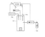
図7は、ガス浸炭法の実施例として下記特許文献1に開示される浸炭炉の概略構成図である。図示のように、下記特許文献1のガス浸炭方法は、浸炭炉101内雰囲気ガスをサンプリングして炉外において炉内雰囲気ガス中のCO2 濃度を検出するCO2 センサ102と、炉内において炉内雰囲気ガス中の酸素濃度を検出する酸素センサ103とを設ける。エンリッチガス104の導入は炉内温度Tの昇温中に開始し、CO2 濃度を基に算出した見掛け上のカーボンポテンシャルCP1 と、酸素濃度を基に算出した見掛け上のカーボンポテンシャルCP2 との差(CP2 −CP1 )を求め、差(CP2 −CP1 )が所定値に近づくようにエンリッチガス104の流量を調整する。
FIG. 7 is a schematic configuration diagram of a carburizing furnace disclosed in Patent Document 1 below as an example of the gas carburizing method. As shown in the figure, the gas carburizing method of Patent Document 1 below includes a CO 2 sensor 102 that samples the atmospheric gas in the
また、特許文献1では浸炭炉及び各種センサによってエンリッチガスのPID制御を行うシステム構成であるが、このような浸炭炉の駆動制御を行うため、浸炭炉に配設されたCO2 センサやO2 センサで測定したCO2 濃度やO2 濃度に基づいて炉内雰囲気のCP値を算出するカーボンポテンシャル演算装置も知られている。
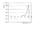
ところで、従来のカーボンポテンシャル演算装置において、例えば温度:1000℃、CO濃度:20%(何れも固定値)を条件としたとき、O2 センサからのO2 濃度に基づくCP値を演算すると図8に示すようなグラフとなる。図示のように、O2 センサからの入力であるO2 濃度を示すEMF(electrmotive force:起電力)が上昇するに連れてCP値が徐々上昇しているが、計算式上、CP値の出力上限値(図ではCP値=1.68%)を超えると、EMFの入力値が上昇してもCP値が下降する特性になっている。 Incidentally, in the conventional carbon potential computing device, such as temperature: 1000 ° C., CO concentration of 20%, as a condition (both fixed values), Fig. 8 when calculating the CP value based on the O 2 concentration from the O 2 sensor It becomes a graph as shown in. As shown in the figure, the CP value gradually increases as the EMF (electrmotive force) indicating the O 2 concentration, which is the input from the O 2 sensor, increases. If the upper limit value (CP value = 1.68% in the figure) is exceeded, the CP value decreases even if the EMF input value increases.
そこで、従来のカーボンポテンシャル演算装置では、O2 濃度に基づくCP値が出力上限値を超えた場合は、図9に示すようにCP値の上限であるCP値=2.0%まで一気に上昇させ、これ以降、EMFの入力値が上昇した場合でも一律でCP値=2.0%と規定した処理を行っている。 Therefore, in the conventional carbon potential calculation device, when the CP value based on the O 2 concentration exceeds the output upper limit value, as shown in FIG. 9, the CP value is increased to 2.0%, which is the upper limit of the CP value. Thereafter, even when the input value of the EMF rises, the process of uniformly defining the CP value = 2.0% is performed.
しかしながら、このようにCP値の出力が上限値を超えたときにCP値を一律で2.0%として処理した場合、CP値が出力上限値を超えた状態(例えばCP値=1.68%以上)で装置を使用するようなときに入力値の急変により測定制御に乱れが生じ、正確なCP値制御が安定して行えないという問題があった。 However, when the CP value is uniformly treated as 2.0% when the output of the CP value exceeds the upper limit value, the CP value exceeds the output upper limit value (for example, CP value = 1.68%). As described above, when the apparatus is used, there is a problem that measurement control is disturbed due to a sudden change in input value, and accurate CP value control cannot be stably performed.
そこで、本発明は上記問題点に鑑みてなされたものであり、O2 濃度に基づき算出されたCP値の出力上限値を超えた場合であっても、安定したCP値制御が行えるカーボンポテンシャル演算装置を提供することを目的とするものである。 Therefore, the present invention has been made in view of the above problems, and even if the output upper limit value of the CP value calculated based on the O 2 concentration is exceeded, the carbon potential calculation capable of performing stable CP value control. The object is to provide an apparatus.
上記した目的を達成するために、請求項1記載のカーボンポテンシャル演算装置は、熱処理炉に設置されたセンサ部によって検出された炉内雰囲気中のO2 濃度、CO濃度、温度に基づき前記炉内雰囲気のカーボンポテンシャルを算出するカーボンポテンシャル演算装置であって、
前記センサ部で検出する前記O2 濃度の入力上限値を設定する設定部と、
前記算出したカーボンポテンシャルが出力上限値を超えた場合に、前記設定部で設定されたO2 濃度の入力上限値に基づき前記算出したカーボンポテンシャルの比例演算を行う演算部と、
を備えたことを特徴とする。
In order to achieve the above object, the carbon potential calculation device according to claim 1 is based on the O 2 concentration, CO concentration, and temperature in the furnace atmosphere detected by a sensor unit installed in the heat treatment furnace. A carbon potential calculation device for calculating the carbon potential of an atmosphere,
A setting unit for setting an input upper limit value of the O 2 concentration detected by the sensor unit;
When the calculated carbon potential exceeds the output upper limit value, a calculation unit that performs a proportional calculation of the calculated carbon potential based on the input upper limit value of the O 2 concentration set by the setting unit;
It is provided with.
請求項2記載のカーボンポテンシャル演算装置は、熱処理炉に設置されたセンサ部によって検出された炉内雰囲気中のO2 濃度、CO濃度、温度に基づき前記炉内雰囲気のカーボンポテンシャルを算出するカーボンポテンシャル演算装置であって、
前記CO濃度を前記炉内雰囲気中のO2 濃度から算出される酸素分圧の平方根で除算したものに下記数3を用いて算出したオーステナイトの飽和炭素量を積算して得られる値が2.7622以上のときに、下記数4を用いて前記カーボンポテンシャルを算出する演算部を備えたことを特徴とする。
A value obtained by integrating the saturated carbon content of austenite calculated by using the following equation 3 to the value obtained by dividing the CO concentration by the square root of the oxygen partial pressure calculated from the O 2 concentration in the furnace atmosphere is 2. An arithmetic unit for calculating the carbon potential using the following Equation 4 when the number is 7622 or more is provided.
請求項3記載のカーボンポテンシャル演算装置は、請求項1又は2記載のカーボンポテンシャル演算装置において、前記設定部からの設定に応じて、前記演算部で算出されたO2 濃度、CO濃度、温度に基づくカーボンポテンシャルと、同じく前記演算部で算出されたCO2 濃度、CO濃度、温度に基づくカーボンポテンシャルとを同時に表示する表示部を備えたことを特徴とする。 The carbon potential calculation device according to claim 3 is the carbon potential calculation device according to claim 1 or 2, wherein the O 2 concentration, the CO concentration, and the temperature calculated by the calculation unit are set according to the setting from the setting unit. And a display unit for simultaneously displaying the carbon potential based on the CO 2 concentration, the CO concentration calculated based on the calculation unit, and the carbon potential based on the temperature.
本発明のカーボンポテンシャル演算装置によれば、O2 濃度に基づき算出したCP値が出力上限値を超えた場合であってもCP値の上限値までの間が比例演算されているため、測定制御が乱れることなく安定したCP値制御を行うことができる。 According to the carbon potential calculation device of the present invention, even when the CP value calculated based on the O 2 concentration exceeds the output upper limit value, the proportional calculation is performed up to the upper limit value of the CP value. Stable CP value control can be performed without disturbance.
以下、本発明を実施するための最良の形態について、添付した図面を参照しながら詳細に説明する。図1は本発明に係るカーボンポテンシャル演算装置の構成を示す概略構成図であり、図2は同装置の前面パネルの概略図であり、図3は同装置においてO2 濃度に基づくCP値演算を説明するための説明図であり、図4は同装置においてCO2 濃度に基づくCP値演算を説明するための説明図であり、図5は同装置においてO2 濃度に基づき算出したCP値の補正したときのEMFとCP値との関係を示すグラフ図であり、図6は同装置においてCO2 濃度に基づき算出したCP値の補正したときのEMFとCP値との関係を示すグラフ図である。 Hereinafter, the best mode for carrying out the present invention will be described in detail with reference to the accompanying drawings. FIG. 1 is a schematic configuration diagram showing a configuration of a carbon potential calculation device according to the present invention, FIG. 2 is a schematic diagram of a front panel of the same device, and FIG. 3 shows a CP value calculation based on O 2 concentration in the same device. FIG. 4 is an explanatory diagram for explaining CP value calculation based on the CO 2 concentration in the apparatus, and FIG. 5 is a correction of the CP value calculated based on the O 2 concentration in the apparatus. FIG. 6 is a graph showing the relationship between the EMF and the CP value when the CP value calculated based on the CO 2 concentration is corrected in the same apparatus. .
まず、本発明に係るカーボンポテンシャル演算装置の構成について、図1、2を参照しながら説明する。 First, the configuration of the carbon potential calculation device according to the present invention will be described with reference to FIGS.
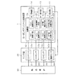
図1に示すように、本例のカーボンポテンシャル演算装置1(以下、CP演算装置と略称する)は、設定部11、演算部12、表示部13、警報部14を備えて構成される。そして、CP演算装置1は、測定対象である例えば浸炭炉や浸炭窒化炉などの熱処理炉30に設置して炉内雰囲気の各種状態を検出するセンサ部20と電気的に接続されている。
As shown in FIG. 1, the carbon potential calculation device 1 (hereinafter abbreviated as CP calculation device) of this example includes a
このセンサ部20は、測定対象となる炉内雰囲気中のCO2 濃度を赤外線吸収法によりCO2 濃度(%)を検出するCO2 センサ21、同じく炉内雰囲気中のCO濃度を赤外線吸収法によりCO濃度(%)を検出するCOセンサ22、炉内雰囲気中のO2 濃度をジルコニア固体電解質の酸素イオン伝導性を利用してO2 濃度をEMF(mV)で検出するO2 センサ23、炉内雰囲気中の温度(℃)を検出する温度センサ24(本例ではK熱電対、R熱電対、S熱電対の3種)などの各種センサで構成され、各センサで検出された検出データを演算部12に出力している。
The
設定部11は、図2に示すように装置の前面パネルの所定箇所に複数設けられた各種キーで構成され、ユーザのキー操作により各種設定が行える。設定内容としては、CO2 センサ21/O2 センサ23の入力切り替え、表示部13に表示する表示内容の切替(例えばCO2 濃度のみ、O2 濃度のみ、CO2 /O2 濃度の同時表示)、O2 濃度/CO2 濃度、CO濃度、温度のうちの1つを固定値とする設定、製造メーカによって異なるCO2 センサ21のスケール上限値の設定、使用する熱電対の選択設定、CP値補正の際に算出されたCP値を真値に近づけるための補正値(傾き補正値、シフト補正値、外部接点補正値)の設定、CP値の比例演算時に用いるEMFの入力上限値設定など、CP値演算に関する各種設定が行える。
As shown in FIG. 2, the
演算部12は、As1演算手段12a、PO2 演算手段12b、As2演算手段12c、CP値演算手段12d、CO2 演算手段12e、定数演算手段12f、CP値補正手段12g、CP値比例演算手段12hとで構成され、センサ部20からの各種検出データ(炉内雰囲気中のCO2 濃度、O2 濃度、CO濃度、温度)に基づくCP値の算出、算出されたCP値の補正、算出されたCP値が出力上限値を超えたときにEMFの入力上限値に基づく比例演算を行っている。
ここで、CP値の演算方法について説明する。CP値の演算では、O2 濃度又はCO2 濃度に基づきCP値を算出する。また、CP値の演算精度を向上させるため、O2 濃度/CO2 濃度、CO濃度、温度のうちの1つの入力値を固定値としている。 Here, a calculation method of the CP value will be described. In the calculation of the CP value, the CP value is calculated based on the O 2 concentration or the CO 2 concentration. In order to improve the calculation accuracy of the CP value, one input value of O 2 concentration / CO 2 concentration, CO concentration, and temperature is set as a fixed value.
まず、O2 濃度、CO濃度(固定値)、温度からCP値を算出する場合、下記数5を用いてAs1(オーステナイトの飽和炭素量)をAs1演算手段12aで算出し、下記数6を用いて測定されたPO2 (酸素分圧)をPO2 演算手段12bで算出し、オーステナイトの飽和炭素量と温度との関係から回帰分析にて得られた下記数7を用いてAs2(オーステナイトの飽和炭素量)をAs2演算手段12cで算出する。
First, when the CP value is calculated from the O 2 concentration, the CO concentration (fixed value), and the temperature, As1 (saturated carbon amount of austenite) is calculated by the As1 calculating
![]()
![]()
そして、上記数6、7で算出したPO2 、As2を用いて下記数8又は9よりCP値演算手段12dでCP値を算出する。なお、数9を用いる場合は、CO濃度(CO)を上記数6で算出した酸素分圧の平方根(PO2 1/2 )で除算したものにオーステナイトの飽和炭素量(As2)を積算して得られる値(L)がL≧2.7622のときに用いる。 Then, the CP value is calculated by the CP value calculating means 12d from the following formula 8 or 9 using PO 2 and As2 calculated by the above formulas 6 and 7. In addition, when Equation 9 is used, the saturation carbon amount (As2) of austenite is added to the value obtained by dividing the CO concentration (CO) by the square root (PO 2 1/2 ) of the oxygen partial pressure calculated in Equation 6 above. Used when the obtained value (L) is L ≧ 2.7622.
また、検出した温度、CO濃度(固定値)、上記数5で算出したAs1と数8又は9で算出したCP値に基づき、下記数10を用いてCO2 演算手段12eでCO2 濃度を算出することもできる。 Further, based on the detected temperature, the CO concentration (fixed value), the As1 calculated by the above Equation 5 and the CP value calculated by the Equation 8 or 9, the CO 2 concentration is calculated by the CO 2 calculating means 12e using the following Equation 10. You can also
次に、CO2 濃度、CO濃度(固定値)、温度からCP値を算出する場合、上記数5を用いてAs1をAs1演算手段12aで算出し、下記数11を用いてK(計算用定数)を定数演算手段12fで算出する。 Next, when calculating the CP value from the CO 2 concentration, CO concentration (fixed value), and temperature, As1 is calculated by the As1 calculating means 12a using the above equation 5, and K (calculation constant) using the following equation 11. ) Is calculated by the constant calculation means 12f.
そして、上記数5、11で算出したAs1、Kを用いて下記数12よりCP演算手段12dでCP値を算出する。
Then, the CP value is calculated by the CP calculating means 12d from the following
なお、O2 濃度、Co濃度、温度に基づくCP値とCO2 濃度、CO濃度、温度に基づくCP値は、入力の設定に応じて個々に算出したり同時に算出することもできる。 Note that the CP value based on the O 2 concentration, the Co concentration, and the temperature and the CP value based on the CO 2 concentration, the CO concentration, and the temperature can be calculated individually or simultaneously according to the input settings.
次に、CP値の補正方法について説明する。上記数5〜12の何れかを用いて算出されたCP値の補正を行う場合、下記数13を用いてCP値補正手段12gで補正を行う。なお、式中のA〜Cは、設定部11にて設定された補正値であり、A:傾き補正値、B:シフト補正値、C:外部接点補正値を示し、外部接点補正値は外部接点信号がONのときのみ加算される。
Next, a CP value correction method will be described. When the CP value calculated using any one of the above formulas 5 to 12 is corrected, the CP
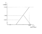
次に、CP値の比例演算について説明する。上記数5〜12の何れかを用いて算出されたCP値の比例演算を行う場合、設定部11にて設定されたEMFの入力上限値に基づきCP値の出力上限値以降のCP値がEMFに比例するようにCP値比例演算手段12hで自動演算する。なお、このとき使用するEMFの入力上限値は、CP値の上限であるCP=2.0のときのEMFの値を示している。
Next, the proportional calculation of the CP value will be described. When the proportional calculation of the CP value calculated using any one of the above formulas 5 to 12 is performed, the CP value after the output upper limit value of the CP value is based on the EMF input upper limit value set by the setting
表示部13は、数値又は文字を複数の7セグメント表示により発光表示する数値表示領域13a、各種設定時や警報部14からの警報出力などに応じて点灯/点滅を行うステータス表示領域13bを備え、図2に示すように機器の前面パネルに設けられている。表示部13は、演算部12で算出されたO2 濃度に基づくCP値とCO2 濃度に基づくCP値の個別表示若しくは同時表示、センサ部20で検出されたCO2 濃度、O2 濃度、CO濃度、温度などを、設定部11による設定内容に応じて表示する。
The
警報部14は、例えばブザーなどの鳴動装置やLEDランプなどの表示装置で構成され、センサ部20との接続が断線した場合、センサ部20から入力する検出データが異常の場合、CP値の演算結果により、|CP値(O2 )−CP値(CO2 )|>偏差設定値(予め設定された任意の値)の場合に外部に異常を通知するための警報出力(鳴動や点灯/点滅など)を行う。
The
次に、上述したCP演算装置1における具体的な実施例について、図3、4を参照しながら説明する。ここでは、実施条件として温度が1000℃、CO濃度が固定値の25%、O2 濃度が1000mV、Co2 濃度が1.0%、設定部11で設定したEMFの入力上限値が1300mVとし、実施例1としてO2 濃度からのCP値算出後の比例演算、実施例2としてCO2 濃度からのCP値算出後の比例演算についてそれぞれ説明する。
Next, a specific embodiment of the above-described CP arithmetic device 1 will be described with reference to FIGS. Here, as an implementation condition, the temperature is 1000 ° C., the CO concentration is 25% of the fixed value, the O 2 concentration is 1000 mV, the Co 2 concentration is 1.0%, and the input upper limit value of the EMF set by the setting
<実施例1>
図3に示すように、まず上記数6を用いてPO2 を算出し(PO2 =2.994E−17)、上記数7を用いてAs2を算出する(As2=1.181E−11)。そして、上記数6、7によって算出されたPO2 、As2に基づき、上記数8を用いてCP値を算出する。(CP=0.081)。
<Example 1>
As shown in FIG. 3, first, PO 2 is calculated using the above equation 6 (PO 2 = 2.994E-17), and As2 is calculated using the above equation 7 (As2 = 1.181E-11). Then, based on PO 2 and As2 calculated by the above formulas 6 and 7, the CP value is calculated by using the above formula 8. (CP = 0.081).
そして、設定部11で設定されたEMFの入力上限値に基づき算出されたCP値をCP値の上限値まで比例するように自動演算することで、図5に示すようなEMFに比例したCP値のグラフとなる。
Then, the CP value calculated based on the input upper limit value of the EMF set by the setting
<実施例2>
図4に示すように、まず上記数5を用いてAs1を算出し(As1=1.579)、上記数11を用いて計算用定数であるKを算出する(K=2.093)。そして、上記数5、11によって算出されたAs1、Kに基づき、上記数12を用いてCP値を算出する(CP=0.080)。
<Example 2>
As shown in FIG. 4, first, As1 is calculated using Equation 5 (As1 = 1.579), and K, which is a calculation constant, is calculated using Equation 11 (K = 2.093). Then, based on As1 and K calculated by the
そして、設定部11で設定されたEMFの入力上限値に基づき算出されたCP値をCP値の上限値まで比例するように自動演算することで、図6に示すようなEMFに比例したCP値のグラフとなる。
Then, by automatically calculating the CP value calculated based on the input upper limit value of the EMF set by the setting
このように、上述したCP演算装置1は、CO2 センサ21からのCO2 濃度若しくはO2 センサ23からのO2 濃度、温度、CO濃度に基づき炉内雰囲気のCP値を算出する。そして、設定部11で設定したEMFの入力上限値に基づき、算出したCP値の出力上限値以降の値をCP値の上限値まで比例するように自動演算する。
Thus, CP computing device 1 described above, O 2 concentration from the CO 2 concentration or O 2 sensor 23 from the CO 2 sensor 21, the temperature, calculates the CP value based furnace atmosphere CO concentration. Then, based on the input upper limit value of the EMF set by the setting
これにより、CP値がCP値の出力上限値を超えた場合であっても、CP値の上限値までの間が比例演算されているため、測定制御が乱れることなく安定したCP値制御を行うことができる。 As a result, even when the CP value exceeds the output upper limit value of the CP value, since the proportional calculation is performed up to the upper limit value of the CP value, stable CP value control is performed without disturbing the measurement control. be able to.
以上、本願発明における最良の形態について説明したが、この形態による記述及び図面により本発明が限定されることはない。すなわち、この形態に基づいて当業者等によりなされる他の形態、実施例及び運用技術等はすべて本発明の範疇に含まれることは勿論である。 As mentioned above, although the best form in this invention was demonstrated, this invention is not limited with the description and drawing by this form. That is, it is a matter of course that all other forms, examples, operation techniques, and the like made by those skilled in the art based on this form are included in the scope of the present invention.
1…カーボンポテンシャル演算装置(CP演算装置)
11…設定部
12…演算部(12a…As1演算手段、12b…PO2 演算手段、12c…As2演算手段、12d…CP値演算手段、12e…Co2 演算手段、12f…定数演算手段、12g…CP値補正手段、12h…CP値比例演算手段)
13…表示部(13a…数値表示領域、13b…ステータス表示領域)
14…警報部
20…センサ部(21…CO2 センサ、22…COセンサ、23…O2 センサ、24…温度センサ)
30…熱処理炉
1 ... Carbon potential computing device (CP computing device)
11 ... setting
13: Display section (13a: Numerical display area, 13b: Status display area)
14 ...
30 ... Heat treatment furnace
Claims (3)
前記センサ部で検出する前記O2 濃度の入力上限値を設定する設定部と、
前記算出したカーボンポテンシャルが出力上限値を超えた場合に、前記設定部で設定されたO2 濃度の入力上限値に基づき前記算出したカーボンポテンシャルの比例演算を行う演算部と、
を備えたことを特徴とするカーボンポテンシャル演算装置。 A carbon potential computing device that calculates the carbon potential of the furnace atmosphere based on the O 2 concentration, CO concentration, and temperature in the furnace atmosphere detected by a sensor unit installed in the heat treatment furnace,
A setting unit for setting an input upper limit value of the O 2 concentration detected by the sensor unit;
When the calculated carbon potential exceeds the output upper limit value, a calculation unit that performs a proportional calculation of the calculated carbon potential based on the input upper limit value of the O 2 concentration set by the setting unit;
A carbon potential calculation device characterized by comprising:
前記CO濃度を前記炉内雰囲気中のO2 濃度から算出される酸素分圧の平方根で除算したものに下記数1を用いて算出したオーステナイトの飽和炭素量を積算して得られる値が2.7622以上のときに、下記数2を用いて前記カーボンポテンシャルを算出する演算部を備えたことを特徴とするカーボンポテンシャル演算装置。
A value obtained by integrating the saturated carbon content of austenite calculated by using the following Equation 1 to the value obtained by dividing the CO concentration by the square root of the oxygen partial pressure calculated from the O 2 concentration in the furnace atmosphere is 2. A carbon potential calculation device comprising a calculation unit for calculating the carbon potential using the following formula 2 when the value is 7622 or more.
Priority Applications (1)
| Application Number | Priority Date | Filing Date | Title |
|---|---|---|---|
| JP2008202020A JP5390139B2 (en) | 2008-08-05 | 2008-08-05 | Carbon potential calculation device |
Applications Claiming Priority (1)
| Application Number | Priority Date | Filing Date | Title |
|---|---|---|---|
| JP2008202020A JP5390139B2 (en) | 2008-08-05 | 2008-08-05 | Carbon potential calculation device |
Publications (2)
| Publication Number | Publication Date |
|---|---|
| JP2010037597A true JP2010037597A (en) | 2010-02-18 |
| JP5390139B2 JP5390139B2 (en) | 2014-01-15 |
Family
ID=42010450
Family Applications (1)
| Application Number | Title | Priority Date | Filing Date |
|---|---|---|---|
| JP2008202020A Active JP5390139B2 (en) | 2008-08-05 | 2008-08-05 | Carbon potential calculation device |
Country Status (1)
| Country | Link |
|---|---|
| JP (1) | JP5390139B2 (en) |
Cited By (1)
| Publication number | Priority date | Publication date | Assignee | Title |
|---|---|---|---|---|
| JP2016151517A (en) * | 2015-02-18 | 2016-08-22 | 新栄熱計装株式会社 | Carbon potential calculation device |
Citations (10)
| Publication number | Priority date | Publication date | Assignee | Title |
|---|---|---|---|---|
| JPS5036305A (en) * | 1973-08-02 | 1975-04-05 | ||
| JPS54132442A (en) * | 1978-03-21 | 1979-10-15 | Ipsen Ind Int Gmbh | Method and apparatus for controlling carbon level of mixture gas reacting in furnace chamber |
| JPS5713169A (en) * | 1980-06-24 | 1982-01-23 | Oriental Eng Kk | Method for controlling concentration of carbon in carburizing atmosphere |
| JPS57177969A (en) * | 1981-04-23 | 1982-11-01 | Chugai Ro Kogyo Kaisha Ltd | Controlling method for carbon potential in furnace |
| JPS62227074A (en) * | 1986-03-28 | 1987-10-06 | Osaka Gas Co Ltd | Method for controlling flow rate of enriching gas in gas carburizing process |
| JPS62243754A (en) * | 1986-04-15 | 1987-10-24 | Isuzu Motors Ltd | Control device for carburization furnace atmosphere |
| JPH02195255A (en) * | 1989-01-25 | 1990-08-01 | Ngk Insulators Ltd | Apparatus for measuring carbon potential in furnace atmosphere in reduction atmosphere furnace |
| JPH03193863A (en) * | 1989-12-22 | 1991-08-23 | Koyo Rindobaagu Kk | Continuous type gas carburization furnace |
| JP2000328224A (en) * | 1999-05-24 | 2000-11-28 | Toho Gas Co Ltd | Gas carburization method |
| JP2003247056A (en) * | 2003-01-20 | 2003-09-05 | Dowa Mining Co Ltd | Method and system for controlling atmosphere in heat treatment furnace |
-
2008
- 2008-08-05 JP JP2008202020A patent/JP5390139B2/en active Active
Patent Citations (10)
| Publication number | Priority date | Publication date | Assignee | Title |
|---|---|---|---|---|
| JPS5036305A (en) * | 1973-08-02 | 1975-04-05 | ||
| JPS54132442A (en) * | 1978-03-21 | 1979-10-15 | Ipsen Ind Int Gmbh | Method and apparatus for controlling carbon level of mixture gas reacting in furnace chamber |
| JPS5713169A (en) * | 1980-06-24 | 1982-01-23 | Oriental Eng Kk | Method for controlling concentration of carbon in carburizing atmosphere |
| JPS57177969A (en) * | 1981-04-23 | 1982-11-01 | Chugai Ro Kogyo Kaisha Ltd | Controlling method for carbon potential in furnace |
| JPS62227074A (en) * | 1986-03-28 | 1987-10-06 | Osaka Gas Co Ltd | Method for controlling flow rate of enriching gas in gas carburizing process |
| JPS62243754A (en) * | 1986-04-15 | 1987-10-24 | Isuzu Motors Ltd | Control device for carburization furnace atmosphere |
| JPH02195255A (en) * | 1989-01-25 | 1990-08-01 | Ngk Insulators Ltd | Apparatus for measuring carbon potential in furnace atmosphere in reduction atmosphere furnace |
| JPH03193863A (en) * | 1989-12-22 | 1991-08-23 | Koyo Rindobaagu Kk | Continuous type gas carburization furnace |
| JP2000328224A (en) * | 1999-05-24 | 2000-11-28 | Toho Gas Co Ltd | Gas carburization method |
| JP2003247056A (en) * | 2003-01-20 | 2003-09-05 | Dowa Mining Co Ltd | Method and system for controlling atmosphere in heat treatment furnace |
Cited By (1)
| Publication number | Priority date | Publication date | Assignee | Title |
|---|---|---|---|---|
| JP2016151517A (en) * | 2015-02-18 | 2016-08-22 | 新栄熱計装株式会社 | Carbon potential calculation device |
Also Published As
| Publication number | Publication date |
|---|---|
| JP5390139B2 (en) | 2014-01-15 |
Similar Documents
| Publication | Publication Date | Title |
|---|---|---|
| EP2835431B1 (en) | Heat treatment apparatus | |
| US6591215B1 (en) | Systems and methods for controlling the activity of carbon in heat treating atmospheres | |
| JP2002212702A (en) | Carburizing method and carburizing equipment | |
| KR101028538B1 (en) | A system for controlling atmosphere gas inside furnace | |
| CN1841059B (en) | Method of checking the function of a sensor | |
| US6612154B1 (en) | Systems and methods for monitoring or controlling the ratio of hydrogen to water vapor in metal heat treating atmospheres | |
| CA2785711C (en) | Control of the converter process by means of exhaust gas signals | |
| JP5390139B2 (en) | Carbon potential calculation device | |
| JP2013185884A (en) | Water quality analyzer | |
| JP2013033016A (en) | Device and method for measuring oxygen diffusion coefficient | |
| JPWO2014167982A1 (en) | Correction device, correction method, and steel refining method | |
| JP3973795B2 (en) | Gas carburizing method | |
| WO2021075389A1 (en) | Heat treatment furnace, control method for same, information processing device, information processing method, and program | |
| JPH0645867B2 (en) | Atmosphere heat treatment control device | |
| JP2592517B2 (en) | Apparatus for measuring carbon potential in furnace air in reducing atmosphere furnace | |
| EP0859067B1 (en) | Method and apparatus for controlling the atmosphere in a heat treatment furnace | |
| US10928287B2 (en) | Method and apparatus for using a gas density sensor to measure and control gas mixture composition | |
| JP2016151517A (en) | Carbon potential calculation device | |
| JPS62243754A (en) | Control device for carburization furnace atmosphere | |
| US6941828B2 (en) | Process as well as device for measuring a component amount released during a thermo-chemical treatment of metallic work piece from the gaseous atmosphere | |
| US10816524B2 (en) | Method for calculating amount of ammonia in gas sample | |
| KR20140002255A (en) | The method of analyzing carbon content | |
| JP2575507B2 (en) | Furnace operation method of reducing atmosphere furnace | |
| JP2572788B2 (en) | Control method of heat treatment atmosphere | |
| US20170292170A1 (en) | Controlling and optimising furnace atmospheres for stainless steel heat treatment |
Legal Events
| Date | Code | Title | Description |
|---|---|---|---|
| A621 | Written request for application examination |
Free format text: JAPANESE INTERMEDIATE CODE: A621 Effective date: 20110613 |
|
| A977 | Report on retrieval |
Free format text: JAPANESE INTERMEDIATE CODE: A971007 Effective date: 20130612 |
|
| A131 | Notification of reasons for refusal |
Free format text: JAPANESE INTERMEDIATE CODE: A131 Effective date: 20130625 |
|
| A521 | Request for written amendment filed |
Free format text: JAPANESE INTERMEDIATE CODE: A523 Effective date: 20130826 |
|
| TRDD | Decision of grant or rejection written | ||
| A01 | Written decision to grant a patent or to grant a registration (utility model) |
Free format text: JAPANESE INTERMEDIATE CODE: A01 Effective date: 20130917 |
|
| A61 | First payment of annual fees (during grant procedure) |
Free format text: JAPANESE INTERMEDIATE CODE: A61 Effective date: 20131010 |
|
| R150 | Certificate of patent or registration of utility model |
Ref document number: 5390139 Country of ref document: JP Free format text: JAPANESE INTERMEDIATE CODE: R150 Free format text: JAPANESE INTERMEDIATE CODE: R150 |
|
| R250 | Receipt of annual fees |
Free format text: JAPANESE INTERMEDIATE CODE: R250 |
|
| R250 | Receipt of annual fees |
Free format text: JAPANESE INTERMEDIATE CODE: R250 |
|
| R250 | Receipt of annual fees |
Free format text: JAPANESE INTERMEDIATE CODE: R250 |
|
| R250 | Receipt of annual fees |
Free format text: JAPANESE INTERMEDIATE CODE: R250 |
|
| R250 | Receipt of annual fees |
Free format text: JAPANESE INTERMEDIATE CODE: R250 |
|
| R250 | Receipt of annual fees |
Free format text: JAPANESE INTERMEDIATE CODE: R250 |
|
| R250 | Receipt of annual fees |
Free format text: JAPANESE INTERMEDIATE CODE: R250 |
|
| R250 | Receipt of annual fees |
Free format text: JAPANESE INTERMEDIATE CODE: R250 |