JP2010031875A - 燃料噴射システムに関連する装置および方法 - Google Patents
燃料噴射システムに関連する装置および方法 Download PDFInfo
- Publication number
- JP2010031875A JP2010031875A JP2009255711A JP2009255711A JP2010031875A JP 2010031875 A JP2010031875 A JP 2010031875A JP 2009255711 A JP2009255711 A JP 2009255711A JP 2009255711 A JP2009255711 A JP 2009255711A JP 2010031875 A JP2010031875 A JP 2010031875A
- Authority
- JP
- Japan
- Prior art keywords
- fuel
- pump
- temperature
- conduit
- check valve
- Prior art date
- Legal status (The legal status is an assumption and is not a legal conclusion. Google has not performed a legal analysis and makes no representation as to the accuracy of the status listed.)
- Granted
Links
- 239000000446 fuel Substances 0.000 title claims abstract description 96
- 238000002347 injection Methods 0.000 title claims abstract description 21
- 239000007924 injection Substances 0.000 title claims abstract description 21
- 238000000034 method Methods 0.000 title claims abstract description 14
- 238000004891 communication Methods 0.000 claims abstract description 7
- 239000012530 fluid Substances 0.000 claims abstract description 7
- 238000009529 body temperature measurement Methods 0.000 claims description 6
- 238000005259 measurement Methods 0.000 claims description 6
- 239000000243 solution Substances 0.000 abstract description 4
- 230000007257 malfunction Effects 0.000 description 5
- 239000002828 fuel tank Substances 0.000 description 4
- 238000012546 transfer Methods 0.000 description 4
- 238000002485 combustion reaction Methods 0.000 description 2
- 238000012544 monitoring process Methods 0.000 description 2
- 230000001960 triggered effect Effects 0.000 description 2
- 238000010586 diagram Methods 0.000 description 1
Images
Classifications
-
- F—MECHANICAL ENGINEERING; LIGHTING; HEATING; WEAPONS; BLASTING
- F02—COMBUSTION ENGINES; HOT-GAS OR COMBUSTION-PRODUCT ENGINE PLANTS
- F02M—SUPPLYING COMBUSTION ENGINES IN GENERAL WITH COMBUSTIBLE MIXTURES OR CONSTITUENTS THEREOF
- F02M63/00—Other fuel-injection apparatus having pertinent characteristics not provided for in groups F02M39/00 - F02M57/00 or F02M67/00; Details, component parts, or accessories of fuel-injection apparatus, not provided for in, or of interest apart from, the apparatus of groups F02M39/00 - F02M61/00 or F02M67/00; Combination of fuel pump with other devices, e.g. lubricating oil pump
- F02M63/02—Fuel-injection apparatus having several injectors fed by a common pumping element, or having several pumping elements feeding a common injector; Fuel-injection apparatus having provisions for cutting-out pumps, pumping elements, or injectors; Fuel-injection apparatus having provisions for variably interconnecting pumping elements and injectors alternatively
- F02M63/0225—Fuel-injection apparatus having a common rail feeding several injectors ; Means for varying pressure in common rails; Pumps feeding common rails
-
- F—MECHANICAL ENGINEERING; LIGHTING; HEATING; WEAPONS; BLASTING
- F02—COMBUSTION ENGINES; HOT-GAS OR COMBUSTION-PRODUCT ENGINE PLANTS
- F02M—SUPPLYING COMBUSTION ENGINES IN GENERAL WITH COMBUSTIBLE MIXTURES OR CONSTITUENTS THEREOF
- F02M59/00—Pumps specially adapted for fuel-injection and not provided for in groups F02M39/00 -F02M57/00, e.g. rotary cylinder-block type of pumps
- F02M59/44—Details, components parts, or accessories not provided for in, or of interest apart from, the apparatus of groups F02M59/02 - F02M59/42; Pumps having transducers, e.g. to measure displacement of pump rack or piston
-
- F—MECHANICAL ENGINEERING; LIGHTING; HEATING; WEAPONS; BLASTING
- F02—COMBUSTION ENGINES; HOT-GAS OR COMBUSTION-PRODUCT ENGINE PLANTS
- F02M—SUPPLYING COMBUSTION ENGINES IN GENERAL WITH COMBUSTIBLE MIXTURES OR CONSTITUENTS THEREOF
- F02M63/00—Other fuel-injection apparatus having pertinent characteristics not provided for in groups F02M39/00 - F02M57/00 or F02M67/00; Details, component parts, or accessories of fuel-injection apparatus, not provided for in, or of interest apart from, the apparatus of groups F02M39/00 - F02M61/00 or F02M67/00; Combination of fuel pump with other devices, e.g. lubricating oil pump
-
- F—MECHANICAL ENGINEERING; LIGHTING; HEATING; WEAPONS; BLASTING
- F02—COMBUSTION ENGINES; HOT-GAS OR COMBUSTION-PRODUCT ENGINE PLANTS
- F02D—CONTROLLING COMBUSTION ENGINES
- F02D2200/00—Input parameters for engine control
- F02D2200/02—Input parameters for engine control the parameters being related to the engine
- F02D2200/06—Fuel or fuel supply system parameters
- F02D2200/0602—Fuel pressure
-
- F—MECHANICAL ENGINEERING; LIGHTING; HEATING; WEAPONS; BLASTING
- F02—COMBUSTION ENGINES; HOT-GAS OR COMBUSTION-PRODUCT ENGINE PLANTS
- F02D—CONTROLLING COMBUSTION ENGINES
- F02D41/00—Electrical control of supply of combustible mixture or its constituents
- F02D41/30—Controlling fuel injection
- F02D41/38—Controlling fuel injection of the high pressure type
- F02D41/3809—Common rail control systems
- F02D41/3836—Controlling the fuel pressure
-
- F—MECHANICAL ENGINEERING; LIGHTING; HEATING; WEAPONS; BLASTING
- F02—COMBUSTION ENGINES; HOT-GAS OR COMBUSTION-PRODUCT ENGINE PLANTS
- F02M—SUPPLYING COMBUSTION ENGINES IN GENERAL WITH COMBUSTIBLE MIXTURES OR CONSTITUENTS THEREOF
- F02M2200/00—Details of fuel-injection apparatus, not otherwise provided for
- F02M2200/24—Fuel-injection apparatus with sensors
- F02M2200/248—Temperature sensors
Landscapes
- Engineering & Computer Science (AREA)
- Chemical & Material Sciences (AREA)
- Combustion & Propulsion (AREA)
- Mechanical Engineering (AREA)
- General Engineering & Computer Science (AREA)
- Fuel-Injection Apparatus (AREA)
- Electrical Control Of Air Or Fuel Supplied To Internal-Combustion Engine (AREA)
- Combined Controls Of Internal Combustion Engines (AREA)
Abstract
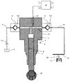
【解決手段】このシステムは、本体部分5にピストン2、ポンプシリンダ6およびポンプ室7か設けられた燃料加圧ポンプ1、ポンプ室7と流体的に連通する燃料流入導管8および燃料流出導管9を有し、導管8,9には、それぞれ逆止弁 8.1,9.1が設けられる。また本体部分5には燃料の温度を検出するための温度測定装置15が設けられる。燃料流出導管9は共通の蓄圧器11に接続され、燃料は高圧でポンプ室7から流出する。このシステムを使用する際、逆止弁 9.1に故障が発生すれば、燃料は逆止弁 9.1を前後に通って多数回加圧されるため、設定値より高温になる。測定された燃料の温度を解析装置16に記憶された設定値と比較するか、または各ポンプの燃料の温度を比較して故障の発生を検出する。
【選択図】図1
Description
2 ピストン装置
3 燃料タンク
4 管路
4.1 移送ポンプ
5 本体部分
6 ポンプシリンダ
7 ポンプ室
8 燃料流入導管
8.1 逆止弁
9 燃料流出導管
9.1 逆止弁
10 燃料移送管路
11 蓄圧器
11′ 管路
12 噴射ノズル
13 燃焼室
14 カム軸
15 温度測定装置
16 解析装置
Claims (4)
- 燃料噴射システムと関連する装置であって、該装置はポンプシリンダ(6)およびポンプ室(7)がポンプの本体部分(5)内に設けられた、燃料加圧ポンプ(1)、およびポンプ室と流体的に連通した燃料流入導管(8)および燃料流出導管(9)を有し、該導管が逆止弁(8.1,9.1)を有し、さらにシリンダ(6)内に設けられたピストン装置(2)を有し、該ピストン装置がその長手方向軸線に沿って移動可能であり、前記装置がさらに前記本体部分(5)に配置された温度測定装置を有する前記装置において、
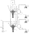
前記装置が、ポンプ燃料を機能的に共通の空間(11,11′)に給送するように設けられた多数の燃料加圧ポンプ(1)を有し、該ポンプがそれぞれ少なくとも一つの温度測定装置(15)を有し、
前記温度測定装置(15)が前記燃料加圧ポンプの温度を測定することにより前記出口導管(9)の逆止弁(9.1)の作動を監視するように設計されていて、および
前記装置は、さらに各燃料加圧ポンプ(1)の各温度測定装置(15)から読出された測定データを比較するための解析装置(16)を有し、該解析装置(16)において各燃料加圧ポンプ(1)の温度が少なくとも一つの他の燃料加圧ポンプ(1)の温度と比較され、もし温度差が設定点を越えるならば、警報手順が起動されることを特徴とする燃料噴射装置と関連する装置。 - 前記温度測定装置(15)がポンプ室(7)またはポンプ室と流出導管の逆止弁を接続する管路(7.1)に隣接してまたは流出導管(9)の逆止弁(9.1)に隣接して設けられることを特徴とする請求項1に記載された装置。
- 燃料噴射システムと関連する方法であって、前記システムは、ポンプシリンダ(6)およびポンプ室(7)がそのポンプ本体部分(5)内に設けられた加圧ポンプ(1)、およびポンプ室と流体的に連通した燃料流入導管(8)および燃料流出導管(9)を有し、該導管が逆止弁(8.1,9.1)を有し、さらにシリンダ(6)内に設けられたピストン装置(2)を有し、前記方法において、燃料がピストン装置の吸込行程の間流入導管(8)の逆止弁(8.1)を通ってポンプ室内に流入し、ピストン装置の出力行程の間流出導管(9)の逆止弁(9.1)を通って高圧および高温でポンプ室から流出し、前記加圧ポンプの温度が温度測定装置によって測定される前記方法において、前記逆止弁(9.1)の作用が前記加圧ポンプの温度を測定することによって監視され、および
前記装置が燃料噴射システムと関連して実施され、該システムが機能的に共通の空間(11,11′)内に給送するため設けられた多数の燃料圧力加圧ポンプ(1)を含み、そのポンプは、それぞれ少なくとも一つの温度測定装置(15)が設けられ、前記燃料噴射装置がさらに各燃料加圧ポンプ(1)の各温度測定装置(15)から読出された測定データを比較するための解析装置(16)を有し、前記方法において各燃料加圧ポンプ(1)の温度が解析装置(16)に読込まれ、該解析装置(16)において各燃料加圧ポンプ(1)の温度が少なくとも一つの他の燃料加圧ポンプ(1)の温度と比較され、もし温度差が設定点を越えるならば、警報手順が起動される
ことを特徴とする燃料噴射装置と関連する方法。 - 各燃料加圧ポンプ(1)の温度は燃料噴射システムが作用しているとき定期的に読出されることを特徴とする請求項3に記載された方法。
Applications Claiming Priority (2)
| Application Number | Priority Date | Filing Date | Title |
|---|---|---|---|
| FI20021841 | 2002-10-16 | ||
| FI20021841A FI117350B (fi) | 2002-10-16 | 2002-10-16 | Laitteisto ja menetelmä polttoaineen syöttöjärjestelmän yhteydessä |
Related Parent Applications (1)
| Application Number | Title | Priority Date | Filing Date |
|---|---|---|---|
| JP2003355068A Division JP4464652B2 (ja) | 2002-10-16 | 2003-10-15 | 燃料噴射システムに関連する装置および方法 |
Publications (2)
| Publication Number | Publication Date |
|---|---|
| JP2010031875A true JP2010031875A (ja) | 2010-02-12 |
| JP4966365B2 JP4966365B2 (ja) | 2012-07-04 |
Family
ID=8564765
Family Applications (2)
| Application Number | Title | Priority Date | Filing Date |
|---|---|---|---|
| JP2003355068A Expired - Lifetime JP4464652B2 (ja) | 2002-10-16 | 2003-10-15 | 燃料噴射システムに関連する装置および方法 |
| JP2009255711A Expired - Lifetime JP4966365B2 (ja) | 2002-10-16 | 2009-11-09 | 燃料噴射システムに関連する装置および方法 |
Family Applications Before (1)
| Application Number | Title | Priority Date | Filing Date |
|---|---|---|---|
| JP2003355068A Expired - Lifetime JP4464652B2 (ja) | 2002-10-16 | 2003-10-15 | 燃料噴射システムに関連する装置および方法 |
Country Status (6)
| Country | Link |
|---|---|
| US (1) | US6845752B2 (ja) |
| EP (1) | EP1411240B1 (ja) |
| JP (2) | JP4464652B2 (ja) |
| AT (1) | ATE314576T1 (ja) |
| DE (1) | DE60302976T2 (ja) |
| FI (1) | FI117350B (ja) |
Families Citing this family (5)
| Publication number | Priority date | Publication date | Assignee | Title |
|---|---|---|---|---|
| FI117350B (fi) * | 2002-10-16 | 2006-09-15 | Waertsilae Finland Oy | Laitteisto ja menetelmä polttoaineen syöttöjärjestelmän yhteydessä |
| SE530565C2 (sv) | 2006-11-10 | 2008-07-08 | Scania Cv Ab | Bränslepumpanordning |
| DE102007044001B4 (de) * | 2007-09-14 | 2019-08-01 | Robert Bosch Gmbh | Verfahren zur Steuerung eines Kraftstoffeinspritzsystems einer Brennkraftmaschine |
| EP2287462B1 (en) | 2009-07-08 | 2012-04-18 | Delphi Technologies Holding S.à.r.l. | A pump unit |
| DE102011082704A1 (de) * | 2011-09-14 | 2013-03-14 | Robert Bosch Gmbh | Kraftstoffhochdruckpumpe für ein Einspritzsystem |
Citations (6)
| Publication number | Priority date | Publication date | Assignee | Title |
|---|---|---|---|---|
| JPH11166445A (ja) * | 1997-12-04 | 1999-06-22 | Yamaha Motor Co Ltd | エンジンの異常燃焼制御方法 |
| JP2000265896A (ja) * | 1999-03-17 | 2000-09-26 | Toyota Motor Corp | 高圧燃料噴射装置の異常判定方法 |
| WO2001007779A1 (en) * | 1999-07-23 | 2001-02-01 | Hitachi, Ltd. | High-pressure fuel pump and fuel feed method |
| JP2002235633A (ja) * | 2001-02-08 | 2002-08-23 | Denso Corp | 分配型燃料噴射ポンプ |
| JP2003222060A (ja) * | 2001-12-03 | 2003-08-08 | Robert Bosch Gmbh | 内燃機関の駆動方法、コンピュータプログラム、開制御および閉ループ制御装置、および内燃機関 |
| JP2004138063A (ja) * | 2002-10-16 | 2004-05-13 | Waertsilae Finland Oy | 燃料噴射システムに関連する装置および方法 |
Family Cites Families (13)
| Publication number | Priority date | Publication date | Assignee | Title |
|---|---|---|---|---|
| JPS58133440A (ja) * | 1982-02-03 | 1983-08-09 | Nissan Motor Co Ltd | 電子制御式燃料噴射ポンプ |
| JPS61212661A (ja) * | 1985-03-19 | 1986-09-20 | Nippon Denso Co Ltd | 分配型燃料噴射ポンプ |
| DE3602713A1 (de) * | 1986-01-30 | 1987-08-06 | Bosch Gmbh Robert | Kraftstoffeinspritzpumpe fuer brennkraftmaschinen |
| DE3739198C1 (de) * | 1987-11-19 | 1989-05-03 | Bosch Gmbh Robert | Kraftstoffeinspritzpumpe fuer Brennkraftmaschinen |
| US6102000A (en) * | 1993-11-02 | 2000-08-15 | Toyota Jidosha Kabushiki Kaisha | Fuel injection apparatus for engine |
| US5509392A (en) * | 1995-04-28 | 1996-04-23 | Schmitz; John J. | Anti-vapor lock fuel system |
| JP3744036B2 (ja) * | 1995-10-31 | 2006-02-08 | 日産自動車株式会社 | ディーゼルエンジンの燃料性状検出装置および制御装置 |
| US5868175A (en) * | 1996-06-28 | 1999-02-09 | Franklin Electric Co., Inc. | Apparatus for recovery of fuel vapor |
| DE19746563A1 (de) * | 1997-10-22 | 1999-04-29 | Bosch Gmbh Robert | Kraftstoffeinspritzeinrichtung für Brennkraftmaschinen |
| FI107831B (fi) | 1998-05-20 | 2001-10-15 | Waertsilae Tech Oy Ab | Polttoaineensyöttöjärjestelmä |
| DE19957742A1 (de) * | 1999-12-01 | 2001-06-07 | Bosch Gmbh Robert | Kraftstoffzuführvorrichtung für einen Verbrennungsmotor |
| DE10114969A1 (de) * | 2001-03-27 | 2002-10-10 | Leybold Vakuum Gmbh | Turbomolekularpumpe |
| US6908289B2 (en) * | 2002-05-31 | 2005-06-21 | Hydro-Aire, Inc. | Fuel pump with automatic shutoff |
-
2002
- 2002-10-16 FI FI20021841A patent/FI117350B/fi not_active IP Right Cessation
-
2003
- 2003-10-06 AT AT03022601T patent/ATE314576T1/de active
- 2003-10-06 DE DE60302976T patent/DE60302976T2/de not_active Expired - Lifetime
- 2003-10-06 EP EP03022601A patent/EP1411240B1/en not_active Expired - Lifetime
- 2003-10-15 US US10/687,097 patent/US6845752B2/en not_active Expired - Lifetime
- 2003-10-15 JP JP2003355068A patent/JP4464652B2/ja not_active Expired - Lifetime
-
2009
- 2009-11-09 JP JP2009255711A patent/JP4966365B2/ja not_active Expired - Lifetime
Patent Citations (6)
| Publication number | Priority date | Publication date | Assignee | Title |
|---|---|---|---|---|
| JPH11166445A (ja) * | 1997-12-04 | 1999-06-22 | Yamaha Motor Co Ltd | エンジンの異常燃焼制御方法 |
| JP2000265896A (ja) * | 1999-03-17 | 2000-09-26 | Toyota Motor Corp | 高圧燃料噴射装置の異常判定方法 |
| WO2001007779A1 (en) * | 1999-07-23 | 2001-02-01 | Hitachi, Ltd. | High-pressure fuel pump and fuel feed method |
| JP2002235633A (ja) * | 2001-02-08 | 2002-08-23 | Denso Corp | 分配型燃料噴射ポンプ |
| JP2003222060A (ja) * | 2001-12-03 | 2003-08-08 | Robert Bosch Gmbh | 内燃機関の駆動方法、コンピュータプログラム、開制御および閉ループ制御装置、および内燃機関 |
| JP2004138063A (ja) * | 2002-10-16 | 2004-05-13 | Waertsilae Finland Oy | 燃料噴射システムに関連する装置および方法 |
Also Published As
| Publication number | Publication date |
|---|---|
| EP1411240A1 (en) | 2004-04-21 |
| FI117350B (fi) | 2006-09-15 |
| JP4966365B2 (ja) | 2012-07-04 |
| DE60302976T2 (de) | 2006-07-06 |
| DE60302976D1 (de) | 2006-02-02 |
| FI20021841L (fi) | 2004-04-17 |
| FI20021841A0 (fi) | 2002-10-16 |
| JP2004138063A (ja) | 2004-05-13 |
| US20040079336A1 (en) | 2004-04-29 |
| JP4464652B2 (ja) | 2010-05-19 |
| EP1411240B1 (en) | 2005-12-28 |
| US6845752B2 (en) | 2005-01-25 |
| ATE314576T1 (de) | 2006-01-15 |
Similar Documents
| Publication | Publication Date | Title |
|---|---|---|
| JP4966365B2 (ja) | 燃料噴射システムに関連する装置および方法 | |
| US7392792B2 (en) | System for dynamically detecting fuel leakage | |
| JP5859574B2 (ja) | 燃料噴射システム | |
| CN103249922B (zh) | 大型柴油机润滑油定量供给系统及定量供给润滑油的方法 | |
| CN100430594C (zh) | 用于高压管道的泄漏报警装置 | |
| CN104285057B (zh) | 用于燃烧发动机的燃料系统的阀和控制燃烧发动机的燃料系统的方法 | |
| US10041432B2 (en) | Fuel system having pump prognostic functionality | |
| CN111886410B (zh) | 异常诊断装置和异常诊断方法 | |
| CN111936738B (zh) | 异常诊断装置和异常诊断方法 | |
| CN103403338B (zh) | 用于再填充一燃料喷射器的液压的联接器的方法及增压器 | |
| CN102374003A (zh) | 用于监控计量装置的方法 | |
| KR19990043977A (ko) | 연료 분사 장치의 작동 방법 | |
| CN103038465B (zh) | 用于气缸润滑的中央润滑系统 | |
| CN107208594B (zh) | 内燃发动机的燃料供给系统 | |
| JP2004225630A (ja) | 蓄圧式燃料噴射システム | |
| US10190508B2 (en) | Filter pre-fill detection system and method | |
| CN104903566B (zh) | 用于发动机的关停系统以及用于监测关停系统的方法 | |
| EP3191203B1 (en) | Fuel filtration system | |
| JP2004084538A (ja) | コモンレール式燃料噴射システム | |
| JP2008051108A (ja) | 圧力流体用供給装置 | |
| JP6725759B2 (ja) | 燃料供給システムおよび燃料分配ブロック | |
| JP6486604B2 (ja) | 燃料供給装置 | |
| CN106968823B (zh) | 操作燃料喷射系统的方法 |
Legal Events
| Date | Code | Title | Description |
|---|---|---|---|
| A621 | Written request for application examination |
Free format text: JAPANESE INTERMEDIATE CODE: A621 Effective date: 20091209 |
|
| A131 | Notification of reasons for refusal |
Free format text: JAPANESE INTERMEDIATE CODE: A132 Effective date: 20111004 |
|
| A521 | Request for written amendment filed |
Free format text: JAPANESE INTERMEDIATE CODE: A523 Effective date: 20120104 |
|
| TRDD | Decision of grant or rejection written | ||
| A01 | Written decision to grant a patent or to grant a registration (utility model) |
Free format text: JAPANESE INTERMEDIATE CODE: A01 Effective date: 20120313 |
|
| A01 | Written decision to grant a patent or to grant a registration (utility model) |
Free format text: JAPANESE INTERMEDIATE CODE: A01 |
|
| A61 | First payment of annual fees (during grant procedure) |
Free format text: JAPANESE INTERMEDIATE CODE: A61 Effective date: 20120330 |
|
| R150 | Certificate of patent or registration of utility model |
Ref document number: 4966365 Country of ref document: JP Free format text: JAPANESE INTERMEDIATE CODE: R150 Free format text: JAPANESE INTERMEDIATE CODE: R150 |
|
| FPAY | Renewal fee payment (event date is renewal date of database) |
Free format text: PAYMENT UNTIL: 20150406 Year of fee payment: 3 |
|
| R250 | Receipt of annual fees |
Free format text: JAPANESE INTERMEDIATE CODE: R250 |
|
| R250 | Receipt of annual fees |
Free format text: JAPANESE INTERMEDIATE CODE: R250 |
|
| R250 | Receipt of annual fees |
Free format text: JAPANESE INTERMEDIATE CODE: R250 |
|
| R250 | Receipt of annual fees |
Free format text: JAPANESE INTERMEDIATE CODE: R250 |
|
| R250 | Receipt of annual fees |
Free format text: JAPANESE INTERMEDIATE CODE: R250 |
|
| R250 | Receipt of annual fees |
Free format text: JAPANESE INTERMEDIATE CODE: R250 |
|
| R250 | Receipt of annual fees |
Free format text: JAPANESE INTERMEDIATE CODE: R250 |
|
| R250 | Receipt of annual fees |
Free format text: JAPANESE INTERMEDIATE CODE: R250 |
|
| R250 | Receipt of annual fees |
Free format text: JAPANESE INTERMEDIATE CODE: R250 |
|
| EXPY | Cancellation because of completion of term |