JP2010028059A - Liquid processing apparatus - Google Patents
Liquid processing apparatus Download PDFInfo
- Publication number
- JP2010028059A JP2010028059A JP2008191344A JP2008191344A JP2010028059A JP 2010028059 A JP2010028059 A JP 2010028059A JP 2008191344 A JP2008191344 A JP 2008191344A JP 2008191344 A JP2008191344 A JP 2008191344A JP 2010028059 A JP2010028059 A JP 2010028059A
- Authority
- JP
- Japan
- Prior art keywords
- processed
- liquid
- cup
- processing
- wafer
- Prior art date
- Legal status (The legal status is an assumption and is not a legal conclusion. Google has not performed a legal analysis and makes no representation as to the accuracy of the status listed.)
- Granted
Links
Images


Classifications
-
- H—ELECTRICITY
- H01—ELECTRIC ELEMENTS
- H01L—SEMICONDUCTOR DEVICES NOT COVERED BY CLASS H10
- H01L21/00—Processes or apparatus adapted for the manufacture or treatment of semiconductor or solid state devices or of parts thereof
- H01L21/67—Apparatus specially adapted for handling semiconductor or electric solid state devices during manufacture or treatment thereof; Apparatus specially adapted for handling wafers during manufacture or treatment of semiconductor or electric solid state devices or components ; Apparatus not specifically provided for elsewhere
- H01L21/67005—Apparatus not specifically provided for elsewhere
- H01L21/67011—Apparatus for manufacture or treatment
- H01L21/67017—Apparatus for fluid treatment
- H01L21/67063—Apparatus for fluid treatment for etching
- H01L21/67075—Apparatus for fluid treatment for etching for wet etching
- H01L21/6708—Apparatus for fluid treatment for etching for wet etching using mainly spraying means, e.g. nozzles
-
- H—ELECTRICITY
- H01—ELECTRIC ELEMENTS
- H01L—SEMICONDUCTOR DEVICES NOT COVERED BY CLASS H10
- H01L21/00—Processes or apparatus adapted for the manufacture or treatment of semiconductor or solid state devices or of parts thereof
- H01L21/02—Manufacture or treatment of semiconductor devices or of parts thereof
- H01L21/04—Manufacture or treatment of semiconductor devices or of parts thereof the devices having at least one potential-jump barrier or surface barrier, e.g. PN junction, depletion layer or carrier concentration layer
- H01L21/18—Manufacture or treatment of semiconductor devices or of parts thereof the devices having at least one potential-jump barrier or surface barrier, e.g. PN junction, depletion layer or carrier concentration layer the devices having semiconductor bodies comprising elements of Group IV of the Periodic System or AIIIBV compounds with or without impurities, e.g. doping materials
- H01L21/30—Treatment of semiconductor bodies using processes or apparatus not provided for in groups H01L21/20 - H01L21/26
- H01L21/302—Treatment of semiconductor bodies using processes or apparatus not provided for in groups H01L21/20 - H01L21/26 to change their surface-physical characteristics or shape, e.g. etching, polishing, cutting
- H01L21/306—Chemical or electrical treatment, e.g. electrolytic etching
Abstract
Description
本発明は、半導体ウエハなどからなる被処理体の下面と側面を処理する液処理装置に関する。 The present invention relates to a liquid processing apparatus for processing a lower surface and a side surface of an object to be processed such as a semiconductor wafer.
従来から、基板(被処理体)上面に気体を供給すると同時に基板下面にエッチング液を供給することにより、基板上面の周縁部および下面に対して選択的にエッチング処理を施すためのベベルエッチング装置(液処理装置)が知られている(特許文献1参照)。特許文献1に記載されているベベルエッチング装置(液処理装置)は、基板をほぼ水平に保持しつつ回転させる基板保持回転手段と、この基板保持回転手段により回転される基板の下面に向けてエッチング液を供給するエッチング液供給手段と、基板の上面に対して所定間隔の隙間を空けて対向するように基板保持回転手段上に載置されて、基板保持回転手段により基板とともに回転され、基板の下面から上面への上記エッチング液の回り込みを制御するための気体を当該基板の上面に供給するための開口部がほぼ中央に形成された遮断板(トッププレート)と、を含んでいる。
しかしながら、特許文献1のような従来技術では、基板下面から上面への回り込みの防止、および、エッチング液の周縁部からの飛び散りの抑制が充分ではなかった。 However, in the conventional technology such as Patent Document 1, the prevention of the wraparound from the lower surface of the substrate to the upper surface and the suppression of the scattering from the peripheral edge of the etching solution are not sufficient.
本発明は、このような点を考慮してなされたものであり、被処理体を処理した処理液を排出機構へと導く回転カップを被処理体に近接した位置に設けることができ、かつ、支持部によって支持された被処理体と回転カップとの間の間隙を均一にすることができ、ひいては、被処理体周縁部から処理液が飛び散ることを抑制し、かつ、被処理体の下面から上面へ処理液が回り込むことを防止することができる液処理装置を提供することを目的とする。 The present invention has been made in consideration of such points, and can provide a rotating cup that guides the processing liquid that has processed the object to be processed to the discharge mechanism at a position close to the object to be processed; and The gap between the object to be processed supported by the support part and the rotating cup can be made uniform, and as a result, the treatment liquid is prevented from being scattered from the peripheral part of the object to be processed, and from the lower surface of the object to be processed. An object of the present invention is to provide a liquid processing apparatus capable of preventing the processing liquid from flowing into the upper surface.
本発明による液処理装置は、
被処理体の下面と側面を処理する液処理装置において、
前記被処理体に処理液を供給する処理液供給機構と、
前記被処理体を処理した処理液を排出する排出機構と、
前記被処理体の周縁外方に設けられ、前記被処理体を処理した処理液を前記排出機構へと導く回転カップと、
前記回転カップに設けられ、周縁内方に突出し、前記被処理体の周縁部を支持する支持部と、
前記回転カップを回転させる回転駆動部と、
を備えている。
The liquid processing apparatus according to the present invention comprises:
In the liquid processing apparatus for processing the lower surface and the side surface of the object to be processed,
A processing liquid supply mechanism for supplying a processing liquid to the object to be processed;
A discharge mechanism for discharging the processing liquid that has processed the object to be processed;
A rotating cup that is provided outside the periphery of the object to be processed and guides the processing liquid that has processed the object to be processed to the discharge mechanism;
A support portion that is provided on the rotating cup, protrudes inwardly at the periphery, and supports the periphery of the object to be processed;
A rotation driving unit for rotating the rotating cup;
It has.
本発明による液処理装置において、
前記被処理体の上面側に設けられ、前記被処理体と前記回転カップとの間の間隙に、不活性ガスを供給する不活性ガス供給機構をさらに備えたことが好ましい。
In the liquid processing apparatus according to the present invention,
It is preferable that the apparatus further includes an inert gas supply mechanism that is provided on the upper surface side of the object to be processed and supplies an inert gas to a gap between the object to be processed and the rotating cup.
このような液処理装置において、
前記被処理体の上面側に設けられ、前記被処理体と前記回転カップとの間の間隙に、純水を供給する純水供給部をさらに備えたことが好ましい。
In such a liquid processing apparatus,
It is preferable that the apparatus further includes a pure water supply unit that is provided on the upper surface side of the object to be processed and supplies pure water to a gap between the object to be processed and the rotating cup.
本発明による液処理装置において、
前記被処理体の上面側に設けられ、該被処理体を覆うトッププレートをさらに備え、
前記トッププレートは、前記回転カップの上方まで延びた周縁外方突出部を有し、
前記周縁外方突出部に、該周縁外方突出部に付着した処理液を吸引する吸引口を有する吸引機構が設けられていることが好ましい。
In the liquid processing apparatus according to the present invention,
A top plate provided on the upper surface side of the object to be processed and covering the object to be processed;
The top plate has a peripheral outward protrusion that extends to above the rotating cup;
It is preferable that a suction mechanism having a suction port for sucking the processing liquid adhering to the peripheral outer protrusion is provided on the peripheral outer protrusion.
このような液処理装置において、
前記吸引口は、第一吸引口と、第二吸引口を有することが好ましい。
In such a liquid processing apparatus,
The suction port preferably has a first suction port and a second suction port.
このような液処理装置において、
前記第一吸引口は、再利用する処理液を吸引し、
前記第二吸引口は、排液として処理する処理液を吸引することが好ましい。
In such a liquid processing apparatus,
The first suction port sucks a processing liquid to be reused,
The second suction port preferably sucks a processing liquid to be processed as drainage.
上述のような液処理装置において、
前記処理液供給機構から前記被処理体に供給される前記処理液は、洗浄液とリンス液を含み、
前記第一吸引口は、洗浄液を吸引し、
前記第二吸引口は、リンス液を吸引することが好ましい。
In the liquid processing apparatus as described above,
The processing liquid supplied from the processing liquid supply mechanism to the object to be processed includes a cleaning liquid and a rinsing liquid,
The first suction port sucks cleaning liquid,
The second suction port preferably sucks the rinse liquid.
本発明による液処理装置において、
前記支持部と前記回転カップとが一体で構成されることが好ましい。
In the liquid processing apparatus according to the present invention,
It is preferable that the support portion and the rotating cup are configured integrally.
本発明による液処理装置において、
前記回転カップの下方側に設けられ、前記回転駆動部によって回転されるベースと、
前記ベースと前記回転カップとの間に配置されたスペーサと、をさらに備え、
前記スペーサと前記回転カップとが一体で構成されることが好ましい。
In the liquid processing apparatus according to the present invention,
A base provided on a lower side of the rotary cup and rotated by the rotary drive unit;
A spacer disposed between the base and the rotating cup,
It is preferable that the spacer and the rotating cup are configured integrally.
本発明によれば、回転カップに、周縁内方に突出し、被処理体の周縁部を支持する支持部が設けられている。このため、被処理体を処理した処理液を排出機構へと導く回転カップを被処理体に近接した位置に設けることができる。また、支持部によって支持された被処理体と回転カップとの間の間隙を均一にすることができる。これらのことより、被処理体周縁部から処理液が飛び散ることを抑制し、被処理体の下面から上面へ処理液が回り込むことを防止することができる。 According to the present invention, the rotating cup is provided with the support portion that protrudes inwardly at the periphery and supports the periphery of the object to be processed. For this reason, the rotation cup which guides the process liquid which processed the to-be-processed object to a discharge mechanism can be provided in the position near the to-be-processed object. In addition, the gap between the workpiece supported by the support portion and the rotating cup can be made uniform. From these things, it can suppress that a process liquid scatters from a to-be-processed object peripheral part, and can prevent a process liquid from flowing into the upper surface from the lower surface of a to-be-processed object.
第1の実施の形態
以下、本発明に係る液処理装置の第1の実施の形態について、図面を参照して説明する。ここで、図1乃至図5は本発明の第1の実施の形態を示す図である。
First Embodiment Hereinafter, a first embodiment of a liquid processing apparatus according to the present invention will be described with reference to the drawings. Here, FIG. 1 to FIG. 5 are diagrams showing a first embodiment of the present invention.
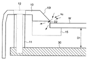
図1に示すように、本実施の形態の液処理装置は、被処理体である半導体ウエハW(以下、ウエハWと呼ぶ)の下面と側面に処理液を供給して、これらウエハWの下面と側面を洗浄して処理するものである。なお、本願で処理液とは、薬液や純水(リンス液)のことを意味している。そして、薬液としては、例えば、フッ酸、硝酸とフッ酸の混合溶液などを用いることができる。 As shown in FIG. 1, the liquid processing apparatus according to the present embodiment supplies a processing liquid to the lower surface and side surfaces of a semiconductor wafer W (hereinafter referred to as wafer W), which is an object to be processed. And the side is washed and processed. In the present application, the treatment liquid means a chemical solution or pure water (rinse solution). As the chemical solution, for example, hydrofluoric acid, a mixed solution of nitric acid and hydrofluoric acid, or the like can be used.
図1に示すように、液処理装置は、ウエハWの下面に処理液を供給する処理液供給機構37,39と、ウエハWを処理した処理液を排出する排出機構20,21と、ウエハWの周縁外方に設けられ、ウエハWを処理した処理液を排出機構20,21へと導く回転カップ10と、を備えている。
As shown in FIG. 1, the liquid processing apparatus includes processing
このうち、処理液供給機構37,39は、図1に示すように、処理液を供給する処理液供給部39と、処理液供給部39から供給された処理液をウエハWの下面側まで導く処理液供給管37とを有している。なお、処理液供給管37の上面は、処理液供給口37aを構成している。
Among these, the processing
また、排出機構20,21は、図1に示すように、回転カップ10によって導かれた処理液を受ける排液カップ20と、排液カップ20によって受けられた処理液を排出する排液管21と、を有している。また、排液カップ20の周りには、排気カップ26が設けられ、この排気カップ26には、排気カップ26内の窒素ガスなどの気体を吸引して排出する排気管25が設けられている。なお、この排気管25には、吸引力を付与する排出吸引部(図示せず)が連結されている。
As shown in FIG. 1, the
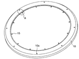
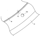
また、図1乃至図4に示すように、回転カップ10の下端には、周縁内方に突出し、ウエハWの周縁部の下面を支持する複数の支持ピン(支持部)15が設けられている。なお、図4は、図3のAの箇所を拡大した斜視図を示している。
As shown in FIGS. 1 to 4, a plurality of support pins (support portions) 15 that protrude inward at the periphery and support the lower surface of the periphery of the wafer W are provided at the lower end of the
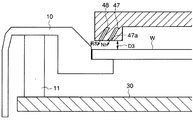
また、図1に示すように、支持ピン15によって支持されたウエハWの上面側には、このウエハWを覆うようにしてトッププレート40が設けられている。また、このトッププレート40内部には、窒素ガスやアルゴンガスなどの不活性ガス(本実施の形態では窒素ガス)を供給する不活性ガス供給部46に連結された不活性ガス供給管47が延在している。なお、不活性ガス供給管47は、トッププレート40の中心部で端部となっており、当該端部が不活性ガス供給口47aを構成している。また、図1に示すように、トッププレート40には、トッププレート40を上下方向に移動させるトッププレート駆動部49が連結されている。
Further, as shown in FIG. 1, a
また、図1に示すように、回転カップ10の下方側には、中空形状からなるベースプレート(ベース)30が設けられ、このベースプレート30には、下方に向かって延在する中空構造の回転軸31が設けられている。そして、回転軸31には、この回転軸31を回転させる回転駆動部60が連結されている。なお、このように回転軸31を回転させることによって、ベースプレート30および回転カップ10を回転させることができ、ひいては、回転カップ10に設けられた支持ピン15上のウエハWを回転させることができる。
As shown in FIG. 1, a hollow base plate (base) 30 is provided on the lower side of the
回転駆動部60は、図1に示すように、回転軸31の周縁外方に配置されたプーリ62と、このプーリ62に巻きかけられた駆動ベルト63と、この駆動ベルト63に駆動力を付与することによって、プーリ62を介して回転軸31を回転させるモータ61とを有している。また、回転軸31の周縁外方にはベアリング32が配置されている。
As shown in FIG. 1, the
また、図1に示すように、回転カップ10と回転軸31の中空内には、リフトピン35aを有し、中空形状からなるリフトピンプレート35と、このリフトピンプレート35から下方に延在し、中空形状からなるリフト軸36が配置されている。また、図1に示すように、リフトピンプレート35およびリフト軸36の内部(中空空間内)には、処理液供給管37が上下方向に延在している。なお、リフト軸36には、このリフト軸36を上下方向に移動させるリフト軸駆動部(図示せず)が連結されている。
Further, as shown in FIG. 1, a
また、図2に示すように、ベースプレート30と回転カップ10との間にはスペーサ11が配置されており、このスペーサ11内には、回転カップ10とベースプレート30とを締結するネジなどの締結部材12が設けられている。また、図3および図4に示すように、回転カップ10には締結部材12を貫通させるための孔部10aが設けられている。
Further, as shown in FIG. 2, a
なお、本実施の形態では、支持ピン15と回転カップ10とは一体成形され、一体に構成されている。また、スペーサ11と回転カップ10も一体成形され、一体に構成されている。
In the present embodiment, the
次に、このような構成からなる本実施の形態の作用について述べる。 Next, the operation of the present embodiment having such a configuration will be described.
まず、搬送ロボット(図示せず)によって、キャリア(図示せず)から取り出されたウエハWが、リフト軸駆動部(図示せず)により受け渡し位置(上方位置)に位置づけられたリフトピンプレート35のリフトピン35a上に載置される。このとき、トッププレート40は、トッププレート駆動部49によって、ウエハWの受け渡し位置よりも上方位置に位置づけられている。
First, a lift pin of a
次に、リフト軸駆動部(図示せず)によって、リフトピンプレート35が下方に移動させられてウエハ処理位置に位置づけられる(図1参照)。このようにリフトピンプレート35が下方に移動させられている間に、回転カップ10に設けられた支持ピン15によって、ウエハWの下面が支持される。その後、トッププレート駆動部49によって、トッププレート40が下方位置に位置づけられる。なお、本実施の形態では、回転カップ10の内周面10fが下方に向かって傾斜している(図2参照)。このため、例えウエハWが誤って回転カップ10上に配置された場合であっても、ウエハWを下方へ滑らせることができ、ウエハWを支持ピン15によって確実に支持させることができる。
Next, the
次に、回転駆動部60により回転軸31が回転駆動されることによって、ベースプレート30および回転カップ10が回転され、この結果、回転カップ10に設けられた支持ピン15上のウエハWが回転される(図1参照)。ここで、回転軸31は、モータ61から駆動ベルト63を介してプーリ62に駆動力が付与されることによって、回転駆動される。
Next, when the
このとき、ウエハWの下面には、処理液供給部39から供給された処理液が供給される(図1参照)。そして、ウエハWの下面に供給された処理液は、ウエハWが回転することによって発生する遠心力によって周縁外方に向かって移動される。
At this time, the processing liquid supplied from the processing
他方、トッププレート40の中心部に設けられた不活性ガス供給口47aからは窒素ガスが供給される(図1参照)。そして、この窒素ガスは、ウエハWの上面を経た後、ウエハWと回転カップ10との間の間隙D2に供給される(図2参照)。このため、ウエハWの周縁部に達した処理液が、毛細管現象によって、ウエハWと支持ピン15との間およびウエハWと回転カップ10との間から、ウエハWの上面側に回り込むことを防止することができる。
On the other hand, nitrogen gas is supplied from an inert
ところで、本実施の形態によれば、回転カップ10に、周縁内方に突出し、被処理体の周縁部の下面を支持する支持ピン15が設けられている。このため、回転カップ10をウエハWの周縁部に近接した位置に設けることができる(図2参照)。この結果、ウエハWの下面に供給された処理液が、ウエハWの周縁部から飛び散ることを防止することができる。
By the way, according to the present embodiment, the
また、支持ピン15によって支持されたウエハWの上面の位置を、回転カップ10の下面に対して均一にすることもできる(ウエハWの周縁部のあらゆる箇所で、ウエハWと回転カップ10との間の間隙D2を均一にすることができる)(図2参照)。このため、ウエハWの上面側を流れる窒素ガスの流れを均一にすることができるので、ウエハWの周縁部に達した処理液が、毛細管現象によって、ウエハWと支持ピン15および回転カップ10との間から、ウエハWの上面側に回り込むことをより確実に防止することができる。すなわち、本実施の形態によれば、ウエハWの周縁部のあらゆる箇所で、ウエハWと回転カップ10との間の間隙D2を均一にすることができるので、ウエハWと回転カップ10との間の間隙D2に供給される窒素ガスの量を均一にすることができる。このため、処理液がウエハWの上面側に回り込むことを防止するために必要な窒素ガスの量を容易に決めることができ、ウエハWの周縁部に達した処理液が、ウエハWの上面側に回り込むことをより確実に防止することができるのである。
In addition, the position of the upper surface of the wafer W supported by the support pins 15 can be made uniform with respect to the lower surface of the rotating cup 10 (the wafer W and the
また、このように、支持ピン15によって支持されたウエハWの上面の位置を回転カップ10の下面に対して均一にすることができるので、下方位置にあるトッププレート40の下端とウエハWの上面との間の間隙D3も、ウエハWの周縁部のあらゆる箇所で均一にすることができる(図5および図6参照)。このため、トッププレート40の下端を経てウエハWの周縁部に至る窒素ガスをより均一にすることができる。
Further, since the position of the upper surface of the wafer W supported by the support pins 15 can be made uniform with respect to the lower surface of the
なお、本実施の形態によれば、支持ピン15と回転カップ10とが一体で構成されているので、支持ピン15で支持されたウエハWと回転カップ10との間の間隙D2を確実に均一にすることができる。このため、ウエハWの上面側を流れる窒素ガスの流れをより均一にすることができ、ウエハWの周縁部に達した処理液がウエハWの上面側に回り込むことをさらに確実に防止することができる。
According to the present embodiment, since the support pins 15 and the
さらに、本実施の形態によれば、スペーサ11と回転カップ10とも一体で構成されている。このため、支持ピン15で支持されたウエハWの高さ位置を、ベースプレート30の高さ位置に対して均一にすることができる(ウエハWの周縁部のあらゆる箇所で、所定の距離D1を維持することができる)(図2参照)。この結果、ウエハWの下面側を流れる窒素ガスの流れを均一にすることができるので、ウエハWの処理精度をさらに向上させることができる。
Furthermore, according to the present embodiment, the
ところで、本実施の形態において、処理液供給機構37,39からウエハWの下面に供給される処理液を、適宜変更することができる。処理液供給機構37,39は、例えば、まず、希フッ酸(SC1)を供給し、その後、純水(DIW)を供給することができる。
In the present embodiment, the processing liquid supplied from the processing
上述のような処理液によるウエハWを洗浄する処理が終了すると、処理液供給部39からの処理液(例えば、純水)の供給が停止される。
When the process of cleaning the wafer W with the process liquid as described above is completed, the supply of the process liquid (for example, pure water) from the process
次に、回転駆動部60によって回転軸31が高速回転される。この結果、支持ピン15上のウエハWが高速回転され、ウエハWが乾燥される(図1参照)。その後、回転駆動機構60のモータ61が停止され、支持ピン15上のウエハWの回転も停止される(図1参照)。
Next, the
次に、トッププレート駆動部49によって、トッププレート40がウエハWの受け渡し位置よりも上方位置に位置づけられる。その後、リフト軸駆動部(図示せず)によって、リフトピンプレート35が上方位置に移動させられて、ウエハWが受け渡し位置(上方位置)に位置づけられる。
Next, the top
次に、搬送ロボット(図示せず)によって、リフトピンプレート35上からウエハWが除去される。このようにして、一枚のウエハWの処理が終了する。
Next, the wafer W is removed from the
ところで、上記では、トッププレート40の中心部に不活性ガス供給口47aが設けられている態様を用いて説明した。しかしながら、これに限ることなく、例えば、図5に示すように、トッププレート40の周縁部であってウエハWの周縁部に対向する位置に、不活性ガス供給管47が設けられていてもよい。
By the way, in the above, it demonstrated using the aspect in which the inert
また、ウエハWの上面側に、ウエハWと回転カップ10との間の間隙D2に、純水を供給する純水供給部48をさらに設けてもよい。具体的には、例えば図5に示すように、トッププレート40の周縁部であってウエハWの周縁部に対向する位置に、純水を供給する純水供給部48が設けられてもよい。このように純水供給部48を設けることによって、ウエハWの周縁部の上面もリンスすることができる。
Further, a pure
なお、上記では、支持ピン15と回転カップ10とが一体で構成されている態様を用いて説明した。しかしながら、これに限られることなく、支持ピン15が回転カップ10と別体を構成し、支持ピン15が回転カップ10に取り付けられるような構成からなっていてもよい。
In addition, in the above, it demonstrated using the aspect with which the
また、上記では、スペーサ11と回転カップ10とが一体で構成されている態様を用いて説明した。しかしながら、これに限られることなく、スペーサ11が回転カップ10と別体を構成し、スペーサ11が回転カップ10に取り付けられるような構成からなっていてもよい。
Moreover, in the above, it demonstrated using the aspect with which the
第2の実施の形態
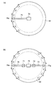
次に、図6および図7(a)(b)により、本発明の第2の実施の形態について説明する。図6および図7(a)(b)に示す第2の実施の形態は、トッププレート40が回転カップ10の上方まで延びた周縁外方突出部40pを有している。また、周縁外方突出部40p内には、吸引力を付与する吸引部70に連結された吸引管75が延在しており、吸引管75の吸引部70と反対側の端部が、周縁外方突出部40pに付着した処理液を吸引する吸引口75aを構成している。なお、これら吸引部70と吸引管75によって、吸引機構が構成されている。その他の構成は、図1乃至図5に示す第1の実施の形態と略同一である。
Second Embodiment Next, a second embodiment of the present invention will be described with reference to FIGS. 6 and 7A and 7B. In the second embodiment shown in FIG. 6 and FIGS. 7A and 7B, the
図6および図7(a)(b)に示す第2の実施の形態において、図1乃至図5に示す第1の実施の形態と同一部分には同一符号を付して詳細な説明は省略する。 In the second embodiment shown in FIG. 6 and FIGS. 7A and 7B, the same parts as those in the first embodiment shown in FIGS. To do.
図6に示すように、周縁外方突出部40pに、吸引部70に連結された吸引管75の吸引口75aが設けられている。そして、図7(a)に示すように、トッププレート40の周縁外方突出部40pの下面や下方外側面40q(図6参照)に付着した純水(処理液供給機構37,39から供給された純水)には、回転カップ10が回転することによって生じる気流の流れによって、回転力が付与される。このため、周縁外方突出部40pの下面や下方外側面40qに付着した処理液は、これら周縁外方突出部40pの下面や下方外側面40q上を移動し、吸引口75aから吸引されることとなる。
As shown in FIG. 6, the
なお、周縁外方突出部40pの周縁外方側(トッププレート40の半径方向において吸引口75aから離れた位置)に付着した処理液は、周縁外方突出部40pと回転カップ10との間に発生する気流の流れによって、周縁外方突出部40pの周縁外方に向かって流れて除去されることとなる(図6および図7(a)参照)。また、回転カップ10の上面に付着した処理液は、回転カップ10が回転することによって発生する遠心力によって、周縁外方突出部40pと回転カップ10との間から周縁外方に向かって流れて除去されることとなる。
The treatment liquid adhering to the outer peripheral edge of the peripheral outer protrusion 40p (position away from the
これらのことから、処理液が、回転カップ10の内周端とウエハWの外周端との間からウエハWの上方へと飛び散って、周縁外方突出部40pの下面、下方外側面40qおよび回転カップ10の上面に付着した場合であっても(図6参照)、当該処理液を確実に除去することができる。
For these reasons, the processing liquid scatters from between the inner peripheral end of the
従って、搬送ロボット(図示せず)によって、処理済みのウエハWがトッププレート40の下方を移動されるときに、トッププレート40の周縁外方突出部40pの下面や下方外側面40qに付着した処理液が、当該ウエハW上に落ちることを防止することができる。また、周縁外方突出部40pの下面や下方外側面40qに付着した処理液によって、次回以降に処理されるウエハWに、悪影響を及ぼされることも防止することができる。
Accordingly, when the processed wafer W is moved below the
さらに、周縁外方突出部40pの下面や下方外側面40q上を移動する処理液によって、これら周縁外方突出部40pの下面や下方外側面40qを洗浄することができる。このため、周縁外方突出部40pの下面および下方外側面40qを、清潔な状態で維持することができる。 Further, the lower surface and the lower outer surface 40q of the outer peripheral protrusion 40p can be cleaned by the processing liquid that moves on the lower surface and the lower outer surface 40q of the outer peripheral protrusion 40p. For this reason, the lower surface and the lower outer surface 40q of the peripheral outer protrusion 40p can be maintained in a clean state.
なお、上記では、周縁外方突出部40pに1個の吸引口75aが設けられている態様を用いて説明した。しかしながら、これに限られることなく、図7(b)に示すように、周縁外方突出部40pに2個の吸引口(第一吸引口76aおよび第二吸引口77a)が設けられてもよい。
In addition, in the above, it demonstrated using the aspect in which the one
この場合には、吸引部70と反対側の端部が第一吸引口76aを構成する第一吸引管76に、開閉自在の第一バルブ71が設けられ、吸引部70と反対側の端部が第二吸引口77aを構成する第二吸引管77に、開閉自在の第二バルブ72が設けられている。
In this case, a
このため、第一バルブ71および第二バルブ72の開閉状態を調整することによって、第一吸引口76aと第二吸引口77aで吸引される処理液の種類を代えることができる。例えば、第一吸引口76aを再利用する処理液を吸引するために利用し、第二吸引口77aは、排液として処理する処理液を吸引するために利用することができる。また、第一吸引口76aを薬液を吸引するために利用し、第二吸引口77aを純水を吸引するために利用することもできる。
For this reason, by adjusting the open / close state of the
なお、第一吸引口76aによって処理液を吸引する場合には、第一バルブ71が開状態となり第二バルブ72が閉状態となっている。他方、第二吸引口77aによって処理液を吸引する場合には、第一バルブ71が閉状態となり第二バルブ72が開状態となっている。
When the processing liquid is sucked through the
ところで、上述した各実施の形態において、ウエハWの下面の中心部に処理液が供給され、ウエハWの下面全体と側面が処理される態様を用いて説明したが、これに限られることなく、ウエハWの下面の周縁部に処理液が供給され、ウエハWの下面の周縁部と側面が処理されるものであってもよい。 By the way, in each of the above-described embodiments, the processing liquid is supplied to the central portion of the lower surface of the wafer W and the entire lower surface and side surfaces of the wafer W are processed. However, the present invention is not limited to this. The processing liquid may be supplied to the peripheral portion of the lower surface of the wafer W, and the peripheral portion and the side surface of the lower surface of the wafer W may be processed.
W ウエハ(被処理体)
10 回転カップ
11 スペーサ
15 支持ピン(支持部)
20 排液カップ
21 排液管
25 排気管
26 排気カップ
30 ベースプレート(ベース)
37 処理液供給管
39 処理液供給部
40 トッププレート
40p 周縁外方突出部
47 不活性ガス供給管
48 純水供給部
60 回転駆動部
70 吸引部
71 第一バルブ
72 第二バルブ
75,76,77 吸引管
W wafer (object to be processed)
10 Rotating
20
37 treatment
Claims (9)
前記被処理体に処理液を供給する処理液供給機構と、
前記被処理体を処理した処理液を排出する排出機構と、
前記被処理体の周縁外方に設けられ、前記被処理体を処理した処理液を前記排出機構へと導く回転カップと、
前記回転カップに設けられ、周縁内方に突出し、前記被処理体の周縁部を支持する支持部と、
前記回転カップを回転させる回転駆動部と、
を備えたことを特徴とする液処理装置。 In the liquid processing apparatus for processing the lower surface and the side surface of the object to be processed,
A processing liquid supply mechanism for supplying a processing liquid to the object to be processed;
A discharge mechanism for discharging the processing liquid that has processed the object to be processed;
A rotating cup that is provided outside the periphery of the object to be processed and guides the processing liquid that has processed the object to be processed to the discharge mechanism;
A support portion that is provided on the rotating cup, protrudes inwardly at the periphery, and supports the periphery of the object to be processed;
A rotation driving unit for rotating the rotating cup;
A liquid processing apparatus comprising:
前記トッププレートは、前記回転カップの上方まで延びた周縁外方突出部を有し、
前記周縁外方突出部に、該周縁外方突出部に付着した処理液を吸引する吸引口を有する吸引機構が設けられていることを特徴とする請求項1乃至3のいずれか1項に記載の液処理装置。 A top plate provided on the upper surface side of the object to be processed and covering the object to be processed;
The top plate has a peripheral outward protrusion that extends to above the rotating cup;
4. The suction mechanism according to claim 1, wherein a suction mechanism having a suction port for sucking the processing liquid adhering to the peripheral outer protrusion is provided in the peripheral outer protrusion. 5. Liquid processing equipment.
前記第二吸引口は、排液として処理する処理液を吸引することを特徴とする請求項5に記載の液処理装置。 The first suction port sucks a processing liquid to be reused,
The liquid processing apparatus according to claim 5, wherein the second suction port sucks a processing liquid to be processed as waste liquid.
前記第一吸引口は、洗浄液を吸引し、
前記第二吸引口は、リンス液を吸引することを特徴とする請求項5に記載の液処理装置。 The processing liquid supplied from the processing liquid supply mechanism to the object to be processed includes a cleaning liquid and a rinsing liquid,
The first suction port sucks cleaning liquid,
The liquid processing apparatus according to claim 5, wherein the second suction port sucks a rinse liquid.
前記ベースと前記回転カップとの間に配置されたスペーサと、をさらに備え、
前記スペーサと前記回転カップとが一体で構成されることを特徴とする請求項1乃至8のいずれか1項に記載の液処理装置。 A base provided on a lower side of the rotary cup and rotated by the rotary drive unit;
A spacer disposed between the base and the rotating cup,
The liquid processing apparatus according to claim 1, wherein the spacer and the rotating cup are integrally formed.
Priority Applications (4)
| Application Number | Priority Date | Filing Date | Title |
|---|---|---|---|
| JP2008191344A JP5355951B2 (en) | 2008-07-24 | 2008-07-24 | Liquid processing equipment |
| KR1020090064964A KR101377196B1 (en) | 2008-07-24 | 2009-07-16 | Liquid treatment apparatus |
| US12/506,506 US8590547B2 (en) | 2008-07-24 | 2009-07-21 | Liquid processing apparatus |
| TW098125031A TWI446418B (en) | 2008-07-24 | 2009-07-24 | Liquid processing device |
Applications Claiming Priority (1)
| Application Number | Priority Date | Filing Date | Title |
|---|---|---|---|
| JP2008191344A JP5355951B2 (en) | 2008-07-24 | 2008-07-24 | Liquid processing equipment |
Publications (2)
| Publication Number | Publication Date |
|---|---|
| JP2010028059A true JP2010028059A (en) | 2010-02-04 |
| JP5355951B2 JP5355951B2 (en) | 2013-11-27 |
Family
ID=41567547
Family Applications (1)
| Application Number | Title | Priority Date | Filing Date |
|---|---|---|---|
| JP2008191344A Active JP5355951B2 (en) | 2008-07-24 | 2008-07-24 | Liquid processing equipment |
Country Status (4)
| Country | Link |
|---|---|
| US (1) | US8590547B2 (en) |
| JP (1) | JP5355951B2 (en) |
| KR (1) | KR101377196B1 (en) |
| TW (1) | TWI446418B (en) |
Cited By (4)
| Publication number | Priority date | Publication date | Assignee | Title |
|---|---|---|---|---|
| JP2011222965A (en) * | 2010-03-24 | 2011-11-04 | Tokyo Electron Ltd | Liquid processing apparatus, liquid processing method, and recording medium with program recorded therein to implement liquid processing method |
| KR20120028212A (en) | 2010-09-13 | 2012-03-22 | 도쿄엘렉트론가부시키가이샤 | Liquid processing apparatus, liquid processing method and storage medium |
| JP2012084607A (en) * | 2010-10-07 | 2012-04-26 | Tokyo Electron Ltd | Liquid processing apparatus |
| US9305767B2 (en) | 2011-03-16 | 2016-04-05 | Tokyo Electron Limited | Liquid processing apparatus, liquid processing method and storage medium |
Families Citing this family (3)
| Publication number | Priority date | Publication date | Assignee | Title |
|---|---|---|---|---|
| JP5457381B2 (en) * | 2010-02-22 | 2014-04-02 | 東京エレクトロン株式会社 | Development processing apparatus and development processing method |
| JP5951444B2 (en) * | 2012-10-25 | 2016-07-13 | 東京エレクトロン株式会社 | Substrate processing apparatus and substrate processing method |
| JP6017262B2 (en) * | 2012-10-25 | 2016-10-26 | 東京エレクトロン株式会社 | Substrate processing apparatus and substrate processing method |
Citations (4)
| Publication number | Priority date | Publication date | Assignee | Title |
|---|---|---|---|---|
| JP2000077378A (en) * | 1998-08-27 | 2000-03-14 | Dainippon Screen Mfg Co Ltd | Substrate processor |
| JP2003286597A (en) * | 2002-03-27 | 2003-10-10 | Dainippon Screen Mfg Co Ltd | Substrate-treating apparatus and plating apparatus equipped with the same |
| JP2004265912A (en) * | 2003-02-03 | 2004-09-24 | Personal Creation Ltd | Processing system of substrate |
| JP2008117971A (en) * | 2006-11-06 | 2008-05-22 | Tokyo Electron Ltd | Liquid processing apparatus |
Family Cites Families (8)
| Publication number | Priority date | Publication date | Assignee | Title |
|---|---|---|---|---|
| JP3102831B2 (en) | 1994-06-20 | 2000-10-23 | 大日本スクリーン製造株式会社 | Rotary processing equipment |
| TW442336B (en) * | 1997-08-19 | 2001-06-23 | Tokyo Electron Ltd | Film forming method |
| TW459266B (en) * | 1997-08-27 | 2001-10-11 | Tokyo Electron Ltd | Substrate processing method |
| JP3745214B2 (en) | 2000-09-27 | 2006-02-15 | 大日本スクリーン製造株式会社 | Bevel etching apparatus and bevel etching method |
| JP3892792B2 (en) * | 2001-11-02 | 2007-03-14 | 大日本スクリーン製造株式会社 | Substrate processing apparatus and substrate cleaning apparatus |
| US7584760B2 (en) * | 2002-09-13 | 2009-09-08 | Dainippon Screen Mfg. Co., Ltd. | Substrate processing apparatus |
| JP4409312B2 (en) | 2004-02-18 | 2010-02-03 | 大日本スクリーン製造株式会社 | Substrate peripheral processing apparatus and substrate peripheral processing method |
| DE602007000584D1 (en) * | 2006-06-16 | 2009-04-09 | Tokio Electron Ltd | Liquid processing apparatus and method |
-
2008
- 2008-07-24 JP JP2008191344A patent/JP5355951B2/en active Active
-
2009
- 2009-07-16 KR KR1020090064964A patent/KR101377196B1/en active IP Right Grant
- 2009-07-21 US US12/506,506 patent/US8590547B2/en active Active
- 2009-07-24 TW TW098125031A patent/TWI446418B/en active
Patent Citations (4)
| Publication number | Priority date | Publication date | Assignee | Title |
|---|---|---|---|---|
| JP2000077378A (en) * | 1998-08-27 | 2000-03-14 | Dainippon Screen Mfg Co Ltd | Substrate processor |
| JP2003286597A (en) * | 2002-03-27 | 2003-10-10 | Dainippon Screen Mfg Co Ltd | Substrate-treating apparatus and plating apparatus equipped with the same |
| JP2004265912A (en) * | 2003-02-03 | 2004-09-24 | Personal Creation Ltd | Processing system of substrate |
| JP2008117971A (en) * | 2006-11-06 | 2008-05-22 | Tokyo Electron Ltd | Liquid processing apparatus |
Cited By (11)
| Publication number | Priority date | Publication date | Assignee | Title |
|---|---|---|---|---|
| JP2011222965A (en) * | 2010-03-24 | 2011-11-04 | Tokyo Electron Ltd | Liquid processing apparatus, liquid processing method, and recording medium with program recorded therein to implement liquid processing method |
| KR20120028212A (en) | 2010-09-13 | 2012-03-22 | 도쿄엘렉트론가부시키가이샤 | Liquid processing apparatus, liquid processing method and storage medium |
| JP2012084856A (en) * | 2010-09-13 | 2012-04-26 | Tokyo Electron Ltd | Liquid processing apparatus, liquid processing method, and storage medium |
| US8887741B2 (en) | 2010-09-13 | 2014-11-18 | Tokyo Electron Limited | Liquid processing apparatus, liquid processing method and storage medium |
| TWI483333B (en) * | 2010-09-13 | 2015-05-01 | Tokyo Electron Ltd | Liquid processing apparatus, liquid processing method, and recording medium |
| KR101590661B1 (en) | 2010-09-13 | 2016-02-01 | 도쿄엘렉트론가부시키가이샤 | Liquid processing apparatus, liquid processing method and storage medium |
| JP2012084607A (en) * | 2010-10-07 | 2012-04-26 | Tokyo Electron Ltd | Liquid processing apparatus |
| US8741099B2 (en) | 2010-10-07 | 2014-06-03 | Tokyo Electron Limited | Liquid processing apparatus |
| KR101507487B1 (en) | 2010-10-07 | 2015-04-06 | 도쿄엘렉트론가부시키가이샤 | Liquid processing apparatus |
| TWI500076B (en) * | 2010-10-07 | 2015-09-11 | Tokyo Electron Ltd | Liquid treatment apparatus |
| US9305767B2 (en) | 2011-03-16 | 2016-04-05 | Tokyo Electron Limited | Liquid processing apparatus, liquid processing method and storage medium |
Also Published As
| Publication number | Publication date |
|---|---|
| TW201013762A (en) | 2010-04-01 |
| JP5355951B2 (en) | 2013-11-27 |
| US8590547B2 (en) | 2013-11-26 |
| KR20100011909A (en) | 2010-02-03 |
| TWI446418B (en) | 2014-07-21 |
| KR101377196B1 (en) | 2014-03-25 |
| US20100018557A1 (en) | 2010-01-28 |
Similar Documents
| Publication | Publication Date | Title |
|---|---|---|
| JP5355951B2 (en) | Liquid processing equipment | |
| JP6229933B2 (en) | Processing cup cleaning method, substrate processing method, and substrate processing apparatus | |
| JP4018958B2 (en) | Substrate processing equipment | |
| KR101280768B1 (en) | Substrate treatment apparatus and substrate treatment method | |
| JP4723001B2 (en) | Substrate processing apparatus, substrate processing method, and drainage cup cleaning method | |
| TWI538044B (en) | Cleaning jig and cleaning method for cleaning substrate processing device, and substrate processing system | |
| JP4825178B2 (en) | Substrate processing equipment | |
| KR101932775B1 (en) | Liquid processing apparatus, jig for cleaning and cleaning method | |
| JP4990174B2 (en) | Substrate processing equipment | |
| JP5031671B2 (en) | Liquid processing apparatus, liquid processing method, and storage medium | |
| JPWO2008013118A1 (en) | Liquid processing apparatus and liquid processing method | |
| JP2009135396A (en) | Substrate treating apparatus and method for processing substrate | |
| JP5143657B2 (en) | Liquid processing equipment | |
| JP2009194167A (en) | Liquid processing apparatus | |
| JP4457046B2 (en) | Substrate processing equipment | |
| TW201250887A (en) | Substrate liquid processing apparatus | |
| JP4805051B2 (en) | Liquid processing equipment | |
| JP6159200B2 (en) | Substrate processing apparatus and cleaning jig | |
| JP2007005711A (en) | Substrate processing apparatus and substrate processing method | |
| KR100745482B1 (en) | Apparatus for treating backside of substrate | |
| JP2019106560A (en) | Substrate processing device and substrate processing method | |
| KR102648039B1 (en) | Substrate processing method and substrate processing device | |
| JP6513774B2 (en) | Substrate processing apparatus and substrate processing method | |
| JP2003045772A (en) | Spin treatment apparatus | |
| JP2010267690A (en) | Substrate processing apparatus and substrate processing method |
Legal Events
| Date | Code | Title | Description |
|---|---|---|---|
| A621 | Written request for application examination |
Free format text: JAPANESE INTERMEDIATE CODE: A621 Effective date: 20100823 |
|
| A977 | Report on retrieval |
Free format text: JAPANESE INTERMEDIATE CODE: A971007 Effective date: 20120116 |
|
| A131 | Notification of reasons for refusal |
Free format text: JAPANESE INTERMEDIATE CODE: A131 Effective date: 20120302 |
|
| A521 | Request for written amendment filed |
Free format text: JAPANESE INTERMEDIATE CODE: A523 Effective date: 20120425 |
|
| A131 | Notification of reasons for refusal |
Free format text: JAPANESE INTERMEDIATE CODE: A131 Effective date: 20121030 |
|
| A521 | Request for written amendment filed |
Free format text: JAPANESE INTERMEDIATE CODE: A523 Effective date: 20121213 |
|
| A131 | Notification of reasons for refusal |
Free format text: JAPANESE INTERMEDIATE CODE: A131 Effective date: 20130507 |
|
| A521 | Request for written amendment filed |
Free format text: JAPANESE INTERMEDIATE CODE: A523 Effective date: 20130624 |
|
| TRDD | Decision of grant or rejection written | ||
| A01 | Written decision to grant a patent or to grant a registration (utility model) |
Free format text: JAPANESE INTERMEDIATE CODE: A01 Effective date: 20130802 |
|
| A61 | First payment of annual fees (during grant procedure) |
Free format text: JAPANESE INTERMEDIATE CODE: A61 Effective date: 20130828 |
|
| R150 | Certificate of patent or registration of utility model |
Ref document number: 5355951 Country of ref document: JP Free format text: JAPANESE INTERMEDIATE CODE: R150 Free format text: JAPANESE INTERMEDIATE CODE: R150 |
|
| R250 | Receipt of annual fees |
Free format text: JAPANESE INTERMEDIATE CODE: R250 |
|
| R250 | Receipt of annual fees |
Free format text: JAPANESE INTERMEDIATE CODE: R250 |
|
| R250 | Receipt of annual fees |
Free format text: JAPANESE INTERMEDIATE CODE: R250 |
|
| R250 | Receipt of annual fees |
Free format text: JAPANESE INTERMEDIATE CODE: R250 |
|
| R250 | Receipt of annual fees |
Free format text: JAPANESE INTERMEDIATE CODE: R250 |
|
| R250 | Receipt of annual fees |
Free format text: JAPANESE INTERMEDIATE CODE: R250 |