JP2010022880A - Game machine - Google Patents

Game machine Download PDF

Info

Publication number
JP2010022880A
JP2010022880A JP2009255131A JP2009255131A JP2010022880A JP 2010022880 A JP2010022880 A JP 2010022880A JP 2009255131 A JP2009255131 A JP 2009255131A JP 2009255131 A JP2009255131 A JP 2009255131A JP 2010022880 A JP2010022880 A JP 2010022880A
Authority
JP
Japan
Prior art keywords
image
game
display
symbol
special
Prior art date
Legal status (The legal status is an assumption and is not a legal conclusion. Google has not performed a legal analysis and makes no representation as to the accuracy of the status listed.)
Granted
Application number
JP2009255131A
Other languages
Japanese (ja)
Other versions
JP4973717B2 (en
Inventor
Masahiro Takeuchi
正博 竹内
Yoshio Wakana
芳生 若菜
Makoto Tayui
誠 田結
Hidekatsu Takeuchi
英勝 竹内
Seiichi Yanagawa
誠市 梁川
Current Assignee (The listed assignees may be inaccurate. Google has not performed a legal analysis and makes no representation or warranty as to the accuracy of the list.)
Takeya Co Ltd
Original Assignee
Takeya Co Ltd
Priority date (The priority date is an assumption and is not a legal conclusion. Google has not performed a legal analysis and makes no representation as to the accuracy of the date listed.)
Filing date
Publication date
Application filed by Takeya Co Ltd filed Critical Takeya Co Ltd
Priority to JP2009255131A priority Critical patent/JP4973717B2/en
Publication of JP2010022880A publication Critical patent/JP2010022880A/en
Application granted granted Critical
Publication of JP4973717B2 publication Critical patent/JP4973717B2/en
Anticipated expiration legal-status Critical
Expired - Fee Related legal-status Critical Current

Links

Images

Abstract

<P>PROBLEM TO BE SOLVED: To provide a game machine capable of increasing the performance effect of a display image such as a big winning performance image to be displayed at an image display device and improving the amusement of a game. <P>SOLUTION: When a big winning symbol is established and displayed at a special symbol display device 6, a big winning game is generated, and a big winning game start specifying command q signal is input from a main control circuit to a display control circuit, big winning performance images are displayed until completed for prescribed time (TB+TR+TN) regardless of the time (TB+TR) of the big winning game of a player at the image display device 80 provided at a game board separately from the special symbol display device 6. In the meantime, at the special symbol display device 6, information about the big winning is displayed during the time (TB+TR) of the big winning game on the basis of prescribed commands for display control (r, s, u). <P>COPYRIGHT: (C)2010,JPO&INPIT

Description

本発明は、パチンコ機やスロットマシーン等の遊技機に係わり、特に画像表示装置に所定の図柄を変動表示させると共に所定の演出画像の表示を行う表示制御機能を有する遊技機に関する。   The present invention relates to a gaming machine such as a pachinko machine or a slot machine, and more particularly to a gaming machine having a display control function for displaying a predetermined effect image and displaying a predetermined effect image on an image display device.

従来より、遊技機は、その趣向性の向上のために様々な工夫がなされている。中でも遊技領域上に画像表示装置を備えた遊技機は、画像表示装置の表示方法の工夫如何で、遊技機の人気、不人気が決まるので特に様々な工夫が施されている。代表的な画像表示装置を備えた遊技機としては、例えば通称フィーバー型パチンコ遊技機があり、このタイプの遊技は、液晶表示装置等の画像表示装置としての特別図柄表示装置の画像表示部に特別図柄を表示する3つの図柄表示部が設定され、始動入賞口の入賞に基づいて各図柄表示部に特別図柄としての絵柄、キャラクタ、数字、記号、文字等が回転する様子等を示す擬似的な画像としての変動表示を表示し、所定時間経過後に変動表示を停止させ、停止した特別図柄の図柄合わせを行うものである。   Conventionally, game machines have been devised in various ways to improve their preferences. In particular, a gaming machine equipped with an image display device on a gaming area has various contrivances because the popularity and unpopularity of the gaming machine is determined depending on the display method of the image display device. As a game machine equipped with a typical image display device, for example, there is a so-called fever-type pachinko game machine. Three symbol display parts for displaying symbols are set, and a pseudo pattern showing a state where a picture, a character, a number, a symbol, a character, etc. as a special symbol is rotated on each symbol display part on the basis of a winning of a start winning opening. A variable display as an image is displayed, the variable display is stopped after a lapse of a predetermined time, and the stopped special symbols are matched.

上記変動表示の結果、各図柄表示部の停止図柄が予め定められた所定の図柄の組合せ(大当り図柄)であると、遊技状態を遊技者に極めて価値のある特別遊技(大当り遊技)へ移行されるようになっており、この特別遊技の間には、褒賞として画像表示部に大当り演出画像が表示されるようになっている。   As a result of the above variable display, if the stop symbol of each symbol display unit is a predetermined symbol combination (big hit symbol) determined in advance, the gaming state is shifted to a special game (big hit game) that is extremely valuable to the player. During this special game, a big hit effect image is displayed on the image display unit as a reward.

なお、この特別遊技は、一般的に複数のラウンド(例えば第1ラウンド〜第16ラウンド)と、このラウンド間に設けられるインターバル等とによって構成されており、各ラウンド時間は、アタッカと呼ばれる大入賞口等、遊技者にとって有利な状態に変換された所定の入賞口に所定数(例えば10個)の遊技球が入賞するまでとなっている。従って、この特別遊技におけるラウンド時間は一定になることはなく、各ラウンド毎にまちまちとなる。さらに、この大入賞口には特定領域が設けられており、大入賞口に入賞した遊技球がこの特定領域を通過しないと次のラウンドには進めないようになっており、つまり特別遊技は、大入賞口に入賞した遊技球がこの特定領域を通過しないと、そのラウンドで終了するようになっている。従って、特別遊技が実行される時間は、これらの理由により、遊技者によってまちまちとなり不特定な時間となる。   This special game is generally composed of a plurality of rounds (for example, the first round to the 16th round) and intervals provided between the rounds, and each round time is a big prize called an attacker. Until a predetermined number (for example, 10) of game balls wins a predetermined winning opening converted into a state advantageous to the player such as a mouth. Therefore, the round time in this special game is not constant, and varies for each round. Furthermore, this special winning opening has a specific area, and the game balls that won the special winning opening do not pass through this specific area so that they cannot advance to the next round. If the game ball that has won the big prize opening does not pass through this specific area, the round ends. Accordingly, the time for which the special game is executed varies depending on the player for these reasons, and becomes an unspecified time.

ところで、パチンコ遊技機では遊技者に対するさらなるサービスの向上が常に求められており、従い近年においては、より遊技の興趣が増すように、この大当り演出画像に連続性や物語性をもたせて演出効果を高かめるもの(以下、従来技術という)が提案されている。   By the way, pachinko machines are constantly demanding further improvements in services to players, and in recent years, therefore, this jackpot effect image has a continuity and narrative so that it can be more interesting. Something that has been raised (hereinafter referred to as conventional technology) has been proposed.

しかし、この従来技術における大当り演出画像では、上記したようにラウンド時間が一定ではないことから、各ラウンド毎に独立して物語の進行が行われるのみで、特別遊技の全般にわたって物語の進行が行われることはなく、従って短く簡単な内容の物語しか表示できないという問題点があり、さらに、この各ラウンド毎による物語の進行も、ラウンド時間が一定ではないという理由から、大入賞口に遊技球が所定個数入賞しなかった時のラウンドの最長時間に合わせて表示されるので、殆どの遊技者は、物語が完結する場面を見ることができないという問題点もある。   However, in this big hit effect image in the prior art, since the round time is not constant as described above, only the story progresses independently for each round, and the story progresses over the entire special game. Therefore, there is a problem that only a short and simple story can be displayed, and further, the progress of the story for each round is not constant, so the game ball is placed at the big prize opening. Since it is displayed according to the longest time of the round when the predetermined number is not won, most players have a problem that the scene where the story is completed cannot be seen.

また、この従来技術では、インターバル中においては物語の進行画面は表示されず、例えば特別遊技を獲得したときの大当り図柄や次に実行されるラウンド数の表示がなされる
ようになっており、さらに、ラウンド中の特別遊技に係わる情報として、例えば大入賞口に入賞した遊技球のカウント表示や遊技球が特定領域を通過したことを報知するV(ラウンド継続)表示等が、大当り演出画像に重なるように表示されるので、つまり大当り演出画像はすぐに途絶えるようになっているので、従ってこの大当り演出画像を見ている遊技者は、すぐに興醒めしてしまうという問題点もある。
Also, in this prior art, the progress screen of the story is not displayed during the interval, and for example, the jackpot symbol when the special game is acquired and the number of rounds to be executed next are displayed. As information related to the special game during the round, for example, a count display of the game balls won in the big prize opening, a V (round continuation) display for notifying that the game balls have passed the specific area, and the like overlap with the big hit effect image. In other words, the jackpot effect image is immediately interrupted, so that the player who is viewing the jackpot effect image is immediately awakened.

そこで、各ラウンドごとに割り当てられて進行型演出動画(大当り動画)の一部を構成する進行型部分動画を、ラウンドの時間に適合する長さに調整し得る時間調整手段を介して完結的に表示可能とした大当り演出画像が開示されており(例えば、特許文献1参照)、この大当り演出画像においては、インターバル中に表示する画像は、各進行型部分動画の到達度を示す到達画像を表示するようになっている(以下、従来技術1という)。   Therefore, the progressive partial video, which is assigned to each round and forms a part of the progressive production video (big hit video), is completed through time adjustment means that can adjust the length to match the round time. A jackpot effect image that can be displayed is disclosed (see, for example, Patent Document 1). In this jackpot effect image, an image displayed during the interval displays a reaching image that indicates the degree of attainment of each progressive partial moving image. (Hereinafter referred to as prior art 1).

特開2001−346967号公報JP 2001-346967 A

しかし、この従来技術1においては、進行型部分動画は、車両の進行や人の走行等の単純進行型動画に制約され、これにより特別遊技の全般にわたって、インターバル中であるか否かにかかわらず物語の進行が行われるようにしたり、また、物語が途中で終了しても違和感のないようにしたり、またさらに、時間調整手段を、大入賞口への入賞消化速度により変化させるようにして、物語を完結的に表示するようにしている。   However, in this prior art 1, the progressive partial moving image is restricted to a simple progressive moving image such as the progress of a vehicle or the running of a person, and thus, regardless of whether it is during an interval throughout the special game. Make sure that the story progresses, make sure that there is no sense of incompatibility even if the story ends in the middle, and further, change the time adjustment means according to the rate of winning the winning prize, The story is displayed completely.

従って、このような単純進行型動画に制約される従来技術1の大当り演出画像では、遊技の趣向を向上させることは困難であり、遊技者の遊技意欲を高めることはできない。また、インターバル中に表示する画像を到達画像とした場合には、各進行型部分動画との調和をはかることはできるものの、全体的にみると、大当り動画の連続性や物語性の低下は免れることはできないという問題点もある。さらにまた、上記したようなカウント表示やV(ラウンド継続)表示等のラウンド中の特別遊技に係わる情報は、依然として大当り演出画像に重なるように表示されるので、つまり大当り演出画像はすぐに途絶えてしまうので、従ってこの大当り演出画像を見ている遊技者は、すぐに興醒めしてしまうという問題点は改善されていない。   Therefore, in the big hit effect image of the prior art 1 restricted by such a simple progressive video, it is difficult to improve the game taste, and the player's willingness to play cannot be increased. In addition, when the image to be displayed during the interval is a reaching image, it can be harmonized with each of the progressive partial videos, but overall, the continuity of the big hit video and the deterioration of the narrative are avoided. There is also the problem that it cannot be done. Furthermore, information related to special games during the round, such as the count display and the V (continuous round) display as described above, is still displayed so as to overlap the jackpot effect image, that is, the jackpot effect image is immediately interrupted. Therefore, the problem that the player who is viewing the jackpot effect image is immediately awakened is not improved.

本発明は、上記した問題点を解決するためになされたもので、その目的とするところは、画像表示装置に表示する大当り演出画像等のような表示画像の演出効果を高め、遊技の趣向を向上することのできる遊技機を提供することにある。   The present invention has been made to solve the above-described problems, and the object of the present invention is to enhance the effect of the display image such as the jackpot effect image displayed on the image display device, and to enhance the game taste. An object is to provide a gaming machine that can be improved.

このような問題を解決するために、本発明の遊技機は、請求項1に記載したように、遊技球が入賞または通過可能な遊技装置と、該遊技装置に入賞または通過した遊技球を検出する遊技球検出手段と、該遊技球検出手段が遊技球を検出したことに基づいて、所定の表示制御用コマンド信号を送信する主制御手段と、該主制御手段から送信された所定の表示制御用コマンド信号を受信することにより、少なくとも所定の図柄を画像表示装置に変動表示して確定表示する表示制御を行う表示制御手段と、を備えた遊技機であって、上記主制御手段は、上記遊技球検出手段が遊技球を検出したことに基づいて、遊技者にとって有利な特別遊技を発生させるか否かを判定する特別遊技判定手段を備え、上記表示制御手段は、該特別遊技判定手段が特別遊技を発生させると判定した場合には、上記画像表示装置に所定の大当り図柄を確定表示した後に所定の特別演出画像を表示する特別演出画像表示手段を備え、該特別演出画像表示手段により表示される上記所定の特別演出画像は、上記特別遊技の実行には関係なく、予め設定されている時間継続して上記画像表示装置に表示されることを特徴とする。   In order to solve such problems, the gaming machine of the present invention detects a gaming device in which a gaming ball can win or pass, and a gaming ball that has won or passed through the gaming device, as described in claim 1. A game ball detecting means for detecting a game ball detected by the game ball detecting means, a main control means for transmitting a predetermined display control command signal, and a predetermined display control sent from the main control means. Display control means for performing display control for receiving and displaying at least a predetermined symbol on an image display device and confirming display by receiving a command signal for use, wherein the main control means includes: Special game determination means for determining whether or not to generate a special game advantageous to the player based on the detection of the game ball by the game ball detection means; and the display control means includes the special game determination means. special When it is determined that the technique is to be generated, the image display device includes a special effect image display means for displaying a predetermined special effect image after a predetermined display of a predetermined jackpot symbol is confirmed and displayed by the special effect image display means. The predetermined special effect image is displayed on the image display device continuously for a preset time regardless of the execution of the special game.

また、請求項2に記載の遊技機は、遊技球が入賞または通過可能な遊技装置と、該遊技装置に入賞または通過した遊技球を検出する遊技球検出手段と、該遊技球検出手段が遊技球を検出したことに基づいて、所定の表示制御用コマンド信号を送信する主制御手段と、該主制御手段から送信された所定の表示制御用コマンド信号を受信することにより、少なくとも所定の図柄を画像表示装置に変動表示して確定表示する表示制御を行う表示制御手段と、を備えた遊技機であって、上記主制御手段は、上記遊技球検出手段が遊技球を検出したことに基づいて、遊技者にとって有利な特別遊技を発生させるか否かを判定する特別遊技判定手段を備え、上記表示制御手段は、該特別遊技判定手段が特別遊技を発生させると判定した場合には、上記画像表示装置に所定の大当り図柄を確定表示した後に所定の特別演出画像を表示する特別演出画像表示手段と、上記特別遊技が実行されている場合に、該特別遊技の実行に係わる情報を上記画像表示装置に表示する特別遊技情報表示手段と、を備え、該特別遊技情報表示手段は、上記特別遊技の実行に係わる情報を上記所定の特別演出画像と重ならないように上記画像表示装置に表示するようにしたことを特徴とする。   According to a second aspect of the present invention, there is provided a gaming machine in which a gaming ball can win or pass, a gaming ball detection unit that detects a gaming ball that has won or passed the gaming device, and the gaming ball detection unit that is a game. Based on the detection of the sphere, the main control means for transmitting a predetermined display control command signal and the predetermined display control command signal transmitted from the main control means, thereby receiving at least a predetermined symbol. A display control means for performing display control for variably displaying and confirming display on the image display device, wherein the main control means is based on the fact that the game ball detection means has detected a game ball. And a special game determination means for determining whether or not to generate a special game advantageous to the player, and the display control means, when the special game determination means determines that the special game is generated, A special effect image display means for displaying a predetermined special effect image after a predetermined jackpot symbol is confirmed and displayed on the display device, and when the special game is being executed, information related to the execution of the special game is displayed in the image Special game information display means for displaying on the device, wherein the special game information display means displays information related to execution of the special game on the image display device so as not to overlap the predetermined special effect image. It is characterized by that.

また、請求項3に記載の遊技機は、請求項1に記載の遊技機において、上記表示制御手段は、上記特別遊技が実行されている場合に、該特別遊技の実行に係わる情報を上記画像表示装置に表示する特別遊技情報表示手段を備え、該特別遊技情報表示手段は、上記特別遊技の実行に係わる情報を上記所定の特別演出画像と重ならないように上記画像表示装置に表示するようにしたことを特徴とする。   Further, in the gaming machine according to claim 3, in the gaming machine according to claim 1, when the special game is being executed, the display control means displays information relating to the execution of the special game in the image. Special game information display means for displaying on the display device is provided, and the special game information display means displays information related to execution of the special game on the image display device so as not to overlap the predetermined special effect image. It is characterized by that.

また、請求項4に記載の遊技機は、請求項1乃至請求項3の何れかに記載の遊技機において、上記画像表示装置は少なくとも2個設けられ、上記表示制御手段は、上記特別演出画像表示手段による上記所定の特別演出画像を一方の画像表示装置に表示し、上記所定の特別演出画像以外の画像を他方の画像表示装置に表示するようにしたことを特徴とする。   According to a fourth aspect of the present invention, in the gaming machine according to any one of the first to third aspects, at least two image display devices are provided, and the display control means is configured to provide the special effect image. The predetermined special effect image by the display means is displayed on one image display device, and an image other than the predetermined special effect image is displayed on the other image display device.

また、請求項5に記載の遊技機は、請求項4に記載の遊技機において、上記所定の特別演出画像が上記一方の画像表示装置に表示されている間に、上記特別遊技判定手段が次の特別遊技を発生させると判定した場合には、該表示されている所定の特別演出画像を、上記他方の画像表示装置に上記所定の大当り図柄が確定表示するまで中断した後に、次の特別遊技に係わる上記所定の特別演出画像を表示することを特徴とする。   According to a fifth aspect of the present invention, in the gaming machine according to the fourth aspect, the special game determination means performs the following while the predetermined special effect image is displayed on the one image display device. If it is determined that the special game is to be generated, the displayed special special effect image is interrupted until the predetermined jackpot symbol is confirmed and displayed on the other image display device, and then the next special game is displayed. The predetermined special effect image related to the above is displayed.

また、請求項6に記載の遊技機は、請求項4に記載の遊技機において、上記所定の特別演出画像が上記一方の画像表示装置に表示されている間に、上記特別遊技判定手段が次の特別遊技を発生させると判定した場合には、該表示されている所定の特別演出画像が終了した後に、引き続き上記一方の画像表示装置に次の特別遊技に係わる上記所定の特別演出画像を表示することを特徴とする。   According to a sixth aspect of the present invention, in the gaming machine according to the fourth aspect, the special game determining means performs the following while the predetermined special effect image is displayed on the one image display device. When it is determined that the special game is to be generated, the predetermined special effect image relating to the next special game is continuously displayed on the one image display device after the displayed special special effect image is displayed. It is characterized by doing.

また、請求項7に記載の遊技機は、請求項4乃至請求項6の何れかに記載の遊技機において、上記表示制御手段は、上記他方の画像表示装置に表示される画像を録画する録画手段と、該録画手段により録画した画像を上記一方の画像表示装置に再生する録画再生手段と、を備えたことを特徴とする。   The gaming machine according to claim 7 is the gaming machine according to any one of claims 4 to 6, wherein the display control means records the image displayed on the other image display device. And recording / reproducing means for reproducing the image recorded by the recording means on the one image display device.

また、請求項8に記載の遊技機は、請求項4乃至請求項7の何れかに記載の遊技において、上記表示制御手段は、テレビ画像またはビデオ画像を受信する受信手段と、該受信手段により受信した画像を上記一方の画像表示装置に表示する受信画像表示手段と、を備えたことを特徴とする。   Further, in the gaming machine according to claim 8, in the game according to any one of claims 4 to 7, the display control means includes a receiving means for receiving a television image or a video image, and the receiving means. Receiving image display means for displaying the received image on the one image display device.

また、請求項9に記載の遊技機は、請求項7または請求項8に記載の遊技機において、上記特別演出画像表示手段は、上記所定の特別演出画像を一方の画像表示装置に表示するとき、上記録画画像、上記テレビ画像または上記ビデオ画像に優先して表示するようにし
たことを特徴とする。
The gaming machine according to claim 9 is the gaming machine according to claim 7 or claim 8, wherein the special effect image display means displays the predetermined special effect image on one image display device. The recorded image, the television image or the video image is preferentially displayed.

また、請求項10に記載の遊技機は、請求項2または請求項3に記載の遊技機において、上記特別遊技情報表示手段は、上記所定の特別演出画像とは区画して小さく表示される特別遊技情報表示領域を上記画像表示装置の画像表示部に形成し、該特別遊技情報表示領域に上記特別遊技の実行に係わる情報を表示するようにしたことを特徴とする。   Further, in the gaming machine according to claim 10, in the gaming machine according to claim 2 or claim 3, the special game information display means is a special display which is displayed in a small size in a manner separated from the predetermined special effect image. A game information display area is formed in the image display unit of the image display device, and information related to execution of the special game is displayed in the special game information display area.

また、請求項11に記載の遊技機は、請求項1乃至請求項3または請求項10の何れかに記載の遊技において、上記表示制御手段は、上記特別遊技が終了したときに未だ上記特別演出画像表示手段が上記所定の特別演出画像を上記画像表示装置に表示している場合には、上記画像表示装置の画像表示部を、少なくとも上記特別演出画像の表示領域と、上記所定の特別演出画像以外の画像の表示領域とに分割表示する分割表示手段を備えたことを特徴とする。   In addition, in the gaming machine according to claim 11, in the game according to any one of claims 1 to 3 or 10, the display control means still has the special effect when the special game ends. When the image display means displays the predetermined special effect image on the image display device, the image display unit of the image display device includes at least the display area of the special effect image and the predetermined special effect image. The image display apparatus is characterized in that it includes split display means for split display on an image display area other than the above.

また、請求項12に記載の遊技機は、請求項1乃至請求項11の何れかに記載の遊技において、上記所定の特別演出画像は、演出効果が異なるように複数種類設けられ、上記特別演出画像表示手段は、所定の遊技条件に基づいて、該複数種類の所定の特別演出画像の中から何れかを選択し、該選択した所定の特別演出画像を上記画像表示装置に表示する選択表示手段を備えたことを特徴とする。   Further, in the gaming machine according to claim 12, in the game according to any one of claims 1 to 11, a plurality of types of the predetermined special effect images are provided so that the effect is different, and the special effect is provided. The image display means selects one of the plurality of types of predetermined special effect images based on a predetermined game condition, and displays the selected predetermined special effect image on the image display device. It is provided with.

また、請求項13に記載の遊技機は、請求項12に記載の遊技機において、上記主制御手段は、上記所定の図柄の変動表示または確定表示中に上記遊技球検出手段が遊技球を検出した場合に、該検出した遊技球数が予め設定された所定数を超えているときには、該検出した遊技球数を無効球数として記憶する記憶手段を備え、上記所定の遊技条件は、該記憶手段が記憶する無効球数とし、上記選択表示手段は、上記記憶手段が記憶する無効球数が多くなるのに比例して演出効果の高い所定の特別演出画像を選択するようにしたことを特徴とする。   Further, in the gaming machine according to claim 13, in the gaming machine according to claim 12, the main control means detects the gaming ball by the gaming ball detecting means during the fluctuation display or the fixed display of the predetermined symbol. In this case, when the detected number of game balls exceeds a predetermined number set in advance, a storage means for storing the detected number of game balls as an invalid number of balls is provided, and the predetermined game condition is stored in the memory The number of invalid spheres stored by the means is selected, and the selection display means selects a predetermined special effect image having a high effect in proportion to the number of invalid spheres stored by the storage means. And

また、請求項14に記載の遊技機は、請求項1乃至請求項13の何れかに記載の遊技機において、上記主制御手段は、上記特別遊技判定手段が特別遊技を発生させると判定した場合には、上記表示制御手段に表示制御用コマンド信号として特別遊技に係わる変動パターン指定コマンド信号を送信し、上記表示制御手段は、上記主制御手段から受信した表示制御用コマンド信号が特別遊技に係わる変動パターン指定コマンド信号か否かを判定するコマンド信号判定手段と、該コマンド信号判定手段が特別遊技に係わる変動パターン指定コマンド信号と判定した場合には、上記特別演出画像表示手段により表示される上記所定の特別演出画像の一部または全部を、上記所定の特別演出画像が上記画像表示装置に表示される前に、事前にデータ処理する特別演出画像事前処理手段と、を備えたことを特徴とする。   A gaming machine according to claim 14 is the gaming machine according to any one of claims 1 to 13, wherein the main control means determines that the special game determination means generates a special game. The display control means transmits a variation pattern designation command signal related to a special game as a display control command signal to the display control means, and the display control means receives the display control command signal received from the main control means related to the special game. Command signal determining means for determining whether or not the pattern is a variation pattern designation command signal, and the special effect image display means when the command signal determination means determines that the variation pattern designation command signal is related to a special game. A part or all of the predetermined special effect image is processed in advance before the predetermined special effect image is displayed on the image display device. And special effect image pre-processing unit that, characterized by comprising a.

また、請求項15に記載の遊技機は、請求項14に記載の遊技機において、上記表示制御手段は、上記画像表示装置に1フレームの画像を一定周期毎に書き換えて表示する駆動手段と、該一定周期の時間内に1フレームの画像データを処理すると共に、該駆動手段の書き換え表示するタイミングに合わせて、該駆動手段に1フレームの画像データを供給する表示演算処理手段と、を備え、
上記特別演出画像事前処理手段は、上記一定周期の時間から、上記表示演算処理手段が少なくとも1フレームの画像データを処理する時間を減算した空き時間に、事前に特別演出画像データを処理する特別演出画像事前処理実行手段を備えたことを特徴とする。
Further, in the gaming machine according to claim 15, in the gaming machine according to claim 14, the display control means includes a driving means for rewriting and displaying an image of one frame at a predetermined period on the image display device, Display arithmetic processing means for processing one frame of image data within the period of the fixed period and supplying one frame of image data to the driving means in accordance with the timing of rewriting display of the driving means,
The special effect image pre-processing means processes the special effect image data in advance in a vacant time obtained by subtracting the time for the display calculation processing means to process the image data of at least one frame from the time of the fixed period. Image pre-processing execution means is provided.

また、請求項16に記載の遊技機は、請求項15に記載の遊技において、上記特別演出画像事前処理実行手段は、上記一定周期の時間内に、上記表示演算処理手段が1フレーム
の特別演出画像データを処理するのに間に合わない画像データを処理するようにしたことを特徴とする。
According to a sixteenth aspect of the present invention, in the game according to the fifteenth aspect, the special effect image pre-processing execution means is configured such that the display calculation processing means performs the special effect of one frame within the predetermined period. The present invention is characterized in that image data not processed in time for processing image data is processed.

請求項1の発明は、例えば遊技領域の所定の位置に設けられる始動入賞口や作動ゲート等の遊技装置への遊技球の入賞または通過を近接センサ等の遊技球検出手段により検出し、この遊技球検出手段が遊技球の入賞または通過を検出したことに基づいて、主制御手段が所定の表示制御用コマンド信号を送信する。そして表示制御手段が、この主制御手段から送信された所定の表示制御用コマンド信号受信することにより、画像表示装置に少なくとも所定の図柄を変動表示して確定表示する表示制御を実行する。そしてこのような遊技機において、主制御手段は特別遊技判定手段を備えており、この特別遊技判定手段が、遊技球検出手段が遊技球を検出したことに基づいて、遊技者にとって有利な特別遊技を発生させるか否かを判定する。なお、この判定手段としては、例えば遊技球検出手段が遊技球を検出したタイミングにて乱数を抽出し、この抽出した乱数が特別遊技を発生させる所定の乱数値であったか否かを判定すること等が挙げられる。また、特別遊技としては、例えば、所謂第1種のパチンコ遊技機においては、大当り遊技としての大入賞口を所定の態様で開口する遊技等に相当する。   According to the first aspect of the present invention, for example, a game ball detecting means such as a proximity sensor detects a winning or passing of a game ball to a game device such as a start winning opening or an operation gate provided at a predetermined position in the game area. Based on the detection of the winning or passing of the game ball by the ball detecting means, the main control means transmits a predetermined display control command signal. The display control means receives the predetermined display control command signal transmitted from the main control means, thereby executing display control for variably displaying at least a predetermined symbol on the image display device and confirming the display. In such a gaming machine, the main control means is provided with special game determination means, and the special game determination means is advantageous for the special game that is advantageous to the player based on the fact that the game ball detection means detects the game ball. It is determined whether or not to generate. As the determination means, for example, a random number is extracted at the timing when the game ball detection means detects the game ball, and it is determined whether or not the extracted random number is a predetermined random number value for generating a special game. Is mentioned. The special game corresponds to, for example, a game in which a so-called first type pachinko gaming machine opens a big winning opening as a big hit game in a predetermined manner.

そして、表示制御手段は特別演出画像表示手段を備えており、特別遊技判定手段が特別遊技を発生させると判定した場合には、この特別演出画像表示手段が、画像表示装置に所定の大当り図柄を確定表示した後に所定の特別演出画像を表示する。ここで特別演出画像表示手段により表示される所定の特別演出画像は、特別遊技の実行には関係なく、予め設定されている時間継続して画像表示装置に表示されるようになっている。即ち所定の特別演出画像は、特別遊技の実行には関係なく、最後まで完結して画像表示装置に表示されるのである。   The display control means includes a special effect image display means. When the special game determination means determines that the special game is generated, the special effect image display means displays a predetermined jackpot symbol on the image display device. After the fixed display, a predetermined special effect image is displayed. Here, the predetermined special effect image displayed by the special effect image display means is displayed on the image display device continuously for a preset time regardless of the execution of the special game. That is, the predetermined special effect image is displayed on the image display device after completion to the end regardless of the execution of the special game.

従って、請求項1の発明では、遊技者は、一旦特別遊技を獲得した場合には、特別遊技の実行とは関係なく必ず最後の完結するところまで所定の特別演出画像を見ることができるようになり、その結果、演出効果の高い所定の特別演出画像を充分に楽しむことができるという顕著な効果を奏する。   Therefore, according to the first aspect of the present invention, once a special game has been acquired, the player can always view a predetermined special effect image until the last completion regardless of the execution of the special game. As a result, there is a remarkable effect that a predetermined special effect image having a high effect can be sufficiently enjoyed.

また、請求項2の発明は、請求項1の発明の構成のうち、特別演出画像表示手段により表示される所定の特別演出画像は、特別遊技の実行には関係なく、予め設定されている時間継続して画像表示装置に表示される構成はなく、一方、表示制御手段は、特別遊技の実行に係わる情報を画像表示装置に表示する特別遊技情報表示手段を備えており、この特別遊技情報表示手段が、特別遊技の実行に係わる情報を所定の特別演出画像と重ならないように画像表示装置に表示する。   Further, in the invention of claim 2, the predetermined special effect image displayed by the special effect image display means in the configuration of the invention of claim 1 is set in advance for a predetermined time regardless of the execution of the special game. There is no configuration that is continuously displayed on the image display device. On the other hand, the display control means includes special game information display means for displaying information related to execution of the special game on the image display device. The means displays the information related to the execution of the special game on the image display device so as not to overlap the predetermined special effect image.

例えば所謂第1種のパチンコ遊技機においては、特別遊技の実行に係わる情報、つまり大当り遊技の実行に係わる情報として、大当り図柄、ラウンド数、カウント数及びV(ラウンド継続)に係わる情報が、一方、所定の特別演出画像として大当り演出画像が画像表示装置としての特別図柄表示装置に表示されることになるが、請求項2の発明においては、特別遊技情報表示手段が、これらの大当り遊技の実行に係わる情報を大当り演出画像と重ならないように特別図柄表示装置に表示する。   For example, in the so-called first type pachinko machine, information related to execution of special games, that is, information related to execution of jackpot games includes information related to jackpot symbol, number of rounds, count and V (round continuation). The big hit effect image is displayed on the special symbol display device as the image display device as the predetermined special effect image. In the invention of claim 2, the special game information display means executes these jackpot games. Is displayed on the special symbol display device so as not to overlap the jackpot effect image.

従って、請求項2の発明では、画像表示装置に表示されている所定の特別演出画像に、特別遊技の実行に係わる情報表示が重なって特別演出画像の動画等が一旦途絶え、その物語性または連続性が低下するようなことがなく、これにより、いっそう所定の特別演出画像の演出効果が高まり、遊技の趣向が向上すると共に、遊技者は、この特別演出画像を充分に享受することができるという顕著な効果を奏する。   Therefore, in the invention of claim 2, the information display related to the execution of the special game is overlapped with the predetermined special effect image displayed on the image display device, and the video of the special effect image is temporarily interrupted. As a result, the effect of the predetermined special effect image is further increased, the game taste is improved, and the player can fully enjoy the special effect image. Has a remarkable effect.

また、請求項3の発明は、請求項1の発明の構成と請求項2の発明の構成とを組み合わせたものであり、従って、請求項2の発明では、請求項1の発明の効果と請求項2の発明の、両者の効果を奏する。即ち請求項3の発明では、所定の特別演出画像の演出効果が極めて高くなり、遊技者は、この特別演出画像を充分に楽しむことができるという極めて顕著な効果を奏する。   Further, the invention of claim 3 is a combination of the structure of the invention of claim 1 and the structure of the invention of claim 2. Therefore, in the invention of claim 2, the effects and claims of the invention of claim 1 are obtained. The effects of the invention of Item 2 are achieved. That is, in the invention of claim 3, the effect of the predetermined special effect image is extremely high, and the player can enjoy the special effect image sufficiently.

ところで、請求項1及び請求項3の発明において、所定の特別演出画像の表示中に、即ち所定の特別演出画像が完結する前に特別遊技が終了する場合、及び請求項2及び請求項3の発明において、画像表示装置にて特別遊技の実行に係わる情報の表示が所定の特別演出画像の表示と重ならないようにする手段としては、次のようにすると良い。即ち請求項4の発明は、請求項1乃至請求項3の何れかの発明において、画像表示装置は少なくとも2個設け、表示制御手段は、特別演出画像表示手段による所定の特別演出画像を一方の画像表示装置に表示し、所定の特別演出画像以外の画像を他方の画像表示装置に表示する。ここで、所定の特別演出画像以外の画像としては、例えば、所定の図柄を変動表示して確定表示する画像や、特別遊技の実行に係わる情報の画像等が挙げられる。つまり、所定の特別演出画像を表示するための専用の画像表示装置を設け、所定の特別演出画像以外の画像は、該専用の画像表示装置以外の画像表示装置に表示するのである。従って、請求項4の発明では、請求項1乃至請求項3の何れかの発明の効果をさらに顕著にすることができる。   By the way, in the inventions of claim 1 and claim 3, when the special game is ended during the display of the predetermined special effect image, that is, before the predetermined special effect image is completed, and in accordance with claims 2 and 3. In the present invention, as means for preventing the display of information relating to the execution of the special game on the image display device from overlapping with the display of the predetermined special effect image, the following is preferable. That is, the invention of claim 4 is the invention of any one of claims 1 to 3, wherein at least two image display devices are provided, and the display control means displays a predetermined special effect image by the special effect image display means on one side. The image is displayed on the image display device, and an image other than the predetermined special effect image is displayed on the other image display device. Here, as an image other than the predetermined special effect image, for example, an image that displays a predetermined pattern by variably displaying it, an image of information related to execution of a special game, or the like can be cited. That is, a dedicated image display device for displaying a predetermined special effect image is provided, and images other than the predetermined special effect image are displayed on an image display device other than the dedicated image display device. Therefore, in the invention of claim 4, the effect of the invention of any one of claims 1 to 3 can be made more remarkable.

また、請求項5の発明は、請求項4の発明において、所定の特別演出画像が一方の画像表示装置に表示されている間に、特別遊技判定手段が次の特別遊技を発生させると判定した場合には、この所定の特別演出画像の表示を中断する。そして、他方の画像表示装置に所定の大当り図柄が確定表示されたら、次の特別遊技に係わる所定の特別演出画像を、一方の画像表示装置にて表示する。従って請求項5の発明では、請求項4の発明の効果に加え、遊技者は、所定の特別演出画像の表示が中断された時点で、今回の所定の図柄の変動表示により特別遊技を獲得できるということを確信することができるので、即ち所定の特別演出画像の中断が特別遊技の発生予告になるので、これにより遊技の趣向性が向上するという顕著な効果を奏する。そして、この場合には、所定の特別演出画像の表示を最後の完結するところまで表示することなく中断することになるものの、遊技者は、再び特別遊技を獲得することにより、結局、所定の特別演出画像を最初から最後の完結するところまで見ることができ、従って、このように所定の特別演出画像の表示が中断されても遊技の興趣が低下することはない。   According to a fifth aspect of the present invention, in the fourth aspect of the invention, the special game determination means determines that the next special game is to be generated while the predetermined special effect image is displayed on one of the image display devices. In this case, the display of the predetermined special effect image is interrupted. When a predetermined big hit symbol is confirmed and displayed on the other image display device, a predetermined special effect image relating to the next special game is displayed on the one image display device. Therefore, in the invention of claim 5, in addition to the effect of the invention of claim 4, the player can acquire the special game by the change display of the predetermined symbol at this time when the display of the predetermined special effect image is interrupted. That is, since the interruption of a predetermined special effect image becomes a notice of occurrence of a special game, this brings about a remarkable effect of improving the game's preference. In this case, the display of the predetermined special effect image is interrupted without displaying it until the final completion, but the player acquires the special game again, and eventually the predetermined special effect image is displayed. The effect image can be viewed from the beginning to the end, so that even if the display of the predetermined special effect image is interrupted in this way, the interest of the game is not reduced.

また、請求項5の発明に変えて次のようにしても良い。即ち請求項6の発明は、所定の特別演出画像が一方の画像表示装置に表示されている間に、特別遊技判定手段が次の特別遊技を発生させると判定した場合には、この所定の特別演出画像の表示が終了した後に、引き続き一方の画像表示装置にて、次の特別遊技に係わる所定の特別演出画像を表示する。従って請求項6の発明では、請求項4の発明の効果に加え、遊技者は、所定の特別演出画像が表示されている間に次の特別遊技が発生する場合であっても、所定の特別演出画像を必ず最後の完結するところまで見ることができる。   Further, instead of the invention of claim 5, the following may be adopted. That is, when the special game determination means determines that the next special game is to be generated while the predetermined special effect image is displayed on one image display device, the predetermined special effect image is displayed. After the display of the effect image is completed, a predetermined special effect image relating to the next special game is continuously displayed on one image display device. Therefore, in the invention of claim 6, in addition to the effect of the invention of claim 4, the player can obtain a predetermined special game even when the next special game is generated while the predetermined special effect image is displayed. The production image can always be seen up to the final completion.

また、請求項7の発明は、請求項4乃至請求項6の何れかの発明において、表示制御手段は録画手段と録画再生手段とを備えており、この録画手段により他方の画像表示装置に表示される画像、例えば所定の図柄の変動表示等を録画する。そしてこの録画手段により録画した画像を、録画再生手段が一方の画像表示装置に再生する。従って請求項7の発明では、請求項4乃至請求項6の何れかの発明の効果に加え、遊技者は、他方の画像表示装置に表示される所望の画像を録画し、この録画した画像を一方の画像表示装置に再生して楽しむことができる。   According to a seventh aspect of the present invention, in any of the fourth to sixth aspects of the present invention, the display control means includes a recording means and a recording / reproducing means, and the recording means displays on the other image display device. The recorded image, for example, a change display of a predetermined symbol is recorded. Then, the recording / reproducing means reproduces the image recorded by the recording means on one image display device. Accordingly, in the invention of claim 7, in addition to the effects of any of claims 4 to 6, the player records a desired image displayed on the other image display device, and the recorded image is displayed. It can be played back and enjoyed on one image display device.

また、請求項8の発明は、請求項4乃至請求項7の何れかの発明において、表示制御手段は受信手段と受信画像表示手段とを備えており、この受信手段によりテレビ画像またはビデオ画像を受信する。そしてこの受信手段により受信したテレビ画像またはビデオ画像を、受信画像表示手段が一方の画像表示装置に表示する。従って請求項8の発明では、請求項4乃至請求項7の何れかの発明の効果に加え、遊技者は、他方の画像表示装置に表示される画像と並行して、一方の画像表示装置に表示されるテレビ画像またはビデオ画像を楽しむことができる。   According to an eighth aspect of the present invention, in any of the fourth to seventh aspects of the present invention, the display control means includes a receiving means and a received image display means, and a television image or a video image is received by the receiving means. Receive. The received image display means displays the television image or video image received by the receiving means on one image display device. Accordingly, in the invention of claim 8, in addition to the effect of any of the inventions of claims 4 to 7, the player can use one image display device in parallel with the image displayed on the other image display device. You can enjoy the displayed television image or video image.

ところで、請求項7及び請求項8の発明においては、所定の特別演出画像を一方の画像表示装置に表示するとき、遊技者が録画(再生)画像、テレビ画像またはビデオ画像を見ているときの対応が問題となる。そこで請求項9の発明は、請求項7または請求項8の発明において、特別演出画像表示手段が所定の特別演出画像を一方の画像表示装置に表示するとき、録画画像、テレビ画像またはビデオ画像に優先して表示する。従って請求項9の発明では、請求項7または請求項8の発明の効果に加え、遊技者は、この演出効果の高い所定の特別演出画像を見逃すこがなくなる。   By the way, in the inventions of claim 7 and claim 8, when a predetermined special effect image is displayed on one image display device, the player is watching a recorded (reproduced) image, a television image or a video image. Response is a problem. Accordingly, in the invention of claim 9 according to the invention of claim 7 or claim 8, when the special effect image display means displays a predetermined special effect image on one image display device, the recorded image, television image or video image is displayed. Display with priority. Therefore, in the invention of claim 9, in addition to the effect of the invention of claim 7 or claim 8, the player does not miss a predetermined special effect image having a high effect.

ここで、請求項2または請求項3の発明に係わり、特別遊技情報表示手段が特別遊技の実行に係わる情報を、所定の特別演出画像と重ならないように画像表示装置に表示する場合、請求項4の発明のように画像表示装置を複数設ける以外の手段として、次のようにしても良い。即ち請求項10の発明は、請求項2または請求項3の発明において、画像表示装置の画像表示部には、特別遊技が実行されている場合には、特別遊技の実行に係わる情報を表示する特別遊技情報表示領域が形成されるようになっている。そして、この特別遊技情報表示領域は、画像表示装置の画像表示部上において、所定の特別演出画像を表示する特別演出画像表示領域とは区画して形成されると共に、該特別演出画像表示領域に比して小さく形成されるようになっている。従って、請求項10の発明では、請求項2または請求項3の発明の効果に加え、遊技者は、単独の画像表示装置であっても、この特別演出画像を充分に楽しむことができ、その結果、遊技機を開発する上でコストダウンになる。   Here, according to the invention of claim 2 or claim 3, when the special game information display means displays information related to execution of the special game on the image display device so as not to overlap the predetermined special effect image. As a means other than providing a plurality of image display devices as in the fourth invention, the following may be used. That is, in the invention of claim 10, in the invention of claim 2 or claim 3, when the special game is executed, the image display unit of the image display device displays information related to the execution of the special game. A special game information display area is formed. The special game information display area is formed on the image display unit of the image display device so as to be partitioned from the special effect image display area for displaying a predetermined special effect image. The size is smaller than that. Therefore, in the invention of claim 10, in addition to the effect of the invention of claim 2 or claim 3, the player can fully enjoy this special effect image even with a single image display device. As a result, the cost is reduced in developing the gaming machine.

ところで、単独の画像表示装置であっても、特別遊技の実行時間が所定の特別演出画像の表示時間よりも短くなる場合が考えられる。そこでこのような場合には、次のようにすると良い。即ち請求項11の発明は、請求項1乃至請求項3または請求項10の何れかの発明において、表示制御手段は分割表示手段を備えており、この分割表示手段が、特別遊技が終了したときに未だ特別演出画像表示手段が所定の特別演出画像を画像表示装置に表示している場合には、画像表示装置の画像表示部を、少なくとも所定の特別演出画像の表示領域と、所定の特別演出画像以外の画像の表示領域とに分割表示する。従って、請求項11の発明では、請求項1乃至請求項3または請求項10の何れかの発明の効果に加え、遊技者は、単独の画像表示装置において特別遊技の実行時間が所定の特別演出画像の表示時間よりはやく終了しても、引き続き演出効果の高い所定の特別演出画像を楽しむことができる。   By the way, even if it is a single image display apparatus, the case where the execution time of a special game becomes shorter than the display time of a predetermined special effect image can be considered. In such a case, it is better to do the following. That is, the invention of claim 11 is the invention according to any one of claims 1 to 3 or claim 10, wherein the display control means is provided with divided display means, and this divided display means is used when the special game is finished. In the case where the special effect image display means is still displaying the predetermined special effect image on the image display device, the image display unit of the image display device has at least the predetermined special effect image display area and the predetermined special effect image. The image is divided and displayed in a display area other than the image. Therefore, in the invention of claim 11, in addition to the effect of the invention of any one of claims 1 to 3 or claim 10, the player can perform a special effect with a predetermined execution time of a special game on a single image display device. Even when the image display time ends, the predetermined special effect image having a high effect can be enjoyed.

また、請求項12の発明は、請求項1乃至請求項11の何れかの発明において、所定の特別演出画像は、演出効果が異なるように複数種類が設けられいる。そして特別演出画像表示手段は選択表示手段を備えており、この選択表示手段が、所定の遊技条件に基づいて、この演出効果の異なる複数種類の所定の特別演出画像の中から何れかを選択し、この選択した所定の特別演出画像を画像表示装置に表示する。従って、請求項12の発明では、請求項1乃至請求項11の何れかの発明の効果に加え、さらに遊技の趣向性が向上する。   The invention of claim 12 is the invention of any one of claims 1 to 11, wherein a plurality of types of predetermined special effect images are provided so that the effect is different. The special effect image display means includes selection display means, and the selection display means selects one of a plurality of types of predetermined special effect images having different effect effects based on a predetermined game condition. The selected predetermined special effect image is displayed on the image display device. Therefore, in the invention of claim 12, in addition to the effects of any one of claims 1 to 11, the game preference is further improved.

また、請求項13の発明は、請求項12の発明において、上記主制御手段は記憶手段を備えており、この記憶手段が、所定の図柄の変動表示または確定表示中に遊技球検出手段
が遊技球を検出した場合に、この検出した遊技球数が予め設定された所定数を超えているときには、この検出した遊技球数を無効球数として記憶する。この無効球数は、所謂オーバーフロー球数と言われるもので、即ち記憶手段は、オーバーフロー球数を記憶する。そして所定の遊技条件を、この記憶手段が記憶するオーバーフロー球数とし、選択表示手段は、この記憶手段が記憶するオーバーフロー球数が多くなるのに比例して演出効果の高い所定の特別演出画像を選択する。即ちオーバーフロー球数が多ければ演出効果の高い所定の特別演出画像が表示され、オーバーフロー球数が少なければ演出効果の低い所定の特別演出画像が表示されることになる。従って、請求項12の発明では、請求項12の発明の効果に加え、遊技者は、演出効果の高い所定の特別演出画像が表示されるように、オーバーフロー球が発生するのを防止すべく所謂止め打ち(打球発射装置を操作して間歇的に遊技球を発射すること)を行うことがなく、その結果、遊技の趣向が向上すると共に遊技機の稼働率が向上する。
The invention according to claim 13 is the invention according to claim 12, wherein the main control means is provided with a storage means, and the storage means detects the game ball detecting means during the display of variation or confirmation of a predetermined symbol. If a detected number of gaming balls exceeds a predetermined number when a ball is detected, the detected number of gaming balls is stored as an invalid number of balls. This invalid ball number is called a so-called overflow ball number, that is, the storage means stores the overflow ball number. The predetermined game condition is the number of overflow balls stored in the storage means, and the selection display means displays a predetermined special effect image having a high effect in proportion to the number of overflow balls stored in the storage means. select. That is, if the overflow ball number is large, a predetermined special effect image with a high effect is displayed, and if the overflow ball number is small, a predetermined special effect image with a low effect is displayed. Therefore, in the invention of claim 12, in addition to the effect of the invention of claim 12, the player is so-called so as to prevent an overflow ball from being generated so that a predetermined special effect image having a high effect is displayed. Stopping (operating the hitting ball launching device to intermittently launch the game ball) is not performed, and as a result, the game taste is improved and the operating rate of the gaming machine is improved.

また、請求項14の発明は、請求項1乃至請求項13の何れかの発明において、主制御手段は、特別遊技判定手段が特別遊技を発生させると判定した場合には、表示制御手段に表示制御用コマンド信号として特別遊技に係わる変動パターン指定コマンド信号を送信する。一方、表示制御手段は、コマンド信号判定手段と特別演出画像事前処理手段とを備えており、コマンド信号判定手段は、主制御手段から受信した表示制御用コマンド信号を解読して、この表示制御用コマンド信号が特別遊技に係わる変動パターン指定コマンド信号か否かを判定する。そして、この主制御手段から受信した表示制御用コマンド信号が、コマンド信号判定手段にて特別遊技に係わる変動パターン指定コマンド信号と判定された場合には、特別演出画像事前処理手段が、特別演出画像表示手段にて画像表示装置に所定の特別演出画像が表示される前に、この所定の特別演出画像の一部または全部を事前にデータ処理する。   The invention of claim 14 is the display control means according to any one of claims 1 to 13, wherein the main control means displays on the display control means when the special game determination means determines that the special game is to be generated. A variation pattern designation command signal related to a special game is transmitted as a control command signal. On the other hand, the display control means includes a command signal determination means and a special effect image pre-processing means. The command signal determination means decodes the display control command signal received from the main control means, and displays the display control command. It is determined whether or not the command signal is a variation pattern designation command signal related to a special game. If the display control command signal received from the main control means is determined to be a variation pattern designation command signal related to the special game by the command signal determining means, the special effect image pre-processing means Before the predetermined special effect image is displayed on the image display device by the display means, a part or all of the predetermined special effect image is subjected to data processing in advance.

従って請求項14の発明では、請求項1乃至請求項13の何れかの発明の効果に加え、画像表示装置に所定の特別演出画像を表示する場合、特別演出画像事前処理手段が、事前にこの所定の特別演出画像のデータ処理をするようにしたので、複雑な動画や3次元画像等の高度な画像処理を用いた演出効果の高い所定の特別演出画像を、表示制御手段に高性能な演算処理装置等の部品を搭載することなく画像表示装置に表示することが可能となる。もとよりこの所定の特別演出画像は、遊技の興趣が増すような演出効果の高い画像を表示できることが要求されており、従って本発明によれば、表示制御手段の部品コストを抑止しつつ所定の特別演出画像の演出効果を高めることが可能な遊技機を提供できるという顕著な効果を奏する。   Therefore, in the invention of claim 14, in addition to the effect of any one of claims 1 to 13, in the case of displaying a predetermined special effect image on the image display device, the special effect image preprocessing means performs this in advance. Since the data processing of a predetermined special effect image is performed, a high-performance calculation is performed on the display control means for a predetermined special effect image having a high effect effect using advanced image processing such as a complicated moving image or a three-dimensional image. It is possible to display on the image display device without mounting components such as a processing device. Naturally, the predetermined special effect image is required to be able to display an image with a high effect that increases the interest of the game. Therefore, according to the present invention, the predetermined special effect image is suppressed while suppressing the cost of parts of the display control means. There is a remarkable effect that a gaming machine capable of enhancing the effect of the effect image can be provided.

また、請求項15の発明は、請求項14の発明において、表示制御手段は、駆動手段と表示演算処理手段とを備えており、駆動手段は、画像表示装置に1フレームの画像を一定周期毎に書き換えて表示し、表示演算処理手段は、一定周期の時間内に1フレームの画像データを処理すると共に、駆動手段に、該駆動手段の書き換え表示するタイミングに合わせてこの処理した1フレームの画像データを供給する。ここで、特別演出画像事前処理手段は、特別演出画像事前処理実行手段を備えており、この特別演出画像事前処理実行手段が、駆動手段の1フレームの画像を書き換えて表示する一定周期の時間から表示演算処理手段の少なくとも1フレームの画像データを処理する時間を減算した空き時間に、所定の特別演出画像の一部または全部について、所定の特別演出画像が画像表示装置に表示される前に事前に特別演出画像のデータ処理を実行する。   According to a fifteenth aspect of the present invention, in the fourteenth aspect of the present invention, the display control means includes a driving means and a display arithmetic processing means, and the driving means puts an image of one frame on the image display device at regular intervals. The display calculation processing means processes one frame of image data within a fixed period of time, and the processing means displays one frame image in accordance with the timing of rewriting display of the driving means. Supply data. Here, the special effect image pre-processing means includes special effect image pre-processing execution means, and this special effect image pre-processing execution means rewrites and displays one frame image of the drive means from a certain period of time. Before the predetermined special effect image is displayed on the image display device in advance for a part or all of the predetermined special effect image in the free time obtained by subtracting the time for processing the image data of at least one frame of the display arithmetic processing means. The data processing of the special effect image is executed.

つまり、表示演算処理手段は、駆動手段に一定周期毎に1フレームの画像データを供給するのであるが、この供給する1フレームの画像データを処理する時間は一定周期の時間より短くなっており、表示演算処理手段には空き時間が発生する。そこで特別演出画像事前処理実行手段が、この空き時間を利用して所定の特別演出画像一部または全部について
、所定の特別演出画像が画像表示装置に表示される前に事前に特別演出画像のデータ処理を実行するのである。従って請求項15の発明では、請求項14の発明の効果に加え、特別演出画像事前処理実行手段が、このような空き時間に所定の特別演出画像のデータ処理を事前に実行するようにしたので、遊技機の表示制御手段の処理能力を最大限に引き出すことができる。
That is, the display calculation processing means supplies one frame of image data to the driving means at a fixed period, but the time for processing the supplied one frame of image data is shorter than the fixed period of time. An idle time occurs in the display calculation processing means. Therefore, the special effect image pre-processing execution means uses the idle time to preliminarily store the data of the special effect image for a part or all of the predetermined special effect image before the predetermined special effect image is displayed on the image display device. The process is executed. Therefore, in the invention of claim 15, in addition to the effect of the invention of claim 14, the special effect image preprocessing execution means executes data processing of a predetermined special effect image in advance in such a free time. The processing capacity of the display control means of the gaming machine can be maximized.

なお、請求項16の発明は、請求項15の発明における特別演出画像事前処理実行手段の具体的な処理内容であり、即ち請求項16の発明は、請求項15の発明において、特別演出画像事前処理実行手段は、駆動手段の1フレームの画像を書き換えて表示する一定周期の時間内に、表示演算処理手段が1フレームの特別演出画像データを処理するのに間に合わない画像データを処理するようにしている。このようにすることで、請求項15の発明を実効あるものとしている。   The invention of claim 16 is the specific processing content of the special effect image pre-processing execution means in the invention of claim 15, that is, the invention of claim 16 is the special effect image advance in the invention of claim 15. The processing execution means processes the image data that is not in time for the display calculation processing means to process the special effect image data of one frame within a fixed period of time for rewriting and displaying the image of one frame of the driving means. ing. By doing so, the invention of claim 15 is effective.

本実施例の遊技機1を示す正面図である。It is a front view which shows the game machine 1 of a present Example. 本実施例の特別図柄表示装置6を示す正面図である。It is a front view which shows the special symbol display apparatus 6 of a present Example. 本実施例の遊技機1の下部を示す正面図である。It is a front view which shows the lower part of the game machine 1 of a present Example. 本実施例の遊技機制御装置100の要部ブロック図である。It is a principal part block diagram of the game machine control apparatus 100 of a present Example. 本実施例の主制御回路44と表示制御回路111との関係を示す概略ブロック図である。It is a schematic block diagram which shows the relationship between the main control circuit 44 and the display control circuit 111 of a present Example. 本実施例の表示制御回路111と画像表示制御回路112との関係を示す概略ブロック図である。It is a schematic block diagram which shows the relationship between the display control circuit 111 and the image display control circuit 112 of a present Example. 本実施例の主制御回路44が実行するメイン遊技処理を示すフローチャートである。It is a flowchart which shows the main game process which the main control circuit 44 of a present Example performs. 本実施例の主制御回路44において取り扱われる乱数の一覧図である。It is a list figure of the random number handled in the main control circuit 44 of a present Example. 本実施例の主制御回路44が実行する普通遊技処理を示すフローチャートである。It is a flowchart which shows the normal game process which the main control circuit 44 of a present Example performs. 本実施例の主制御回路44が実行する作動ゲート通過処理を示すフローチャートである。It is a flowchart which shows the operation gate passage process which the main control circuit 44 of a present Example performs. 本実施例の主制御回路44が実行する保留LED点灯制御処理を示すフローチャートである。It is a flowchart which shows the pending | holding LED lighting control processing which the main control circuit 44 of a present Example performs. 本実施例の主制御回路44が実行する普通図柄遊技処理を示すフローチャートである。It is a flowchart which shows the normal symbol game process which the main control circuit 44 of a present Example performs. 本実施例のはずれ図柄決定用カウンタC10の乱数値と普通図柄との関係を示す説明図である。It is explanatory drawing which shows the relationship between the random number value of the off symbol determination counter C10 of a present Example, and a normal symbol. 本実施例の主制御回路44が実行する普通図柄制御処理を示すフローチャートである。It is a flowchart which shows the normal symbol control process which the main control circuit 44 of a present Example performs. 本実施例の主制御回路44が実行する始動入賞口開放処理を示すフローチャートである。It is a flowchart which shows the start winning opening opening process which the main control circuit 44 of a present Example performs. 本実施例の主制御回路44が実行する保留LED消灯制御処理を示すフローチャートである。It is a flowchart which shows the hold LED extinction control process which the main control circuit 44 of a present Example performs. 本実施例の主制御回路44が実行する特別遊技処理を示すフローチャートである。It is a flowchart which shows the special game process which the main control circuit 44 of a present Example performs. 本実施例の主制御回路44が実行する始動入賞口入賞処理を示すフローチャートである。It is a flowchart which shows the start winning a prize winning process which the main control circuit 44 of a present Example performs. 本実施例の主制御回路44が実行する保留LED点灯制御処理を示すフローチャートである。It is a flowchart which shows the pending | holding LED lighting control processing which the main control circuit 44 of a present Example performs. 本実施例の主制御回路44が実行する特別図柄遊技処理を示すフローチャートである。It is a flowchart which shows the special symbol game process which the main control circuit 44 of a present Example performs. 本実施例の主制御回路44が実行する特別図柄決定処理を示すフローチャートである。It is a flowchart which shows the special symbol determination process which the main control circuit 44 of a present Example performs. 本実施例の左停止図柄決定用カウンタC2、中停止図柄決定用カウンタC3、右停止図柄決定用カウンタC4及び大当り図柄決定用カウンタC7の乱数値と各特別図柄との関係を示す説明図である。It is explanatory drawing which shows the relationship between the random number values of the left stop symbol determination counter C2, the middle stop symbol determination counter C3, the right stop symbol determination counter C4 and the big hit symbol determination counter C7 of this embodiment and each special symbol. . 本実施例の特別図柄が、左停止図柄決定用カウンタC2、中停止図柄決定用カウンタC3、右停止図柄決定用カウンタC4及び大当り図柄決定用カウンタC7の乱数値に基づいて作成される過程を示す説明図である。The process of creating the special symbol of the present embodiment based on the random number values of the left stop symbol determination counter C2, the middle stop symbol determination counter C3, the right stop symbol determination counter C4, and the jackpot symbol determination counter C7 is shown. It is explanatory drawing. 本実施例の主制御回路44が実行する特別図柄制御処理を示すフローチャートである。It is a flowchart which shows the special symbol control process which the main control circuit 44 of a present Example performs. 本実施例の主制御回路44が実行する特別図柄変動表示処理を示すフローチャートである。It is a flowchart which shows the special symbol fluctuation | variation display process which the main control circuit 44 of a present Example performs. 本実施例の主制御回路44が実行する大当り演出画像選択処理を示すフローチャートである。It is a flowchart which shows the big hit effect image selection process which the main control circuit 44 of a present Example performs. 本実施例の大当り演出画像とカウンタHとの関係を示す説明図である。It is explanatory drawing which shows the relationship between the big hit effect image and counter H of a present Example. 本実施例の主制御回路44が実行する大当り処理を示すフローチャートである。It is a flowchart which shows the jackpot process which the main control circuit 44 of a present Example performs. 本実施例の主制御回路44が実行する時短処理を示すフローチャートである。It is a flowchart which shows the time reduction process which the main control circuit 44 of a present Example performs. 本実施例の主制御回路44が実行する保留LED消灯制御処理を示すフローチャートである。It is a flowchart which shows the hold LED extinction control process which the main control circuit 44 of a present Example performs. 本実施例の主制御回路44における変動パターンの振り分け図ある。It is a distribution pattern of the fluctuation pattern in the main control circuit 44 of the present embodiment. 本実施例の表示制御回路111が実行するストローブ信号割込み処理を示すフローチャートである。It is a flowchart which shows the strobe signal interruption process which the display control circuit 111 of a present Example performs. 本実施例の主制御回路44から表示制御回路111が受信する表示制御用コマンドの一覧図である。It is a list figure of the command for display control which the display control circuit 111 receives from the main control circuit 44 of a present Example. 本実施例の表示制御回路111(CPU140)が実行する表示メイン制御処理を示すフローチャートである。It is a flowchart which shows the display main control process which the display control circuit 111 (CPU140) of a present Example performs. 本実施例の表示制御回路111(CPU140)が実行する大当り演出画像データ事前処理を示すフローチャートである。It is a flowchart which shows the big hit effect image data pre-processing which the display control circuit 111 (CPU140) of a present Example performs. 本実施例の表示制御回路111(VDP143)が実行するVDP表示制御処理を示すフローチャートである。It is a flowchart which shows the VDP display control process which the display control circuit 111 (VDP143) of a present Example performs. 本実施例の表示制御回路111(VDP143)が実行するLCD駆動回路出力処理を示すフローチャートである。It is a flowchart which shows the LCD drive circuit output process which the display control circuit 111 (VDP143) of a present Example performs. 本実施例の画像表示制御回路112が実行する画像表示制御処理を示すフローチャートである。It is a flowchart which shows the image display control process which the image display control circuit 112 of a present Example performs. 本実施例の画像表示制御回路112が実行する入力操作処理を示すフローチャートである。It is a flowchart which shows the input operation process which the image display control circuit 112 of a present Example performs. 本実施例のCPU140及びVDP143が実行する1フレームにおける画像処理を説明するための説明図である。It is explanatory drawing for demonstrating the image process in 1 frame which CPU140 and VDP143 of a present Example perform. 本実施例のCPU140及びVDP143が実行する大当り変動表示事前処理期間の1フレームにおける画像処理を説明するための説明図である。It is explanatory drawing for demonstrating the image process in 1 frame of the jackpot fluctuation display pre-processing period which CPU140 and VDP143 of a present Example perform. 本実施例のCPU140及びVDP143が実行する大当り演出画像表示期間の1フレームにおける画像処理を説明するための説明図である。It is explanatory drawing for demonstrating the image process in 1 frame of the big hit effect image display period which CPU140 and VDP143 of a present Example perform. 本実施例の大当りにならない場合の表示制御用コマンドの遷移図である。It is a transition diagram of a display control command when it is not a big hit of the present embodiment. 本実施例の大当りになる場合の表示制御用コマンドの遷移図1である。FIG. 3 is a transition diagram 1 of a display control command in the case of a big hit in the embodiment. 本実施例の大当りになる場合の表示制御用コマンドの遷移図2である。It is a transition diagram 2 of the command for display control in the case of a big hit of the present embodiment. (A)は、本実施例の左特別図柄、中特別図柄、右特別図柄が上下方向にスクロール表示している状態を示す特別図柄表示装置6の正面図であり、(B)は、本実施例の録画(再生)画像の一例としてリーチアクションが表示されている状態を示す画像表示装置80の正面図である。(A) is a front view of the special symbol display device 6 showing a state in which the left special symbol, middle special symbol, and right special symbol of this embodiment are scroll-displayed in the vertical direction, and (B) is the present embodiment. It is a front view of the image display apparatus 80 which shows the state in which the reach action is displayed as an example of the example recording (reproduction | regeneration) image. (A)は、本実施例の大当り図柄が表示されているときの特別図柄表示装置6の正面図であり、(B)は、本実施例の大当り遊技開始時の大当り演出画像が表示されている状態を示す画像表示装置80の正面図である。(A) is a front view of the special symbol display device 6 when the jackpot symbol of this embodiment is displayed, and (B) is a jackpot effect image at the start of the jackpot game of this embodiment is displayed. It is a front view of the image display apparatus 80 which shows the state which exists. (A)は、本実施例の大当り情報の一例が表示されている状態を示す特別図柄表示装置6の正面図であり、(B)は、本実施例の大当り遊技中において大当り演出画像が表示されている状態を示す画像表示装置80の正面図である。(A) is a front view of the special symbol display device 6 showing a state in which an example of jackpot information of the present embodiment is displayed, (B) is a display of a jackpot effect image during the jackpot game of the present embodiment It is a front view of the image display apparatus 80 which shows the state currently performed. (A)は、本実施例の大当り遊技が終了した後の通常遊技の画像例として、特別図柄が変動表示している状態(リーチ状態)を示す特別図柄表示装置6の正面図であり、(B)は、本実施例の大当り遊技が終了したときの大当り演出画像が表示されている状態を示す画像表示装置80の正面図である。(A) is a front view of the special symbol display device 6 showing a state in which the special symbol is variably displayed (reach state) as an image example of the normal game after the jackpot game of the present embodiment is finished, B) is a front view of the image display device 80 showing a state where a jackpot effect image is displayed when the jackpot game of the present embodiment is finished. (A)は、本実施例の大当り演出画像が終了するときの通常遊技の画像例として、特別図柄が上下方向にスクロール表示している状態を示す特別図柄表示装置6の正面図であり、(B)は、本実施例の大当り演出画像が完結したときの画像を示す画像表示装置80の正面図である。(A) is a front view of the special symbol display device 6 showing a state where a special symbol is scrolled up and down as an example of an image of a normal game when the big hit effect image of the present embodiment ends, B) is a front view of the image display device 80 showing an image when the jackpot effect image of the present embodiment is completed.

以下に、本発明の1実施例を図を用いて説明する。
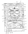
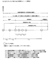
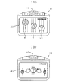
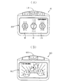
図1は、遊技機1の全体正面図、図2は、特別図柄表示装置6の正面図、図3は、遊技機1の下部正面図、図4は、遊技機1の裏側に設けられた遊技機制御装置100の要部ブロック図、図5は、遊技機制御装置100を構成する主制御回路44と表示制御回路111とを示すブロック図、図6は、遊技機制御装置100を構成する表示制御回路111と画像表示制御回路112とを示すブロック図である。
An embodiment of the present invention will be described below with reference to the drawings.
1 is an overall front view of the gaming machine 1, FIG. 2 is a front view of the special symbol display device 6, FIG. 3 is a lower front view of the gaming machine 1, and FIG. 4 is provided on the back side of the gaming machine 1. FIG. 5 is a block diagram showing a main control circuit 44 and a display control circuit 111 constituting the gaming machine control device 100, and FIG. 6 shows the gaming machine control device 100. 2 is a block diagram showing a display control circuit 111 and an image display control circuit 112. FIG.

本実施例の遊技機1は、図1に示すように、図示しない遊技島に固定される外枠22と、この外枠22に取り付けられた内枠23とから構成されており、内枠23には、遊技者にパチンコ遊技を提供する遊技盤21と、遊技者が操作することにより後述する打球発射装置43を作動させる打球操作ハンドル2と、打球発射装置43によって打ち出された遊技球を誘導する打球誘導レール3と、打ち出された遊技球が一定範囲内で飛球するよう設けられた遊技領域形成レール4と、打球誘導レール3及び遊技領域形成レール4によって囲われた遊技領域5と、遊技領域5に打ち出された遊技球を不測の方向へ変化を与える風車20と、特別図柄が回転する様子を示す擬似的な表示(以下、スクロール表示ともいう)を行う液晶表示ディスプレイ(LCD)等で構成された特別図柄表示装置6と、大当り演出画像、テレビ画像、ビデオ画像及び特別図柄表示装置6の表示を録画した画像(以下、単に録画画像ともいう)等の表示を行う液晶表示ディスプレイ(LCD)等で構成された画像表示装置80と、遊技球が入賞することによって特別図柄表示装置6に特別図柄の変動表示(スクロール表示)を開始させる始動入賞口(電動チューリップ)11と、特別図柄表示装置6が特別図柄の変動表示中に遊技球が始動入賞口11へ入賞した場合(以下、このような遊技球を保留球ともいう)に、当該変動表示が終了した後に、あと何回変動表示するか(最高4回)を遊技者に報知するための保留記憶の点灯表示を順次行う4つの保留LED25(25a、25b、25c、25d、図2参照)と、特別図柄表示装置6内において所定の画像を表示する画像表示部30と、この画像表示部30において3つの特別図柄をそれぞれ個別に表示する左図柄表示部8、中図柄表示部9、右図柄表示部10と、画像表示装置80内において所定の画像を表示する画像表示部81と、4つの保留LED25が全て点灯しているときに始動入賞口11へ入賞した遊技球(以下、このような遊技球をオーバーフロー球ともいう)の累積数を表示する7セグメントLED等で構成されたオーバーフロー球表示装置60と、特別図柄表示装置6における表示結果が予め定められた態様(大当り)になった場合、遊技者に有利に開口される大入賞口(アタッカ)7と、遊技球を打球発射装置43に供給するための打球供給皿12と、打球供給皿12に入りきらない球を貯留することができると共に、図示しない貯留球箱に遊技球を移動できるようになっている余剰球受皿13と、入賞することによって賞球が払い出される普通入賞口14と、入賞に対する賞球の払い出しや球詰まり、異常を報知する遊技効果ランプ15と、遊技領域5の最下部に設けられた遊技球を回収するアウト口16と、開閉自在に設け
られたガラス扉枠17と、一桁の普通図柄を表示し、その普通図柄が予め定められた普通図柄(当り)である場合、始動入賞口11としての電動チューリップの羽根を開放する7セグメントLED等で構成された普通図柄表示装置18と、遊技球が通過することによって普通図柄表示装置18に普通図柄の変動表示を開始させる普通図柄作動ゲート19と、普通図柄表示装置18が普通図柄の変動表示中に遊技球が普通図柄作動ゲート19を通過した場合(以下、このような遊技球を通過保留球ともいう)に、当該変動表示が終了した後に、あと何回変動表示するか(最高4回)を遊技者に報知するための保留記憶の点灯表示を順次行う4つの保留LED26(26a、26b、26c、26d、図2参照)と、外枠22の下部に設けられ、後述するヘッドセット31が接続されるヘッドセットジャック32、ヘッドセット31の音量を調節するボリューム摘み33、画像表示装置80にて表示されるテレビ画像のチャンネルを選択するチャンネルキー34及び画像表示装置80にて表示される画像をテレビ画像、ビデオ画像、録画画像の何れかに切り換える切り換えボタン35(図3参照)と、打球供給皿12の左上部に設けられ、画像表示装置80にて表示される録画画像の編集表示等を行うための保存ボタン70、再生ボタン71、送りボタン72、戻りボタン73、停止ボタン74及びポーズボタン75(図3参照)等とによって構成されている。
As shown in FIG. 1, the gaming machine 1 according to the present embodiment includes an outer frame 22 fixed to a game island (not shown) and an inner frame 23 attached to the outer frame 22. The game board 21 that provides the player with a pachinko game, the hitting operation handle 2 that operates the hitting ball launching device 43 to be described later when operated by the player, and the game ball launched by the hitting ball launching device 43 are guided. A striking ball guide rail 3 to be played, a game region forming rail 4 provided so that the launched game ball flies within a certain range, a game region 5 surrounded by the striking ball guiding rail 3 and the game region forming rail 4, A liquid crystal display that performs pseudo display (hereinafter also referred to as scroll display) showing a state in which a special symbol is rotated, and a windmill 20 that changes a game ball launched into the game area 5 in an unexpected direction. A special symbol display device 6 composed of an LCD) and the like, and a liquid crystal for displaying a jackpot effect image, a television image, a video image, an image recording the display of the special symbol display device 6 (hereinafter also simply referred to as a recorded image), and the like. An image display device 80 constituted by a display (LCD) or the like, and a start winning opening (electric tulip) 11 for causing the special symbol display device 6 to start a variable symbol display (scroll display) when the game ball wins. When the special symbol display device 6 displays the variation of the special symbol and the game ball wins the start winning opening 11 (hereinafter, such a game ball is also referred to as a holding ball), after the variation display ends, Four hold LEDs 25 (25a, 25b, 25c, 25d, see FIG. 2) that sequentially turn on and off the hold memory for informing the player of how many times to display the change (up to 4 times) ), An image display unit 30 for displaying a predetermined image in the special symbol display device 6, a left symbol display unit 8 for individually displaying three special symbols in the image display unit 30, a middle symbol display unit 9, The right symbol display unit 10, the image display unit 81 that displays a predetermined image in the image display device 80, and the game ball that won the start winning slot 11 when all four holding LEDs 25 are lit (hereinafter, this Such a game ball is also referred to as an overflow ball), and the display result on the overflow ball display device 60 composed of a 7-segment LED or the like for displaying the cumulative number and the special symbol display device 6 is in a predetermined mode (big hit). In this case, the player enters a winning opening (attacker) 7 that is advantageously opened to the player, a hitting ball supply tray 12 for supplying game balls to the hitting ball launching device 43, and a hitting ball supply tray 12. A non-illustrated ball can be stored and a game ball can be moved to a non-illustrated storage ball box, a surplus ball receiving tray 13, a normal winning port 14 where a winning ball is paid out by winning, and a winning A game effect lamp 15 for notifying a payout of a prize ball, a ball clogging, and an abnormality, an out port 16 for collecting game balls provided at the bottom of the game area 5, a glass door frame 17 provided to be openable and closable, A normal symbol display composed of a 7-segment LED or the like that opens the blades of the electric tulip as the start winning opening 11 when the normal symbol of one digit is displayed and the normal symbol is a predetermined normal symbol (winning). The normal symbol actuating gate 19 that causes the normal symbol display device 18 to start the variable symbol display when the game ball passes, and the normal symbol display device 18 are the normal symbols. When the game ball passes the normal symbol operation gate 19 during the fluctuation display (hereinafter, such a game ball is also referred to as a pass-holding ball), how many times the fluctuation display is performed after the fluctuation display is finished ( Four hold LEDs 26 (26a, 26b, 26c, 26d, see FIG. 2) for sequentially displaying the lighting of the hold memory for informing the player of (up to 4 times) and a lower part of the outer frame 22 will be described later. With a headset jack 32 to which the headset 31 is connected, a volume knob 33 for adjusting the volume of the headset 31, a channel key 34 for selecting a channel of a television image displayed on the image display device 80, and the image display device 80 A switching button 35 (see FIG. 3) for switching a displayed image to one of a TV image, a video image, and a recorded image, and a left upper portion of the hitting ball supply tray 12 In addition, a save button 70, a playback button 71, a feed button 72, a return button 73, a stop button 74, a pause button 75 (see FIG. 3), etc. for performing edit display of the recorded image displayed on the image display device 80, etc. And is composed of.

この様に構成される遊技機1は、まず、遊技者の打球操作ハンドル2の操作により、打球発射装置43から遊技球が発射され、打球誘導レール3と遊技領域形成レール4の間を通って遊技球が遊技盤21上の遊技領域5に打ち出される。そして、遊技球は遊技領域5を自重により落下し、落下する過程においては、遊技盤21に植設される図示しない遊技釘や風車20によって落下する方向に変化を与えられ、始動入賞口11や普通入賞口14に入賞したり、普通図柄作動ゲート19を通過したり、全ての入賞口に入賞しなかった場合には、アウト口16に回収されるようになっている。   In the gaming machine 1 configured as described above, first, a game ball is launched from the hit ball launching device 43 by the operation of the hitting operation handle 2 of the player, and passes between the hit ball guiding rail 3 and the game area forming rail 4. A game ball is launched into the game area 5 on the game board 21. Then, the game ball falls in the game area 5 by its own weight, and in the process of falling, the game ball 21 is changed in the direction of dropping by a game nail or a windmill 20 (not shown) implanted in the game board 21, In the case where the normal winning opening 14 is won, the normal symbol operating gate 19 is passed, or all the winning holes are not won, the winning hole 16 is collected.

遊技球が始動入賞口11に入賞した場合には、所定の賞品球を遊技者に与えると共に、後述する始動入賞検出センサ116によって遊技球を検出し、特別図柄表示装置6の各図柄表示部8、9、10に特別図柄をスクロール表示させ、所定時間後に左図柄表示部8、右図柄表示部10、中図柄表示部9の順に特別図柄を停止させて抽選を行い、左図柄表示部8の特別図柄と右図柄表示部10の特別図柄とが停止した時点で大当りを構成する特別図柄の組合せ(例えば同一の特別図柄の組合せ)である場合にはリーチとなり、特別図柄表示装置6の画像表示部30にて所定のリーチアクションが表示されるようになっており、その後中図柄表示部9の特別図柄が停止した時点で確定表示された特別図柄が予め定められた特別図柄の組合せである場合には大当りとなり、大入賞口7としてのアタッカを所定の態様で開放する大当り遊技が実行されると共に、画像表示装置80の画像表示部81には、後に詳述するが、オーバーフロー球表示装置60に表示されているオーバーフロー球の累積数に基づいて所定の大当り演出画像が優先的に表示されるようになっており、これら以外の特別図柄の組合せである場合には、はずれとなる。   When the game ball wins the start winning opening 11, a predetermined prize ball is given to the player, and the game ball is detected by a start winning detection sensor 116 described later, and each symbol display unit 8 of the special symbol display device 6 is detected. , 9 and 10, the special symbols are scroll-displayed, and after a predetermined time, the special symbols are stopped in the order of the left symbol display unit 8, the right symbol display unit 10, and the middle symbol display unit 9, and a lottery is performed. When the special symbol and the special symbol on the right symbol display unit 10 are stopped, a special symbol combination (for example, the same special symbol combination) that constitutes a big hit is reached, and the special symbol display device 6 displays an image. A predetermined reach action is displayed in the part 30, and then the special symbol that is confirmed and displayed when the special symbol in the middle symbol display unit 9 is stopped is a combination of predetermined special symbols. In this case, a big hit game is executed to open the attacker as the big winning opening 7 in a predetermined manner, and the image display unit 81 of the image display device 80 will be described in detail later. A predetermined jackpot effect image is preferentially displayed based on the cumulative number of overflow spheres displayed at 60, and if the combination is a special symbol other than these, it is out of place.

なお、画像表示装置80の画像表示部81には、大当り演出画像が表示されないときは、遊技者が切り換えボタン35を押圧操作することによりテレビ画像、ビデオ画像または録画画像の何れかが表示されるようになっている。テレビ画像は、遊技者がチャンネルキー34を押圧操作することにより、遊技者の所望するチャンネルのテレビ画像が表示される。また、ビデオ画像は、予め遊技場が用意しているもので、例えば遊技機1の遊技説明や遊技場の宣伝広告等の画像が表示される。また、録画画像は、後に詳述するが、特別図柄表示装置6にて表示された変動表示の画像が自動的に更新されて所定回数分だけ録画されるようになっており、さらに遊技者が保存ボタン70を押圧操作することにより、遊技者の所望する録画画像が保存されるようになっている。そして、遊技者が再生ボタン71、送りボタン72、戻りボタン73、停止ボタン74またはポーズボタン75を押圧操作することにより、この保存した録画画像または自動的に更新される録画画像が、遊技者の
所望する態様にて編集表示される。なお、テレビ画像、ビデオ画像または録画画像の音声は、ヘッドセットジャック32に接続した後述するヘッドセット31により聞くことができるようになっており、その音量は、ボリューム摘み33を左右に回動操作することで調節できるようになっている。
Note that, when the big hit effect image is not displayed, any one of the television image, the video image, and the recorded image is displayed on the image display unit 81 of the image display device 80 when the player presses the switching button 35. It is like that. A television image of a channel desired by the player is displayed when the player presses the channel key 34. In addition, the video image is prepared in advance by the game hall, and for example, an image such as a game description of the gaming machine 1 or an advertisement for the game hall is displayed. As will be described in detail later, the recorded image is automatically updated by the variable display image displayed on the special symbol display device 6 and recorded for a predetermined number of times. By pressing the save button 70, a recorded image desired by the player is saved. Then, when the player presses the play button 71, the feed button 72, the return button 73, the stop button 74 or the pause button 75, the stored recorded image or the automatically updated recorded image becomes the player's Edited and displayed in a desired manner. The sound of the television image, the video image or the recorded image can be heard by a headset 31 which will be described later connected to the headset jack 32. The volume of the sound can be adjusted by rotating the volume knob 33 left and right. It can be adjusted by doing.

また、遊技球が普通入賞口14に入賞した場合には、所定の賞品球が遊技者に与えられる。また、遊技球が普通図柄作動ゲート19を通過した場合には、後述する作動ゲート検出センサ121によって遊技球を検出し、普通図柄表示装置18に普通図柄を変動表示させて抽選を行い、確定表示された普通図柄が予め定められた普通図柄である場合には当りとなり、始動入賞口(電動チューリップ)11の羽根を所定時間開放するようなっている。   Further, when the game ball wins the normal winning opening 14, a predetermined prize ball is given to the player. When the game ball passes the normal symbol operation gate 19, the game ball is detected by an operation gate detection sensor 121, which will be described later, the normal symbol is variably displayed on the normal symbol display device 18, and a lottery is performed to confirm the display. When the normal symbol is a normal symbol determined in advance, it is a win and the blades of the start winning opening (electric tulip) 11 are opened for a predetermined time.

次に遊技機1の裏側に設けられた遊技機制御装置100を図4を用いて説明する。
遊技機制御装置100は図4に示すように構成され、遊技機制御装置100を主に構成する主制御回路44は、入力回路101、出力回路110、ワンチップマイクロコンピュータ27及びこれらを接続するバス115(データバス、アドレスバス、コントロールバス等)とを備えており、入力回路101を介して取得した各センサやスイッチからの信号に基づいて、ワンチップマイクロコンピュータ27が出力回路110に接続されている各種回路や機器等を制御するための所定の制御プログラムを実行する。また、ワンチップマイクロコンピュータ27は、制御プログラムを実行するCPU102、CPU102が実行する制御プログラムを格納するROM103及びCPU102が処理するデータを一時的に記憶するRAM104が内蔵されている。
Next, the gaming machine control device 100 provided on the back side of the gaming machine 1 will be described with reference to FIG.
The gaming machine control device 100 is configured as shown in FIG. 4, and the main control circuit 44 mainly constituting the gaming machine control device 100 includes an input circuit 101, an output circuit 110, a one-chip microcomputer 27, and a bus connecting them. 115 (data bus, address bus, control bus, etc.), and the one-chip microcomputer 27 is connected to the output circuit 110 on the basis of signals from the sensors and switches acquired via the input circuit 101. A predetermined control program for controlling various circuits and devices is executed. The one-chip microcomputer 27 includes a CPU 102 that executes a control program, a ROM 103 that stores a control program executed by the CPU 102, and a RAM 104 that temporarily stores data processed by the CPU 102.

入力回路101には、始動入賞口11に設けられた遊技球の入賞を検出すると特別図柄変動開始信号(以下、始動信号ともいう)を送る始動入賞検出センサ116と、始動入賞口11に入賞した遊技球数を検出するカウントスイッチ123と、普通図柄作動ゲート19に設けられた遊技球の通過を検出すると普通図柄変動開始信号(以下、作動信号ともいう)を送る作動ゲート検出センサ121と、大入賞口7を開放することにより大入賞口7内に入賞した遊技球数を検出するカウントスイッチ117と、大入賞口7の特定領域を通過した遊技球を検出する継続入賞スイッチ118と、打球操作ハンドル2が回動操作されて遊技球が発射される時にオンする打球操作ハンドルスイッチ119と、打球操作ハンドル2の所定箇所に設けられ押圧操作することにより打球発射装置43の作動をオフさせて遊技球の発射を停止する打球操作ストップスイッチ120と、各入賞口に入賞した遊技球をセーフ球としてカウントし遊技球を賞品として払い出すために必要なセーフ信号を出力するセーフ球検出センサ122とが接続されている。   When the winning of the game ball provided in the start winning opening 11 is detected in the input circuit 101, a start winning detection sensor 116 that sends a special symbol variation start signal (hereinafter also referred to as a start signal), and the start winning opening 11 is won. A count switch 123 for detecting the number of game balls, an operation gate detection sensor 121 for sending a normal symbol variation start signal (hereinafter also referred to as an operation signal) when the passage of a game ball provided in the normal symbol operation gate 19 is detected, A count switch 117 for detecting the number of game balls won in the big prize opening 7 by opening the prize opening 7, a continuous prize switch 118 for detecting a game ball that has passed a specific area of the big prize opening 7, and a hitting operation A hitting operation switch 119 that is turned on when the handle 2 is turned and a game ball is fired, and a press provided at a predetermined position of the hitting operation handle 2 In order to turn off the operation of the hitting ball launching device 43 to stop the launching of the game ball, and to count the game balls won in each winning opening as safe balls and to pay out the game balls as prizes Is connected to a safe sphere detection sensor 122 that outputs a safe signal necessary for the operation.

出力回路110には、遊技盤面に配備されているLED(例えば、保留LED25や保留LED26)や各種表示ランプ(例えば、遊技効果ランプ15)等を点灯/点滅制御するランプ制御回路37と、大入賞口7としてのアタッカを開口動作するためのソレノイド106と、始動入賞口11としての電動チューリップを開放動作するためのソレノイド107と、スピーカ113より各種の効果音を拡声させるための音声制御を行う音声制御回路38と、図示しないホール管理コンピュータ等に接続される外部情報端子109とが接続されている。また、出力回路110には、図示しないドライバ回路を経由して普通図柄表示装置(7セグLED)18及びオーバーフロー球表示装置(7セグLED)60が接続されている。なお、図4では省略されているが、音声制御回路38からの各種効果音に係わる出力は、後述する画像表示制御回路112にも入力されるようになっている(後述する図6参照)。   The output circuit 110 includes a lamp control circuit 37 that controls lighting / flashing of LEDs (for example, the hold LED 25 and the hold LED 26) and various display lamps (for example, the game effect lamp 15) provided on the game board surface, and a grand prize. A solenoid 106 for opening the attacker as the mouth 7, a solenoid 107 for opening the electric tulip as the start winning opening 11, and a voice for performing voice control for amplifying various sound effects from the speaker 113. The control circuit 38 is connected to an external information terminal 109 connected to a hall management computer or the like (not shown). In addition, a normal symbol display device (7-segment LED) 18 and an overflow ball display device (7-segment LED) 60 are connected to the output circuit 110 via a driver circuit (not shown). Although omitted in FIG. 4, outputs related to various sound effects from the sound control circuit 38 are also input to an image display control circuit 112 described later (see FIG. 6 described later).

さらに、出力回路110には、払出制御回路40及び表示制御回路111が接続されている。払出制御回路40は、内部に払出制御用CPU(図示せず)、この払出制御用CP
Uの作業領域や各賞球コマンドに対応した賞品球数等を記憶保持するための記憶エリアを備えたRAM及び制御データ及び賞球払出しのための制御プログラム等が記憶されたROMなどを備えている。払出制御回路40は、主制御回路44のCPU102から指令される賞球コマンドに従って賞球払出装置41を駆動制御し、賞品球の払出制御を行う。払出制御回路40には、その他、発射制御回路42を介して遊技領域5に向けてパチンコ球を弾発するための打球発射装置43が接続されており、打球発射装置43の動作停止と動作停止解除とを制御する。
Furthermore, the payout control circuit 40 and the display control circuit 111 are connected to the output circuit 110. The payout control circuit 40 includes a payout control CPU (not shown) and a payout control CP.
A RAM having a storage area for storing and holding the U work area and the number of prize balls corresponding to each prize ball command, and a ROM in which control data, a control program for paying out a prize ball, and the like are stored. Yes. The payout control circuit 40 drives and controls the prize ball payout device 41 according to the prize ball command instructed from the CPU 102 of the main control circuit 44, and performs prize ball payout control. In addition, the payout control circuit 40 is connected to a hitting ball launching device 43 for emitting a pachinko ball toward the game area 5 via the launching control circuit 42. And control.

次に、図5を参照して表示制御回路111について説明する。図5に示すように、表示制御回路111は、主制御回路44の出力回路110から一方向のストローブ信号や表示制御用コマンド信号等の制御信号が入力されることにより、特別図柄表示装置6の画像表示部30にて表示する2次元や3次元のスクロール表示等に係わる画像処理のための表示制御を実行すると共に、後述する画像表示制御回路112に大当り演出画像及び録画画像に係わる画像データを出力する。このため、表示制御回路111は、CPU140と、RAM141と、ROM142と、VDP143と、VRAM(ビデオRAM)144と、キャラクタROM145と、入力インターフェース146と、リセット回路147と、発振回路148と、タイミングコントローラ149と、LCD駆動回路150とを備えている。   Next, the display control circuit 111 will be described with reference to FIG. As shown in FIG. 5, the display control circuit 111 receives a control signal such as a one-way strobe signal or a display control command signal from the output circuit 110 of the main control circuit 44. In addition to executing display control for image processing related to 2D or 3D scroll display displayed on the image display unit 30, image data related to the jackpot effect image and the recorded image is transmitted to the image display control circuit 112 described later. Output. Therefore, the display control circuit 111 includes a CPU 140, a RAM 141, a ROM 142, a VDP 143, a VRAM (video RAM) 144, a character ROM 145, an input interface 146, a reset circuit 147, an oscillation circuit 148, and a timing controller. 149 and an LCD drive circuit 150.

入力インターフェース146は、例えば入力端が抵抗を介して電源に接続されたトランジスタアレイ等で構成された図示しないバッファ回路が設けられており、主制御回路44から入力されたストローブ信号と表示制御用コマンド信号をCPU140のINT端子(図示省略)に出力する。これにより、主制御回路44から表示制御回路111への信号入力のみを許容し、表示制御回路111から主制御回路44への信号出力を禁止している。なお、この表示制御用コマンドについては、図33に示し後述する。発振回路148は、CPU140とVDP143とに基準クロック信号を出力する回路であり、リセット回路147は、CPU140とVDP143とをリセットするためのリセット信号を出力する回路である。CPU140とVDP143は、発振回路148からの基準クロック信号を分周して内部クロック信号を生成し、この内部クロック信号に基づいて動作する。   The input interface 146 is provided with a buffer circuit (not shown) composed of, for example, a transistor array whose input terminal is connected to a power source via a resistor. The strobe signal input from the main control circuit 44 and the display control command are provided. The signal is output to an INT terminal (not shown) of the CPU 140. Thus, only signal input from the main control circuit 44 to the display control circuit 111 is permitted, and signal output from the display control circuit 111 to the main control circuit 44 is prohibited. This display control command is shown in FIG. 33 and will be described later. The oscillation circuit 148 is a circuit that outputs a reference clock signal to the CPU 140 and the VDP 143, and the reset circuit 147 is a circuit that outputs a reset signal for resetting the CPU 140 and the VDP 143. The CPU 140 and the VDP 143 divide the reference clock signal from the oscillation circuit 148 to generate an internal clock signal, and operate based on the internal clock signal.

ROM142は、CPU140によって実行される表示制御プログラムを記憶する半導体メモリであり、RAM141は、CPU140によって実行される表示制御プログラムのワークエリアやスタックエリア等の作業領域として利用される半導体メモリである。CPU140は、表示制御プログラムを実行する中央演算装置であり、入力インターフェース146からストローブ信号が入力されると表示制御用コマンド信号を認識してRAM141を作業領域としてROM142から表示制御を行うための制御データを読み出し、2次元の図柄表示情報、動画キャラクタ画面情報や背景画面情報、3次元画像情報(オブジェクト)の座標演算(ジオメトリ演算)等の画像データの演算を行うと共に描画コマンドを作成し、これら画像データの演算結果及び作成した描画コマンドをRAM141に格納し、VDP143に制御信号として出力する。   The ROM 142 is a semiconductor memory that stores a display control program executed by the CPU 140, and the RAM 141 is a semiconductor memory that is used as a work area such as a work area or a stack area of the display control program executed by the CPU 140. The CPU 140 is a central processing unit that executes a display control program. When a strobe signal is input from the input interface 146, the CPU 140 recognizes a display control command signal and controls the display data from the ROM 142 using the RAM 141 as a work area. 2D symbol display information, animation character screen information, background screen information, 3D image information (object) coordinate calculation (geometry calculation) and other image data calculations and drawing commands are created. The calculation result of the data and the created drawing command are stored in the RAM 141 and output to the VDP 143 as a control signal.

なお、この描画コマンドの具体例としては、例えばアトリビュートコマンド、スプライトコマンド、スプラインコマンド、ポリゴン表示コマンド、テクスチャマッピングコマンド等が挙げられる。   Specific examples of the drawing command include an attribute command, a sprite command, a spline command, a polygon display command, a texture mapping command, and the like.

キャラクタROM145は、例えばフラッシュROM等で構成され、キャラクタや図柄、背景、動画キャラクタ等の2次元データやオブジェクトデータやテクスチャデータ等の3次元データ等の画像データが記憶された半導体メモリであり、また、VRAM144は、VDP143が処理する画像データを一時的に記憶して展開するためのフレームバッファメモリである。VDP143は、CPU140からの制御信号に基づき、特別図柄表示
装置6の画像表示部30及び画像表示装置80の画像表示部81に表示する変動表示及び大当り演出画像等の画像データを生成するもので、CPU140とは独立した2次元のアドレス空間を持ち、そこにVRAM144をマッピングしている。
The character ROM 145 is constituted by, for example, a flash ROM or the like, and is a semiconductor memory in which image data such as two-dimensional data such as a character, a pattern, a background, and a moving image character, or three-dimensional data such as object data and texture data is stored. The VRAM 144 is a frame buffer memory for temporarily storing and developing image data processed by the VDP 143. Based on the control signal from the CPU 140, the VDP 143 generates image data such as a variable display and a jackpot effect image displayed on the image display unit 30 of the special symbol display device 6 and the image display unit 81 of the image display device 80. A two-dimensional address space independent of the CPU 140 is provided, and the VRAM 144 is mapped there.

また、VDP143は、タイミングコントローラ149を備えており、VRAM144に展開した画像データ(大当り演出画像データを除く)を一定周期毎にLCD駆動回路150に供給する。つまり、タイミングコントローラ149は、発振回路148からの基準クロック信号及びリセット回路147からのリセット信号に基づいて、LCD駆動回路150に供給する同期信号(水平同期信号、垂直同期信号、クロック信号)を出力するものであり、LCD駆動回路150は、VDP143から供給された画像データ(大当り演出画像データを除く)を、色信号と輝度信号とからなるビデオ信号に変換し、このビデオ信号の波形をLCDとしての特別図柄表示装置6に適合した波形に整形することにより振幅調整、ガンマ補正、コントラスト、ブライト調整等を行い、特別図柄表示装置6に出力する。   The VDP 143 includes a timing controller 149, and supplies image data (excluding the big hit effect image data) developed in the VRAM 144 to the LCD drive circuit 150 at regular intervals. That is, the timing controller 149 outputs a synchronization signal (horizontal synchronization signal, vertical synchronization signal, clock signal) to be supplied to the LCD drive circuit 150 based on the reference clock signal from the oscillation circuit 148 and the reset signal from the reset circuit 147. The LCD drive circuit 150 converts the image data (except for the big hit effect image data) supplied from the VDP 143 into a video signal composed of a color signal and a luminance signal, and the waveform of the video signal is used as an LCD. Are adjusted to a waveform suitable for the special symbol display device 6 to perform amplitude adjustment, gamma correction, contrast, brightness adjustment, and the like, and output to the special symbol display device 6.

ここで、本実施例に係わるLCD駆動回路150は、NTSC方式に準拠したビデオ信号を出力するようになっており、水平同期信号(水平帰線)は63.5μ秒毎に出力され、垂直同期信号(垂直帰線)は1/30秒毎(ノンインターレース)に出力されるようになっている(但し、インターレースの場合には、垂直同期信号は1/60秒毎に出力されるが、本実施例においては、以後ノンインターレースの場合についてのみ説明する)。   Here, the LCD driving circuit 150 according to the present embodiment outputs a video signal conforming to the NTSC system, and a horizontal synchronizing signal (horizontal blanking) is output every 63.5 μsec. The signal (vertical blanking) is output every 1/30 seconds (non-interlace) (however, in the case of interlace, the vertical sync signal is output every 1/60 seconds. In the embodiment, only the case of non-interlace will be described hereinafter).

つまり、VDP143は、タイミングコントローラ149から垂直同期信号が入力される毎(1/30秒毎)に、VRAM144に展開した画像データ(大当り演出画像データを除く)を内部クロック信号に基づいて順次LCD駆動回路150に供給し、LCD駆動回路150は、供給された画像データ(大当り演出画像データを除く)をビデオ信号に変換して波形整形し、この波形整形したビデオ信号を水平同期信号に基づいて1フレームの画像を特別図柄表示装置6の画像表示部30に表示する。そしてLCD駆動回路150は、垂直同期信号が入力される毎(1/30秒毎)に、特別図柄表示装置6の画像表示部30に表示する1フレームの画像を切り換え、これにより変動表示としてのスクロール表示やリーチアクション等の動画が表示される。また、VDP143は、タイミングコントローラ149から垂直同期信号を受信する毎(1/30秒毎)に、CPU140のINT端子(図示省略)に割込み信号を出力する。CPU140は、この割込み信号を受信することにより、次回の1フレームの画像を作成するための表示制御を内部クロック信号に基づいて実行する。   That is, the VDP 143 sequentially drives the image data (excluding the big hit effect image data) developed in the VRAM 144 based on the internal clock signal every time a vertical synchronization signal is input from the timing controller 149 (every 1/30 seconds). The LCD driving circuit 150 converts the supplied image data (except for the big hit effect image data) into a video signal, shapes the waveform, and converts the waveform-shaped video signal to 1 based on the horizontal synchronization signal. The frame image is displayed on the image display unit 30 of the special symbol display device 6. The LCD driving circuit 150 switches the image of one frame displayed on the image display unit 30 of the special symbol display device 6 every time a vertical synchronizing signal is input (every 1/30 seconds), thereby changing the display as a variable display. Videos such as scroll display and reach action are displayed. The VDP 143 outputs an interrupt signal to the INT terminal (not shown) of the CPU 140 every time a vertical synchronization signal is received from the timing controller 149 (every 1/30 seconds). By receiving this interrupt signal, the CPU 140 executes display control for creating the next one-frame image based on the internal clock signal.

なお、VDP143は、一定周期毎(タイミングコントローラ149から垂直同期信号が入力される1/30秒毎)に、後述する画像表示制御回路112の録画用のVRAM166に、VRAM144に展開した画像データのうち録画画像に係わる変動表示の画像データをコピーすると共に、後述する画像表示制御回路112のLCD駆動回路167に、VRAM144に展開した画像データのうち大当り遊技に係わる大当り演出画像の画像データを、上記LCD駆動回路150と同様に供給するようになっている。   Note that the VDP 143 is stored in the VRAM 166 for recording of the image display control circuit 112 (described later) in the VRAM 144 at regular intervals (every 1/30 seconds when the vertical synchronization signal is input from the timing controller 149). The image data of the variable display related to the recorded image is copied, and the image data of the big hit effect image related to the big hit game among the image data developed in the VRAM 144 is transferred to the LCD drive circuit 167 of the image display control circuit 112 described later. It is supplied in the same manner as the drive circuit 150.

次に、図6を参照して画像表示制御回路112について説明する。図6に示すように、画像表示制御回路112は、画像表示装置80の画像表示部81にテレビ画像、ビデオ画像、録画画像または大当り演出画像を表示する機能を有しており、受信回路160と、入力バッファ161と、CPU162と、ROM163と、RAM164と、コントローラ165と、VRAM(ビデオRAM)166と、LCD駆動回路167とを備えている。   Next, the image display control circuit 112 will be described with reference to FIG. As shown in FIG. 6, the image display control circuit 112 has a function of displaying a television image, a video image, a recorded image, or a jackpot effect image on the image display unit 81 of the image display device 80. , An input buffer 161, a CPU 162, a ROM 163, a RAM 164, a controller 165, a VRAM (video RAM) 166, and an LCD drive circuit 167.

まず入力バッファ161には、後述するヘッドセット31にて聞くテレビ画像、ビデオ画像または録画画像の音量を調節するボリューム摘み33と、後述するテレビチューナ8
5のチャンネルを切り換えるチャンネルキー34と、画像表示装置80の出力モードをテレビモード、ビデオモードまたは録画モードの何れかに設定する切り換えボタン35と、スピーカ113から拡声される各種効果音を入力する音声制御回路38と、録画画像のうち遊技者が所望する変動表示の画像データが更新されないように保存する保存ボタン70と、録画画像を画像表示装置80の画像表示部81に表示する再生ボタン71と、録画画像を早送りやコマ送りする送りボタン72と、録画画像を巻き戻しや逆コマ送りする戻りボタン73と、画像表示部81における録画画像の再生表示を停止する停止ボタン74と、画像表示部81における録画画像の再生表示を一時停止するポーズボタン75とが接続されている。
First, the input buffer 161 includes a volume knob 33 for adjusting the volume of a television image, a video image, or a recorded image heard by a headset 31 described later, and a television tuner 8 described later.
A channel key 34 for switching the channel 5, a switching button 35 for setting the output mode of the image display device 80 to one of the television mode, the video mode, and the recording mode, and a sound for inputting various sound effects amplified from the speaker 113. A control circuit 38, a save button 70 for saving the image data of the variable display desired by the player among the recorded images, and a playback button 71 for displaying the recorded images on the image display unit 81 of the image display device 80. , A forward button 72 for fast-forwarding or frame-by-frame the recorded image, a return button 73 for rewinding or reverse-frame-recording the recorded image, a stop button 74 for stopping playback display of the recorded image on the image display unit 81, and an image display unit A pause button 75 for temporarily stopping the playback display of the recorded image at 81 is connected.

受信回路160は、管理室等、遊技場内の所定場所に設置される送信装置87と接続されており、テレビチューナ85から出力されるテレビ画像信号とビデオ装置86から出力されるビデオ画像信号、及びそれらに伴う音声信号を送信装置87を介して受信する。VRAM166は、VDP143から出力された録画画像に係わる変動表示の画像データを記憶するためのフレームバッファメモリである。CPU162は、画像表示装置80の画像表示制御プログラムを実行する中央演算装置であり、入力バッファ161から入力される各種信号に基づき、RAM164を作業領域としてROM163から画像表示制御を行うための画像制御データを読み出し、その演算結果をRAM164に格納すると共にコントローラ165に制御信号として出力する。   The receiving circuit 160 is connected to a transmitting device 87 installed at a predetermined place in the game room such as a management room, and receives a TV image signal output from the TV tuner 85 and a video image signal output from the video device 86, and The accompanying audio signal is received via the transmitter 87. The VRAM 166 is a frame buffer memory for storing image data of variable display related to the recorded image output from the VDP 143. The CPU 162 is a central processing unit that executes an image display control program of the image display device 80, and based on various signals input from the input buffer 161, image control data for performing image display control from the ROM 163 using the RAM 164 as a work area. Is stored in the RAM 164 and output to the controller 165 as a control signal.

コントローラ165は、CPU162からの制御信号に基づいて次のような制御を実行する。まず、切り換えボタン35からの信号に基づき、テレビ画像、ビデオ画像または録画画像の画像データをLCD駆動回路167に、音声データをアンプ88にそれぞれ供給する。つまり、切り換えボタン35がテレビモードに設定されている場合には、受信回路160から受信したテレビ画像信号及び音声信号を、チャンネルキー34に応じてLCD駆動回路167及びアンプ88にそれぞれ出力する。また、切り換えボタン35がビデオモードに設定されている場合には、受信回路160から受信したビデオ画像信号及び音声信号を、LCD駆動回路167及びアンプ88にそれぞれ出力する。   The controller 165 executes the following control based on the control signal from the CPU 162. First, based on the signal from the switching button 35, image data of a television image, a video image or a recorded image is supplied to the LCD drive circuit 167, and audio data is supplied to the amplifier 88. That is, when the switching button 35 is set to the television mode, the television image signal and the audio signal received from the receiving circuit 160 are output to the LCD driving circuit 167 and the amplifier 88 according to the channel key 34, respectively. When the switching button 35 is set to the video mode, the video image signal and the audio signal received from the receiving circuit 160 are output to the LCD driving circuit 167 and the amplifier 88, respectively.

また、切り換えボタン35が録画モードに設定されている場合には、再生ボタン71、送りボタン72、戻りボタン73、停止ボタン74またはポーズボタン75からの信号に基づき、VRAM166に記憶されている録画画像の画像データをLCD駆動回路167に出力すると共に、この画像データに対応するRAM164に記憶した音声制御回路38からの効果音データをアンプ88に出力する。ここで、上記したようにVRAM166には、変動表示の画像データが自動的に更新されて常時直前の10回の変動表示分だけ記憶されるようになっており、その記憶される変動表示に対応して効果音データがRAM164に記憶されるようになっている。そして保存ボタン70からの信号に基づき、VRAM166及びRAM164に記憶された変動表示の画像データ及び効果音データの中から所定のデータが選択され、この選択された変動表示の画像データ及び効果音データがVRAM166及びRAM164の保存用記憶エリアに格納される。つまり、録画画像は、自動的に更新される変動表示の画像データ及び効果音データと、遊技者が保存ボタン70を介して記憶保存した変動表示の画像データ及び効果音データとから成る。   When the switching button 35 is set to the recording mode, the recorded image stored in the VRAM 166 is based on signals from the play button 71, the feed button 72, the return button 73, the stop button 74, or the pause button 75. Is output to the LCD drive circuit 167, and the sound effect data from the sound control circuit 38 stored in the RAM 164 corresponding to the image data is output to the amplifier 88. Here, as described above, the image data of the variable display is automatically updated in the VRAM 166 so as to be always stored for the immediately preceding ten variable displays, and corresponding to the stored variable display. Thus, the sound effect data is stored in the RAM 164. Based on the signal from the save button 70, predetermined data is selected from the fluctuation display image data and sound effect data stored in the VRAM 166 and RAM 164, and the selected fluctuation display image data and sound effect data are stored in the selected data. It is stored in the storage area for storage of the VRAM 166 and RAM 164. In other words, the recorded image is made up of automatically displayed variable display image data and sound effect data, and variable display image data and sound effect data stored and saved by the player via the save button 70.

なお、アンプ88には、ヘッドセットジャック32を介してヘッドセット31が接続されており、ヘッドセット31の音量はボリューム摘み33からの信号に基づいて調節される。   The headset 88 is connected to the amplifier 88 via the headset jack 32, and the volume of the headset 31 is adjusted based on the signal from the volume knob 33.

LCD駆動回路167は、表示制御回路111のタイミングコントローラ149と接続され、上記した表示制御回路111のLCD駆動回路150と同様、NTSC方式に準拠したビデオ信号を出力する構成になっており、コントローラ165から供給された画像デ
ータに基づいて画像表示装置80にテレビ画像、ビデオ画像または録画画像を表示する。また、LCD駆動回路167には、タイミングコントローラ149から垂直同期信号が入力される毎(1/30秒毎)に、VRAM144に展開した大当り演出画像データがVDP143より入力され、この場合LCD駆動回路167は、切り換えボタン35のモード設定に関係なく、優先して画像表示装置80に大当り演出画像を表示する。また、LCD駆動回路167は、タイミングコントローラ149から垂直同期信号を受信する毎(1/30秒毎)に、コントローラ165を介してCPU162のINT端子(図示省略)に割込み信号を出力する。CPU162は、この割込み信号を受信することにより、ROM163に記憶した画像表示制御を内部クロック信号に基づいて繰り返し実行する。
The LCD drive circuit 167 is connected to the timing controller 149 of the display control circuit 111 and, like the LCD drive circuit 150 of the display control circuit 111 described above, outputs a video signal conforming to the NTSC system. A television image, a video image, or a recorded image is displayed on the image display device 80 based on the image data supplied from. Further, every time a vertical synchronizing signal is input from the timing controller 149 (every 1/30 seconds), the big hit effect image data developed in the VRAM 144 is input from the VDP 143 to the LCD drive circuit 167. In this case, the LCD drive circuit 167 Displays a big hit effect image on the image display device 80 with priority regardless of the mode setting of the switching button 35. The LCD driving circuit 167 outputs an interrupt signal to the INT terminal (not shown) of the CPU 162 via the controller 165 every time a vertical synchronization signal is received from the timing controller 149 (every 1/30 seconds). By receiving this interrupt signal, the CPU 162 repeatedly executes the image display control stored in the ROM 163 based on the internal clock signal.

なお、上記したRAM141またはRAM164は、CPU140またはCPU162に対し外付けするようにしたが、これは限定することなく、CPU140またはCPU162に内蔵して設けるようにしても良い。   The RAM 141 or the RAM 164 described above is externally attached to the CPU 140 or the CPU 162, but this is not limited, and the RAM 141 or the RAM 164 may be provided in the CPU 140 or the CPU 162.

また、上記した主制御回路44は、図5に示すように、電源が切られた場合でもRAM104の記憶内容を保持可能なRAMバックアップ130の回路を有しており、さらに、外部から主制御回路44の内容等を試験するための試験用端子131、例えばコネクタ等も備えている。   Further, as shown in FIG. 5, the main control circuit 44 has a RAM backup 130 circuit that can retain the stored contents of the RAM 104 even when the power is turned off. A test terminal 131 for testing the contents of 44, for example, a connector is also provided.

このように、主制御回路44のRAM104が、電源が切られた場合でも記憶内容を保持可能なバックアップ機能を有していると、例えば、雷が近くで発生してサージ電流が遊技機1内に侵入したり等して、突然遊技機1の電源が遮断されても、主制御回路44のRAM104が記憶した遊技に係わるデータが全て保全されるので、遊技機1の電源が回復されたときには、以前の遊技状態から引き続き遊技を再開でき、遊技場は公正な遊技を遊技者に提供でき、一方遊技者は、例えば、有利な遊技状態で電源が遮断された場合であっても、電源が復帰後、有利な遊技状態を引き続き続行することが可能となるので不測の不利益を回避でき、双方にとって顕著な効果を奏する。なお、このバックアップ機能は、主制御回路44のRAM104以外に、上記した賞品球の払出を司る払出制御回路40のRAM等、その他の制御回路のRAMにも設けても良い。   Thus, if the RAM 104 of the main control circuit 44 has a backup function that can retain the stored contents even when the power is turned off, for example, lightning occurs nearby and a surge current is generated in the gaming machine 1. Even if the gaming machine 1 is suddenly shut down due to intrusion etc., all the data related to the game stored in the RAM 104 of the main control circuit 44 is maintained, so when the power of the gaming machine 1 is restored , The game can continue to resume from the previous gaming state, and the game arcade can provide a fair game to the player, while the player may be powered off even if the power is interrupted, for example, in an advantageous gaming state. After returning, it becomes possible to continue the advantageous gaming state, so that an unexpected disadvantage can be avoided, and a remarkable effect is exerted on both sides. In addition to the RAM 104 of the main control circuit 44, this backup function may be provided in the RAM of other control circuits such as the RAM of the payout control circuit 40 that controls the payout of prize balls.

また、主制御回路44のCPU102から表示制御回路111へ制御信号(ストローブ信号やコマンド信号等)を一方向通信することにより、即ち、表示制御回路111から主制御回路44への入力をなくすことにより、遊技機1全体の主な制御を司る主制御回路44への入力を少なくして、主制御回路44への不正な信号入力を極力排除でき、遊技場は適正な遊技を遊技者に提供できると共に、両者の通信に係わる回路構成やプログラムを簡素化でき、遊技機1を開発制作するうえで容易となりコストダウンにつながるという顕著な効果を奏する。なお、この主制御回路44のCPU102からの一方向通信は、表示制御回路111以外に、図4に示すような賞品球の払出を司る払出制御回路40等、その他の制御回路にも行うようになっている。   Further, the control signal (strobe signal, command signal, etc.) is unidirectionally communicated from the CPU 102 of the main control circuit 44 to the display control circuit 111, that is, by eliminating the input from the display control circuit 111 to the main control circuit 44. The number of inputs to the main control circuit 44 that controls the main control of the entire gaming machine 1 can be reduced, and illegal signal inputs to the main control circuit 44 can be eliminated as much as possible, and the game field can provide appropriate games to the player. At the same time, it is possible to simplify the circuit configuration and the program related to the communication between the two, and it is easy to develop and produce the gaming machine 1 and has a remarkable effect that leads to cost reduction. In addition to the display control circuit 111, the one-way communication from the CPU 102 of the main control circuit 44 is also performed to other control circuits such as a payout control circuit 40 that controls payout of prize balls as shown in FIG. It has become.

なお、主制御回路44の出力回路110に直接接続した普通図柄表示装置18、ランプ制御回路37、音声制御回路38及びオーバーフロー球表示装置60は、表示制御回路111や画像表示制御回路112或いは払出制御回路40に接続するようにしても良い。さらに、入力回路101に接続した打球操作ハンドルスイッチ119と打球操作ストップスイッチ120は、発射制御回路42或いは払出制御回路40に直接接続するようにしても良い。これらは、遊技機制御装置100を構成する各種装置の機能や配置及び各CPUの処理速度やROM、RAM等の記憶装置の容量等に応じて適宜設計すれば良い。   The normal symbol display device 18, the lamp control circuit 37, the sound control circuit 38 and the overflow ball display device 60 directly connected to the output circuit 110 of the main control circuit 44 include the display control circuit 111, the image display control circuit 112 or the payout control. The circuit 40 may be connected. Furthermore, the hitting operation handle switch 119 and the hitting operation stop switch 120 connected to the input circuit 101 may be directly connected to the launch control circuit 42 or the payout control circuit 40. These may be appropriately designed according to the functions and arrangement of various devices constituting the gaming machine control device 100, the processing speed of each CPU, the capacity of a storage device such as ROM, RAM, and the like.

この様に構成された遊技機1において、遊技機制御装置100は、後述する図7以降のフローチャートに示す処理等を実行することにより、当該遊技機1の全体制御を行うと共
に、遊技の状況に応じた様々な画像を特別図柄表示装置6や画像表示装置80等に表示させる。
In the gaming machine 1 configured as described above, the gaming machine control device 100 performs overall control of the gaming machine 1 by executing the processing shown in the flowcharts of FIG. Various images corresponding thereto are displayed on the special symbol display device 6, the image display device 80, or the like.

図7は、主制御回路44のCPU102が実行するメイン遊技処理(メインルーチン)を示すフローチャートである。電源投入直後、CPU102は初期化処理を行い(ステップS10)、スタックの設定や以下の処理に必要な各フラグ、各レジスタ及び各記憶エリアの初期化を行うと共に、表示制御回路111に特別図柄初期指定コマンド信号を出力する。なお、この特別図柄初期指定コマンドについては、図33に示し後述する。   FIG. 7 is a flowchart showing a main game process (main routine) executed by the CPU 102 of the main control circuit 44. Immediately after the power is turned on, the CPU 102 performs initialization processing (step S10), initializes the flags, registers, and storage areas necessary for stack setting and the following processing, and displays special symbols in the display control circuit 111. Outputs the specified command signal. This special symbol initial designation command is shown in FIG. 33 and will be described later.

CPU102は、ステップS10の初期化処理を終了すると、ステップS20の乱数更新処理に移行する。なお、CPU102は、リセット割込み(2msec)毎にメインルーチン(主制御回路44のROM103に記憶されている各プログラム)、即ち、以下に説明するステップS20〜ステップS60の各処理を実行する。   When the CPU 102 finishes the initialization process in step S10, the process proceeds to the random number update process in step S20. The CPU 102 executes a main routine (each program stored in the ROM 103 of the main control circuit 44), that is, each process of Step S20 to Step S60 described below, every reset interrupt (2 msec).

図8は、主制御回路44において取り扱われる乱数の一覧図である。主制御回路44には、図8に示すように、遊技態様をランダムに設定するための乱数として各種カウンタC1〜C8(乱数1〜乱数8)が設定されている。CPU102はステップS20の乱数更新処理にて、各カウンタC1〜C8に関する値の更新を行う。大当り判定用カウンタC1(乱数1、0〜314)は、特別図柄の組合せを大当りとするか否かを抽選する乱数カウンタ(後に詳述するが、通常時7の場合が大当り、確率1/315)であって、電源投入時0からスタートし、リセット割込み(2msec)毎にインクリメント(1加算)される。但し、この乱数カウンタC1が315になる場合は0に書き換えられる。   FIG. 8 is a list of random numbers handled by the main control circuit 44. As shown in FIG. 8, in the main control circuit 44, various counters C1 to C8 (random numbers 1 to 8) are set as random numbers for randomly setting the game mode. CPU102 updates the value regarding each counter C1-C8 by the random number update process of step S20. The jackpot determination counter C1 (random numbers 1, 0 to 314) is a random number counter that draws whether or not a special symbol combination is a jackpot (details will be described later. ), Starting from 0 when the power is turned on, and incremented (added by 1) every reset interrupt (2 msec). However, when this random number counter C1 becomes 315, it is rewritten to 0.

特別図柄の停止図柄決定用乱数カウンタは、特別図柄の組合せとして後述する大当り図柄以外のはずれ図柄(リーチなった後にはずれる場合を含む、以下、このようなはずれをリーチはずれともいう)を作成する乱数カウンタであって、左停止図柄決定用カウンタC2(乱数2、0〜13)、中停止図柄決定用カウンタC3(乱数3、0〜13)、右停止図柄決定用カウンタC4(乱数4、0〜13)の3つが設けられている。   Random number counter for determining the stop symbol of a special symbol is a random number that creates an off symbol other than the jackpot symbol, which will be described later, as a special symbol combination (including a case where the symbol is disengaged after reaching reach; Counters for left stop symbol determination C2 (random numbers 2, 0 to 13), middle stop symbol determination counter C3 (random numbers 3, 0 to 13), right stop symbol determination counter C4 (random numbers 4, 0 to 13) 13) is provided.

左停止図柄決定用カウンタC2は、左図柄の図柄作成に使用するカウンタであって、電源投入時に0からスタートし、リセット割込み(2msec)毎にインクリメント(1加算)される。但し、この乱数カウンタC2が14になる場合は0に書き換えられる。中停止図柄決定用カウンタC3は、中図柄の図柄作成に使用するカウンタであって、電源投入時に0からスタートし、左停止図柄決定用カウンタC2が0にされる毎にインクリメント(1加算)される。但し、この乱数カウンタC3が14になる場合は0に書き換えられる。右停止図柄決定用カウンタC4は、右図柄の図柄作成に使用するカウンタであって、電源投入時に0からスタートし、中停止図柄決定用カウンタC3が0にされる毎にインクリメント(1加算)される。但し、この乱数カウンタC4が14になる場合は0に書き換えられる。このようにすることで、左・中・右図柄の同期を防止することが可能となる。   The left stop symbol determination counter C2 is a counter used to create a symbol for the left symbol, starts from 0 when the power is turned on, and is incremented (added by 1) every reset interrupt (2 msec). However, when the random number counter C2 becomes 14, it is rewritten to 0. The middle stop symbol determination counter C3 is a counter used for creating a middle symbol symbol, and starts from 0 when the power is turned on, and is incremented (added by 1) each time the left stop symbol determination counter C2 is set to zero. The However, when the random number counter C3 becomes 14, it is rewritten to 0. The right stop symbol determination counter C4 is a counter used for creating the right symbol, starts from 0 when the power is turned on, and is incremented (added by 1) every time the intermediate stop symbol determination counter C3 is set to 0. The However, when this random number counter C4 becomes 14, it is rewritten to 0. By doing so, it is possible to prevent synchronization of the left, middle and right symbols.

リーチ判定用カウンタC5(乱数5、0〜11)は、特別図柄の組合せをはずれ図柄とする場合にリーチはずれとするか否かを抽選する乱数カウンタ(後に詳述するが、3の場合がリーチはずれ、確率1/12)であって、電源投入時0からスタートし、リセット割込み(2msec)毎にインクリメント(1加算)される。但し、この乱数カウンタC5が12になる場合は0に書き換えられる。   The reach determination counter C5 (random numbers 5, 0 to 11) is a random number counter (to be described later in detail, the reach is 3 when the special symbol combination is used as an out-of-band design). The probability is 1/12), which starts from 0 when the power is turned on, and is incremented (added by 1) every reset interrupt (2 msec). However, when the random number counter C5 becomes 12, it is rewritten to 0.

リーチ図柄態様決定用カウンタC6(乱数6、0〜62)は、特別図柄の組合せをリーチはずれとする場合に、中図柄表示部9の停止する特別図柄を、左図柄表示部8及び右図柄表示部10の停止する同一の特別図柄のプラスマイナス1とする(後に述べるが、本実施例では左図柄表示部8、中図柄表示部9及び右図柄表示部10に表示される各々の特別
図柄が1〜14の順にスクロール表示されるようになっており、例えば左図柄表示部8及び右図柄表示部10の停止した特別図柄が3であったときには、中図柄表示部9の停止する特別図柄を4(プラス1)または2(マイナス1)とすること、以下、このような中図柄表示部9の停止する特別図柄をプラスマイナス1図柄ともいう)か否かを抽選する乱数カウンタ(後に詳述するが、0〜19の場合がプラスマイナス1図柄のリーチはずれ、確率20/63)であって、電源投入時0からスタートし、リセット割込み(2msec)毎にインクリメント(1加算)される。但し、この乱数カウンタC6が63になる場合は0に書き換えられる。
The reach symbol mode determination counter C6 (random numbers 6, 0 to 62) displays the special symbol that the middle symbol display unit 9 stops when the combination of special symbols is out of reach, the left symbol display unit 8 and the right symbol display The same special symbol that the unit 10 stops is set to plus or minus 1 (which will be described later, in this embodiment, each special symbol displayed on the left symbol display unit 8, the middle symbol display unit 9 and the right symbol display unit 10 is For example, when the special symbol stopped in the left symbol display unit 8 and the right symbol display unit 10 is 3, the special symbol that the middle symbol display unit 9 stops is displayed. 4 (plus 1) or 2 (minus 1), hereinafter, a random number counter (to be described in detail later) for determining whether or not such a special symbol that the middle symbol display unit 9 stops is also referred to as plus or minus 1 symbol) 0 For 19 reach the edge of plus or minus 1 pattern, a probability 20/63), starting from power-on 0, it is incremented (1 is added) to each reset interrupt (2 msec). However, when this random number counter C6 becomes 63, it is rewritten to 0.

大当り図柄決定用カウンタC7(乱数7、0〜13)は、特別図柄の組合せとして大当り図柄を作成する乱数カウンタであって、電源投入時0からスタートし、リセット割込み(2msec)毎にインクリメント(1加算)される。但し、この乱数カウンタC7が14になる場合は0に書き換えられる。   The jackpot symbol determination counter C7 (random numbers 7, 0 to 13) is a random number counter that creates a jackpot symbol as a combination of special symbols. The counter is started from 0 when the power is turned on, and is incremented every reset interrupt (2 msec) (1 Added). However, when the random number counter C7 becomes 14, it is rewritten to 0.

変動パターン決定用カウンタC8(乱数8、0〜51)は、特別図柄の組合せを大当りまたはリーチはずれとする場合に、上記したリーチアクションとして何れの変動パターンを採用するかを抽選する乱数カウンタであって、電源投入時0からスタートし、リセット割込み(2msec)毎にインクリメント(1加算)される。但し、この乱数カウンタC8が52になる場合は0に書き換えられる。   The variation pattern determination counter C8 (random numbers 8, 0 to 51) is a random number counter for lottery of which variation pattern is adopted as the above reach action when a special symbol combination is a big hit or a reach loss. Starting from 0 when the power is turned on, it is incremented (added by 1) every reset interrupt (2 msec). However, when this random number counter C8 becomes 52, it is rewritten to 0.

当り判定用カウンタC9(乱数9、0〜30)は、普通図柄を当りとするか否かを抽選する乱数カウンタ(後に詳述するが、通常時0〜9の場合が当り、確率1/31)であって、電源投入時0からスタートし、リセット割込み(2msec)毎にインクリメント(1加算)される。但し、この乱数カウンタC9が30になる場合は0に書き換えられる。   The hit determination counter C9 (random numbers 9, 0 to 30) is a random number counter that draws a lottery to determine whether or not to win the normal symbol (details will be described later. ), Starting from 0 when the power is turned on, and incremented (added by 1) every reset interrupt (2 msec). However, when this random number counter C9 becomes 30, it is rewritten to 0.

はずれ図柄決定用カウンタC10(乱数10、0〜8)は、普通図柄のはずれ図柄作成に使用するカウンタであって、電源投入時に0からスタートし、リセット割込み(2msec)毎にインクリメント(1加算)される。但し、この乱数カウンタC10が9になる場合は0に書き換えられる。   The off symbol determination counter C10 (random numbers 10, 0 to 8) is a counter used to create a normal symbol off symbol, starts from 0 when the power is turned on, and increments (adds 1) every reset interrupt (2 msec). Is done. However, when the random number counter C10 becomes 9, it is rewritten to 0.

なお、CPU102は、上記した特別図柄初期指定コマンド信号を出力後、所定時間経過すると、表示制御回路111に客待ちデモンストレーション指定コマンド信号を出力する。なお、この客待ちデモンストレーション指定コマンドについては、図33に示し後述する。   The CPU 102 outputs a customer waiting demonstration designation command signal to the display control circuit 111 when a predetermined time elapses after outputting the special symbol initial designation command signal. This customer waiting demonstration designation command is shown in FIG. 33 and will be described later.

図7に戻ってCPU102は、ステップS20の乱数更新処理を終えると、ステップS30の普通遊技処理に移行する。図9は、普通遊技処理(ステップS30)を示すフローチャートである。普通遊技処理は、ステップS450の作動ゲート通過処理とS500の普通図柄遊技処理とから構成されており、まずステップS450の作動ゲート通過処理から説明する。   Returning to FIG. 7, when the CPU 102 finishes the random number update process in step S <b> 20, the CPU 102 proceeds to the normal game process in step S <b> 30. FIG. 9 is a flowchart showing the normal game process (step S30). The normal game process is composed of the operation gate passing process in step S450 and the normal symbol game process in S500. First, the operation gate passing process in step S450 will be described.

図10は、作動ゲート通過処理(ステップS450)を示すフローチャートである。この作動ゲート通過処理が開始されると、CPU102は、普通図柄作動ゲート19を通過した遊技球を検出(作動ゲート検出センサ121の作動信号入力)しているか否かを判定し(ステップS452)、遊技球を検出していない場合には(ステップS452にてNO)、この作動ゲート通過処理を終了してS500の普通図柄遊技処理(図12)に移行する。一方、遊技球を検出しているときには(ステップS452にてYES)、CPU102は、ステップS454の処理に移行してカウンタAの値が5未満か否かを判定する。   FIG. 10 is a flowchart showing the operation gate passing process (step S450). When this operation gate passage process is started, the CPU 102 determines whether or not the game ball that has passed the normal symbol operation gate 19 is detected (operation signal input to the operation gate detection sensor 121) (step S452). If a game ball is not detected (NO in step S452), the operation gate passing process is terminated, and the process proceeds to the normal symbol game process (FIG. 12) in S500. On the other hand, when a game ball is detected (YES in step S452), CPU 102 proceeds to the process in step S454 and determines whether the value of counter A is less than 5.

このカウンタAは、保留LED26(図2参照)の保留記憶数(通過保留球数)を記憶
するために主制御回路44に設定されたカウンタであり、作動ゲート検出センサ121が普通図柄作動ゲート19を通過した遊技球を検出したときに係わりミニマム値0からマックス値5まで変動し、電源投入時には初期化されてミニマム値の0がセットされようになっている。
The counter A is a counter set in the main control circuit 44 to store the number of reserved memories (the number of retained balls passed) of the hold LED 26 (see FIG. 2), and the operation gate detection sensor 121 is a normal symbol operation gate 19. When a game ball passing through is detected, the minimum value is changed from 0 to a maximum value of 5. When the power is turned on, the value is initialized and a minimum value of 0 is set.

そして、ステップS454の処理でNO、即ちカウンタAが5以上の値のときには、CPU102は、この作動ゲート通過処理を終了してS500の普通図柄遊技処理に移行する。一方、ステップS454の処理でYES、即ちカウンタAが0〜4の値のときには、ステップS456の処理へ移行して、CPU102は、上記した作動信号を基に、カウンタAの値をインクリメント(1加算)し、次に、ステップS458へ移行して、乱数取得処理を実行する。CPU102は、ステップS458の乱数取得処理に移行すると、上記したカウンタC9、C10の現在値をそれぞれ取得してRAM104の取得数値記憶エリアに各々格納する。ステップS458の乱数取得処理を終了すると、CPU102は、ステップS464の保留LED点灯制御処理へ移行する。   If NO in step S454, that is, if the counter A has a value of 5 or more, the CPU 102 ends the operation gate passing process and proceeds to the normal symbol game process of S500. On the other hand, if YES in the process of step S454, that is, if the counter A has a value of 0 to 4, the process proceeds to the process of step S456, and the CPU 102 increments the value of the counter A (add 1) based on the operation signal described above. Then, the process proceeds to step S458 to execute a random number acquisition process. When the CPU 102 proceeds to the random number acquisition process in step S458, the CPU 102 acquires the current values of the counters C9 and C10 described above and stores them in the acquired numerical value storage areas of the RAM 104, respectively. When the random number acquisition process in step S458 ends, the CPU 102 proceeds to the hold LED lighting control process in step S464.

図11は、保留LED点灯制御処理(ステップS464)を示すフローチャートである。CPU102は、この保留LED点灯制御処理が実行されると、まずステップS466の処理にて、カウンタAの値が2以上か否かを判定し、2以上でない場合(ステップS466にてNO)、即ちカウンタAの値が0または1の場合には、この保留LED点灯制御処理を終了して作動ゲート通過処理(図10)に戻り、ステップS500の普通図柄遊技処理を実行する。一方、ステップS466の処理にてYES、即ちカウンタAの値が2以上であった場合には、ステップS468の処理へ移行して、CPU102は、4つある保留LED26a、26b、26c、26d(図2参照)のうちから該当する1つをランプ制御回路37を駆動して点灯し、この保留LED点灯制御処理を終了して作動ゲート通過処理に戻り、ステップS500の普通図柄遊技処理を実行する。   FIG. 11 is a flowchart showing the hold LED lighting control process (step S464). When the hold LED lighting control process is executed, the CPU 102 first determines in the process of step S466 whether or not the value of the counter A is 2 or more (NO in step S466), that is, When the value of the counter A is 0 or 1, the hold LED lighting control process is ended, the process returns to the operation gate passing process (FIG. 10), and the normal symbol game process of step S500 is executed. On the other hand, if YES in the process of step S466, that is, if the value of the counter A is 2 or more, the process proceeds to step S468, and the CPU 102 has four hold LEDs 26a, 26b, 26c, and 26d (see FIG. 2), the lamp control circuit 37 is driven to light up, the hold LED lighting control process is terminated, the process returns to the operation gate passing process, and the normal symbol game process of step S500 is executed.

図12は、普通図柄遊技処理(ステップS500)を示すフローチャートである。CPU102は、この普通図柄遊技処理が実行されると、まずステップS501の処理にて、カウンタAの値が1以上か否かを判定し、1以上でない場合(ステップS501にてNO)、即ちカウンタAの値が0の場合には、この普通図柄遊技処理を終了して普通遊技処理(図9)に戻り、メイン遊技処理(図7)のステップS40の処理へ移行する。一方、ステップS501の処理にて、カウンタAの値が1以上の場合(ステップS501にてYES)には、CPU102は、ステップS502の処理へ移行して当りフラグF4に値をセットする。   FIG. 12 is a flowchart showing the normal symbol game process (step S500). When the normal symbol game process is executed, the CPU 102 first determines whether or not the value of the counter A is 1 or more in the process of step S501, and if not (1 in step S501), that is, the counter If the value of A is 0, the normal symbol game process is terminated and the process returns to the normal game process (FIG. 9), and the process proceeds to step S40 of the main game process (FIG. 7). On the other hand, when the value of the counter A is 1 or more in the process of step S501 (YES in step S501), the CPU 102 proceeds to the process of step S502 and sets a value in the hit flag F4.

主制御回路44には、当りフラグF4が設定されるようになっており、この当りフラグF4は、電源投入時には0がセットされている。そして、上記したステップS458の乱数取得処理において、当り判定用カウンタC9(乱数9、0〜30)の取得数値が0〜9の場合には、CPU102は、当りフラグF4に1をセットする。なお、当り判定用カウンタC9の取得数値が0〜9でなければ、即ち10〜30の場合には、当りフラグF4は0のままとなる。従い、この場合の当り確率は10/31、はずれの確率は20/31となる。CPU102は、ステップS502の当りフラグF4セットの処理を終了すると、ステップS503の普通図柄決定処理に移行する。   The main control circuit 44 is set with a hit flag F4, and the hit flag F4 is set to 0 when the power is turned on. Then, in the random number acquisition process of step S458 described above, when the acquired numerical value of the counter for counter C9 (random numbers 9, 0 to 30) is 0 to 9, the CPU 102 sets 1 to the hit flag F4. If the acquired numerical value of the counter for counter C9 is not 0 to 9, that is, 10 to 30, the hit flag F4 remains 0. Therefore, the hit probability in this case is 10/31, and the probability of loss is 20/31. When the CPU 102 completes the process of setting the hit flag F4 in step S502, the CPU 102 proceeds to a normal symbol determination process in step S503.

図13は、はずれ図柄決定用カウンタC10(0〜8)の乱数値と普通図柄(7セグメントLEDで構成された普通図柄表示装置18に表示される一桁の普通図柄)との関係を示す説明図である。   FIG. 13 is an explanatory diagram showing the relationship between the random number value of the off symbol determination counter C10 (0 to 8) and the normal symbol (one-digit normal symbol displayed on the normal symbol display device 18 composed of 7-segment LEDs). FIG.

CPU102は、ステップS503の普通図柄決定処理に移行すると、普通図柄表示装置18に確定表示される普通図柄を決定する。CPU102は、当りフラグF4に1がセ
ットされていれば(当りである場合)、当り図柄としての数字図柄「7」を決定する。一方、当りフラグF4に0がセットされていれば、図13に示すはずれ図柄決定用カウンタC10(0〜8)の取得数値に対応したはずれ図柄(例えばC10=2であれば「2」)を決定し、ステップS503の普通図柄決定処理を終了し、ステップS504の普通図柄制御処理へ移行する。
When the CPU 102 proceeds to the normal symbol determination process in step S503, the CPU 102 determines the normal symbol that is fixedly displayed on the normal symbol display device 18. If 1 is set in the winning flag F4 (if it is a winning), the CPU 102 determines the number symbol “7” as the winning symbol. On the other hand, if 0 is set in the hit flag F4, an off symbol (for example, “2” if C10 = 2) corresponding to the acquired numerical value of the off symbol determining counter C10 (0 to 8) shown in FIG. The normal symbol determination process in step S503 is terminated, and the process proceeds to the normal symbol control process in step S504.

図14は、普通図柄制御処理(ステップS504)を示すフローチャートである。CPU102は、この普通図柄制御処理が実行されると、まずステップS506の処理にて、普通図柄変動表示処理を実行する。このステップS506の普通図柄変動表示処理では、CPU102は、図示しないドライバ回路を制御して、普通図柄を普通図柄表示装置18に変動表示する。そして、CPU102は、ステップS508の処理へ移行して、予め設定されている普通図柄変動時間tがタイムアップ(t=0)したか否かを判定し、ステップS508の処理にてNO、即ち普通図柄変動時間tがタイムアップしていないと判定された場合には、CPU102は、この普通図柄制御処理(ステップS504)を終了して普通図柄遊技処理(図12)に戻り、ステップS512の処理へ移行する。一方、ステップS508の処理にてYES、即ち普通図柄変動時間tがタイムアップしたと判定された場合には、ステップS510の普通図柄確定表示の処理へ移行する。   FIG. 14 is a flowchart showing the normal symbol control process (step S504). When this normal symbol control process is executed, the CPU 102 first executes a normal symbol variation display process in the process of step S506. In the normal symbol fluctuation display process in step S506, the CPU 102 controls a driver circuit (not shown) to display the normal symbols in a variable manner on the normal symbol display device 18. Then, the CPU 102 proceeds to the process of step S508, determines whether or not the preset normal symbol variation time t is up (t = 0), and determines NO in the process of step S508, that is, normal. If it is determined that the symbol variation time t has not expired, the CPU 102 ends the normal symbol control process (step S504), returns to the normal symbol game process (FIG. 12), and proceeds to the process of step S512. Transition. On the other hand, if YES in the process of step S508, that is, if it is determined that the normal symbol variation time t has timed up, the process proceeds to the normal symbol fixed display process of step S510.

ステップS510へ移行すると、CPU102は、上記ステップS503の普通図柄決定処理にて決定された普通図柄を普通図柄表示装置18に確定表示すべく、図示しないドライバ回路を制御して、変動表示されている普通図柄を停止する処理を実行する。そして、ステップS510の処理にて普通図柄表示装置18に普通図柄が確定表示されると、CPU102は、この普通図柄制御処理を終了して普通図柄遊技処理に戻り、ステップS512の処理へ移行する。   In step S510, the CPU 102 controls a driver circuit (not shown) to display the fluctuation in the normal symbol determined in the normal symbol determination process in step S503 by controlling the driver circuit (not shown). The process of stopping the normal symbol is executed. When the normal symbol is confirmed and displayed on the normal symbol display device 18 in the process of step S510, the CPU 102 ends the normal symbol control process, returns to the normal symbol game process, and proceeds to the process of step S512.

ステップS512の処理へ移行すると、CPU102は、ここで普通図柄表示装置18に普通図柄が確定表示されたか否かを判定し、確定表示されていない場合(ステップS512にてNO)には、この普通図柄遊技処理(ステップS500)を終了して普通遊技処理(図9)に戻り、メイン遊技処理のステップS40の処理へ移行する。一方、ステップS512の処理にて、普通図柄表示装置18に普通図柄が確定表示されたと判定された場合(ステップS512にてYES)には、CPU102は、ステップS514の処理へ移行する。   When the process proceeds to step S512, the CPU 102 determines whether or not the normal symbol is fixedly displayed on the normal symbol display device 18, and if it is not fixedly displayed (NO in step S512), the normal symbol is displayed. The symbol game process (step S500) is ended, the process returns to the normal game process (FIG. 9), and the process proceeds to step S40 of the main game process. On the other hand, when it is determined in the process of step S512 that the normal symbol is confirmed and displayed on the normal symbol display device 18 (YES in step S512), the CPU 102 proceeds to the process of step S514.

ステップS514の処理へ移行すると、CPU102は、ここで当りフラグF4の値が1か否かを判定し、1の場合(ステップS514にてYES)には、ステップS516へ移行して始動入賞口開放処理を実行する。   When the process proceeds to step S514, the CPU 102 determines whether or not the value of the hit flag F4 is 1, and if it is 1 (YES in step S514), the CPU 102 proceeds to step S516 and opens the start winning opening. Execute the process.

ステップS516へ移行すると、CPU102は、図15に示す始動入賞口開放処理を実行する。図15は、始動入賞口開放処理(ステップS516)を示すフローチャートである。CPU102は、この始動入賞口開放処理が実行されると、まずステップS518の処理にて、ソレノイド107を駆動制御して始動入賞口(電動チューリップ)11の羽根を開放する。そして、ステップS520の処理へ移行して、CPU102は、設定されている始動入賞口開放時間STがタイムアップ(ST=0)したか否かを判定する。従って、この時間STが始動入賞口の開放時間、即ち始動入賞口11が羽根を開放してから閉口するまでの時間となる。なお、この始動入賞口開放時間STは、通常時には0.2秒が設定されるようになっている。そして、ステップS520の処理にてNO、即ち始動入賞口開放時間STがタイムアップしていないと判定された場合には、CPU102は、ステップS522の処理へ移行して、カウンタGの値が6以上か否かを判定する。   In step S516, the CPU 102 executes a start winning opening opening process shown in FIG. FIG. 15 is a flowchart showing the start winning opening releasing process (step S516). When this start winning opening opening process is executed, the CPU 102 first controls the solenoid 107 to open the blades of the starting winning opening (electric tulip) 11 in the process of step S518. Then, the process proceeds to step S520, and the CPU 102 determines whether or not the set start winning opening opening time ST is up (ST = 0). Accordingly, this time ST is the opening time of the start winning opening, that is, the time from when the starting winning opening 11 opens the blade until it closes. The start winning opening opening time ST is normally set to 0.2 seconds. If NO in step S520, that is, if it is determined that the start winning opening release time ST has not timed up, the CPU 102 proceeds to step S522 and the value of the counter G is 6 or more. It is determined whether or not.

このカウンタGは、開放された始動入賞口11の羽根が始動入賞口開放時間STが経過
して閉口するまでに、始動入賞口11に入賞した遊技球の数をカウントするために主制御回路44に設定されたカウンタであり、カウントスイッチ123が遊技球を検出したときにカウントアップされ、電源投入時には初期化されて0がセットされるようになっている。
This counter G counts the main control circuit 44 in order to count the number of game balls won in the start winning opening 11 until the opened winning opening 11 is closed after the start winning opening 11 elapses. Is counted up when the count switch 123 detects a game ball, and is initialized and set to 0 when the power is turned on.

そして、ステップS522の処理にてNO、即ちカウンタGの値が6未満と判定されたときには、この始動入賞口開放処理を終了してステップS528の処理に移行する。一方、ステップS520の処理及びステップS522の処理にてYESと判定された場合、即ち始動入賞口開放時間STがタイムアップしたと判定された場合及びカウンタGの値が6以上と判定されたときには、ステップS524の処理へ移行して、CPU102は、ソレノイド107を駆動制御して始動入賞口11の羽根を閉口する。そして、ステップS525の処理へ移行して、CPU102は、カウンタGの値を0にセットし、ステップS526の処理へ移行して、当りフラグF4の値を0にセットし、この始動入賞口開放処理(ステップS516)を終了してステップS528の処理(図12)に移行する。   If NO in step S522, that is, if the value of the counter G is determined to be less than 6, the start winning opening releasing process is terminated, and the process proceeds to step S528. On the other hand, when it is determined YES in the process of step S520 and the process of step S522, that is, when it is determined that the start winning opening opening time ST is up and when the value of the counter G is determined to be 6 or more, In step S524, the CPU 102 drives and controls the solenoid 107 to close the blades of the start winning port 11. Then, the process proceeds to step S525, and the CPU 102 sets the value of the counter G to 0, proceeds to the process in step S526, sets the value of the winning flag F4 to 0, and this start winning opening releasing process. (Step S516) is ended, and the process proceeds to Step S528 (FIG. 12).

ステップS528の処理に移行すると、CPU102は、当りフラグF4の値が0か否か、即ち所定の始動入賞口開放処理(ステップS516)が全て終了したか否かを判定し、当りフラグF4の値が0でない場合(ステップS528にてNO)、即ち1の場合には、所定の始動入賞口開放処理が全て終了していないと判定し、この普通図柄遊技処理(ステップS500)を終了して普通遊技処理(図9)に戻り、メイン遊技処理(図7)のステップS40の処理へ移行する。一方、当りフラグF4の値が0の場合(ステップS528にてYES)には、CPU102は、所定の始動入賞口開放処理が全て終了したと判定し、ステップS530の処理へ移行する。   When the process proceeds to step S528, the CPU 102 determines whether or not the value of the winning flag F4 is 0, that is, whether or not the predetermined start winning opening opening process (step S516) is all finished, and determines the value of the winning flag F4. Is not 0 (NO in step S528), that is, in the case of 1, it is determined that all the predetermined start winning opening releasing processing has not been completed, and this normal symbol game processing (step S500) is terminated and Returning to the game process (FIG. 9), the process proceeds to step S40 of the main game process (FIG. 7). On the other hand, when the value of winning flag F4 is 0 (YES in step S528), CPU 102 determines that all the predetermined start winning port opening processes have been completed, and proceeds to the process of step S530.

一方、上記ステップS514の処理にて、当りフラグF4の値が1でない場合(ステップS514にてNO)、即ち当りフラグF4の値が0の場合には、CPU102は、ステップS530の処理へ移行する。   On the other hand, if the value of the hit flag F4 is not 1 in the process of step S514 (NO in step S514), that is, if the value of the hit flag F4 is 0, the CPU 102 proceeds to the process of step S530. .

ステップS530の処理へ移行すると、CPU102は、上記したステップS456の処理(図10)にてインクリメント(1加算)されたカウンタAの値をディクリメント(1減算)し、ステップS532の処理へ移行して保留LED消灯制御処理を実行する。   After shifting to the process of step S530, the CPU 102 decrements (decrements 1) the value of the counter A incremented (added by 1) in the process of step S456 (FIG. 10) described above, and shifts to the process of step S532. The hold LED extinguishing control process is executed.

図16は、保留LED消灯制御処理(ステップS532)を示すフローチャートである。CPU102は、この保留LED消灯制御処理が実行されると、まずステップS534の処理にて、カウンタAの値が1以上か否かを判定し、カウンタAの値が1以上でない場合(ステップS534にてNO)、即ちカウンタAの値が0の場合には、この保留LED消灯制御処理を終え、この普通図柄遊技処理(ステップS500)を終了して普通遊技処理(図9)に戻り、メイン遊技処理(図7)のステップS40の処理へ移行する。一方、ステップS534の処理にてYES、即ちカウンタAの値が1以上であった場合には、ステップS536の処理へ移行して、CPU102は、4つある保留LED26a、26b、26c、26dのうちから該当する1つをランプ制御回路37を駆動して消灯し、この保留LED消灯制御処理を終え、この普通図柄遊技処理を終了して特別遊技処理に戻り、メイン遊技処理のステップS40の処理へ移行する。   FIG. 16 is a flowchart showing the hold LED extinguishing control process (step S532). When the hold LED extinguishing control process is executed, the CPU 102 first determines whether or not the value of the counter A is 1 or more in the process of step S534. If the value of the counter A is not 1 or more (in step S534) NO), that is, when the value of the counter A is 0, the hold LED extinguishing control process is finished, the normal symbol game process (step S500) is finished, and the normal game process (FIG. 9) is returned to. The process proceeds to step S40 in the process (FIG. 7). On the other hand, if YES in the process of step S534, that is, if the value of the counter A is 1 or more, the process proceeds to step S536, and the CPU 102 selects one of the four hold LEDs 26a, 26b, 26c, and 26d. The corresponding one is turned off by driving the lamp control circuit 37, the hold LED extinguishing control process is finished, the normal symbol game process is finished, the process returns to the special game process, and the process goes to the process of step S40 of the main game process. Transition.

図7に戻り、普通遊技処理(ステップS30)を終えると、CPU102は、ステップS40へ移行して特別遊技処理を実行する。図17は、特別遊技処理を示すフローチャートである。特別遊技処理は、ステップS300の始動入賞口入賞処理とステップS318の特別図柄遊技処理とから構成されており、まずステップS300の始動入賞口入賞処理から説明する。   Returning to FIG. 7, when the normal game process (step S30) is completed, the CPU 102 proceeds to step S40 and executes the special game process. FIG. 17 is a flowchart showing the special game process. The special game process includes a start winning opening winning process in step S300 and a special symbol game process in step S318. First, the starting winning opening winning process in step S300 will be described.

図18は、始動入賞口入賞処理(ステップS300)を示すフローチャートである。この始動入賞口入賞処理が開始されると、CPU102は、始動入賞口11へ入賞した遊技球を検出(始動入賞検出センサ116の始動信号入力)しているか否かを判定し(ステップS302)、遊技球を検出していない場合には(ステップS302にてNO)、この始動入賞口入賞処理を終了してステップS318の特別遊技処理に移行する。一方、遊技球を検出しているときには(ステップS302にてYES)、ステップS304の処理に移行してカウンタBの値が5未満か否かを判定する。   FIG. 18 is a flowchart showing the start winning opening winning process (step S300). When the start winning award winning process is started, the CPU 102 determines whether or not a game ball won in the start winning award 11 is detected (start signal input from the start winning detection sensor 116) (step S302). If no game ball has been detected (NO in step S302), the start winning opening winning process is terminated and the process proceeds to a special game process in step S318. On the other hand, when a game ball is detected (YES in step S302), the process proceeds to step S304 to determine whether the value of counter B is less than 5.

このカウンタBは、上記したカウンタAと同様なもので、保留LED25の保留記憶数(保留球数)を記憶するために主制御回路44に設定されたカウンタであり、始動入賞検出センサ116が始動入賞口11へ入賞した遊技球を検出したときに係わりミニマム値0からマックス値5まで変動し、電源投入時には初期化されてミニマム値の0がセットされるようになっている。   The counter B is the same as the counter A described above, and is a counter set in the main control circuit 44 for storing the number of reserved memories (the number of held balls) of the hold LED 25. The start winning detection sensor 116 is started. When a game ball that has won a prize opening 11 is detected, the game ball is changed from a minimum value 0 to a maximum value 5, and is initialized and a minimum value 0 is set when the power is turned on.

そして、ステップS304の処理でNO、即ちカウンタBが5以上の値のときには、ステップS316の処理へ移行して、CPU102は、カウンタHの値をインクリメント(1加算)する。このカウンタHは、オーバーフロー球表示装置60のオーバーフロー球数を記憶するために主制御回路44に設定されたカウンタであり、カウンタBが5以上の値のときに始動入賞検出センサ116が始動入賞口11へ入賞した遊技球を検出する毎に、その値がインクリメント(1加算)されるようになっている。そしてステップS317の処理へ移行して、CPU102は、図示しないドライバ回路を制御して、カウンタHの値をオーバーフロー球表示装置60に表示した後、この始動入賞口入賞処理を終了してステップS318の特別遊技処理に移行する。   If NO in step S304, that is, if the counter B is 5 or more, the process proceeds to step S316, and the CPU 102 increments (adds 1) the value of the counter H. The counter H is a counter set in the main control circuit 44 to store the overflow ball number of the overflow ball display device 60. When the counter B is a value of 5 or more, the start winning detection sensor 116 is the start winning port. Each time a game ball won in 11 is detected, its value is incremented (added by 1). Then, the process proceeds to the process of step S317, and the CPU 102 controls a driver circuit (not shown) to display the value of the counter H on the overflow ball display device 60, and then ends the start winning award winning process and ends the process of step S318. Transition to special game processing.

一方、ステップS304の処理でYES、即ちカウンタBが0〜4の値のときには、ステップS306の処理へ移行して、CPU102は上記した始動信号を基に、カウンタBの値をインクリメント(1加算)し、ステップS308へ移行して、乱数取得処理を実行する。CPU102は、ステップS308の乱数取得処理に移行すると、上記した各カウンタC1〜C10のうち、カウンタC1、C5、C6及びC8の現在値をそれぞれ取得してRAM104の取得数値記憶エリアに各々格納する。ステップS308の乱数取得処理を終了すると、CPU102は、ステップS312へ移行して、保留LED点灯制御処理を実行する。   On the other hand, if YES in the process of step S304, that is, if the counter B has a value of 0 to 4, the process proceeds to the process of step S306, and the CPU 102 increments the value of the counter B (add 1) based on the start signal described above. Then, the process proceeds to step S308 to execute a random number acquisition process. When the CPU 102 proceeds to the random number acquisition process of step S308, the CPU 102 acquires the current values of the counters C1, C5, C6, and C8 from the counters C1 to C10 described above and stores them in the acquired numerical value storage area of the RAM 104, respectively. When the random number acquisition process in step S308 ends, the CPU 102 proceeds to step S312 and executes the hold LED lighting control process.

図19は、保留LED点灯制御処理(ステップS312)を示すフローチャートである。CPU102は、この保留LED点灯制御処理が実行されると、まずステップS314の処理にて、カウンタBの値が2以上か否かを判定し、2以上でない場合(ステップS314にてNO)、即ちカウンタBの値が0または1の場合には、この保留LED点灯制御処理を終了して始動入賞口入賞処理(ステップS300)に戻り、この始動入賞口入賞処理を終了してステップS318の特別図柄遊技処理を実行する。   FIG. 19 is a flowchart showing the hold LED lighting control process (step S312). When the hold LED lighting control process is executed, the CPU 102 first determines whether or not the value of the counter B is 2 or more in the process of step S314. If it is not 2 or more (NO in step S314), that is, When the value of the counter B is 0 or 1, the hold LED lighting control process is ended, the process returns to the start winning opening winning process (step S300), the starting winning opening winning process is ended, and the special symbol of step S318 is obtained. Execute game processing.

一方、ステップS314の処理にてYES、即ちカウンタBの値が2以上であった場合には、ステップS315の処理へ移行して、CPU102は、4つある保留LED25a、25b、25c、25dのうちから該当する1つをランプ制御回路37を駆動して点灯し、この保留LED点灯制御処理(ステップS312)を終了して始動入賞口入賞処理(ステップS300)に戻り、この始動入賞口入賞処理を終了してステップS318の特別図柄遊技処理を実行する。   On the other hand, if YES in the process of step S314, that is, if the value of the counter B is 2 or more, the process proceeds to step S315, and the CPU 102 selects one of the four hold LEDs 25a, 25b, 25c, and 25d. The corresponding one is driven and lit up by driving the lamp control circuit 37, the hold LED lighting control process (step S312) is terminated, and the process returns to the start winning award winning process (step S300). End and execute the special symbol game process of step S318.

図20は、特別図柄遊技処理(ステップS318)を示すフローチャートである。CPU102は、この特別図柄遊技処理が実行されると、まずステップS319の処理にて、カウンタBの値が1以上か否かを判定し、カウンタBの値が1以上でない場合(ステップ
S319にてNO)、即ちカウンタBの値が0の場合には、この特別図柄遊技処理を終了して特別遊技処理(図17)に戻り、メイン遊技処理(図7)のステップS50の処理へ移行する。一方、ステップS319の処理にて、カウンタBの値が1以上の場合(ステップS319にてYES)には、ステップS344の処理へ移行して、CPU102は、各フラグに値をセットする。
FIG. 20 is a flowchart showing the special symbol game process (step S318). When the special symbol game process is executed, the CPU 102 first determines whether or not the value of the counter B is 1 or more in the process of step S319. If the value of the counter B is not 1 or more (in step S319) NO), that is, if the value of the counter B is 0, the special symbol game process is terminated, the process returns to the special game process (FIG. 17), and the process proceeds to step S50 of the main game process (FIG. 7). On the other hand, if the value of counter B is 1 or more in the process of step S319 (YES in step S319), the process proceeds to step S344, and CPU 102 sets a value for each flag.

ここで、フラグとしては、大当りフラグF1、リーチフラグF2及びリーチ態様フラグF3が主制御回路44に設定されるようになっており、これら各フラグは、電源投入時には0がセットされている。そして、上記したステップS308の乱数取得処理において、大当り判定用カウンタC1(乱数1、0〜314)の取得数値(以下、単に、「値」と記載する箇所あり)が7の場合には、大当りフラグF1に1をセットする。なお、大当り判定用カウンタC1の取得数値が7でなければ、即ち0〜6及び8〜314の場合には、大当りフラグF1は0のままとなる。従い、この場合の大当り確率は1/315、はずれの確率は314/315となる。   Here, as the flags, a big hit flag F1, a reach flag F2 and a reach mode flag F3 are set in the main control circuit 44, and these flags are set to 0 when the power is turned on. In the random number acquisition process in step S308 described above, if the acquired numerical value (hereinafter, simply referred to as “value”) of the jackpot determination counter C1 (random numbers 1, 0 to 314) is 7, the jackpot 1 is set in the flag F1. Note that if the acquired value of the big hit determination counter C1 is not 7, that is, 0 to 6 and 8 to 314, the big hit flag F1 remains 0. Accordingly, the big hit probability in this case is 1/315, and the probability of loss is 314/315.

また、上記したステップS308の乱数取得処理において、リーチ判定用カウンタC5(乱数5、0〜11)の取得数値が3の場合には、リーチフラグF2に1をセットする。なお、リーチ判定用カウンタC5の取得数値が3でなければ、即ち0〜2及び4〜11の場合には、リーチフラグF2は0のままとなる。従い、この場合のリーチはずれの確率は1/12、非リーチのはずれの確率は11/12となる。   Further, in the random number acquisition process in step S308 described above, when the acquisition numerical value of the reach determination counter C5 (random numbers 5, 0 to 11) is 3, the reach flag F2 is set to 1. It should be noted that the reach flag F2 remains 0 if the acquired value of the reach determination counter C5 is not 3, that is, 0-2 and 4-11. Therefore, in this case, the probability of detachment of reach is 1/12, and the probability of detachment of non-reach is 11/12.

また、上記したステップS308の乱数取得処理において、リーチ図柄態様決定用カウンタC6(乱数6、0〜62)の取得数値が0〜19の場合には、リーチ態様フラグF3に1をセットする。なお、リーチ図柄態様決定用カウンタC6の取得数値が20〜62の場合には、リーチ態様フラグF3は0のままとなる。従い、この場合の中図柄表示部9がプラスマイナス1図柄となるリーチはずれの確率は20/63、中図柄表示部9がプラスマイナス1図柄以外となるリーチはずれの確率は43/63となる。CPU102は、ステップS344の各フラグのセットの処理を終了すると、ステップS346の特別図柄決定処理に移行する。   Further, in the random number acquisition process of step S308 described above, when the acquired numerical value of the reach symbol mode determination counter C6 (random numbers 6, 0 to 62) is 0 to 19, 1 is set to the reach mode flag F3. In addition, when the acquisition numerical value of the reach symbol mode determination counter C6 is 20 to 62, the reach mode flag F3 remains 0. Accordingly, in this case, the probability of reach divergence in which the middle symbol display unit 9 becomes plus / minus one symbol is 20/63, and the probability of reach detachment in which the middle symbol display unit 9 is other than plus / minus one symbol is 43/63. When the CPU 102 completes the process of setting each flag in step S344, the CPU 102 proceeds to the special symbol determination process in step S346.

図21は、特別図柄決定処理(ステップS346)を示すフローチャートである。CPU102は、この特別図柄決定処理が実行されると、ステップS347にて、大当りフラグF1の値が0か否かを判定する。そして、大当りフラグF1の値が0でない場合(ステップS347にてNO)、即ち大当りフラグF1の値が1の場合には、ステップS353の処理へ移行して、RAM104の所定の記憶エリアに作成され、大当り図柄データが格納されている大当り図柄格納バッファより、該当する大当り図柄データを取得する。   FIG. 21 is a flowchart showing the special symbol determination process (step S346). When the special symbol determination process is executed, the CPU 102 determines whether or not the value of the big hit flag F1 is 0 in step S347. If the value of the big hit flag F1 is not 0 (NO in step S347), that is, if the value of the big hit flag F1 is 1, the process proceeds to step S353 and is created in a predetermined storage area of the RAM 104. Corresponding jackpot symbol data is acquired from the jackpot symbol storage buffer in which the jackpot symbol data is stored.

ここで、図22及び図23を用いて、左停止図柄決定用カウンタC2(乱数2、0〜13)、中停止図柄決定用カウンタC3(乱数3、0〜13)、右停止図柄決定用カウンタC4(乱数4、0〜13)及び大当り図柄決定用カウンタC7(乱数7、0〜13)の乱数値に基づいてはずれ図柄や大当り図柄としての特別図柄(左図柄表示部8、中図柄表示部9、右図柄表示部10に表示される各々の特別図柄)が作成される場合を説明する。   22 and 23, the left stop symbol determination counter C2 (random number 2, 0 to 13), the middle stop symbol determination counter C3 (random numbers 3, 0 to 13), and the right stop symbol determination counter A special symbol (left symbol display unit 8, middle symbol display unit) as an off symbol or jackpot symbol based on the random number values of C4 (random numbers 4, 0 to 13) and jackpot symbol determination counter C7 (random numbers 7, 0 to 13) 9, the case where each special symbol displayed on the right symbol display unit 10 is created will be described.

図22及び図23は、各停止図柄決定用カウンタC2、C3、C4及び大当り図柄決定用カウンタC7の乱数値と特別図柄との関係及び特別図柄が各停止図柄決定用カウンタC2、C3、C4及び大当り図柄決定用カウンタC7の乱数値に基づいて作成される過程を示す説明図である。まず、図22(A)(B)(C)及び図23(A)を用いて、特別図柄の組合せとしてはずれ図柄(リーチはずれを含む)が作成される場合を説明する。   22 and 23 show the relationship between the random numbers of the stop symbol determination counters C2, C3, C4 and the jackpot symbol determination counter C7 and the special symbols, and the special symbols are the stop symbol determination counters C2, C3, C4 and It is explanatory drawing which shows the process produced based on the random value of the big hit symbol determination counter C7. First, with reference to FIGS. 22A, 22 </ b> B, and 23 </ b> C, and FIG. 23A, a description will be given of a case where a slip symbol (including reach slip) is created as a special symbol combination.

左停止図柄決定用カウンタC2(乱数2、0〜13)、中停止図柄決定用カウンタC3
(乱数3、0〜13)及び右停止図柄決定用カウンタC4(乱数4、0〜13)は、各々、図20(A)(B)(C)に示すように乱数値0〜13に特別図柄1〜14が対応しており、上記ステップS20の乱数更新処理にて述べたとおりカウントアップされるようになっているが、後述する図7に示すステップS60の乱数更新処理により、メイン遊技処理の残余時間中更新し続ける処理を行うので、従って各々の当該乱数値は2msec毎にランダムな値をとり、その結果、当該乱数値に対応する各々の特別図柄も2msec毎にランダムなデータとして作成される。
Left stop symbol determination counter C2 (random number 2, 0 to 13), middle stop symbol determination counter C3
(Random numbers 3, 0 to 13) and right stop symbol determination counter C4 (Random numbers 4, 0 to 13) are specially set to random numbers 0 to 13 as shown in FIGS. 20 (A), (B), and (C), respectively. The symbols 1 to 14 correspond, and are counted up as described in the random number update process in step S20. However, the main game process is performed by the random number update process in step S60 shown in FIG. Therefore, each random number takes a random value every 2 msec, and as a result, each special symbol corresponding to the random value is also created as random data every 2 msec. Is done.

そして図23(A)に示すように、2msec毎に左図柄表示部8、中図柄表示部9、右図柄表示部10に表示されるべく作成された各々の特別図柄のデータは、RAM104の所定の記憶エリアに作成された所定の図柄格納バッファに書き換えられながら記憶されることになる。ここで、特別図柄の組合せとして、中図柄表示部9がプラスマイナス1図柄となるリーチはずれのデータが作成された場合には、プラスマイナス1図柄のリーチ図柄格納バッファに、特別図柄の組合せとして、中図柄表示部9がプラスマイナス1図柄以外となるリーチはずれのデータが作成された場合には、プラスマイナス1図柄以外のリーチ図柄格納バッファに、特別図柄の組合せとして、リーチにならないはずれのデータが作成された場合には、リーチにならないはずれ図柄格納バッファに、各々記憶されるようになっており、特別図柄の組合せとして、図22(D)に示す大当り図柄のデータが作成された場合には、記憶されないようになっている。なお、図23(A)には、中図柄表示部9がプラスマイナス1図柄となるリーチはずれの特別図柄の組合せとして「1、2、1」が、中図柄表示部9がプラスマイナス1図柄以外となるリーチはずれの特別図柄の組合せとして「5、8、5」が、リーチにならないはずれの特別図柄の組合せとして「5、5、1」が一例として各々示されている。   Then, as shown in FIG. 23A, the data of each special symbol created to be displayed on the left symbol display unit 8, the middle symbol display unit 9, and the right symbol display unit 10 every 2 msec is stored in the RAM 104. Are stored in a predetermined symbol storage buffer created in the storage area. Here, as the special symbol combination, when the data of the out-of-reach where the middle symbol display unit 9 becomes plus or minus 1 symbol is created, the reach symbol storing buffer of plus or minus 1 symbol as the special symbol combination, When the data of the reach out of which the middle symbol display unit 9 is other than the plus / minus 1 symbol is created, the data of the out of the reach which does not become the reach as the combination of the special symbol is stored in the reach symbol storing buffer other than the plus / minus 1 symbol. When created, each of them is stored in the errant symbol storage buffer that does not become reach, and when the jackpot symbol data shown in FIG. 22 (D) is created as a special symbol combination. , Not to be remembered. In FIG. 23 (A), “1, 2, 1” is a combination of special symbols that are out of reach where the middle symbol display portion 9 becomes plus or minus one symbol, and the middle symbol display portion 9 is other than plus or minus one symbol. As an example, “5, 8, 5” is shown as a combination of special symbols that are not reachable, and “5, 5, 1” is shown as a combination of special symbols that are not reachable.

次に、図22(D)及び図23(B)を用いて、特別図柄の組合せとして大当り図柄が作成される場合を説明する。
大当り図柄決定用カウンタC7(乱数7、0〜13)は、図22(D)に示すように乱数値0〜13に特別図柄の組合せとしての大当り図柄「1、1、1」〜「14、14、14」が対応しており、上記ステップS20の乱数更新処理にて述べたとおりカウントアップされるようになっているが、後述する図7に示すステップS60の乱数更新処理により、メイン遊技処理の残余時間中更新し続ける処理を行うので、従って当該乱数値は2msec毎にランダムな値をとり、その結果、当該乱数値に対応する大当り図柄も2msec毎にランダムなデータとして作成される。
Next, the case where a big hit symbol is created as a combination of special symbols will be described with reference to FIGS. 22 (D) and 23 (B).
The jackpot symbol determination counter C7 (random numbers 7, 0 to 13) is, as shown in FIG. 22D, jackpot symbols “1, 1, 1” to “14, 14 and 14 ", and is counted up as described in the random number update process in step S20. However, the main game process is performed by the random number update process in step S60 shown in FIG. Therefore, the random number value takes a random value every 2 msec, and as a result, the jackpot symbol corresponding to the random value is also created as random data every 2 msec.

そして図23(B)に示すように、2msec毎に左図柄表示部8、中図柄表示部9、右図柄表示部10に表示されるべく作成された大当り図柄のデータは、RAM104の所定の記憶エリアに作成された大当り図柄格納バッファに書き換えられながら記憶されることになる。なお、図23(B)には、特別図柄の組合せとしての大当り図柄「5、5、5」が一例として示されている。   As shown in FIG. 23B, the jackpot symbol data created to be displayed on the left symbol display unit 8, the middle symbol display unit 9, and the right symbol display unit 10 every 2 msec is stored in a predetermined memory of the RAM 104. The jackpot symbol storage buffer created in the area is stored while being rewritten. Note that FIG. 23B shows, as an example, jackpot symbols “5, 5, 5” as a combination of special symbols.

また、大当り図柄のうち奇数のゾロ目の数字図柄(「1、1、1」「3、3、3」「5、5、5」「7、7、7」「9、9、9」「11、11、11」「13、13、13」)は特定大当図柄、それ以外の偶数のゾロ目の数字図柄(「2、2、2」「4、4、4」「6、6、6」「8、8、8」「10、10、10」「12、12、12」「14、14、14」)は通常大当図柄となり、特定大当図柄は、通常大当図柄よりも遊技者にとってさらに有利な特典が付与されるようになっている。   In addition, among the jackpot symbols, odd numbered numbers (“1, 1, 1” “3, 3, 3” “5, 5, 5” “7, 7, 7” “9, 9, 9” “ 11, 11, 11 "," 13, 13, 13 ") is a specific big symbol, and the other numbers are even numbers (" 2, 2, 2 "," 4, 4, 4 "," 6, 6, 6 ”,“ 8, 8, 8 ”,“ 10, 10, 10 ”,“ 12, 12, 12 ”,“ 14, 14, 14 ”) is a normal big bonus symbol, and the specific big bonus symbol is more than the normal big bonus symbol Benefits more advantageous to the player are given.

なお、大当り図柄はこの3桁に限ったものでなく何桁(例えば3桁以上)あっても良く、また、上記した大当り図柄はゾロ目の数字図柄で説明したが、これは任意に設定可能であり、例えば「ABC」「松竹梅」等のようにどの様な組合せを大当り図柄としても良い
Note that the jackpot symbol is not limited to these three digits, but may be any number of digits (for example, three digits or more), and the above jackpot symbol has been described as a numerical symbol of a flat eye, but this can be set arbitrarily. For example, any combination such as “ABC” and “Shochiku Ume” may be used as the big hit symbol.

図21に戻り、つまりステップS353の処理では、CPU102は、大当りフラグF1に1がセットされていれば(大当りである場合)、大当り図柄格納バッファに記憶されている大当り図柄データを読み出し、該読み出した大当り図柄データに対応する大当り図柄を、今回、特別図柄表示装置6の画像表示部30に停止表示させる図柄として決定し、RAM104の所定の記憶エリアに記憶する。   Returning to FIG. 21, that is, in the process of step S353, if the big hit flag F1 is set to 1 (in the case of a big hit), the CPU 102 reads out the big hit symbol data stored in the big hit symbol storage buffer and reads it out. The jackpot symbol corresponding to the jackpot symbol data is determined as a symbol to be stopped and displayed on the image display unit 30 of the special symbol display device 6 this time, and stored in a predetermined storage area of the RAM 104.

一方、ステップS347にてYES、即ち大当りフラグF1の値が0の場合には、ステップS348の処理へ移行して、CPU102は、リーチフラグF2の値が0か否かを判定する。そして、リーチフラグF2の値が0の場合(ステップS348にてYES)には、ステップS349の処理へ移行して、CPU102は、リーチにならないはずれ図柄格納バッファに記憶されているはずれ図柄データを読み出し、該読み出したはずれ図柄データに対応するはずれ図柄を、今回、特別図柄表示装置6の画像表示部30に停止表示させる図柄として決定し、RAM104の所定の記憶エリアに記憶する。   On the other hand, if YES in step S347, that is, if the value of the big hit flag F1 is 0, the process proceeds to step S348, and the CPU 102 determines whether or not the value of the reach flag F2 is 0. If the value of reach flag F2 is 0 (YES in step S348), the process proceeds to step S349, and CPU 102 reads out the missed symbol data stored in the missed symbol storage buffer that does not become reach. The outlier corresponding to the read out out symbol data is determined as a symbol to be stopped and displayed on the image display unit 30 of the special symbol display device 6 this time, and is stored in a predetermined storage area of the RAM 104.

一方、ステップS348にてNO、即ちリーチフラグF2の値が1の場合には、ステップS350の処理へ移行して、CPU102は、リーチ態様フラグF3の値が0か否かを判定する。そして、リーチ態様フラグF3の値が0の場合(ステップS350にてYES)には、ステップS351の処理へ移行して、CPU102は、プラスマイナス1図柄以外のリーチ図柄格納バッファに記憶されているはずれ図柄データを読み出し、該読み出したはずれ図柄データに対応するプラスマイナス1図柄以外のリーチはずれ図柄を、今回、特別図柄表示装置6の画像表示部30に停止表示させる図柄として決定し、RAM104の所定の記憶エリアに記憶する。   On the other hand, if NO in step S348, that is, if the value of the reach flag F2 is 1, the process proceeds to step S350, and the CPU 102 determines whether or not the value of the reach state flag F3 is 0. If the value of reach state flag F3 is 0 (YES in step S350), the process proceeds to step S351, and CPU 102 loses the data stored in the reach symbol storage buffer other than plus or minus 1 symbols. The design data is read out, and a reach out of design other than the plus or minus 1 design corresponding to the read out design data is determined as a design to be stopped and displayed on the image display unit 30 of the special design display device 6 this time. Store in the storage area.

一方、リーチ態様フラグF3の値が0でない場合(ステップS350にてNO)、即ちリーチ態様フラグF3の値が1の場合には、ステップS352の処理へ移行して、CPU102は、プラスマイナス1図柄のリーチ図柄格納バッファに記憶されているはずれ図柄データを読み出し、該読み出したはずれ図柄データに対応するプラスマイナス1図柄のリーチはずれ図柄を、今回、特別図柄表示装置6の画像表示部30に停止表示させる図柄として決定し、RAM104の所定の記憶エリアに記憶する。   On the other hand, when the value of reach mode flag F3 is not 0 (NO in step S350), that is, when the value of reach mode flag F3 is 1, the process proceeds to step S352, and CPU 102 determines whether plus or minus 1 symbol. The symbol information stored in the reach symbol storage buffer is read out, and the reach symbol symbol of the plus or minus one symbol corresponding to the read out symbol data is stopped and displayed on the image display unit 30 of the special symbol display device 6 this time. It is determined as a symbol to be stored and stored in a predetermined storage area of the RAM 104.

そしてステップS349、ステップS351、ステップS352、ステップS353の何れかの処理を終えると、CPU102は、この特別図柄決定処理(ステップS346)を終了してステップS354の特別図柄制御処理に移行する。   When any of steps S349, S351, S352, and S353 is completed, the CPU 102 ends the special symbol determination process (step S346), and proceeds to the special symbol control process of step S354.

図24は、特別図柄制御処理(ステップS354)を示すフローチャートである。CPU102は、この特別図柄制御処理が実行されると、ステップS356にて、図25に示す特別図柄変動表示処理を実行する。   FIG. 24 is a flowchart showing the special symbol control process (step S354). When this special symbol control process is executed, CPU 102 executes a special symbol variation display process shown in FIG. 25 in step S356.

図25は、特別図柄変動表示処理(ステップS356)を示すフローチャートである。CPU102は、この特別図柄変動表示処理が実行されると、ステップS358にて、大当りフラグF1の値が0か否かを判定する。そして、大当りフラグF1の値が0でない場合(ステップS358にてNO)、即ち大当りフラグF1の値が1の場合には、ステップS359の処理へ移行して、CPU102は、上記した特別図柄決定処理(ステップS346)のステップS353にて大当り図柄格納バッファより取得した大当り図柄データに対応する大当り図柄が上記した奇数のゾロ目の数字図柄か否かを、即ち特定大当図柄か否かを判定する。   FIG. 25 is a flowchart showing the special symbol variation display process (step S356). When the special symbol variation display process is executed, the CPU 102 determines whether or not the value of the big hit flag F1 is 0 in step S358. If the value of the big hit flag F1 is not 0 (NO in step S358), that is, if the value of the big hit flag F1 is 1, the process proceeds to step S359, and the CPU 102 performs the special symbol determination process described above. It is determined whether or not the jackpot symbol corresponding to the jackpot symbol data acquired from the jackpot symbol storage buffer in step S353 of (step S346) is the above-mentioned odd numbered number symbol, that is, whether or not it is a specific bonus symbol. .

そして、ステップS359にてYES、即ち今回取得した大当り図柄が特定大当図柄で
あった場合には、ステップS360の処理へ移行して、CPU102は、変動パターン4、変動パターン22、変動パターン32、変動パターン52及び変動パターン62の中から何れかの変動パターンの表示を指示するための変動パターン指定コマンド信号を表示制御回路111に出力する。一方、ステップS359の処理にてNO、即ち今回取得した大当り図柄が特定大当図柄でない場合(上記した偶数のゾロ目の数字図柄としての通常大当図柄であった場合)には、ステップS361の処理へ移行して、CPU102は、変動パターン22、変動パターン32、変動パターン52及び変動パターン62の中から何れかの変動パターンの表示を指示するための変動パターン指定コマンド信号を表示制御回路111に出力する。
If YES in step S359, that is, if the jackpot symbol acquired this time is the specific bonus symbol, the process proceeds to step S360, and the CPU 102 changes the variation pattern 4, the variation pattern 22, the variation pattern 32, A variation pattern designation command signal for instructing display of any variation pattern from among the variation patterns 52 and 62 is output to the display control circuit 111. On the other hand, if NO in the process of step S359, that is, if the jackpot symbol acquired this time is not a specific bonus symbol (when it is a normal bonus symbol as the above-mentioned even-numbered symbol), step S361 is performed. In the process, the CPU 102 sends a variation pattern designation command signal for instructing the display control circuit 111 to display any variation pattern from among the variation pattern 22, the variation pattern 32, the variation pattern 52, and the variation pattern 62. Output.

一方、ステップS359の処理にてYES、即ち大当りフラグF1の値が0の場合には、ステップS362の処理へ移行して、CPU102は、リーチフラグF2の値が0か否かを判定する。そして、リーチフラグF2の値が0の場合(ステップS362にてYES)には、即ち今回取得した図柄データが、上記した特別図柄決定処理(ステップS346)のステップS349にてリーチにならないはずれ図柄格納バッファより取得したはずれ図柄データであった場合には、ステップS363の処理へ移行して、CPU102は、変動パターン1の表示を指示するための変動パターン指定コマンド信号を表示制御回路111に出力する。   On the other hand, if YES in the process of step S359, that is, if the value of the big hit flag F1 is 0, the process proceeds to step S362, and the CPU 102 determines whether or not the value of the reach flag F2 is 0. If the value of the reach flag F2 is 0 (YES in step S362), that is, the symbol data acquired this time is stored so that it does not become reach in step S349 of the special symbol determination process (step S346) described above. If it is out-of-order symbol data acquired from the buffer, the process proceeds to step S363, and the CPU 102 outputs a variation pattern designation command signal for instructing display of the variation pattern 1 to the display control circuit 111.

一方、ステップS362の処理にてNO、即ち大当りフラグF2の値が1の場合には、ステップS364の処理へ移行して、CPU102は、リーチ態様フラグF3の値が0か否かを判定する。そして、リーチ態様フラグF3の値が0の場合(ステップS364にてYES)には、即ち今回取得した図柄データが、上記した特別図柄決定処理(ステップS346)のステップS351にてプラスマイナス1図柄以外のリーチ図柄格納バッファより取得したリーチはずれ図柄データであった場合には、ステップS365の処理へ移行して、CPU102は、変動パターン21または変動パターン31の表示を指示するための変動パターン指定コマンド信号を表示制御回路111に出力する。   On the other hand, if NO in step S362, that is, if the value of the big hit flag F2 is 1, the process proceeds to step S364, and the CPU 102 determines whether or not the value of the reach state flag F3 is zero. If the value of reach state flag F3 is 0 (YES in step S364), that is, the symbol data acquired this time is other than plus or minus one symbol in step S351 of the special symbol determination process (step S346) described above. If the reach out-of-reach symbol data obtained from the reach symbol storage buffer is selected, the process proceeds to step S365, where the CPU 102 changes the change pattern designation command signal for instructing the display of the change pattern 21 or the change pattern 31. Is output to the display control circuit 111.

一方、ステップS364の処理にてNO、即ちリーチ態様フラグF3の値が1の場合には、つまり今回取得した図柄データが、上記した特別図柄決定処理(ステップS346)のステップS352にてプラスマイナス1図柄のリーチ図柄格納バッファステップより取得したリーチはずれ図柄データであった場合には、ステップS366の処理へ移行して、CPU102は、変動パターン21、変動パターン31、変動パターン51及び変動パターン61の中から何れかの変動パターンの表示を指示するための変動パターン指定コマンド信号を表示制御回路111に出力する。なお、これらの変動パターン指定コマンドについては、図33に示し後述する。   On the other hand, if NO in step S364, that is, if the value of the reach state flag F3 is 1, that is, the symbol data acquired this time is plus or minus 1 in step S352 of the special symbol determination process (step S346) described above. If the reach reach symbol data acquired from the symbol reach symbol storage buffer step, the process proceeds to step S366, and the CPU 102 determines whether the variation pattern 21, the variation pattern 31, the variation pattern 51, and the variation pattern 61 are within the range. A variation pattern designation command signal for instructing display of any variation pattern is output to the display control circuit 111. Note that these variation pattern designation commands are shown in FIG. 33 and will be described later.

また、後述するが、ステップS360、ステップS361、ステップS365及びステップS366の処理、即ちリーチを表示する処理において、複数の変動パターンの中から1つの変動パターンを選択するのは、上記ステップS308の乱数取得処理にて取得した変動パターン決定用カウンタC8(乱数8、0〜51)の値により決定されるようになっている。   In addition, as will be described later, in the process of step S360, step S361, step S365, and step S366, that is, the process of displaying reach, one variation pattern is selected from the plurality of variation patterns. It is determined by the value of the variation pattern determination counter C8 (random number 8, 0 to 51) acquired in the acquisition process.

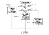
そして、ステップS360またはステップS361の処理を終えると、つまり今回取得した大当り図柄が特定大当図柄または通常大当図柄であった場合には、CPU102は、ステップS600へ移行して大当り演出画像選択処理を実行する。図26は、大当り演出画像選択処理(ステップS600)を示すフローチャートである。CPU102は、この大当り演出画像選択処理が実行されると、まずステップS602の処理にて、カウンタHの値が10未満か否かを判定する。そして、ステップS602の処理にてYES、即ちカウンタHの値が10未満(0〜9)であった場合には、ステップS604の処理へ移行し
て、CPU102は、今回の大当り遊技に係わる大当り演出画像として大当り演出画像Aを選択し、この大当り演出画像Aを画像表示装置80の画像表示部81に優先的に表示指示するための大当り演出画像指定コマンド信号を表示制御回路111に出力する。なお、この大当り演出画像指定コマンドについては、図33に示し後述する。
When the process of step S360 or step S361 is completed, that is, when the big hit symbol acquired this time is a specific big hit symbol or a normal big hit symbol, the CPU 102 proceeds to step S600 and performs a big hit effect image selection process. Execute. FIG. 26 is a flowchart showing the big hit effect image selection process (step S600). When the big hit effect image selection process is executed, the CPU 102 first determines whether or not the value of the counter H is less than 10 in the process of step S602. If YES in the process of step S602, that is, if the value of the counter H is less than 10 (0 to 9), the process proceeds to step S604, and the CPU 102 performs the jackpot effect related to the current jackpot game. The jackpot effect image A is selected as an image, and a jackpot effect image designation command signal for preferentially displaying the jackpot effect image A on the image display unit 81 of the image display device 80 is output to the display control circuit 111. The jackpot effect image designation command is shown in FIG. 33 and will be described later.

一方、ステップS602の処理にてNO、即ちカウンタHの値が10以上であった場合には、ステップS606の処理へ移行して、CPU102は、カウンタHの値が10以上20未満か否かを判定する。そして、ステップS606の処理にてYES、即ちカウンタHの値が10以上20未満(10〜19)であった場合には、ステップS608の処理へ移行して、CPU102は、今回の大当り遊技に係わる大当り演出画像として大当り演出画像Bを選択し、この大当り演出画像Bを画像表示装置80の画像表示部81に優先的に表示指示するための大当り演出画像指定コマンド信号を表示制御回路111に出力する。   On the other hand, if NO in step S602, that is, if the value of the counter H is 10 or more, the process proceeds to step S606, and the CPU 102 determines whether the value of the counter H is 10 or more and less than 20. judge. If YES in step S606, that is, if the value of the counter H is not less than 10 and less than 20 (10 to 19), the process proceeds to step S608, and the CPU 102 relates to the current big hit game. A jackpot effect image B is selected as the jackpot effect image, and a jackpot effect image designation command signal for preferentially displaying the jackpot effect image B on the image display unit 81 of the image display device 80 is output to the display control circuit 111. .

一方、ステップS606の処理にてNO、即ちカウンタHの値が20以上であった場合には、ステップS610の処理へ移行して、CPU102は、今回の大当り遊技に係わる大当り演出画像として大当り演出画像Cを選択し、この大当り演出画像Cを画像表示装置80の画像表示部81に優先的に表示指示するための大当り演出画像指定コマンド信号を表示制御回路111に出力する。   On the other hand, if NO in step S606, that is, if the value of the counter H is 20 or more, the process proceeds to step S610, and the CPU 102 receives a big hit effect image as a big hit effect image related to the current big hit game. C is selected, and a jackpot effect image designation command signal for instructing to preferentially display the jackpot effect image C on the image display unit 81 of the image display device 80 is output to the display control circuit 111.

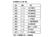
ここで、図27を参照して大当り演出画像について説明する。図27は、大当り演出画像とカウンタHとの関係を示す説明図である。図27に示すように大当り演出画像は、それぞれ演出効果の異なる3種類の大当り演出画像A、B、Cが用意されており、大当り演出画像Aの演出効果は最も低く、大当り演出画像Cの演出効果は最も高く、大当り演出画像Bの演出効果は、大当り演出画像Aと大当り演出画像Cの演出効果の中位になっている。つまり大当り演出画像は、上記した大当り演出画像選択処理(ステップS600)に示したように、カウンタHの値が低いと、即ちオーバーフロー球数が少ないと演出効果の低くい大当り演出画像が画像表示装置80に表示され、カウンタHの値が高くなるにつれて演出効果の高い大当り演出画像が画像表示装置80に表示されるようになっている。   Here, the big hit effect image will be described with reference to FIG. FIG. 27 is an explanatory diagram showing the relationship between the big hit effect image and the counter H. As shown in FIG. 27, the jackpot effect image has three types of jackpot effect images A, B, and C, each having a different effect, and the effect of the jackpot effect image A is the lowest. The effect is the highest, and the effect of the jackpot effect image B is the middle of the effect of the jackpot effect image A and the jackpot effect image C. In other words, as shown in the above-described jackpot effect image selection process (step S600), the jackpot effect image has a low effect if the value of the counter H is low, that is, the number of overflow balls is small. A big hit effect image with a high effect is displayed on the image display device 80 as the value of the counter H increases.

図26に戻り、ステップS604、ステップS608またはステップS610の処理を終えると、CPU102は、この大当り演出画像選択処理(ステップS600)を終了し、ステップS367に移行する。   Returning to FIG. 26, when the process of step S604, step S608, or step S610 is completed, the CPU 102 ends the jackpot effect image selection process (step S600), and proceeds to step S367.

図25に戻ってステップS600またはS365の処理を終えると、CPU102は、ステップS367へ移行してLED・ランプ点灯制御処理を実行し、ここでCPU102は、上記したランプ制御回路37を駆動して遊技盤面に配備されているLEDやランプ等を所定の態様で点灯したり点滅したりする制御を実行する。この処理により、特別図柄表示装置6に大当りやリーチに係わる変動パターンが表示されたことを遊技者に報知できると共に、遊技の演出度を向上させることができる。   Returning to FIG. 25, when the processing of step S600 or S365 is completed, the CPU 102 proceeds to step S367 to execute the LED / lamp lighting control processing. Here, the CPU 102 drives the lamp control circuit 37 and plays Control is performed to turn on or blink LEDs or lamps provided on the board in a predetermined manner. By this processing, it is possible to notify the player that the special symbol display device 6 has displayed the variation pattern related to the big hit or the reach, and it is possible to improve the performance level of the game.

そして、ステップS367のLED・ランプ点灯制御処理またはステップS363の変動パターン1の表示を指示する処理を終えると、CPU102は、ステップS357の効果音出力処理へ移行し、ここで、この特別図柄変動表示処理(ステップS356)にて変動表示されている変動パターンに対応する効果音を、音声制御回路38を介してスピーカ113より出力すると共に、画像表示制御回路112に出力する。   When the LED / lamp lighting control process in step S367 or the process for instructing the display of the fluctuation pattern 1 in step S363 is finished, the CPU 102 proceeds to the sound effect output process in step S357, where the special symbol fluctuation display is performed. The sound effect corresponding to the variation pattern variably displayed in the process (step S356) is output from the speaker 113 via the audio control circuit 38 and also output to the image display control circuit 112.

そして、ステップS357の効果音出力処理を終えると、CPU102は、ステップS368の処理へ移行し、ここで左特別図柄の停止図柄を指定するための左特別図柄指定コマンド信号を表示制御回路111に出力し、ステップS369の処理へ移行し、ここで右特別図柄の停止図柄を指定するための右特別図柄指定コマンド信号を表示制御回路111
に出力し、ステップS370の処理へ移行し、ここで中特別図柄の停止図柄を指定するための中特別図柄指定コマンド信号を表示制御回路111に出力する。なお、これらの左特別図柄指定コマンド、右特別図柄指定コマンド、中特別図柄指定コマンドについては、図33に示し後述する。
When the sound effect output process in step S357 is completed, the CPU 102 proceeds to the process in step S368, and outputs a left special symbol designation command signal for designating a stop symbol of the left special symbol to the display control circuit 111. Then, the process proceeds to step S369, where a right special symbol designation command signal for designating a stop symbol of the right special symbol is displayed on the display control circuit 111.
Then, the process proceeds to step S370, where a medium special symbol designation command signal for designating a stop symbol of the middle special symbol is outputted to the display control circuit 111. Note that these left special symbol designation command, right special symbol designation command, and middle special symbol designation command are shown in FIG. 33 and will be described later.

また、ステップS368、ステップS369及びステップS370の処理にて指定される特別図柄は、それぞれ上記したステップS349、ステップS351、ステップS352またはステップS353の処理にて図柄格納バッファから取得した図柄データに対応したものとなっている(図21参照)。ステップS370の処理を終えると、CPU102は、この特別図柄変動表示処理(ステップS356)を終了して特別図柄制御処理(図24)に戻り、ステップS371の処理へ移行する。   In addition, the special symbols specified in the processing of step S368, step S369, and step S370 correspond to the symbol data acquired from the symbol storage buffer in the processing of step S349, step S351, step S352, or step S353 described above, respectively. (See FIG. 21). When the process of step S370 is completed, the CPU 102 ends the special symbol variation display process (step S356), returns to the special symbol control process (FIG. 24), and proceeds to the process of step S371.

ステップS371の処理へ移行すると、CPU102は、予め設定されている特別図柄変動時間THがタイムアップ(TH=0)したか否かを判定する。なお、この特別図柄変動時間THについては後述する。そして、ステップS371の処理にてNO、即ち特別図柄変動時間THがタイムアップしていないと判定された場合には、CPU102は、この特別図柄制御処理(ステップS354)を終了して特別図柄遊技処理に戻り、ステップS376の処理へ移行する。一方、ステップS371の処理にてYES、即ち特別図柄変動時間THがタイムアップしたと判定された場合には、ステップS372の処理へ移行し、CPU102は、ここで全ての特別図柄の停止を指定するための全図柄停止指定コマンド信号を表示制御回路111に出力する。なお、この全図柄停止指定コマンドについては、図33に示し後述する。ステップS372の処理を終えると、CPU102は、ステップS373の特別図柄確定の処理へ移行する。   When the process proceeds to step S371, the CPU 102 determines whether or not the special symbol variation time TH set in advance is up (TH = 0). The special symbol variation time TH will be described later. If NO in step S371, that is, if it is determined that the special symbol variation time TH has not increased, the CPU 102 ends the special symbol control process (step S354) and performs the special symbol game process. Returning to step S376, the process proceeds to step S376. On the other hand, if YES in the process of step S371, that is, if it is determined that the special symbol variation time TH has timed up, the process proceeds to step S372, and the CPU 102 designates stop of all special symbols here. All symbol stop designation command signals are output to the display control circuit 111. This all symbol stop designation command is shown in FIG. 33 and will be described later. When the process of step S372 is completed, the CPU 102 proceeds to the special symbol determination process of step S373.

ステップS373の処理へ移行すると、CPU102は、上記したようにステップS346の特別図柄決定処理にて決定された特別図柄を特別図柄表示装置6に確定する処理を実行する。このステップS373の処理における特別図柄の確定は、上記全図柄停止指定コマンドに基づいて特別図柄表示装置6上で停止した特別図柄を、所定時間(2秒)停止したままの状態を維持することで行う。   When the process proceeds to the process of step S373, the CPU 102 executes a process of determining the special symbol determined in the special symbol determination process of step S346 in the special symbol display device 6 as described above. The determination of the special symbol in the process of step S373 is performed by maintaining the state where the special symbol stopped on the special symbol display device 6 is stopped for a predetermined time (2 seconds) based on the all symbol stop designation command. Do.

なお、特別図柄の確定とは、特別図柄(左特別図柄、中特別図柄、右特別図柄)が完全に停止している状態が所定時間(2秒)継続されるものを言い、各図柄表示部8、9、10上で、例えば上下に数コマ程度微動している揺れ状態を含むものではなく、一方、特別図柄の停止とは、この揺れ状態を含むものであり、つまり特別図柄の停止とは、特別図柄が完全に停止している状態でなくとも、遊技者がそれを認識できる程度であれば、どのような態様であっても良い。   The confirmation of the special symbol means that the special symbol (left special symbol, middle special symbol, right special symbol) is completely stopped for a predetermined time (2 seconds). On the other hand, it does not include a shaking state that is slightly moved up and down, for example, several frames up and down, while the special symbol stop includes this shaking state, that is, the special symbol stop and May be in any form as long as the player can recognize it even if the special symbol is not completely stopped.

ステップS373の処理を終えると、CPU102は、ステップS374の処理へ移行して、リーチフラグF2の値を0にセットし、ステップS375の処理へ移行して、リーチ態様フラグF3の値を0にセットする。なお、上記ステップS348、ステップS362の処理にてYESと判定されていたとき及び上記ステップS350、ステップS364の処理にてYESと判定されていたときは、CPU102は、ステップS374及びステップS375の処理では、なにも実行しない。ステップS375の処理を終えると、CPU102は、この特別図柄制御処理(ステップS354)を終了して特別図柄遊技処理(図20)に戻り、ステップS376の処理へ移行する。   When the process of step S373 is completed, the CPU 102 proceeds to the process of step S374, sets the value of the reach flag F2 to 0, shifts to the process of step S375, and sets the value of the reach mode flag F3 to 0. To do. When it is determined YES in the processes of steps S348 and S362 and when YES is determined in the processes of steps S350 and S364, the CPU 102 performs the processes in steps S374 and S375. , Do nothing. When the process of step S375 is completed, the CPU 102 ends the special symbol control process (step S354), returns to the special symbol game process (FIG. 20), and proceeds to the process of step S376.

ステップS376の処理へ移行すると、CPU102は、ここで特別図柄表示装置6に表示される特別図柄が確定したか否かを判定し、確定していない場合(ステップS376にてNO)には、この特別図柄遊技処理(ステップS318)を終了して特別遊技処理(図17)に戻り、メイン遊技処理(図7)のステップS50の処理へ移行する。一方、ス
テップS376の処理にて、特別図柄表示装置6に表示される特別図柄が確定したと判定された場合(ステップS376にてYES)には、ステップS380の処理へ移行する。
When the process proceeds to step S376, the CPU 102 determines whether or not the special symbol displayed on the special symbol display device 6 has been confirmed. If not (NO in step S376), the CPU 102 determines this. The special symbol game process (step S318) is terminated, the process returns to the special game process (FIG. 17), and the process proceeds to step S50 of the main game process (FIG. 7). On the other hand, when it is determined in step S376 that the special symbol displayed on special symbol display device 6 has been determined (YES in step S376), the process proceeds to step S380.

ステップS380へ移行すると、CPU102は、ここで大当りフラグF1の値が1か否かを判定し、大当りフラグF1の値が1の場合(ステップS380にてYES)には、ステップS381へ移行して、時短処理解除の処理実行する。   When the process proceeds to step S380, CPU 102 determines whether or not the value of jackpot flag F1 is 1, and if the value of jackpot flag F1 is 1 (YES in step S380), the process proceeds to step S381. Then, the processing for canceling the short time processing is executed.

なお、このステップS381の時短処理解除の処理とは、後述するステップS412の時短処理にて設定される処理を解除して通常時の設定に戻す処理であって、ここでの詳しい説明は省略するが、簡略に言うと、上記した当り判定用カウンタC9(乱数9、0〜30)、普通図柄変動時間t、始動入賞口開放時間ST、大当り判定用カウンタC1(乱数1、0〜314)及び特別図柄変動時間THの各内容を通常時の設定に戻す処理である。従って、後述するステップS412の時短処理が実行されていないときは、CPU102は、ここでは何も処理しない。   Note that the processing for canceling the time-saving process in step S381 is processing for canceling the processing set in the time-saving processing in step S412 to be described later and returning it to the normal setting, and detailed description thereof is omitted here. In short, the hit determination counter C9 (random numbers 9, 0 to 30), the normal symbol variation time t, the start winning opening opening time ST, the big hit determination counter C1 (random numbers 1, 0 to 314), and This is processing for returning each content of the special symbol variation time TH to the normal setting. Therefore, when the time reduction process in step S412 described later is not executed, the CPU 102 does not perform any process here.

ステップS381の時短処理解除の処理を終えると、CPU102は、ステップS383の処理へ移行し、ここで大当り遊技開始指定コマンド信号を表示制御回路111に出力し、ステップS391へ移行して、図28に示す大当り処理を実行する。なお、この大当り遊技開始指定コマンドについては、図33に示し後述する。   When the processing for canceling the time-saving process in step S381 is completed, the CPU 102 proceeds to the process in step S383, where the jackpot game start designation command signal is output to the display control circuit 111, and the process proceeds to step S391. The indicated jackpot process is executed. The jackpot game start designation command is shown in FIG. 33 and will be described later.

図28は、大当り処理(ステップS391)を示すフローチャートである。CPU102は、この大当り処理(ステップS391)が実行されると、まずステップS392の処理にて、インターバルタイム中か否かを判定する。このインターバルタイムとは、大当り遊技中において、大当り遊技開始時、各ラウンド終了時、大当り遊技終了時に設けられる大入賞口(アタッカ)7が閉口している時間のことで、インターバルタイム中と判定された場合(ステップS392にてYES)には、この大当り処理(ステップS391)を終了して特別図柄遊技処理(図20)に戻り、ステップS409の処理へ移行する。なお、大当り遊技開始時及び大当り遊技終了時のインターバルタイムは10秒、各ラウンド終了時のインターバルタイムは2秒に設定されている。   FIG. 28 is a flowchart showing the big hit process (step S391). When the jackpot process (step S391) is executed, the CPU 102 first determines whether or not the interval time is in the process of step S392. This interval time is the time during which the big winning game (attacker) 7 is closed at the start of the big hit game, at the end of each round, or at the end of the big hit game. If YES (YES in step S392), the jackpot process (step S391) is terminated, the process returns to the special symbol game process (FIG. 20), and the process proceeds to step S409. The interval time at the start of the big hit game and the end of the big hit game is set to 10 seconds, and the interval time at the end of each round is set to 2 seconds.

一方、ステップS392の処理にて、インターバルタイム中でないと判定された場合(ステップS392にてNO)には、ステップS393の処理へ移行し、CPU102は、ここで後述するカウンタEの値に基づいてラウンド表示指定コマンド信号を表示制御回路111に出力する。なお、このラウンド表示指定コマンドについては、図33に示し後述する。   On the other hand, when it is determined in step S392 that the interval time is not reached (NO in step S392), the process proceeds to step S393, and the CPU 102 determines the value of counter E, which will be described later. A round display designation command signal is output to the display control circuit 111. The round display designation command is shown in FIG. 33 and will be described later.

次に、ステップS394の処理へ移行すると、CPU102は、ソレノイド106を駆動制御して大入賞口7を開口する。そして、ステップS395の処理へ移行して、CPU102は、予め設定されている所定の大入賞口7の開口時間30秒がタイムアップしたか否かを判定し、ステップS395の処理にてNO、即ち大入賞口7の開口時間30秒がタイムアップしていないと判定された場合には、ステップS396の処理へ移行して、ラウンド中に大入賞口7内に入賞した遊技球数を表示するためのカウント表示指定コマンド信号を、カウンタDに同期させて表示制御回路111に出力する。このカウンタDは、開口された大入賞口7が上記大入賞口開口時間30秒が経過して閉口するまでに、大入賞口7内入賞した遊技球の数をカウントするために主制御回路44に設定されたカウンタであり、カウントスイッチ117が遊技球を検出したときにカウントアップされ、電源投入時には初期化されて0がセットされるようになっている。なお、カウント表示指定コマンドについては、図33に示し後述する。   Next, when the process proceeds to step S394, the CPU 102 drives and controls the solenoid 106 to open the special winning opening 7. Then, the process proceeds to the process of step S395, and the CPU 102 determines whether or not the predetermined opening time 30 of the predetermined prize winning opening 7 has expired, and NO in the process of step S395, that is, When it is determined that the opening time 30 seconds of the big winning opening 7 has not timed up, the process proceeds to step S396 to display the number of game balls won in the big winning opening 7 during the round. Are output to the display control circuit 111 in synchronization with the counter D. The counter D is a main control circuit 44 for counting the number of game balls won in the big prize opening 7 until the opened big prize opening 7 is closed after the opening time of the big prize opening 30 seconds elapses. Is counted up when the count switch 117 detects a game ball, and is initialized and set to 0 when the power is turned on. The count display designation command is shown in FIG. 33 and will be described later.

次に、ステップS397の処理へ移行すると、CPU102は、上記した継続入賞スイ
ッチ118がオンしたか否か、即ちラウンド中に継続入賞スイッチ118が大入賞口7の特定領域を通過した遊技球を検出したか否かを判定し、遊技球が大入賞口7の特定領域を通過して継続入賞スイッチ118がオンしている場合(後述するステップS404にてYES)には、CPU102は、ステップS398の処理へ移行して、Vを表示するためのV表示指定コマンド信号を、継続入賞スイッチ118の検出信号に同期して表示制御回路111に出力し、ステップS399の処理へ移行する。なお、このV表示指定コマンドについては、図33に示し後述する。
Next, when proceeding to the processing of step S397, the CPU 102 detects whether or not the above-described continuous winning switch 118 is turned on, that is, a game ball in which the continuous winning switch 118 has passed a specific area of the big winning opening 7 during the round. If the game ball passes through a specific area of the big winning opening 7 and the continuous winning switch 118 is turned on (YES in step S404 described later), the CPU 102 proceeds to step S398. The process proceeds to processing, and a V display designation command signal for displaying V is output to the display control circuit 111 in synchronization with the detection signal of the continuous winning switch 118, and the process proceeds to step S399. The V display designation command is shown in FIG. 33 and will be described later.

一方、ステップS397の処理にてNOと判定された場合、即ちラウンド中に継続入賞スイッチ118がオンしておらず遊技球が大入賞口7の特定領域を通過していない場合には、CPU102は、ステップS399の処理へ移行して、カウンタDの値が10以上か否かを判定する。そして、ステップS399の処理にてNO、即ちカウンタDの値が10未満と判定されたときには、CPU102は、この大当り処理を終了してステップS409の処理に移行する。   On the other hand, when it is determined NO in the process of step S397, that is, when the continuous winning switch 118 is not turned on during the round and the game ball has not passed the specific area of the big winning opening 7, the CPU 102 Then, the process proceeds to step S399, and it is determined whether or not the value of the counter D is 10 or more. If NO in step S399, that is, if the value of the counter D is determined to be less than 10, the CPU 102 ends the jackpot process and proceeds to the process in step S409.

一方、ステップS395の処理にてYES及びステップS399の処理にてYESと判定された場合、即ち大入賞口7の開口時間30秒がタイムアップしたと判定された場合及びカウンタDの値が10以上と判定された場合には、ステップS400の処理へ移行して、CPU102は、ソレノイド106を駆動制御して大入賞口7を閉口する。そして、CPU102は、ステップS401の処理へ移行して、カウンタDの値を0にセットし、ステップS402の処理へ移行して、カウンタEの値をインクリメント(1加算)する。   On the other hand, if YES is determined in the process of step S395 and YES is determined in the process of step S399, that is, if it is determined that the opening time 30 seconds of the big winning opening 7 is up, and the value of the counter D is 10 or more. When it is determined that the process proceeds to step S400, the CPU 102 drives and controls the solenoid 106 to close the special winning opening 7. Then, the CPU 102 proceeds to the process of step S401, sets the value of the counter D to 0, proceeds to the process of step S402, and increments (adds 1) the value of the counter E.

このカウンタEは、大入賞口7が何回開口されたかを、換言すれば上記した大当り遊技中の各ラウンドが何回実行されたかをカウントするために主制御回路44に設定されたカウンタであり、ステップS400の処理が実行されて大入賞口7が閉口する毎にカウントアップされ、電源投入時には初期化されて1がセットされるようになっている。   This counter E is a counter set in the main control circuit 44 in order to count how many times the big winning opening 7 is opened, in other words, how many times each round in the big hit game is executed. Every time the process of step S400 is executed and the special winning opening 7 is closed, it is counted up, and is initialized and set to 1 when the power is turned on.

ステップS402の処理を終えると、ステップS404の処理へ移行して、CPU102は、上記ステップS397の処理にて継続入賞スイッチ118がオンしたか否かを判定し、継続入賞スイッチ118がオンしていた場合(ステップS404にてYES)には、ステップS405の処理へ移行して、カウンタEの値が16未満か否かを判定する。このステップS405の処理では、大入賞口7が開口される回数、即ち大当り遊技中のラウンド数が16回になったか否かを判定している。そして、ステップS405の処理にてYES、即ちカウンタEの値が16以下と判定されたときには、CPU102は、この大当り処理を終了してステップS409の処理(図20)に移行する。   When the process of step S402 is completed, the process proceeds to the process of step S404, and the CPU 102 determines whether or not the continuous winning switch 118 is turned on in the process of step S397, and the continuous winning switch 118 is turned on. If YES (YES in step S404), the process proceeds to step S405 to determine whether the value of the counter E is less than 16. In the process of step S405, it is determined whether or not the number of times that the big winning opening 7 is opened, that is, whether or not the number of rounds in the big hit game has become 16 times. When YES is determined in the process of step S405, that is, when the value of the counter E is determined to be 16 or less, the CPU 102 ends the jackpot process and proceeds to the process of step S409 (FIG. 20).

一方、ステップS404の処理にてNO及びステップS405の処理にてNOと判定された場合、即ち継続入賞スイッチ118がオンしておらず遊技球が大入賞口7の特定領域を通過していない場合及びカウンタEの値が16を超えていると判定された場合には、CPU102は、ステップS406の処理へ移行して、カウンタEの値を0にセットし、ステップS407の処理へ移行して、大当りフラグF1の値を0にセットし、ステップS408の処理へ移行して、カウンタHの値を0にセットし、この大当り処理を終了してステップS409の処理(図20)に移行する。なお、ステップS408の処理にてカウンタHの値が0にセットされると、オーバーフロー球表示装置60に表示されるオーバーフロー球数の値もリセットされて0となる。   On the other hand, when it is determined NO in the process of step S404 and NO in the process of step S405, that is, when the continuous winning switch 118 is not turned on and the game ball has not passed the specific area of the big winning opening 7. When it is determined that the value of the counter E exceeds 16, the CPU 102 proceeds to the process of step S406, sets the value of the counter E to 0, and proceeds to the process of step S407. The value of the big hit flag F1 is set to 0, the process proceeds to step S408, the value of the counter H is set to 0, the big hit process is terminated, and the process proceeds to the process of step S409 (FIG. 20). When the value of the counter H is set to 0 in the process of step S408, the value of the overflow ball number displayed on the overflow ball display device 60 is also reset to 0.

ステップS409の処理に移行すると、CPU102は、大当りフラグF1の値が0か否か、即ち所定の大当り処理(ステップS391)が全て終了したか否かを判定し、大当りフラグF1の値が0でない場合(ステップS409の処理にてNO)、即ち大当りフラグF1の値が1の場合には、所定の大当り処理が全て終了していないと判定し、この特別
図柄遊技処理(ステップS318)を終了して特別遊技処理(図17)に戻り、メイン遊技処理(図7)のステップS50の処理へ移行する。一方、大当りフラグF1の値が0の場合(ステップS409にてYES)には、ステップS410の処理へ移行して、CPU102は、ここで大当り遊技終了指定コマンド信号を表示制御回路111に出力する。なお、この大当り遊技終了指定コマンドについては、図33に示し後述する。
When the processing proceeds to step S409, the CPU 102 determines whether or not the value of the big hit flag F1 is 0, that is, whether or not all of the predetermined big hit processing (step S391) is completed, and the value of the big hit flag F1 is not 0. If this is the case (NO in step S409), that is, if the value of the jackpot flag F1 is 1, it is determined that all of the predetermined jackpot processing has not ended, and this special symbol game processing (step S318) is terminated. Then, the process returns to the special game process (FIG. 17) and proceeds to the process of step S50 of the main game process (FIG. 7). On the other hand, if the value of big hit flag F1 is 0 (YES in step S409), the process proceeds to step S410, and CPU 102 here outputs a big hit game end designation command signal to display control circuit 111. The jackpot game end designation command is shown in FIG. 33 and will be described later.

次に、ステップS411の処理へ移行して、CPU102は、上記したステップS359の処理(図25)と同様、大当り図柄が奇数のゾロ目の数字図柄か否かを、即ち特定大当図柄か否かを判定する。そして、ステップS411の処理にてYES、即ち今回取得した大当り図柄が特定大当図柄であった場合には、ステップS412の処理へ移行して、CPU102は、時短処理を実行する。   Next, the process proceeds to the process of step S411, and the CPU 102 determines whether or not the jackpot symbol is an odd numbered number symbol, that is, whether it is a specific big win symbol, as in the process of step S359 described above (FIG. 25). Determine whether. If YES in the process of step S411, that is, if the jackpot symbol acquired this time is a specific bonus symbol, the process proceeds to step S412 and the CPU 102 executes a time reduction process.

図29は、時短処理(ステップS412)を示すフローチャートである。この時短処理が開始されるとCPU102は、まずステップS414の処理にて上記したステップS20の乱数更新処理にて更新する当り判定用カウンタC9(乱数9、0〜30)の内容を変更する。通常時、ステップS20の処理において作成される乱数9は、普通図柄が当りとなる抽選確率は10/31であるが、時短処理が実行されたことによって、この当りとなる抽選確率を28/31に上昇させる。これは、上記した0〜30で構成された乱数のうち0〜9を当り乱数としていたのを、0〜27を当り乱数に変更することで行う。   FIG. 29 is a flowchart showing the time reduction process (step S412). When the time reduction process is started, the CPU 102 first changes the contents of the hit determination counter C9 (random numbers 9, 0 to 30) updated in the random number update process in step S20 described above in the process in step S414. Normally, the random number 9 generated in the process of step S20 has a lottery probability that a normal symbol is a hit, but is 10/31. To rise. This is done by changing 0 to 27 to random numbers instead of 0 to 9 among the random numbers composed of 0 to 30 described above.

次に、ステップS416の処理へ移行して、CPU102は、上記した普通図柄制御処理(図14)のステップS508にて用いる普通図柄変動時間tを短縮する。通常時、普通図柄変動時間tは30秒であるが、時短処理が実行されたことによって、この普通図柄変動時間tを2秒に短縮する。即ち、上記した普通図柄制御処理(ステップS504)のステップS506で変動表示が開始され、ステップS510にて当り図柄またははずれ図柄が確定表示されるまでの普通図柄の変動表示時間が30秒であったのを、2秒に短縮する。   Next, the process proceeds to step S416, and the CPU 102 shortens the normal symbol variation time t used in step S508 of the above-described normal symbol control process (FIG. 14). Normally, the normal symbol variation time t is 30 seconds, but the normal symbol variation time t is shortened to 2 seconds by executing the time reduction process. That is, the variable display is started in step S506 of the above normal symbol control process (step S504), and the normal symbol change display time is 30 seconds until the winning symbol or the off symbol is fixedly displayed in step S510. Is reduced to 2 seconds.

次に、ステップS418の処理へ移行して、CPU102は、上記した始動入賞口開放処理(図15)のステップS520にて用いる始動入賞口開放時間STを延長する。通常時、始動入賞口開放時間STは0.2秒であるが、時短処理が実行されたことによって、この始動入賞口開放時間STを2秒に延長する。即ち、上記した始動入賞口開放処理(ステップS516)のステップS518で開放され、ステップS524にて閉口されるまでの始動入賞口(電動チューリップ)11の開放時間が0.2秒であったのを、2秒に延長する。   Next, the process proceeds to step S418, and the CPU 102 extends the start winning opening opening time ST used in step S520 of the above starting winning opening opening process (FIG. 15). Normally, the start winning opening opening time ST is 0.2 seconds. However, the start winning opening opening time ST is extended to 2 seconds by the execution of the time reduction process. That is, the opening time of the start winning port (electric tulip) 11 until the opening is closed in step S518 of the start winning port opening process (step S516) and closed in step S524 is 0.2 seconds. Extend to 2 seconds.

次に、ステップS420へ移行して、CPU102は、上記したステップS20の乱数更新処理にて更新する大当り判定用カウンタC1(乱数1、0〜314)の内容を変更する。通常時、ステップS20の処理において作成される乱数1は、特別図柄の組合せが大当りとなる抽選確率は1/315であるが、時短処理が実行されたことによって、この大当りとなる抽選確率を5/315に上昇させる。これは、上記した0〜350で構成された大当り乱数のうち7のみ大当り乱数としていたのを、7、33、77、111、222、を大当り乱数に変更することで行う。   Next, proceeding to step S420, the CPU 102 changes the contents of the jackpot determination counter C1 (random numbers 1, 0 to 314) updated by the random number update process of step S20 described above. Normally, the random number 1 created in the process of step S20 has a lottery probability that the special symbol combination is a big win, but it is 1/315. To 315. This is performed by changing 7, 33, 77, 111, and 222 to the big hit random numbers instead of the big hit random numbers consisting of 0 to 350 described above as the big hit random numbers.

次に、ステップS422へ移行して、CPU102は、上記した特別図柄制御処理(図24)のステップS371にて用いる特別図柄変動時間THを短縮する。通常時、特別図柄変動時間THは7〜42秒(大当りやリーチになる場合は13〜42秒、それ以外は7秒)であるが、時短処理が実行されたことによって、この特別図柄変動時間THを2〜37秒(大当りやリーチになる場合は8〜37秒、それ以外は2秒)に短縮する。即ち、上記した特別図柄制御処理(ステップS354)のステップS356で変動表示が開始され
、ステップS373にて大当り図柄またははずれ図柄が確定されるまでの特別図柄の変動表示時間が7〜42秒であったのを、2〜37秒に短縮する。そしてステップS422の処理を終えると、この時短処理(ステップS412)を終了して特別図柄遊技処理(図20)のステップS431の処理へ移行する。
Next, proceeding to step S422, the CPU 102 shortens the special symbol variation time TH used in step S371 of the special symbol control process (FIG. 24) described above. Normally, the special symbol variation time TH is 7 to 42 seconds (13 to 42 seconds in the case of big hit or reach, and 7 seconds otherwise). TH is shortened to 2 to 37 seconds (8 to 37 seconds for a big hit or reach, otherwise 2 seconds). That is, the variable display is started in step S356 of the special symbol control process (step S354) described above, and the special symbol variation display time until the big hit symbol or the off symbol is determined in step S373 is 7 to 42 seconds. Is reduced to 2 to 37 seconds. When the process of step S422 is completed, the time saving process (step S412) is terminated, and the process proceeds to the process of step S431 of the special symbol game process (FIG. 20).

一方、ステップS411の処理にてNO、即ち今回取得した大当り図柄が特定大当図柄でない場合(上記した偶数のゾロ目の数字図柄としての通常大当図柄であった場合)には、ステップS431の処理へ移行して、CPU102は、画像表示装置80に表示されている大当り演出画像A、B、Cが終了したか否かを判定する。この大当り演出画像A、B、Cは、詳しい説明は後述するが、ステップS391の大当り処理が開始(ステップS383の大当り遊技開始指定コマンド信号が出力)されてから約532秒間表示されるようになっており、この532秒は、大当り遊技における各ラウンド時間が最長の30秒間継続した場合の大当り遊技時間にほぼ等しい時間となっている(大当り遊技開始時インターバルタイム+ラウンド時間×16+ラウンド間インターバルタイム×16+大当り遊技終了時インターバルタイム=10秒+30秒×16+2秒×16+10秒=532秒)。つまり、この532秒間というのは、遊技者が大当り遊技を実行しているにもかかわらず大当り演出画像A、B、Cが終了してしまうのを避けるためのものであり、従って、ほとんどの遊技者は、大当り遊技を終了した後でも、画像表示装置80には、まだ大当り演出画像A、B、Cが表示されることになる。   On the other hand, if NO in the process of step S411, that is, if the jackpot symbol acquired this time is not a specific bonus symbol (when it is a normal bonus symbol as the above-mentioned even-numbered symbol symbol), step S431 is performed. Shifting to processing, the CPU 102 determines whether or not the big hit effect images A, B, and C displayed on the image display device 80 have ended. The jackpot effect images A, B, and C will be displayed for about 532 seconds after the jackpot processing in step S391 is started (the jackpot game start designation command signal is output in step S383). This 532 seconds is approximately equal to the jackpot game time when each round time in the jackpot game continues for the longest 30 seconds (interval time at the start of jackpot game + round time × 16 + interval time between rounds) × 16 + Large hit game end time = 10 seconds + 30 seconds × 16 + 2 seconds × 16 + 10 seconds = 532 seconds). In other words, this 532 seconds is for avoiding that the big hit effect images A, B, and C end even though the player is executing the big hit game. Even after the player has finished the big hit game, the big hit effect images A, B, and C are still displayed on the image display device 80.

即ち、大当り演出画像A、B、Cは、大当り遊技の終了には関係なく、最後まで完結して表示されるようになっている。そしてステップS431の処理にてYES、つまり大当り演出画像A、B、Cの表示が終了した場合には、ステップS432の処理へ移行して、CPU102は、ここで大当り演出画像終了指定コマンド信号を表示制御回路111に出力し、ステップS434の処理へ移行する。なお、この大当り演出画像終了指定コマンドについては、図33に示し後述する。一方、ステップS431の処理にてNO、つまり大当り演出画像A、B、Cの表示が終了していない場合には、CPU102は、直接ステップS434の処理へ移行する。   That is, the jackpot effect images A, B, and C are displayed completely until the end regardless of the end of the jackpot game. If YES in the process of step S431, that is, if the display of the big hit effect image A, B, C is completed, the process proceeds to step S432, and the CPU 102 displays a big hit effect image end designation command signal here. The data is output to the control circuit 111, and the process proceeds to step S434. The jackpot effect image end designation command is shown in FIG. 33 and will be described later. On the other hand, if NO in the process of step S431, that is, if the display of the big hit effect images A, B, and C has not ended, the CPU 102 proceeds directly to the process of step S434.

ステップS434の処理へ移行すると、CPU102は、上記したステップS306の処理(図18)にてインクリメント(1加算)されたカウンタBの値をディクリメント(1減算)し、ステップS436の処理へ移行して保留LED消灯制御処理を実行する。   After shifting to the process of step S434, the CPU 102 decrements (decrements 1) the value of the counter B incremented (added by 1) in the process of step S306 (FIG. 18) described above, and shifts to the process of step S436. The hold LED extinguishing control process is executed.

なお、上記したように、ステップS411にてNO、即ち取得した大当り図柄が奇数の大当り図柄(特定大当図柄)でなかった場合には、本実施例においてはステップS412の時短処理は実行されないようにしたが、例えばこの場合にも回数限定の時短処理を行うようにしても良い。具体的には、大当り図柄が特定大当図柄であった場合には(ステップS411にてYES)、本実施例では次の大当りがくるまで時短処理が実行され、一方偶数の大当り図柄(通常大当図柄)であったときには(ステップS411にてNO)、ステップS381にて解除された時短処理は維持されるようになっているが、これに変えて、偶数の大当り図柄(通常大当図柄)であった場合にも、例えば最高100回の特別図柄遊技処理(ステップS318)が実行される間、換言すれば特別図柄の変動表示回数が100回実行される間、時短処理が設定されるようにしても良い。さらにこれは、時短処理が設定されている間に、偶数の大当り図柄(通常大当図柄)にて大当りになったときのみに採用するようにしても良い。このようにすることで、通常大当図柄をひいた場合であっても、遊技者にとって極めて有利となる時短処理が所定回数実行されるようになるので、適度な射幸性を遊技者に与えることが可能となり、遊技性が著しく向上する。なお、このような回数限定の時短処理においては、上記したステップS420の大当り確率を上昇させる処理は実行しないようにしても良い。   As described above, if NO in step S411, that is, if the acquired jackpot symbol is not an odd jackpot symbol (specific bonus symbol), the time-saving process in step S412 is not executed in this embodiment. However, for example, in this case as well, time-limited processing with a limited number of times may be performed. Specifically, when the big hit symbol is a specific big hit symbol (YES in step S411), in this embodiment, the time-shortening process is executed until the next big hit comes, while the even big hit symbol (normally big symbol) If it is (this symbol) (NO in step S411), the short time processing released in step S381 is maintained, but instead of this, an even number of big hit symbols (normally big symbol) Even when the special symbol game process (step S318) is executed up to 100 times in other words, in other words, while the variable symbol count of the special symbol is executed 100 times, the time reduction process is set. Anyway. Furthermore, this may be adopted only when a big hit is made with an even number of big hit symbols (usually big hit symbols) while the time reduction processing is set. In this way, even when a big bonus symbol is drawn, the time-short process that is extremely advantageous for the player is executed a predetermined number of times, so that the player is given appropriate gambling Is possible, and the playability is remarkably improved. In such a time-limited process with a limited number of times, the process of increasing the jackpot probability in step S420 described above may not be executed.

図30は、保留LED消灯制御処理(ステップS436)を示すフローチャートである。CPU102は、この保留LED消灯制御処理が実行されると、まずステップS438の処理にて、カウンタBの値が1以上か否かを判定し、カウンタBの値が1以上でない場合(ステップS438にてNO)、即ちカウンタBの値が0の場合には、この保留LED消灯制御処理(ステップS436)を終え、この特別図柄遊技処理(ステップS318)を終了して特別遊技処理(図17)に戻り、メイン遊技処理(図7)のステップS50の処理へ移行する。一方、ステップS438の処理にてYES、即ちカウンタBの値が1以上であった場合には、ステップS440の処理へ移行して、CPU102は、4つある保留LED25a、25b、25c、25dのうちから該当する1つをランプ制御回路37を駆動して消灯し、この保留LED消灯制御処理を終え、この特別図柄遊技処理を終了して特別遊技処理に戻り、メイン遊技処理のステップS50の処理へ移行する。   FIG. 30 is a flowchart showing the hold LED extinguishing control process (step S436). When the hold LED extinguishing control process is executed, the CPU 102 first determines whether or not the value of the counter B is 1 or more in the process of step S438, and if the value of the counter B is not 1 or more (in step S438) NO), that is, if the value of the counter B is 0, the hold LED extinguishing control process (step S436) is terminated, the special symbol game process (step S318) is terminated, and the special game process (FIG. 17) is entered. Returning to the process in step S50 of the main game process (FIG. 7). On the other hand, if YES in the process of step S438, that is, if the value of the counter B is 1 or more, the process proceeds to the process of step S440, and the CPU 102 selects one of the four hold LEDs 25a, 25b, 25c, and 25d. The corresponding one is turned off by driving the lamp control circuit 37, the hold LED extinguishing control process is finished, the special symbol game process is finished, the process returns to the special game process, and the process goes to the process of step S50 of the main game process. Transition.

図7に戻り、特別遊技処理(ステップS40)を終えると、CPU102は、ステップS50へ移行してその他処理を実行する。なお、ステップS50のその他処理においては、上記した処理の他様々な処理が実行されているが、本発明に特に関わりのない処理であるので、ここでの説明は省略する。   Returning to FIG. 7, when the special game process (step S40) is completed, the CPU 102 proceeds to step S50 and executes other processes. In addition, in the other processes of step S50, various processes other than the processes described above are executed. However, since the processes are not particularly related to the present invention, the description thereof is omitted here.

ステップS50の処理を終了すると、CPU102はステップS60へ移行して、ステップS60にて乱数更新処理を実行する。これは、上記したステップS20の乱数更新処理における各乱数カウンタC1〜C10(図8参照)の値を、次のリセット割込みが発生するまで更新し続けるループ処理を行う。   When the process of step S50 is completed, the CPU 102 proceeds to step S60 and executes a random number update process in step S60. This performs a loop process that continuously updates the values of the random number counters C1 to C10 (see FIG. 8) in the random number update process of step S20 described above until the next reset interrupt occurs.

具体的には、CPU102は、リセット割込み(2msec)毎にステップS20〜ステップS60の各処理を実行するが、これらの処理を実行するのに必要な時間(マシンサイクル)は各回毎に同じにならない。従い、リセット割込みを発生させるための、この2msecという時間は余裕をもって設定する必要があり、CPU102がステップS50の処理を終了した時点ではまだ残余時間が発生する。ステップS60では、この残余時間を利用して、各乱数カウンタC1〜C10の値を更新する処理を行っており、例えば残余時間が消化するまで各乱数カウンタC1〜C10の値をインクリメント(1加算)もしくはディクリメント(1減算)し続ける処理を実行したり、または所定の数式により各乱数カウンタC1〜C10の値を更新し続ける処理等を実行する。   Specifically, the CPU 102 executes each process of step S20 to step S60 every reset interrupt (2 msec), but the time (machine cycle) required to execute these processes is not the same every time. . Therefore, it is necessary to set the time of 2 msec for generating the reset interrupt with a margin, and the remaining time still occurs when the CPU 102 finishes the process of step S50. In step S60, the remaining time is used to update the values of the random number counters C1 to C10. For example, the values of the random number counters C1 to C10 are incremented (add 1) until the remaining time is consumed. Alternatively, a process of continuing to decrement (1 subtraction) is executed, or a process of continuously updating the values of the random number counters C1 to C10 by a predetermined mathematical expression.

なお、各乱数カウンタC1〜C10の値を更新せずに、特定の乱数カウンタ、例えば大当り判定用カウンタC1、大当り図柄決定用カウンタC7、当り判定用カウンタC9というように、遊技者の利益に大きな影響を及ぼす乱数カウンタのみを更新するようにしても良いし、また、各乱数カウンタC1〜C10の値の更新は、リセット割込み(2msec)毎に行わなくても良く、例えば各乱数カウンタの乱数値が1周期する毎に行うようにしても良い。このようにすることで、プログラム設計が容易になると共に、CPU102等の処理動作を減らすことができる。   In addition, without updating the values of the random number counters C1 to C10, a specific random number counter, for example, a big hit determination counter C1, a big hit symbol determination counter C7, or a big hit determination counter C9, is greatly advantageous to the player. Only the affected random number counter may be updated, and the values of the random number counters C1 to C10 may not be updated every reset interrupt (2 msec). May be performed every time one cycle occurs. In this way, program design is facilitated and processing operations of the CPU 102 and the like can be reduced.

このようにメイン遊技処理の2msec毎に繰り返し実行されるリセット割込みの残余時間を利用して、所定の乱数カウンタを更新することで、1回の処理における所定の乱数カウンタの値の増分が不規則になり、遊技者の体感器等を利用した不当な攻略、例えば、大当り乱数等を狙い打ちするような遊技者の攻略を困難にすることができる。   In this way, by updating the predetermined random number counter using the remaining time of the reset interrupt that is repeatedly executed every 2 msec of the main game process, the increment of the value of the predetermined random number counter in one process is irregular. Thus, it is possible to make it difficult for an unfair strategy using a player's sensory device or the like, for example, a player's strategy to hit a big hit random number or the like.

ここで、図31を参照しながら、上記した特別図柄に係わる10種類の変動パターンについて説明する。図31は主制御回路44における変動パターンの振り分け図である。図31に示すように、まず変動パターン1は、ステップS349(図21)の処理にて、今回、特別図柄表示装置6に停止表示させる図柄としてリーチにならないはずれ図柄を決定した場合に選択される変動パターンであって、ステップS308の乱数取得処理(図18
)にて取得した大当り判定用カウンタC1(乱数1、0〜314)の取得数値が0〜6、8〜314(確率314/315、但し、ステップS412にて時短処理が設定されているときは0〜6、8〜32、34〜76、78〜110、112〜221、223〜314となり確率62/63)、リーチ判定用カウンタC5(乱数5、0〜11)の取得数値が0〜2、4〜11(確率11/12)、ステップS358及びステップS362の処理(図25)にて大当りフラグF1=0及びリーチフラグF2=0の場合に、ステップS363の処理(図25)にて主制御回路44から表示制御回路111に、変動パターン1に対応する変動パターン指定コマンドが送信されることにより、特別図柄表示装置6に変動表示される。
Here, with reference to FIG. 31, the ten types of variation patterns related to the special symbol described above will be described. FIG. 31 is a distribution diagram of the fluctuation pattern in the main control circuit 44. As shown in FIG. 31, first, the variation pattern 1 is selected in the process of step S349 (FIG. 21) when a symbol that does not become a reach is determined as a symbol to be stopped and displayed on the special symbol display device 6 this time. This is a fluctuation pattern, and the random number acquisition process in step S308 (FIG. 18).
), The acquired numerical value of the big hit determination counter C1 (random number 1, 0 to 314) is 0 to 6, 8 to 314 (probability 314/315, provided that time reduction processing is set in step S412) 0 to 6, 8 to 32, 34 to 76, 78 to 110, 112 to 221, 223 to 314 and the probability 62/63), and the obtained numerical value of the reach determination counter C5 (random numbers 5, 0 to 11) is 0 to 2 4 to 11 (probability 11/12), when the big hit flag F1 = 0 and the reach flag F2 = 0 in the processing of step S358 and step S362 (FIG. 25), the main processing in step S363 (FIG. 25) When the variation pattern designation command corresponding to the variation pattern 1 is transmitted from the control circuit 44 to the display control circuit 111, the special symbol display device 6 displays the variation pattern.

以下同様に、変動パターン21は、ステップS351またはステップS352(図21)の処理にて、今回、特別図柄表示装置6に停止表示させる図柄としてプラスマイナス1図柄のリーチはずれ図柄またはプラスマイナス1図柄以外のリーチはずれ図柄を決定した場合に選択される変動パターンであって、ステップS308の乱数取得処理(図18)にて取得した大当り判定用カウンタC1の取得数値が0〜6、8〜314(確率314/315、但し、時短処理設定時は0〜6、8〜32、34〜76、78〜110、112〜221、223〜314となり確率62/63)、リーチ判定用カウンタC5の取得数値が3(確率1/12)、リーチ図柄態様決定用カウンタC6(乱数6、0〜62)の取得数値が0〜19(確率20/63)、変動パターン決定用カウンタC8(乱数8、0〜51)の取得数値が0〜24(確率25/52)、ステップS358、ステップS362及びステップS364の処理(図25)にて大当りフラグF1=0、リーチフラグF2=1及びリーチ態様フラグF3=1の場合に、またはステップS308の乱数取得処理(図18)にて取得した大当り判定用カウンタC1の取得数値が0〜6、8〜314(確率314/315、但し、時短処理設定時は0〜6、8〜32、34〜76、78〜110、112〜221、223〜314となり確率62/63)、リーチ判定用カウンタC5の取得数値が3(確率1/12)、リーチ図柄態様決定用カウンタC6の取得数値が20〜63(確率43/63)、変動パターン決定用カウンタC8の取得数値が0〜29(確率30/52)、ステップS358、ステップS362及びステップS364の処理(図25)にて大当りフラグF1=0、リーチフラグF2=1及びリーチ態様フラグF3=0の場合に、ステップS365またはステップS366の処理(図25)にて主制御回路44から表示制御回路111に、変動パターン21に対応する変動パターン指定コマンドが送信されることにより、特別図柄表示装置6に変動表示される。   In the same manner, the variation pattern 21 is a symbol other than a plus or minus one symbol that is not plus or minus one symbol as a symbol to be stopped and displayed on the special symbol display device 6 this time in the process of step S351 or step S352 (FIG. 21). The fluctuation pattern selected when the out-of-reach symbol is determined, and the acquired numerical value of the jackpot determination counter C1 acquired in the random number acquisition process (FIG. 18) in step S308 is 0 to 6, 8 to 314 (probability 314/315. However, when the time reduction processing is set, 0 to 6, 8 to 32, 34 to 76, 78 to 110, 112 to 221, 223 to 314 and the probability 62/63), and the acquisition numerical value of the reach determination counter C5 is 3 (probability 1/12), the acquisition numerical value of the reach symbol mode determination counter C6 (random numbers 6, 0-62) is 0-19 (probability 20/6) ), The obtained numerical value of the variation pattern determining counter C8 (random numbers 8, 0 to 51) is 0 to 24 (probability 25/52), and the big hit flag F1 = in the processing of step S358, step S362 and step S364 (FIG. 25) In the case of 0, the reach flag F2 = 1 and the reach mode flag F3 = 1, or the acquisition value of the big hit determination counter C1 acquired in the random number acquisition process (FIG. 18) in step S308 is 0 to 6, 8 to 314 ( Probability 314/315, provided that when time reduction processing is set, 0 to 6, 8 to 32, 34 to 76, 78 to 110, 112 to 221, 223 to 314, and probability 62/63), the numerical value obtained by the reach determination counter C5 Is 3 (probability 1/12), the obtained numerical value of the reach symbol mode determination counter C6 is 20 to 63 (probability 43/63), and the variation pattern determination counter C8 When the obtained numerical value is 0 to 29 (probability 30/52), the big hit flag F1 = 0, the reach flag F2 = 1, and the reach mode flag F3 = 0 in the processing of FIG. 25 (step S358, step S362 and step S364). In the process of step S365 or step S366 (FIG. 25), a change pattern designation command corresponding to the change pattern 21 is transmitted from the main control circuit 44 to the display control circuit 111, so that the change display on the special symbol display device 6 is performed. Is done.

変動パターン22は、ステップS353(図21)の処理にて、今回、特別図柄表示装置6に停止表示させる図柄として大当り図柄を決定した場合に選択される変動パターンであって、ステップS308の乱数取得処理(図18)にて取得した大当り判定用カウンタC1の取得数値が7(確率1/315、但し、時短処理設定時は7、33、77、111、222となり確率1/63)、ステップS359の処理(図25)にて大当り図柄格納バッファに奇数の大当り図柄(特定大当図柄)が格納(確率1/2)、変動パターン決定用カウンタC8の取得数値が1〜5(確率5/52)、ステップS358の処理(図25)にて大当りフラグF1=1の場合に、またはステップS308の乱数取得処理(図18)にて取得した大当り判定用カウンタC1の取得数値が7(確率1/315、但し、時短処理設定時は7、33、77、111、222となり確率1/63)、ステップS359の処理(図25)にて大当り図柄格納バッファに偶数の大当り図柄(通常大当図柄)が格納(確率1/2)、変動パターン決定用カウンタC8の取得数値が0〜5(確率6/52)、ステップS358の処理(図25)にて大当りフラグF1=1の場合に、ステップS360またはステップS361の処理(図25)にて主制御回路44から表示制御回路111に、変動パターン22に対応する変動パターン指定コマンドが送信されることにより、特別図柄表示装置6に変動表示される。   The variation pattern 22 is a variation pattern that is selected when the jackpot symbol is determined as the symbol to be stopped and displayed on the special symbol display device 6 this time in the process of step S353 (FIG. 21), and the random number acquisition in step S308 is performed. The acquisition value of the jackpot determination counter C1 acquired in the processing (FIG. 18) is 7 (probability 1/315, but when the time reduction processing is set, it becomes 7, 33, 77, 111, 222 and the probability 1/63), step S359. In the process (FIG. 25), an odd number of big hit symbols (specific big win symbols) are stored in the big hit symbol storage buffer (probability 1/2), and the obtained numerical value of the variation pattern determination counter C8 is 1 to 5 (probability 5/52). ), When the big hit flag F1 = 1 in the processing of step S358 (FIG. 25), or the big hit determination capacities acquired in the random number acquisition processing (FIG. 18) of step S308. The acquired numerical value of the data C1 is 7 (probability 1/315, but when time-shortening processing is set, the probability is 1/63 with 7, 33, 77, 111, 222), and the big hit symbol storage buffer in the process of FIG. Is stored with an even number of big hit symbols (usually big winning symbols) (probability 1/2), the obtained numerical value of the variation pattern determination counter C8 is 0-5 (probability 6/52), and in the process of step S358 (FIG. 25) When the big hit flag F1 = 1, the variation pattern designation command corresponding to the variation pattern 22 is transmitted from the main control circuit 44 to the display control circuit 111 in the process of step S360 or step S361 (FIG. 25). The special symbol display device 6 is variably displayed.

変動パターン31は、変動パターン21と同様、ステップS351またはステップS352(図21)の処理にて、今回、特別図柄表示装置6に停止表示させる図柄としてプラスマイナス1図柄のリーチはずれ図柄またはプラスマイナス1図柄以外のリーチはずれ図柄を決定した場合に選択される変動パターンであって、ステップS308の乱数取得処理(図18)にて取得した大当り判定用カウンタC1の取得数値が0〜6、8〜314(確率314/315、但し、時短処理設定時は0〜6、8〜32、34〜76、78〜110、112〜221、223〜314となり確率62/63)、リーチ判定用カウンタC5の取得数値が3(確率1/12)、リーチ図柄態様決定用カウンタC6の取得数値が0〜19(確率20/63)、変動パターン決定用カウンタC8の取得数値が25〜31(確率7/52)、ステップS358、ステップS362及びステップS364の処理(図25)にて大当りフラグF1=0、リーチフラグF2=1及びリーチ態様フラグF3=1の場合に、またはステップS308の乱数取得処理(図18)にて取得した大当り判定用カウンタC1の取得数値が0〜6、8〜314(確率314/315、但し、時短処理設定時は0〜6、8〜32、34〜76、78〜110、112〜221、223〜314となり確率62/63)、リーチ判定用カウンタC5の取得数値が3(確率1/12)、リーチ図柄態様決定用カウンタC6の取得数値が20〜63(確率43/63)、変動パターン決定用カウンタC8の取得数値が30〜51(確率30/52)、ステップS358、ステップS362及びステップS364の処理(図25)にて大当りフラグF1=0、リーチフラグF2=1及びリーチ態様フラグF3=0の場合に、ステップS365またはステップS366の処理(図25)にて主制御回路44から表示制御回路111に、変動パターン31に対応する変動パターン指定コマンドが送信されることにより、特別図柄表示装置6に変動表示される。   Similar to the variation pattern 21, the variation pattern 31 is a symbol that is not plus or minus one symbol plus or minus one as a symbol to be stopped and displayed on the special symbol display device 6 this time by the processing of step S 351 or step S 352 (FIG. 21). A variation pattern that is selected when a non-design reach symbol is determined, and the acquired value of the jackpot determination counter C1 acquired in the random number acquisition process (FIG. 18) in step S308 is 0 to 6, 8 to 314. (Probability 314/315, but 0 to 6, 8 to 32, 34 to 76, 78 to 110, 112 to 221, 223 to 314 and probability 62/63 when time reduction processing is set) Acquisition of reach determination counter C5 The numerical value is 3 (probability 1/12), the acquisition numerical value of the reach symbol mode determination counter C6 is 0 to 19 (probability 20/63), variable The acquired numerical value of the pattern determination counter C8 is 25 to 31 (probability 7/52), and the big hit flag F1 = 0, the reach flag F2 = 1, and the reach mode flag in the processing of FIG. 25 (step S358, step S362 and step S364) When F3 = 1, or the acquired numerical value of the jackpot determination counter C1 acquired in the random number acquisition process (FIG. 18) in step S308 is 0 to 6, 8 to 314 (probability 314/315, provided that the time reduction process is set) 0 to 6, 8 to 32, 34 to 76, 78 to 110, 112 to 221, 223 to 314 and the probability 62/63), the reach numerical value of the counter C5 for reach determination is 3 (probability 1/12), the reach design The acquired numerical value of the mode determining counter C6 is 20 to 63 (probability 43/63), and the acquired numerical value of the variation pattern determining counter C8 is 30 to 51 (probability 3). / 52), when the big hit flag F1 = 0, the reach flag F2 = 1, and the reach mode flag F3 = 0 in the processing of step S358, step S362, and step S364 (FIG. 25) (step S365 or step S366) In FIG. 25), a variation pattern designation command corresponding to the variation pattern 31 is transmitted from the main control circuit 44 to the display control circuit 111, so that the variation is displayed on the special symbol display device 6.

変動パターン32は、ステップS353(図21)の処理にて、今回、特別図柄表示装置6に停止表示させる図柄として大当り図柄を決定した場合に選択される変動パターンであって、ステップS308の乱数取得処理(図18)にて取得した大当り判定用カウンタC1の取得数値が7(確率1/315、但し、時短処理設定時は7、33、77、111、222となり確率1/63)、ステップS359の処理(図25)にて大当り図柄格納バッファに奇数の大当り図柄(特定大当図柄)が格納(確率1/2)、変動パターン決定用カウンタC8の取得数値が6〜10(確率5/52)、ステップS358の処理(図25)にて大当りフラグF1=1の場合に、またはステップS308の乱数取得処理(図16)にて取得した大当り判定用カウンタC1の取得数値が7(確率1/315、但し、時短処理設定時は7、33、77、111、222となり確率1/63)、ステップS359の処理(図25)にて大当り図柄格納バッファに偶数の大当り図柄(通常大当図柄)が格納(確率1/2)、変動パターン決定用カウンタC8の取得数値が6〜10(確率5/52)、ステップS358の処理(図25)にて大当りフラグF1=1の場合に、ステップS360またはステップS361の処理(図25)にて主制御回路44から表示制御回路111に、変動パターン32に対応する変動パターン指定コマンドが送信されることにより、特別図柄表示装置6に変動表示される。   The variation pattern 32 is a variation pattern that is selected when the jackpot symbol is determined as the symbol to be stopped and displayed on the special symbol display device 6 this time in the process of step S353 (FIG. 21), and the random number acquisition in step S308 is performed. The acquisition value of the jackpot determination counter C1 acquired in the processing (FIG. 18) is 7 (probability 1/315, but when the time reduction processing is set, it becomes 7, 33, 77, 111, 222 and the probability 1/63), step S359. In the process of FIG. 25 (FIG. 25), an odd number of big hit symbols (specific big hit symbols) are stored in the big hit symbol storage buffer (probability 1/2), and the obtained numerical value of the variation pattern determination counter C8 is 6 to 10 (probability 5/52). ), When the big hit flag F1 = 1 in the process of step S358 (FIG. 25) or for the big hit determination acquired in the random number acquisition process (FIG. 16) of step S308 The acquisition value of the counter C1 is 7 (probability 1/315, but when the time reduction processing is set, it becomes 7, 33, 77, 111, 222 and the probability is 1/63), and the big hit symbol storage buffer in the process of FIG. Are stored even numbers (usually big winning symbols) (probability 1/2), the obtained value of the variation pattern determining counter C8 is 6 to 10 (probability 5/52), and in the process of step S358 (FIG. 25) When the big hit flag F1 = 1, the change pattern designation command corresponding to the change pattern 32 is transmitted from the main control circuit 44 to the display control circuit 111 in the process of step S360 or step S361 (FIG. 25). The special symbol display device 6 is variably displayed.

変動パターン4は、ステップS353(図21)の処理にて、今回、特別図柄表示装置6に停止表示させる図柄として大当り図柄を決定した場合に選択される変動パターンであって、ステップS308の乱数取得処理(図18)にて取得した大当り判定用カウンタC1の取得数値が7(確率1/315、但し、時短処理設定時は7、33、77、111、222となり確率1/63)、ステップS359の処理(図25)にて大当り図柄格納バッファに奇数の大当り図柄(特定大当図柄)が格納(確率1/2)、変動パターン決定用カウンタC8の取得数値が0(確率1/52)、ステップS358の処理(図25)にて大当りフラグF1=1の場合に、ステップS360の処理(図25)にて主制御回路44から表示制御回路111に、変動パターン4に対応する変動パターン指定コマンドが送信されることにより、特別図柄表示装置6に変動表示される。   The variation pattern 4 is a variation pattern that is selected when the jackpot symbol is determined as the symbol to be stopped and displayed on the special symbol display device 6 this time in the process of step S353 (FIG. 21), and the random number acquisition in step S308 is performed. The acquisition value of the jackpot determination counter C1 acquired in the processing (FIG. 18) is 7 (probability 1/315, but when the time reduction processing is set, it becomes 7, 33, 77, 111, 222 and the probability 1/63), step S359. In the process of FIG. 25 (FIG. 25), an odd number of big hit symbols (specific big win symbol) is stored in the big hit symbol storage buffer (probability 1/2), and the obtained numerical value of the variation pattern determination counter C8 is 0 (probability 1/52). When the big hit flag F1 = 1 in the process of step S358 (FIG. 25), the main control circuit 44 changes to the display control circuit 111 in the process of step S360 (FIG. 25). By variation pattern designation command corresponding to the pattern 4 is transmitted, it is variably displayed on the special symbol display device 6.

変動パターン51は、ステップS352(図21)の処理にて、今回、特別図柄表示装置6に停止表示させる図柄としてプラスマイナス1図柄のリーチはずれ図柄を決定した場合に選択される変動パターンであって、ステップS308の乱数取得処理(図18)にて取得した大当り判定用カウンタC1の取得数値が0〜6、8〜314(確率314/315、但し、時短処理設定時は0〜6、8〜32、34〜76、78〜110、112〜221、223〜314となり確率62/63)、リーチ判定用カウンタC5の取得数値が3(確率1/12)、リーチ図柄態様決定用カウンタC6の取得数値が0〜19(確率20/63)、変動パターン決定用カウンタC8の取得数値が32〜41(確率10/52)、ステップS358、ステップS362及びステップS364の処理(図25)にて大当りフラグF1=0、リーチフラグF2=1及びリーチ態様フラグF3=1の場合に、ステップS366の処理(図25)にて主制御回路44から表示制御回路111に、変動パターン51に対応する変動パターン指定コマンドが送信されることにより、特別図柄表示装置6に変動表示される。   The variation pattern 51 is a variation pattern that is selected when the reach / decrease symbol of the plus / minus one symbol is determined as the symbol to be stopped and displayed on the special symbol display device 6 this time in the process of step S352 (FIG. 21). The acquisition value of the jackpot determination counter C1 acquired in the random number acquisition process (FIG. 18) in step S308 is 0 to 6, 8 to 314 (probability 314/315, but 0 to 6, 8 to 8 when the time reduction process is set). 32, 34 to 76, 78 to 110, 112 to 221, 223 to 314 and probability 62/63), the acquisition numerical value of reach determination counter C5 is 3 (probability 1/12), and acquisition of reach symbol mode determination counter C6 The numerical value is 0 to 19 (probability 20/63), the acquisition numerical value of the variation pattern determination counter C8 is 32 to 41 (probability 10/52), step S358, step When the big hit flag F1 = 0, the reach flag F2 = 1, and the reach state flag F3 = 1 in the processing of S362 and step S364 (FIG. 25), the main control circuit 44 displays in the processing of step S366 (FIG. 25). When the fluctuation pattern designation command corresponding to the fluctuation pattern 51 is transmitted to the control circuit 111, the special symbol display device 6 displays the fluctuation pattern.

変動パターン52は、ステップS353(図21)の処理にて、今回、特別図柄表示装置6に停止表示させる図柄として大当り図柄を決定した場合に選択される変動パターンであって、ステップS308の乱数取得処理(図18)にて取得した大当り判定用カウンタC1の取得数値が7(確率1/315、但し、時短処理設定時は7、33、77、111、222となり確率1/63)、ステップS359の処理(図25)にて大当り図柄格納バッファに奇数の大当り図柄(特定大当図柄)が格納(確率1/2)、変動パターン決定用カウンタC8の取得数値が11〜35(確率25/52)、ステップS358の処理(図25)にて大当りフラグF1=1の場合に、またはステップS308の乱数取得処理(図18)にて取得した大当り判定用カウンタC1の取得数値が7(確率1/315、但し、時短処理設定時は7、33、77、111、222となり確率1/63)、ステップS359の処理(図25)にて大当り図柄格納バッファに偶数の大当り図柄(通常大当図柄)が格納(確率1/2)、変動パターン決定用カウンタC8の取得数値が11〜26(確率16/52)、ステップS358の処理(図25)にて大当りフラグF1=1の場合に、ステップS360またはステップS361の処理(図25)にて主制御回路44から表示制御回路111に、変動パターン52に対応する変動パターン指定コマンドが送信されることにより、特別図柄表示装置6に変動表示される。   The variation pattern 52 is a variation pattern that is selected when the big hit symbol is determined as the symbol to be stopped and displayed on the special symbol display device 6 this time in the process of step S353 (FIG. 21), and the random number acquisition in step S308 is performed. The acquisition value of the jackpot determination counter C1 acquired in the processing (FIG. 18) is 7 (probability 1/315, but when the time reduction processing is set, it becomes 7, 33, 77, 111, 222 and the probability 1/63), step S359. In the process of FIG. 25 (FIG. 25), an odd number of big hit symbols (specific big hit symbols) are stored in the big hit symbol storage buffer (probability 1/2), and the obtained numerical value of the variation pattern determination counter C8 is 11 to 35 (probability 25/52). ), When the big hit flag F1 = 1 in the process of step S358 (FIG. 25), or the big hit size acquired in the random number acquisition process (FIG. 18) of step S308 The acquisition value of the counter C1 is 7 (probability 1/315, but when the time reduction process is set, the probability is 1/63 with 7, 33, 77, 111, 222), and the big hit symbol is stored in the process of FIG. An even number of big hit symbols (usually big symbols) are stored in the buffer (probability 1/2), the obtained numerical value of the variation pattern determination counter C8 is 11 to 26 (probability 16/52), and the processing of step S358 (FIG. 25) is performed. When the big hit flag F1 = 1, the variation pattern designation command corresponding to the variation pattern 52 is transmitted from the main control circuit 44 to the display control circuit 111 in the process of step S360 or step S361 (FIG. 25). The special symbol display device 6 is displayed in a variable manner.

変動パターン61は、ステップS352(図21)の処理にて、今回、特別図柄表示装置6に停止表示させる図柄としてプラスマイナス1図柄のリーチはずれ図柄を決定した場合に選択される変動パターンであって、ステップS308の乱数取得処理(図18)にて取得した大当り判定用カウンタC1の取得数値が0〜6、8〜314(確率314/315、但し、時短処理設定時は0〜6、8〜32、34〜76、78〜110、112〜221、223〜314となり確率62/63)、リーチ判定用カウンタC5の取得数値が3(確率1/12)、リーチ図柄態様決定用カウンタC6の取得数値が0〜19(確率20/63)、変動パターン決定用カウンタC8の取得数値が42〜51(確率10/52)、ステップS358、ステップS362及びステップS364の処理(図25)にて大当りフラグF1=0、リーチフラグF2=1及びリーチ態様フラグF3=1の場合に、ステップS366の処理(図25)にて主制御回路44から表示制御回路111に、変動パターン61に対応する変動パターン指定コマンドが送信されることにより、特別図柄表示装置6に変動表示される。   The variation pattern 61 is a variation pattern that is selected when the reach / decrease symbol of the plus / minus one symbol is determined as the symbol to be stopped and displayed on the special symbol display device 6 this time in the process of step S352 (FIG. 21). The acquisition value of the jackpot determination counter C1 acquired in the random number acquisition process (FIG. 18) in step S308 is 0 to 6, 8 to 314 (probability 314/315, but 0 to 6, 8 to 8 when the time reduction process is set). 32, 34 to 76, 78 to 110, 112 to 221, 223 to 314 and probability 62/63), the acquisition numerical value of reach determination counter C5 is 3 (probability 1/12), and acquisition of reach symbol mode determination counter C6 The numerical value is 0 to 19 (probability 20/63), the acquisition numerical value of the variation pattern determination counter C8 is 42 to 51 (probability 10/52), step S358, step When the big hit flag F1 = 0, the reach flag F2 = 1, and the reach state flag F3 = 1 in the processing of S362 and step S364 (FIG. 25), the main control circuit 44 displays in the processing of step S366 (FIG. 25). When the fluctuation pattern designation command corresponding to the fluctuation pattern 61 is transmitted to the control circuit 111, the special symbol display device 6 displays the fluctuation pattern.

変動パターン62は、ステップS353(図21)の処理にて、今回、特別図柄表示装置6に停止表示させる図柄として大当り図柄を決定した場合に選択される変動パターンであって、ステップS308の乱数取得処理(図18)にて取得した大当り判定用カウンタC1の取得数値が7(確率1/315、但し、時短処理設定時は7、33、77、111
、222となり確率1/63)、ステップS359の処理(図25)にて大当り図柄格納バッファに奇数の大当り図柄(特定大当図柄)が格納(確率1/2)、変動パターン決定用カウンタC8の取得数値が36〜51(確率16/52)、ステップS358の処理(図25)にて大当りフラグF1=1の場合に、またはステップS308の乱数取得処理(図18)にて取得した大当り判定用カウンタC1の取得数値が7(確率1/315、但し、時短処理設定時は7、33、77、111、222となり確率1/63)、ステップS359の処理(図25)にて大当り図柄格納バッファに偶数の大当り図柄(通常大当図柄)が格納(確率1/2)、変動パターン決定用カウンタC8の取得数値が27〜51(確率25/52)、ステップS359の処理(図25)にて大当りフラグF1=1の場合に、ステップS360またはステップS361の処理(図25)にて主制御回路44から表示制御回路111に、変動パターン62に対応する変動パターン指定コマンドが送信されることにより、特別図柄表示装置6に変動表示される。
The variation pattern 62 is a variation pattern that is selected when the big hit symbol is determined as the symbol to be stopped and displayed on the special symbol display device 6 this time in the process of step S353 (FIG. 21), and the random number acquisition in step S308 is performed. The acquisition value of the jackpot determination counter C1 acquired in the processing (FIG. 18) is 7 (probability 1/315, however, 7, 33, 77, 111 when the time reduction processing is set)
222 and the probability 1/63), in the process of step S359 (FIG. 25), an odd big hit symbol (specific big hit symbol) is stored in the big hit symbol storage buffer (probability 1/2), and the variation pattern determining counter C8 When the acquired numerical value is 36 to 51 (probability 16/52), the big hit flag F1 = 1 in the process of step S358 (FIG. 25), or for the big hit determination acquired in the random number acquisition process of step S308 (FIG. 18) The acquisition value of the counter C1 is 7 (probability 1/315, but when the time reduction processing is set, the probability is 1/63 with 7, 33, 77, 111, 222), and the big hit symbol storage buffer in the process of FIG. Are stored even numbers (usually big win symbols) (probability 1/2), the obtained value of the variation pattern determination counter C8 is 27 to 51 (probability 25/52), step S When the big hit flag F1 = 1 in the process 59 (FIG. 25), the change pattern corresponding to the change pattern 62 is transferred from the main control circuit 44 to the display control circuit 111 in the process (FIG. 25) in step S360 or S361. When the designated command is transmitted, the special symbol display device 6 displays the variation.

次に、表示制御回路111が実行する処理について詳述する。図32は、主制御回路44から出力されたストローブ信号が表示制御回路111のCPU140のINT端子に入力されることにより実行されるストローブ信号割込み処理である。INT端子にストローブ信号が入力されると、CPU140は、ステップS701の処理にて表示制御用コマンド信号を受信し、ステップS703の処理へ移行して、ここで受信した表示制御用コマンドをRAM141の所定の記憶エリアに格納する。   Next, processing executed by the display control circuit 111 will be described in detail. FIG. 32 shows a strobe signal interrupt process executed when the strobe signal output from the main control circuit 44 is input to the INT terminal of the CPU 140 of the display control circuit 111. When the strobe signal is input to the INT terminal, the CPU 140 receives the display control command signal in the process of step S701, and proceeds to the process of step S703. Stored in the storage area.

ここで表示制御用コマンドについて説明する。図33は、主制御回路44から表示制御回路111が受信する表示制御用コマンドの一覧図である。特別図柄初期指定コマンドaは、遊技機1(主制御回路44及び表示制御回路111)の電源投入時に、上記したステップS10(図7)の初期化処理において主制御回路44から出力されるコマンドであって、左図柄表示部8、中図柄表示部9、右図柄表示部10に停止表示させる特別図柄(左特別図柄、中特別図柄、右特別図柄)を指定する。   Here, the display control command will be described. FIG. 33 is a list of display control commands received by the display control circuit 111 from the main control circuit 44. The special symbol initial designation command a is a command output from the main control circuit 44 in the initialization process of step S10 (FIG. 7) when the gaming machine 1 (the main control circuit 44 and the display control circuit 111) is turned on. Therefore, special symbols (left special symbol, middle special symbol, right special symbol) to be stopped and displayed on the left symbol display unit 8, the middle symbol display unit 9, and the right symbol display unit 10 are designated.

客待ちデモンストレーション指定コマンドbは、特別図柄初期指定コマンドa信号が出力された後もしくは変動していた特別図柄が停止して確定表示された後(図24、ステップS373)、始動入賞口11に遊技球が入賞することなく所定時間TS(60秒)が経過した時に主制御回路44から出力されるコマンドであって、画像表示部30に遊技機1の宣伝や遊技内容等を動画にて表示する客待ちデモンストレーション画像を指定する。   After the special symbol initial designation command a signal is output or the special symbol that has been changed is stopped and confirmed and displayed (FIG. 24, step S373), the customer waiting demonstration designation command b is played at the start winning opening 11 A command output from the main control circuit 44 when a predetermined time TS (60 seconds) has elapsed without winning a ball, and displays the advertisement of the gaming machine 1 and game contents as a moving image on the image display unit 30. Designate a customer waiting demonstration image.

変動パターン指定コマンドc〜lは、客待ちデモンストレーション指定コマンドb信号が出力された後始動入賞口11に遊技球が入賞した時(不特定時間TD経過後)、特別図柄初期指定コマンドa信号が出力された後もしくは変動していた特別図柄が停止して確定表示された後(図24、ステップS373)所定時間TS(60秒)が経過する前に始動入賞口11に遊技球が入賞した時、または保留球の記憶がある場合に特別図柄の確定の表示が終了した時に主制御回路44から出力されるコマンドであって、特別図柄の変動開始と、画像表示部30に所定の図柄を確定表示するときの変動パターン(変動時間TH)を指定する。   As for the variation pattern designation commands c to l, a special symbol initial designation command a signal is output when a game ball is won at the start winning opening 11 after the customer waiting demonstration designation command b signal is outputted (after an unspecified time TD has elapsed). After the special symbol that has been changed or after the special symbol that has fluctuated is stopped and fixedly displayed (FIG. 24, step S373), when the game ball wins the start winning slot 11 before the predetermined time TS (60 seconds) has elapsed, Alternatively, the command is output from the main control circuit 44 when the display of the confirmation of the special symbol is completed when the reserved ball is stored, and the predetermined symbol is displayed on the image display unit 30 when the special symbol starts to change. Designate the fluctuation pattern (fluctuation time TH).

まず、変動パターン1指定コマンドcは、上記した特別図柄変動表示処理(ステップS356)のステップS363(図25)の処理にて主制御回路44から出力されるコマンドであって、特別図柄の変動開始と、画像表示部30にリーチにならないはずれ図柄を確定表示するときの変動パターン1(変動時間TH)を指定する。   First, the variation pattern 1 designation command c is a command output from the main control circuit 44 in the process of step S363 (FIG. 25) of the special symbol variation display process (step S356) described above, and starts the variation of the special symbol. Then, the fluctuation pattern 1 (fluctuation time TH) for designating and displaying the missing symbol that does not reach the image display unit 30 is designated.

変動パターン21指定コマンドdは、上記した特別図柄変動表示処理(ステップS356)のステップS365またはステップS366(図25)の処理にて主制御回路44から出力されるコマンドであって、特別図柄の変動開始と、画像表示部30にプラスマイナ
ス1図柄以外のリーチはずれ図柄またはプラスマイナス1図柄のリーチはずれ図柄(つまり全てのリーチはずれ図柄)を確定表示するときの変動パターン21(変動時間TH)を指定する。
The variation pattern 21 designation command d is a command output from the main control circuit 44 in the process of step S365 or step S366 (FIG. 25) of the special symbol variation display process (step S356) described above, and the variation of the special symbol. Start and designation of the fluctuation pattern 21 (variation time TH) when the reach-removed symbol other than the plus / minus 1 symbol or the reach / reversed symbol of the plus / minus 1 symbol (that is, all reach-missing symbols) is displayed on the image display unit 30. To do.

変動パターン22指定コマンドeは、上記した特別図柄変動表示処理(ステップS356)のステップS360またはステップS361(図25)の処理にて主制御回路44から出力されるコマンドであって、特別図柄の変動開始と、画像表示部30に特定大当図柄または通常大当図柄を確定表示するときの変動パターン22(変動時間TH)を指定する。さらに変動パターン22指定コマンドeは、後述する大当り演出画像データの事前処理の開始も指定する。   The variation pattern 22 designation command e is a command output from the main control circuit 44 in the process of step S360 or step S361 (FIG. 25) of the special symbol variation display process (step S356) described above. The start and the variation pattern 22 (variation time TH) when the specific big symbol or the normal big symbol is fixedly displayed on the image display unit 30 are designated. Further, the variation pattern 22 designation command e also designates the start of pre-processing of jackpot effect image data, which will be described later.

変動パターン31指定コマンドfは、上記した特別図柄変動表示処理(ステップS356)のステップS365またはステップS366(図25)の処理にて主制御回路44から出力されるコマンドであって、特別図柄の変動開始と、画像表示部30にプラスマイナス1図柄以外のリーチはずれ図柄またはプラスマイナス1図柄のリーチはずれ図柄(つまり全てのリーチはずれ図柄)を確定表示するときの変動パターン31(変動時間TH)を指定する。   The fluctuation pattern 31 designation command f is a command output from the main control circuit 44 in the process of step S365 or step S366 (FIG. 25) of the special symbol fluctuation display process (step S356) described above, and changes in the special symbol. Start and designation of the fluctuation pattern 31 (variation time TH) when the reach-removed symbol other than the plus / minus 1 symbol or the reach / reject symbol of the plus / minus 1 symbol (that is, all reach-missing symbols) is displayed on the image display unit 30. To do.

変動パターン32指定コマンドgは、上記した特別図柄変動表示処理(ステップS356)のステップS360またはステップS361(図25)の処理にて主制御回路44から出力されるコマンドであって、特別図柄の変動開始と、画像表示部30に特定大当図柄または通常大当図柄を確定表示するときの変動パターン32(変動時間TH)を指定する。さらに変動パターン32指定コマンドgは、後述する大当り演出画像データの事前処理の開始も指定する。   The variation pattern 32 designation command g is a command output from the main control circuit 44 in the processing of step S360 or step S361 (FIG. 25) of the special symbol variation display processing (step S356) described above. The start and the variation pattern 32 (variation time TH) when the specific big symbol or the normal big symbol is displayed on the image display unit 30 are designated. Furthermore, the variation pattern 32 designation command g also designates the start of pre-processing of jackpot effect image data described later.

変動パターン4指定コマンドhは、上記した特別図柄変動表示処理(ステップS356)のステップS360(図25)の処理にて主制御回路44から出力されるコマンドであって、特別図柄の変動開始と、画像表示部30に特定大当図柄を確定表示するときの変動パターン4(変動時間TH)を指定する。さらに変動パターン4指定コマンドhは、後述する大当り演出画像データの事前処理の開始も指定する。   The variation pattern 4 designation command h is a command output from the main control circuit 44 in the process of step S360 (FIG. 25) of the special symbol variation display process (step S356) described above, A variation pattern 4 (variation time TH) when the specific big symbol is fixedly displayed on the image display unit 30 is designated. Furthermore, the variation pattern 4 designation command h also designates the start of pre-processing of jackpot effect image data to be described later.

変動パターン51指定コマンドiは、上記した特別図柄変動表示処理(ステップS356)のステップS366(図25)の処理にて主制御回路44から出力されるコマンドであって、特別図柄の変動開始と、画像表示部30にプラスマイナス1図柄のリーチはずれ図柄を確定表示するときの変動パターン51(変動時間TH)を指定する。   The variation pattern 51 designation command i is a command that is output from the main control circuit 44 in the process of step S366 (FIG. 25) of the special symbol variation display process (step S356) described above. A fluctuation pattern 51 (fluctuation time TH) for designating and displaying a symbol that is out of reach of the plus or minus one symbol on the image display unit 30 is designated.

変動パターン52指定コマンドjは、上記した特別図柄変動表示処理(ステップS356)のステップS360またはステップS361(図25)の処理にて主制御回路44から出力されるコマンドであって、特別図柄の変動開始と、画像表示部30に特定大当図柄または通常大当図柄を確定表示するときの変動パターン52(変動時間TH)を指定する。さらに変動パターン52指定コマンドjは、後述する大当り演出画像データの事前処理の開始も指定する。   The variation pattern 52 designation command j is a command output from the main control circuit 44 in the process of step S360 or step S361 (FIG. 25) of the special symbol variation display process (step S356) described above, and the variation of the special symbol. The start and the variation pattern 52 (variation time TH) when the specific big symbol or the normal big symbol is fixedly displayed on the image display unit 30 are designated. Furthermore, the variation pattern 52 designation command j designates the start of pre-processing of the jackpot effect image data described later.

変動パターン61指定コマンドkは、上記した特別図柄変動表示処理(ステップS356)のステップS366(図25)の処理にて主制御回路44から出力されるコマンドであって、特別図柄の変動開始と、画像表示部30にプラスマイナス1図柄のリーチはずれ図柄を確定表示するときの変動パターン61(変動時間TH)を指定する。   The variation pattern 61 designation command k is a command output from the main control circuit 44 in the process of step S366 (FIG. 25) of the special symbol variation display process (step S356) described above, A fluctuation pattern 61 (fluctuation time TH) for designating and displaying the symbol that is out of reach of the plus or minus one symbol on the image display unit 30 is designated.

変動パターン62指定コマンドlは、上記した特別図柄変動表示処理(ステップS356)のステップS360またはステップS361(図25)の処理にて主制御回路44か
ら出力されるコマンドであって、特別図柄の変動開始と、画像表示部30に特定大当図柄または通常大当図柄を確定表示するときの変動パターン62(変動時間TH)を指定する。さらに変動パターン62指定コマンドlは、後述する大当り演出画像データの事前処理の開始も指定する。
The variation pattern 62 designation command l is a command output from the main control circuit 44 in the processing of step S360 or step S361 (FIG. 25) of the special symbol variation display processing (step S356) described above. The start and the variation pattern 62 (variation time TH) when the specific big symbol or the normal big symbol is fixedly displayed on the image display unit 30 are designated. Furthermore, the variation pattern 62 designation command l also designates the start of pre-processing of jackpot effect image data, which will be described later.

左特別図柄指定コマンドmは、変動パターン指定コマンドc〜l信号が出力されてから所定時間T1が経過した時に、上記した特別図柄変動表示処理(ステップS356)のステップS368(図25)の処理にて主制御回路44から出力されるコマンドであって、左図柄表示部8に停止表示させる左特別図柄を指定する。なお、左特別図柄指定コマンドmは、上記図22に示した左特別図柄の1〜14に対応して14種類が用意されている。   The left special symbol designation command m is executed in the process of step S368 (FIG. 25) of the special symbol variation display process (step S356) when a predetermined time T1 has elapsed after the variation pattern designation commands c to l are output. This is a command output from the main control circuit 44 and designates a left special symbol to be stopped and displayed on the left symbol display unit 8. The left special symbol designation command m is prepared in 14 types corresponding to the left special symbols 1 to 14 shown in FIG.

右特別図柄指定コマンドnは、左特別図柄指定コマンドm信号が出力されてから所定時間T2が経過した時に、上記した特別図柄変動表示処理(ステップS356)のステップS369(図25)の処理にて主制御回路44から出力されるコマンドであって、右図柄表示部10に停止表示させる右特別図柄を指定する。なお、右特別図柄指定コマンドnは、上記図22に示した右特別図柄の1〜14に対応して14種類が用意されている。   The right special symbol designating command n is executed in step S369 (FIG. 25) of the special symbol variation display process (step S356) described above when a predetermined time T2 has elapsed since the left special symbol designating command m signal was output. It is a command output from the main control circuit 44 and designates a right special symbol to be stopped and displayed on the right symbol display unit 10. There are 14 types of right special symbol designation commands n corresponding to the right special symbols 1 to 14 shown in FIG.

中特別図柄指定コマンドoは、右特別図柄指定コマンドn信号が出力されてから所定時間T3が経過した時に、上記した特別図柄変動表示処理(ステップS356)のステップS370(図25)の処理にて主制御回路44から出力されるコマンドであって、中図柄表示部9に停止表示させる中特別図柄を指定する。なお、中特別図柄指定コマンドoは、上記図22に示した中特別図柄の1〜14に対応して14種類が用意されている。   The middle special symbol designation command o is executed in the process of step S370 (FIG. 25) of the special symbol variation display process (step S356) when the predetermined time T3 has elapsed after the right special symbol designation command n signal is output. This is a command output from the main control circuit 44, and designates a middle special symbol to be stopped and displayed on the middle symbol display unit 9. In addition, 14 types of medium special symbol designation commands o are prepared corresponding to the medium special symbols 1 to 14 shown in FIG.

全図柄停止指定コマンドpは、変動パターン指定コマンドc〜l信号が出力されてから所定時間THが経過した時に、上記した特別図柄制御処理(ステップS354)のステップS372(図24)の処理にて主制御回路44から出力されるコマンドであって、変動表示している全特別図柄(左特別図柄、中特別図柄、右特別図柄)の停止タイミングを指定する。なお、この所定時間TH(通常時7〜42秒、時短処理時2〜37秒)が特別図柄変動時間となっている。   The all symbol stop designation command p is processed in the process of step S372 (FIG. 24) of the special symbol control process (step S354) described above when a predetermined time TH has elapsed after the fluctuation pattern designation commands c to l are output. It is a command output from the main control circuit 44, and designates stop timings of all special symbols (left special symbol, middle special symbol, right special symbol) that are variably displayed. The predetermined time TH (normal time: 7 to 42 seconds, time reduction processing: 2 to 37 seconds) is the special symbol variation time.

大当り遊技開始指定コマンドqは、画像表示部30に大当図柄(特定大当図柄または通常大当図柄)を確定表示するときの変動パターン指定コマンド、即ち変動パターン22指定コマンドe、変動パターン32指定コマンドg、変動パターン4指定コマンドh、変動パターン52指定コマンドjまたは変動パターン62指定コマンドl信号が出力された場合であって、全図柄停止指定コマンドp信号が出力されてから所定時間TK(2秒)が経過した時に、上記した特別図柄遊技処理(ステップS318)のステップS383(図20)の処理にて主制御回路44から出力されるコマンドであって、大当り演出画像の開始と、時短処理表示の終了とを指定する。さらに大当り遊技開始指定コマンドqは、後述する大当り演出画像データの事前処理の終了も指定する。   The big hit game start designation command q is a variation pattern designation command for finalizing and displaying a big bonus symbol (a specific bonus symbol or a normal bonus symbol) on the image display unit 30, that is, a fluctuation pattern 22 designation command e and a fluctuation pattern 32 designation. When the command g, the variation pattern 4 designation command h, the variation pattern 52 designation command j or the variation pattern 62 designation command l signal is output, the predetermined time TK (2 Seconds), the command output from the main control circuit 44 in the process of step S383 (FIG. 20) of the special symbol game process (step S318) described above. Specify the end of the display. Furthermore, the big hit game start designation command q designates the end of the pre-processing of the big hit effect image data described later.

ラウンド表示指定コマンドrは、大当り遊技開始指定コマンドq信号が出力されてから大当り遊技開始時のインターバルタイムTB(10秒)が経過した時、または大当り遊技中の各ラウンド終了時のインターバルタイムが終了した時に、上記した大当り処理(ステップS391)のステップS393(図28)の処理にて主制御回路44から出力されるコマンドであって、後述する画像表示部30のラウンド表示部54に表示するラウンド数を指定する。なお、ラウンド表示指定コマンドrは、上記カウンタEがとる値(1〜16)に対応して16種類が用意されている。   The round display designation command r ends when the interval time TB (10 seconds) at the start of the jackpot game has elapsed after the output of the jackpot game start designation command q signal, or at the end of each round during the jackpot game The command output from the main control circuit 44 in the process of step S393 (FIG. 28) of the jackpot process (step S391) described above, and displayed on the round display unit 54 of the image display unit 30 described later. Specify a number. Note that 16 types of round display designation commands r are prepared corresponding to the values (1 to 16) taken by the counter E.

カウント表示指定コマンドsは、大当り遊技中において開口している大入賞口7に遊技球が入賞しカウントスイッチ117がオンした時に、上記した大当り処理(ステップS3
91)のステップS396(図28)の処理にて主制御回路44から出力されるコマンドであって、後述する画像表示部30のカウント表示部55に表示するカウント数を指定する。なお、カウント表示指定コマンドsは、上記カウンタDがとる値(1〜10)に対応して10種類が用意されている。
The count display designation command s is obtained when the game ball is won in the big winning opening 7 opened during the big hit game and the count switch 117 is turned on (step S3).
91) is a command output from the main control circuit 44 in the process of step S396 (FIG. 28), and designates the count number to be displayed on the count display section 55 of the image display section 30 described later. Ten types of count display designation commands s are prepared corresponding to the values (1 to 10) taken by the counter D.

V表示指定コマンドuは、大当り遊技中において開口している大入賞口7の特定領域を遊技球が通過して継続入賞スイッチ118がオンした時に、上記した大当り処理(ステップS391)のステップS398(図28)の処理にて主制御回路44から出力されるコマンドであって、後述する画像表示部30のV表示部56に「V」表示を指定する。   When the game ball passes through a specific area of the big winning opening 7 opened during the big hit game and the continuous winning switch 118 is turned on, the V display designation command u is the step S398 ( A command output from the main control circuit 44 in the process of FIG.

大当り遊技終了指定コマンドwは、最初(ラウンド1)のラウンド表示指定コマンドr信号が出力されてから大当り遊技終了時のインターバルタイムが終了した時(不特定時間TR経過後)に、上記した特別図柄遊技処理(ステップS318)のステップS410(図20)の処理にて主制御回路44から出力されるコマンドであって、大当り遊技終了の表示と、時短処理表示の開始とを指定する。   The jackpot game end designation command w is the special symbol described above when the interval time at the end of the jackpot game ends (after the unspecified time TR has elapsed) after the first (round 1) round display designation command r signal is output. A command output from the main control circuit 44 in the process of step S410 (FIG. 20) of the game process (step S318), and designates the display of the big hit game end and the start of the time-saving process display.

大当り演出画像終了指定コマンドxは、大当り遊技終了指定コマンドw信号が出力されてから大当り演出画像が終了した時(不特定時間TN経過後)に、即ち大当り遊技開始指定コマンドq信号が出力されてから所定時間(TB+TR+TN=532秒)経過後に、上記した特別図柄遊技処理(ステップS318)のステップS432(図20)の処理にて主制御回路44から出力されるコマンドであって、大当り演出画像の終了を指定する。   The jackpot effect image end designation command x is output when the jackpot effect image ends after the jackpot game end designation command w signal is output (after an unspecified time TN has elapsed), that is, the jackpot game start designation command q signal is output. Is a command output from the main control circuit 44 in the process of step S432 (FIG. 20) of the special symbol game process (step S318) after a predetermined time (TB + TR + TN = 532 seconds) has elapsed. Specify the end.

大当り演出画像指定コマンドyは、上記変動パターン22指定コマンドe、変動パターン32指定コマンドg、変動パターン4指定コマンドh、変動パターン52指定コマンドj、変動パターン61指定コマンドkと略同時に、上記した大当り演出画像選択処理(ステップS600)のステップS604、ステップS608、ステップS610(図26)の処理にて主制御回路44から出力されるコマンドであって、画像表示装置80の画像表示部81に優先的に表示するための大当り演出画像を指定する。なお、大当り演出画像指定コマンドyは、上記図27に示した大当り演出画像A、B、Cに対応して3種類が用意されている。   The big hit effect image designation command y is the above-described big hit, almost simultaneously with the variation pattern 22 designation command e, variation pattern 32 designation command g, variation pattern 4 designation command h, variation pattern 52 designation command j, variation pattern 61 designation command k. This command is output from the main control circuit 44 in the processing of step S604, step S608, and step S610 (FIG. 26) of the effect image selection processing (step S600), and has priority over the image display unit 81 of the image display device 80. A big hit effect image to be displayed is designated. Note that three types of jackpot effect image designation commands y are prepared corresponding to the jackpot effect images A, B, and C shown in FIG.

図34は、表示制御回路111のCPU140が実行する表示メイン制御処理(メインルーチン)を示すフローチャートである。電源投入直後、CPU140は初期化処理(ステップS710)として、スタックの設定や以下の処理に必要な各フラグ、各レジスタ及び各記憶エリア等の初期化を行う。CPU140は、ステップS710の初期化処理を終了すると、ステップS712の処理に移行して、ここで上記したストローブ信号割込み処理にて表示制御用コマンド信号を受信しているか否かを判定する。そして、表示制御用コマンド信号を受信していない場合(ステップS712にてNO)には、ステップS724の処理へ移行する。   FIG. 34 is a flowchart showing a display main control process (main routine) executed by the CPU 140 of the display control circuit 111. Immediately after the power is turned on, the CPU 140 initializes each flag, each register, each storage area, and the like necessary for stack setting and the following processing as initialization processing (step S710). When finishing the initialization process in step S710, the CPU 140 proceeds to the process in step S712, and determines whether or not the display control command signal is received in the strobe signal interrupt process described above. If the display control command signal has not been received (NO in step S712), the process proceeds to step S724.

一方、表示制御用コマンド信号を受信している場合(ステップS712にてYES)には、CPU140は、ステップS714の処理に移行して、受信している表示制御用コマンドの解読を行う。このステップS712の処理においては、CPU140は、上記したストローブ信号割込み処理のステップS703の処理にてRAM141の所定の記憶エリアに格納した表示制御用コマンドデータを、解読用に確保しているRAM141の所定の記憶エリアにコピーし、この解読用の記憶エリアからコピーしたデータを読み出すことにより表示制御用コマンドの解読を行うようになっている。このようにすると、上書きされること等により受信した表示制御用コマンドデータが消去されてしまうことを防止する効果がある。   On the other hand, if a display control command signal has been received (YES in step S712), CPU 140 proceeds to the process in step S714 and decodes the received display control command. In the process of step S712, the CPU 140 stores the display control command data stored in the predetermined storage area of the RAM 141 in the process of step S703 of the strobe signal interrupt process described above in the RAM 141 that is reserved for decoding. The display control command is decoded by copying to the storage area and reading the copied data from the decoding storage area. This has the effect of preventing the received display control command data from being erased due to overwriting or the like.

ステップS714の処理を終えると、CPU140は、ステップS716の処理に移行して、解読した表示制御用コマンドが画像表示部30に大当図柄(特定大当図柄または通常大当図柄)を確定表示するときの変動パターン指定コマンド、即ち変動パターン22指定コマンドe、変動パターン32指定コマンドg、変動パターン4指定コマンドh、変動パターン52指定コマンドjまたは変動パターン62指定コマンドlであったか否かを判定する。そして、解読した表示制御用コマンドが画像表示部30に大当図柄を確定表示するときの変動パターン指定コマンドであった場合(ステップS716にてYES)には、ステップS718の処理に移行して、事前処理フラグF7に1をセットする。   When the process of step S714 is completed, the CPU 140 proceeds to the process of step S716, and the decoded display control command confirms and displays the big symbol (specific big symbol or normal big symbol) on the image display unit 30. It is determined whether it is a fluctuation pattern designation command at that time, that is, a fluctuation pattern 22 designation command e, a fluctuation pattern 32 designation command g, a fluctuation pattern 4 designation command h, a fluctuation pattern 52 designation command j, or a fluctuation pattern 62 designation command l. If the decoded display control command is a variation pattern designation command for confirming and displaying the big symbol on the image display unit 30 (YES in step S716), the process proceeds to step S718. 1 is set to the pre-processing flag F7.

表示制御回路111には、事前処理フラグF7が設定されるようになっており、この事前処理フラグF7は、電源投入時には0がセットされている。そして、ステップS718の処理を終えると、またはステップS716にてNO、即ち解読した表示制御用コマンドが画像表示部30に大当図柄を確定表示するときの変動パターン指定コマンドでなかった場合には、CPU140は、ステップS720の処理に移行する。   The display control circuit 111 is set with a preprocessing flag F7, and this preprocessing flag F7 is set to 0 when the power is turned on. When the process of step S718 is completed, or NO in step S716, that is, when the decoded display control command is not a change pattern designation command for displaying the big symbol on the image display unit 30, The CPU 140 proceeds to the process of step S720.

ステップS720の処理に移行すると、CPU140は、ここで解読した表示制御用コマンドが大当り遊技開始指定コマンドqであったか否かを判定する。そして、解読した表示制御用コマンドが大当り遊技開始指定コマンドqであった場合(ステップS720にてYES)には、ステップS722の処理に移行して、事前処理フラグF7に0をセットする。一方、ステップS720にてNO、即ち解読した表示制御用コマンドが大当り遊技開始指定コマンドqでなかった場合には、CPU140は、ステップS724の処理に移行する。   When the process proceeds to step S720, the CPU 140 determines whether or not the display control command decoded here is a big hit game start designation command q. If the decoded display control command is a jackpot game start designation command q (YES in step S720), the process proceeds to step S722, and 0 is set to the pre-processing flag F7. On the other hand, if NO in step S720, that is, if the decoded display control command is not the big hit game start designation command q, the CPU 140 proceeds to the process of step S724.

つまり事前処理フラグF7は、表示制御回路111が主制御回路44から、画像表示部30に大当図柄を確定表示するときの変動パターン指定コマンド(変動パターン22指定コマンドe、変動パターン32指定コマンドg、変動パターン4指定コマンドh、変動パターン52指定コマンドjまたは変動パターン62指定コマンドl)を受信した時から大当り遊技開始指定コマンドqを受信した時まで、即ち大当図柄を画像表示部30に確定表示するときに係わり、特別図柄が変動を開始してから確定表示されるまでの間(以下、大当り変動表示事前処理期間ともいう)だけ1がセットされるようになっている。   That is, the pre-processing flag F7 is a variable pattern designation command (the fluctuation pattern 22 designation command e, the fluctuation pattern 32 designation command g when the display control circuit 111 confirms and displays the big symbol on the image display unit 30 from the main control circuit 44. , The variation pattern 4 designation command h, the variation pattern 52 designation command j or the variation pattern 62 designation command l) until the big hit game start designation command q is received, that is, the big win symbol is confirmed in the image display unit 30. 1 is set only during the period from when the special symbol starts to change until it is fixedly displayed (hereinafter also referred to as jackpot change display pre-processing period).

ステップS724の処理に移行すると、CPU140は、解読した表示制御用コマンドに応じてROM142から画像表示部30または画像表示部81に次回の1フレームの画像を表示するための表示制御を行う制御データを読み出し、RAM141を作業領域として上記したような画像データの演算を行い、ステップS726の処理に移行して、ここで解読した表示制御用コマンドに対応した画像の演出を画像表示部30または画像表示部81にて行うための上記したような描画コマンドを作成し、RAM141に格納する。そして、ステップS728の処理に移行して、これら画像データの演算結果及び作成した描画コマンドを、VDP143に制御信号として出力し、ステップS730の処理に移行する。   In step S724, the CPU 140 sends control data for performing display control for displaying the next one frame image on the image display unit 30 or the image display unit 81 from the ROM 142 in accordance with the decoded display control command. The image data as described above is read out and the RAM 141 is used as a work area, and the process proceeds to step S726, where the image display unit 30 or the image display unit displays the effect of the image corresponding to the display control command decoded here. A drawing command as described above for execution at 81 is created and stored in the RAM 141. Then, the process proceeds to step S728, and the calculation result of these image data and the created drawing command are output to the VDP 143 as control signals, and the process proceeds to step S730.

なお、ステップS712〜ステップS728までの処理時間が、次回に表示するための1フレームの画像、即ち垂直同期信号が入力され、LCD駆動回路150により特別図柄表示装置6の画像表示部30またはLCD駆動回路167により画像表示装置80の画像表示部81に次回表示するための1フレームの画像を作成するためのCPU140の処理時間となる。つまり、今回実行されたステップS712〜ステップS728までのCPU140の処理は、前回実行されたステップS712〜ステップS728までのCPU140の処理に基づいて、LCD駆動回路150が特別図柄表示装置6の画像表示部30またはLCD駆動回路167により画像表示装置80の画像表示部81に1フレームの画像表示処理を実行している間(1/30秒間、後述する垂直帰線期間と垂直表示期間とを加算
した時間)に処理されるようになっている。
It should be noted that the processing time from step S712 to step S728 is one frame image to be displayed next time, that is, a vertical synchronizing signal is inputted, and the LCD driving circuit 150 drives the image display unit 30 or the LCD driving unit of the special symbol display device 6. The processing time of the CPU 140 for creating an image of one frame for the next display on the image display unit 81 of the image display device 80 by the circuit 167 is obtained. That is, the processing of CPU 140 from step S712 to step S728 executed this time is performed by LCD drive circuit 150 based on the processing of CPU 140 from step S712 to step S728 previously executed by image display unit of special symbol display device 6. 30 or the time during which one frame of image display processing is being performed on the image display unit 81 of the image display device 80 by the LCD driving circuit 167 (1/30 seconds, a time obtained by adding a vertical blanking period and a vertical display period to be described later) ) To be processed.

ステップS730の処理に移行すると、CPU140は、ここで事前処理フラグF7の値が0か否か、即ち今回の一連の処理(ステップS712〜ステップS728)が大当り変動表示事前処理期間に実行された処理か否かを判定する。そしてステップS730の処理にてYES、即ち今回の一連の処理が大当り変動表示事前処理期間以外の期間に実行されたと判定された場合には、ステップS732の処理に移行して、VDP143からの割込信号を受信するまで待機する(ステップS732の処理にてNO)。このVDP143からの割込信号は、タイミングコントローラ149からVDP143へ垂直同期信号が入力される毎に、同期してCPU140のINT端子(図示省略)に入力される(1/30秒毎)。また、このステップS732の処理におけるVDP143からの割込信号を受信するまでの待機時間が、CPU140の空き時間となる。そして、ステップS732の処理にてVDP143からの割込信号を受信すると(ステップS732の処理にてYES)、CPU140は、ステップS712の処理に移行し、以後VDP143からの割込信号を受信する毎(1/30秒毎)にこの表示メイン制御処理を繰り返す。   When the process proceeds to step S730, the CPU 140 determines whether or not the value of the preprocessing flag F7 is 0, that is, a process in which the current series of processes (step S712 to step S728) is executed during the jackpot variation display preprocessing period. It is determined whether or not. If YES in step S730, that is, if it is determined that the current series of processing has been executed in a period other than the big hit fluctuation display pre-processing period, the process proceeds to step S732 to interrupt from the VDP 143. Wait until a signal is received (NO in step S732). The interrupt signal from the VDP 143 is synchronously input to an INT terminal (not shown) of the CPU 140 (every 1/30 seconds) every time a vertical synchronization signal is input from the timing controller 149 to the VDP 143. In addition, the standby time until the interrupt signal from the VDP 143 is received in the process of step S732 becomes the idle time of the CPU 140. When the interrupt signal from the VDP 143 is received in the process of step S732 (YES in the process of step S732), the CPU 140 proceeds to the process of step S712 and thereafter receives the interrupt signal from the VDP 143 ( This display main control process is repeated every 1/30 seconds.

一方、ステップS730の処理にてNO、即ち今回の一連の処理が大当り変動表示事前処理期間に実行されたと判定された場合には、ステップS734の処理に移行して、CPU140は、大当り演出画像データ事前処理を実行する。   On the other hand, if NO in step S730, that is, if it is determined that the current series of processing has been executed during the big hit variation display pre-processing period, the process proceeds to step S734, and the CPU 140 determines the big hit effect image data. Perform pre-processing.

図35は、大当り演出画像データ事前処理(ステップS734)を示すフローチャートである。この大当り演出画像データ事前処理(ステップS734)では、CPU140は、まずステップS736にて大当り演出画像データに係わる演算処理を実行する。ここで、このステップS736にて処理する大当り演出画像データは、上記ステップS714の処理にて解読したオーバーフロー球数(カウンタHの値)に基づいて送出される大当り演出画像指定コマンドyにより指定された大当り演出画像A、B、Cの何れかに係わるデータとなる。また、このステップS736の処理では、ROM142から画像表示部81に大当り演出画像を表示するための表示制御を行う制御データを読み出し、RAM141を作業領域として上記ステップS724の処理と同様に大当り演出画像に係わる画像データの演算を行う。そしてステップS738の処理に移行して、ここで大当り演出画像を画像表示部30にて表示するため、上記ステップS726の処理と同様に大当り演出画像に係わる描画コマンドを作成し、RAM141に格納する。そして、ステップS740の処理に移行して、これら大当り演出画像に係わる画像データの演算結果及び作成した大当り演出画像に係わる描画コマンドを、上記ステップS728の処理と同様に、VDP143に大当り演出画像を画像表示部81に表示するための事前処理の制御信号として出力し、ステップS742の処理に移行する。ステップS742の処理に移行すると、CPU140は、上記ステップS732の処理と同様にVDP143からの割込信号を受信するまで、ステップS736〜ステップS740の処理を繰り返し実行する(ステップS742の処理にてNO)。   FIG. 35 is a flowchart showing the big hit effect image data pre-processing (step S734). In the jackpot effect image data pre-processing (step S734), the CPU 140 first executes arithmetic processing related to the jackpot effect image data in step S736. Here, the big hit effect image data to be processed in step S736 is designated by the big hit effect image designation command y sent based on the number of overflow balls (the value of the counter H) decoded in the process of step S714. The data is related to any one of the big hit effect images A, B, and C. In the process of step S736, control data for performing display control for displaying a big hit effect image on the image display unit 81 is read from the ROM 142, and the RAM 141 is used as a work area to make a big hit effect image as in the process of step S724. Calculation of related image data is performed. Then, the process proceeds to step S738, and in order to display the big hit effect image on the image display unit 30, a drawing command related to the big win effect image is created and stored in the RAM 141 in the same manner as in the process of step S726. Then, the process proceeds to the process of step S740, and the calculation result of the image data related to the jackpot effect image and the drawing command related to the created jackpot effect image are displayed on the VDP 143 in the same manner as the process of step S728. It outputs as a control signal of the pre-process for displaying on the display part 81, and transfers to the process of step S742. When the process proceeds to step S742, the CPU 140 repeatedly executes the process from step S736 to step S740 until it receives the interrupt signal from the VDP 143, similarly to the process in step S732 (NO in the process in step S742). .

つまり、この大当り演出画像データ事前処理(ステップS734)では、大当り変動表示事前処理期間中(事前処理フラグF7に1がセットされている場合)、即ち表示制御回路111が主制御回路44から、画像表示部30に大当図柄を確定表示するときの変動パターン指定コマンド(変動パターン22指定コマンドe、変動パターン32指定コマンドg、変動パターン4指定コマンドh、変動パターン52指定コマンドjまたは変動パターン62指定コマンドl)を受信した時から大当り遊技開始指定コマンドqを受信する時までの間中、CPU140は、自身の発生する空き時間(上記ステップS732の処理におけるVDP143からの割込信号を受信するまでの待機時間)を利用して、ステップS736〜ステップS740の処理を繰り返し実行するのである。   That is, in the big hit effect image data pre-processing (step S734), during the big hit variation display pre-processing period (when the pre-processing flag F7 is set to 1), that is, the display control circuit 111 receives the image from the main control circuit 44. Fluctuation pattern designation command (variation pattern 22 designation command e, fluctuation pattern 32 designation command g, fluctuation pattern 4 designation command h, fluctuation pattern 52 designation command j or fluctuation pattern 62 designation when the big symbol symbol is displayed on the display unit 30. During the period from the time when the command l) is received until the time when the jackpot game start designation command q is received, the CPU 140 waits for itself (from the time when the interrupt signal is received from the VDP 143 in the process of step S732). Step S736 to Step S740 using the standby time) Than is repeatedly executed.

ここで、大当り演出画像データ事前処理(ステップS734)が実行される理由は、大当り演出画像は、遊技者にとってより遊技の興趣が増すように、演出効果の高い画像、例えば複雑な動画や3次元画像等の高度な画像処理が用いられているので、1フレームの画像表示処理時間(1/30秒)内では、そのデータ処理が間に合わないからである。即ち、上記したように、LCD駆動回路150が特別図柄表示装置6の画像表示部30に1フレームの画像表示処理を実行している間(1/30秒間)に、CPU140は、次回表示するための1フレームの画像を作成する処理(ステップS712〜ステップS728)を実行するのであるが、大当り演出画像に係わる画像データを処理する場合には、そのデータ処理が膨大となり、LCD駆動回路167が画像表示装置80の画像表示部81に1フレームの画像表示処理を実行している間(1/30秒間)では、大当り演出画像に係わる1フレームの画像を作成する処理(ステップS712〜ステップS728)が間に合わなくなるからである。従って、この大当り演出画像データ事前処理(ステップS734)では、大当り演出画像に係わる1フレームの画像を作成するうえで間に合わなくなるデータ処理部分を、大当り変動表示事前処理期間中、事前にデータ処理しておくのである。そして、この大当り演出画像データ事前処理(ステップS734)における画像データの処理量は、演出効果の最も高い大当り演出画像Cに係わる画像データの処理量が最も多く、大当り演出画像B、Aの順に少なくなっている。   Here, the reason that the big hit effect image data pre-processing (step S734) is executed is that the big hit effect image is an image having a high effect such as a complicated movie or a three-dimensional image so that the player will be more interested in the game. This is because advanced image processing such as images is used, and the data processing is not in time within one frame of image display processing time (1/30 second). That is, as described above, while the LCD driving circuit 150 is executing the image display process of one frame on the image display unit 30 of the special symbol display device 6 (for 1/30 second), the CPU 140 displays the next time. The processing (steps S712 to S728) for generating one frame image is executed. However, when image data related to the big hit effect image is processed, the data processing becomes enormous, and the LCD drive circuit 167 displays the image. While one frame image display processing is being performed on the image display unit 81 of the display device 80 (for 1/30 seconds), processing for creating one frame image related to the big hit effect image (steps S712 to S728) is performed. Because it will not be in time. Therefore, in the big hit effect image data pre-processing (step S734), the data processing portion that is not in time for creating one frame image related to the big hit effect image is processed in advance during the big hit fluctuation display pre-processing period. I will leave it. The processing amount of the image data in the jackpot effect image data pre-processing (step S734) is the largest in the processing amount of image data related to the jackpot effect image C having the highest effect, and decreases in the order of the jackpot effect images B and A. It has become.

一方、ステップS742の処理にてVDP143からの割込信号を受信すると(ステップS742の処理にてYES)、CPU140は、この大当り演出画像データ事前処理(ステップS734)を終了し、表示メイン制御処理に戻ってステップS712の処理に移行し、以後同様に、VDP143からの割込信号を受信する毎(1/30秒毎)にこの表示メイン制御処理を繰り返す。なお、大当り演出画像データ事前処理(ステップS734)に要する時間が、大当り演出画像を画像表示部81にて表示するためのCPU140の事前処理時間となる。   On the other hand, when the interrupt signal from VDP 143 is received in the process of step S742 (YES in the process of step S742), CPU 140 ends this big hit effect image data pre-process (step S734) and enters the display main control process. Returning to step S712, the display main control process is repeated every time an interrupt signal is received from the VDP 143 (every 1/30 seconds). The time required for the big hit effect image data pre-processing (step S734) is the pre-processing time of the CPU 140 for displaying the big hit effect image on the image display unit 81.

つまり、この表示メイン制御処理(メインルーチン)においては、CPU140が実行するステップS712〜ステップS732(処理時間+空き時間)またはステップS734(処理時間+事前処理時間)までの処理は、LCD駆動回路150により特別図柄表示装置6の画像表示部30及びLCD駆動回路167により画像表示装置80の画像表示部81にそれぞれ表示する1フレームの画像表示処理時間(1/30秒)と等しくなっている。   In other words, in this display main control process (main routine), the processing from step S712 to step S732 (processing time + free time) or step S734 (processing time + pre-processing time) executed by the CPU 140 is performed by the LCD drive circuit 150. Thus, the image display processing time (1/30 second) of one frame displayed on the image display unit 81 of the image display device 80 by the image display unit 30 of the special symbol display device 6 and the LCD driving circuit 167 is equal to each other.

なお、大当り変動表示事前処理期間中において、CPU140が大当り演出画像データ事前処理(ステップS734)を実行している場合にVDP143からの割込信号を受信し、処理が中断したときには(ステップS742の処理にてYES)、次回の空き時間(大当り演出画像データ事前処理)に、当該中断した処理の続きから、再び処理を実行するようになっており、これを大当り変動表示事前処理期間中繰り返す。なお、大当り変動表示事前処理期間中において、大当り演出画像データ事前処理(ステップS734)が完了した場合には、CPU140は、それ以降の大当り演出画像データ事前処理(ステップS734)においては、何も実行しない。   It should be noted that during the big hit variation display pre-processing period, when the CPU 140 is executing the big hit effect image data pre-processing (step S734), an interrupt signal is received from the VDP 143, and the processing is interrupted (step S742 processing). In the next free time (big hit effect image data preprocessing), the processing is resumed from the continuation of the interrupted processing, and this is repeated during the big hit variation display preprocessing period. When the big hit effect image data pre-processing (step S734) is completed during the big hit variation display pre-processing period, the CPU 140 executes nothing in the subsequent big hit effect image data pre-processing (step S734). do not do.

次に、図36を参照しながら、VDP143が実行する表示制御処理について説明する。図36は、VDP143が実行するVDP表示制御処理を示すフローチャートである。電源投入直後、VDP143は、ステップS802の処理にてVRAM144等の初期化処理を行い、ステップS804の処理に移行して、ここでCPU140から上記した画像データの演算結果や描画コマンドに係わるステップS728にて出力される制御信号を受信しているか否かを判定する。そして、CPU140からの制御信号を受信していない場合には(ステップS804の処理にてNO)、制御信号を受信するまで待機し、一方、CPU140から制御信号を受信したと判定されると(ステップS804の処理にてYES
)、VDP143は、ステップS806の処理に移行する。
Next, display control processing executed by the VDP 143 will be described with reference to FIG. FIG. 36 is a flowchart showing a VDP display control process executed by the VDP 143. Immediately after the power is turned on, the VDP 143 performs initialization processing of the VRAM 144 and the like in the processing of step S802, and proceeds to the processing of step S804. Here, the CPU 140 proceeds to step S728 related to the calculation result of the image data and the drawing command described above. It is determined whether or not a control signal output is received. If the control signal is not received from CPU 140 (NO in step S804), the control waits until the control signal is received, and if it is determined that the control signal is received from CPU 140 (step S804). YES in the process of S804
), The VDP 143 proceeds to the process of step S806.

ステップS806の処理に移行すると、VDP143は、受信した制御信号に基づいてキャラクタROM145から適合する画像データを読み出し、ステップS808の処理に移行して、キャラクタROM145から読み出した画像データと受信した制御信号とに基づいて、画像表示部30または画像表示部81に次回の1フレームの画像を表示するための画像データを生成し、この生成した表示用の画像データをVRAM144に格納する。そして、ステップS810の処理に移行する。   When the process proceeds to step S806, the VDP 143 reads out image data that is compatible from the character ROM 145 based on the received control signal. Based on the above, image data for displaying the next one frame image on the image display unit 30 or the image display unit 81 is generated, and the generated image data for display is stored in the VRAM 144. Then, the process proceeds to step S810.

ステップS810の処理に移行すると、VDP143は、ここでCPU140から大当り演出画像データ事前処理(ステップS734)における上記した大当り演出に係わる画像データの演算結果や描画コマンドとしてのステップS740にて出力される制御信号を受信したか否かを判定する。そして、CPU140からの大当り演出画像データ事前処理に係わる制御信号を受信していない場合には(ステップS810の処理にてNO)、VDP143は、ステップS816の処理に移行する。一方、CPU140から大当り演出画像データ事前処理に係わる制御信号を受信したと判定されると(ステップS810の処理にてYES)、VDP143は、ステップS812の処理に移行する。   When the process proceeds to step S810, the VDP 143 is output from the CPU 140 in step S740 as a calculation result of the big hit effect image data in the big hit effect image data pre-processing (step S734) or a drawing command. It is determined whether or not a signal has been received. If the control signal related to the big hit effect image data pre-processing from the CPU 140 has not been received (NO in the process of step S810), the VDP 143 proceeds to the process of step S816. On the other hand, if it is determined that the control signal related to the big hit effect image data preliminary process is received from CPU 140 (YES in the process of step S810), VDP 143 proceeds to the process of step S812.

ステップS812の処理に移行すると、VDP143は、上記ステップS806の処理と同様に、受信した大当り演出画像データ事前処理に係わる制御信号に基づいてキャラクタROM145から適合する大当り演出画像データを読み出し、ステップS814の処理に移行して、上記ステップS808の処理と同様に、キャラクタROM145から読み出した大当り演出画像データと受信した大当り演出画像データ事前処理に係わる制御信号とに基づいて、大当り遊技開始指定コマンドqを受信した時に画像表示部81にて開始される大当り演出画像(大当り演出画像A、BまたはC)を表示するための大当り演出画像データを生成し、この生成した大当り演出画像表示用の画像データを、VRAM144の事前処理用に確保された所定の記憶領域に格納する。そして、ステップS816の処理に移行する。   When the process proceeds to step S812, the VDP 143 reads the matching jackpot effect image data from the character ROM 145 based on the received control signal related to the jackpot effect image data pre-processing, similarly to the process of step S806, and the process of step S814. In the same way as the process of step S808, the jackpot game start designation command q is received based on the jackpot effect image data read from the character ROM 145 and the control signal related to the received jackpot effect image data pre-process. The big hit effect image data for displaying the big hit effect image (big hit effect image A, B or C) started in the image display unit 81 is generated, and the generated image data for displaying the big hit effect image is Predetermined memory reserved for preprocessing of VRAM 144 And stores in the area. Then, the process proceeds to step S816.

ステップS816の処理に移行すると、VDP143は、タイミングコントローラ149からの垂直同期信号(1/30秒毎)を受信するまで、ステップS810〜ステップS814の処理を繰り返し実行する(ステップS816の処理にてNO)。一方、ステップS816の処理にてタイミングコントローラ149からの垂直同期信号(1/30秒毎)を受信すると(ステップS816の処理にてYES)、VDP143は、ステップS818の処理に移行する。   When the process proceeds to step S816, the VDP 143 repeatedly executes the processes from step S810 to step S814 until the vertical synchronization signal (every 1/30 seconds) is received from the timing controller 149 (NO in the process of step S816). ). On the other hand, when the vertical synchronization signal (every 1/30 second) is received from the timing controller 149 in the process of step S816 (YES in the process of step S816), the VDP 143 proceeds to the process of step S818.

なお、VDP143のステップS810〜ステップS814の処理が、上記したCPU140が実行する大当り演出画像データ事前処理(ステップS734)のステップS736〜ステップS740の処理に対応しており、従って、大当り変動表示事前処理期間以外の期間であり、CPU140が大当り演出画像データ事前処理(ステップS734)を実行しない場合には、VDP143は、CPU140からの大当り演出画像データ事前処理に係わる制御信号を受信することはなく、ステップS810の処理にて必ずNOとなり、この場合には、ステップS812の処理及びステップS814の処理は実行されず、ステップS816の処理にてタイミングコントローラ149からの垂直同期信号(1/30秒毎)を受信するまで待機することになる。このステップS816の処理における待機時間が、VDP143の空き時間となる。   Note that the processing of steps S810 to S814 of the VDP 143 corresponds to the processing of steps S736 to S740 of the jackpot effect image data preprocessing (step S734) executed by the CPU 140 described above, and therefore the jackpot variation display preprocessing. If it is a period other than the period and the CPU 140 does not execute the jackpot effect image data pre-processing (step S734), the VDP 143 does not receive a control signal related to the jackpot effect image data pre-processing from the CPU 140, and the step In step S810, NO is always determined. In this case, the processing in step S812 and step S814 are not executed, and the vertical synchronization signal (every 1/30 second) from the timing controller 149 is processed in step S816. Wait until you receive To become. The standby time in the process of step S816 is the free time of the VDP 143.

つまり、VDP143は、大当り変動表示事前処理期間中(事前処理フラグF7に1がセットされている場合)、即ち表示制御回路111が主制御回路44から、画像表示部30に大当図柄を確定表示するときの変動パターン指定コマンド(変動パターン22指定コ
マンドe、変動パターン32指定コマンドg、変動パターン4指定コマンドh、変動パターン52指定コマンドjまたは変動パターン62指定コマンドl)を受信した時から大当り遊技開始指定コマンドqを受信する時までの間中、自身の発生する空き時間(上記ステップS816の処理におけるタイミングコントローラ149からの垂直同期信号を受信するまでの待機時間)を利用して、ステップS810〜ステップS816の処理を繰り返し実行するのである。なお、ステップS810〜ステップS816の処理を繰り返し実行するのに要する時間が、大当り演出画像を画像表示部30にて表示するためのVDP143の事前処理時間となる。また、ステップS814の処理にてVRAM144の事前処理用に確保された所定の記憶領域に格納された画像データは、大当り演出画像に係わる1フレームの画像を表示するうえで間に合わなくなる大当り演出画像データ群である。
That is, the VDP 143 displays the big win symbol on the image display unit 30 from the main control circuit 44 during the big hit fluctuation display preprocessing period (when the preprocessing flag F7 is set to 1), that is, the display control circuit 44 Jackpot game from when the variation pattern designation command (variation pattern 22 designation command e, variation pattern 32 designation command g, variation pattern 4 designation command h, variation pattern 52 designation command j or variation pattern 62 designation command l) is received. During the time until the start designation command q is received, the free time generated by itself (the waiting time until the vertical synchronization signal is received from the timing controller 149 in the processing of step S816) is used, and steps S810 to S810 are performed. The process of step S816 is repeatedly executed. Note that the time required to repeatedly execute the processes of steps S810 to S816 is the pre-processing time of the VDP 143 for displaying the big hit effect image on the image display unit 30. In addition, the image data stored in the predetermined storage area reserved for the pre-processing of the VRAM 144 in the process of step S814 is a big hit effect image data group that is not in time for displaying an image of one frame related to the big hit effect image. It is.

ステップS818の処理に移行すると、VDP143は、CPU140のINT端子(図示省略)に割込信号を出力し、ステップS820の処理に移行して、VRAM144に格納した画像データのうち録画画像に係わる変動表示の画像データを、画像表示制御回路112の録画用のVRAM166にコピーする。なお、この録画用のVRAM166にコピーされる変動表示の画像データは、古い変動表示の画像データを記憶しているVRAM166の記憶領域に上書きされ、常時直前の10回の変動表示分が記憶されている。従って、VRAM144に格納された大当り演出画像の画像データ(大当り変動表示事前処理期間中に事前処理された大当り演出画像データも含む)は、録画用のVRAM166には記憶されない。   When the process proceeds to step S818, the VDP 143 outputs an interrupt signal to the INT terminal (not shown) of the CPU 140, and the process proceeds to step S820 to display the change display related to the recorded image among the image data stored in the VRAM 144. Are copied to the recording VRAM 166 of the image display control circuit 112. The variable display image data copied to the recording VRAM 166 is overwritten in the storage area of the VRAM 166 storing the old variable display image data, and the previous 10 variable display portions are always stored. Yes. Accordingly, the image data of the jackpot effect image stored in the VRAM 144 (including the jackpot effect image data preprocessed during the jackpot variation display preprocessing period) is not stored in the VRAM 166 for recording.

ステップS820の処理を終えると、VDP143は、ステップS822のLCD駆動回路出力処理に移行して、ここでLCD駆動回路150またはLCD駆動回路167へ、VRAM144に格納した画像データを出力する。図37は、VDP143が実行するLCD駆動回路出力処理を示すフローチャートである。この処理が開始されると、VDP143は、ステップS824の処理にてVRAM144に展開した今回の画像データ、つまり上記ステップS808の処理にてVRAM144に格納した画像データが大当り演出画像データか否かを判定し、ステップS824の処理にてNO、即ち今回VRAM144に格納した画像データが大当り演出画像データでない場合には、ステップS828の処理に移行して、今回VRAM144に格納した画像データをLCD駆動回路150へ出力する。一方、ステップS824の処理にてYES、即ち今回VRAM144に格納した画像データが大当り演出画像データである場合には、ステップS826の処理に移行して、今回VRAM144に格納した画像データをLCD駆動回路167へ出力する。つまりVDP143は、タイミングコントローラ149からの垂直同期信号を受信する毎(1/30秒毎)に、VRAM144に格納した1フレームの画像データをLCD駆動回路150またはLCD駆動回路167へ出力するのである。   When the process of step S820 is completed, the VDP 143 proceeds to the LCD drive circuit output process of step S822, and outputs the image data stored in the VRAM 144 to the LCD drive circuit 150 or the LCD drive circuit 167 here. FIG. 37 is a flowchart showing an LCD drive circuit output process executed by the VDP 143. When this process is started, the VDP 143 determines whether or not the current image data developed in the VRAM 144 in the process of step S824, that is, the image data stored in the VRAM 144 in the process of step S808 is the big hit effect image data. If NO in step S824, that is, if the image data stored in the current VRAM 144 is not big hit effect image data, the process proceeds to step S828, and the image data stored in the current VRAM 144 is transferred to the LCD drive circuit 150. Output. On the other hand, if YES in the process of step S824, that is, if the image data stored in the current VRAM 144 is the big hit effect image data, the process proceeds to step S826, and the image data stored in the current VRAM 144 is transferred to the LCD drive circuit 167. Output to. That is, the VDP 143 outputs one frame of image data stored in the VRAM 144 to the LCD drive circuit 150 or the LCD drive circuit 167 every time a vertical synchronization signal is received from the timing controller 149 (every 1/30 seconds).

ここで、ステップS826の処理にてLCD駆動回路167へ出力するVRAM144に格納した画像データは、ステップS808の処理にて格納した1フレームに係わる大当り演出画像データ及びステップS814の処理にて格納した大当り演出画像データ群の中から、今回のステップS808の処理にて格納した1フレームに係わる大当り演出画像データに適合する間に合わない大当り演出画像データ(両者の画像データを合わせた1フレームの大当り演出画像データ)であり、一方、ステップS828の処理にてLCD駆動回路150へ出力するVRAM144に格納した画像データは、ステップS808の処理にて格納した1フレームの大当り演出画像データ以外の画像データのみである。   Here, the image data stored in the VRAM 144 output to the LCD drive circuit 167 in the process of step S826 is the big hit effect image data related to one frame stored in the process of step S808 and the big hit stored in the process of step S814. Out of the effect image data group, the big hit effect image data (one frame combined with the image data of both frames) that does not meet the big hit effect image data related to one frame stored in the processing of step S808 this time. On the other hand, the image data stored in the VRAM 144 that is output to the LCD drive circuit 150 in the process of step S828 is only image data other than the one-hit jackpot effect image data stored in the process of step S808.

ステップS826の処理及びステップS828の処理を終えると、VDP143は、このLCD駆動回路出力処理(ステップS822)を終了してVDP表示制御処理に戻ってステップS804の処理に移行し、以後同様に、タイミングコントローラ149からの垂直同期信号を受信する毎(1/30秒毎)にこのVDP表示制御処理を繰り返す。   When the process of step S826 and the process of step S828 are completed, the VDP 143 ends the LCD drive circuit output process (step S822), returns to the VDP display control process, and proceeds to the process of step S804. This VDP display control process is repeated every time a vertical synchronization signal is received from the controller 149 (every 1/30 seconds).

なお、ステップS804〜ステップS808までの処理が、次回に表示するための1フレームの画像、即ち垂直同期信号が入力され、LCD駆動回路150により特別図柄表示装置6の画像表示部30に次回の1フレームの画像を表示するためのVDP143の処理となり、ステップS804〜ステップS808、ステップS818〜ステップS822の処理時間が、LCD駆動回路150が特別図柄表示装置6の画像表示部30に1フレームの画像表示処理を実行している間(1/30秒間、後述する垂直帰線期間と垂直表示期間とを加算した時間)にVDP143が実行する処理時間となる。   In the process from step S804 to step S808, one frame image to be displayed next time, that is, a vertical synchronizing signal is inputted, and the LCD driving circuit 150 applies the next 1 to the image display unit 30 of the special symbol display device 6. The processing of the VDP 143 for displaying an image of a frame is performed. The processing time of steps S804 to S808 and steps S818 to S822 is displayed, and the LCD drive circuit 150 displays an image of one frame on the image display unit 30 of the special symbol display device 6. This is the processing time executed by the VDP 143 during execution of the processing (1/30 seconds, a time obtained by adding a vertical blanking period and a vertical display period described later).

つまり、このVDP表示制御処理においては、VDP143が実行するステップS804〜ステップS822(処理時間+空き時間、または処理時間+事前処理時間)までの処理は、LCD駆動回路150により特別図柄表示装置6の画像表示部30にまたはLCD駆動回路167により画像表示装置80の画像表示部81に表示する1フレームの画像表示処理時間(1/30秒)と等しくなっている。   That is, in this VDP display control processing, the processing from step S804 to step S822 (processing time + free time or processing time + pre-processing time) executed by the VDP 143 is performed by the LCD driving circuit 150 of the special symbol display device 6. This is equal to one frame of image display processing time (1/30 second) displayed on the image display unit 30 or on the image display unit 81 of the image display device 80 by the LCD drive circuit 167.

なお、ステップS814において格納される大当り演出画像データ群は、1フレーム分の間に合わなくなる大当り演出画像データ毎に識別子がつけられており、大当り演出画像が画像表示装置80の画像表示部81に表示されている間、即ち表示制御回路111が主制御回路44から大当り遊技開始指定コマンドqを受信してから大当り演出画像指定コマンドyを受信するまでの間においては、LCD駆動回路出力処理(ステップS822)におけるステップS826の処理では、VDP143は、ステップS808の処理にて格納した次回表示する1フレームの大当り演出画像データに適合する1フレーム分の間に合わなくなる大当り演出画像データを識別子に基づいて選択することで、該1フレームの大当り演出画像データと該1フレーム分の間に合わなくなる大当り演出画像データとをLCD駆動回路167へ出力するようになっている。   Note that the jackpot effect image data group stored in step S814 is given an identifier for each jackpot effect image data that does not fit in one frame, and the jackpot effect image is displayed on the image display unit 81 of the image display device 80. LCD drive circuit output processing (step S822) while the display control circuit 111 receives the jackpot game start designation command q from the main control circuit 44 until the jackpot effect image designation command y is received. In the process of step S826, the VDP 143 selects, based on the identifier, the big hit effect image data that does not fit in one frame that matches the big hit effect image data of the next frame stored in the process of step S808. The one-frame jackpot effect image data and the one frame Min late not become a big hit effect image data and outputs to the LCD driving circuit 167.

そして、ステップS828の処理にて出力された画像データに基づいて、LCD駆動回路150がNTSC方式に準拠して特別図柄表示装置6の画像表示部30に所定の画像を表示し、ステップS826の処理にて出力された大当り演出画像データに基づいて、同様にLCD駆動回路167がNTSC方式に準拠して画像表示装置80の画像表示部81に所定の大当り演出画像(大当り演出画像A、BまたはC)を表示する。   Then, based on the image data output in the process of step S828, the LCD drive circuit 150 displays a predetermined image on the image display unit 30 of the special symbol display device 6 in accordance with the NTSC system, and the process of step S826. In the same manner, the LCD drive circuit 167 applies a predetermined jackpot effect image (a jackpot effect image A, B or C) to the image display unit 81 of the image display device 80 in accordance with the NTSC system. ) Is displayed.

このようにして画像表示装置80の画像表示部81には、表示制御回路111が主制御回路44から大当り遊技開始指定コマンドqを受信してから大当り演出画像終了指定コマンドxを受信するまでの間、大当り演出画像指定コマンドyにより指定された大当り演出画像A、B、Cの何れかが表示され、一方、特別図柄表示装置6の画像表示部30には、各種の表示制御用コマンドを受信することにより、常時、大当り演出画像以外の所定の画像が表示される。   In this way, in the image display unit 81 of the image display device 80, the display control circuit 111 receives the jackpot game start designation command x from the main control circuit 44 until the jackpot effect image end designation command x is received. One of the jackpot effect images A, B, and C designated by the jackpot effect image designation command y is displayed, while the image display unit 30 of the special symbol display device 6 receives various display control commands. Thus, a predetermined image other than the big hit effect image is always displayed.

次に、図38を参照しながら、CPU162が実行する画像表示制御処理について説明する。図38は、画像表示制御回路112のCPU162が実行する画像表示制御処理を示すフローチャートである。電源投入直後、CPU162は、ステップS830の処理にてRAM164やVRAM166等、各記憶エリアの初期化処理を行い、ステップS832の処理に移行して、ここでCPU162は、LCD駆動回路167にVDP143から大当り演出画像データが入力されているか否か、換言すれば表示制御回路111が主制御回路44より大当り遊技開始指定コマンドqを受信してから大当り演出画像終了指定コマンドxを受信するまでの期間であって、画像表示制御回路112が大当り演出画像の表示期間であるか否かを、コントローラ165を介して判定する。そしてステップS832の処理にてYES、即ち画像表示制御回路112が大当り演出画像の表示期間である場合には、CPU162は、ステップS834の処理に移行して、切り換えボタン35からの入
力を無効化し、ステップS836の処理に移行して、画像表示装置80の画像表示部81の出力モードを優先的に大当り演出画像を表示するモードに設定する。つまり、CPU162は、LCD駆動回路167にVDP143から大当り演出画像データが入力されている間は、切り換えボタン35からのテレビモード、ビデオモード及び録画モードの入力を無効にして、優先的に画像表示装置80の画像表示部81の出力モードを大当り演出画像表示モードに設定する。従って画像表示装置80の画像表示部81には、大当り演出画像表示モードが設定されている間、大当り演出画像指定コマンドyにより指定された大当り演出画像A、B、Cの何れかが表示されることになる。
Next, image display control processing executed by the CPU 162 will be described with reference to FIG. FIG. 38 is a flowchart showing an image display control process executed by the CPU 162 of the image display control circuit 112. Immediately after the power is turned on, the CPU 162 initializes each storage area such as the RAM 164 and the VRAM 166 in the process of step S830 and proceeds to the process of step S832, where the CPU 162 hits the LCD drive circuit 167 from the VDP 143. Whether or not effect image data is input, in other words, a period from when the display control circuit 111 receives the big hit game start designation command q from the main control circuit 44 to when the big hit effect image end designation command x is received. Then, the image display control circuit 112 determines whether or not it is the display period of the big hit effect image via the controller 165. If YES in the process of step S832, that is, if the image display control circuit 112 is the display period of the big hit effect image, the CPU 162 proceeds to the process of step S834, invalidates the input from the switching button 35, The process proceeds to step S836, and the output mode of the image display unit 81 of the image display device 80 is set to a mode for displaying the big hit effect image preferentially. That is, the CPU 162 disables the input of the television mode, the video mode, and the recording mode from the switching button 35 while the big hit effect image data is input from the VDP 143 to the LCD drive circuit 167, and preferentially displays the image display device. The output mode of the 80 image display units 81 is set to the big hit effect image display mode. Accordingly, the image display unit 81 of the image display device 80 displays any one of the big hit effect images A, B, and C designated by the big hit effect image designation command y while the big hit effect image display mode is set. It will be.

一方、ステップS832の処理にてNO、即ち画像表示制御回路112が大当り演出画像の表示期間でない場合には、CPU162は、ステップS838の処理に移行して、後述するステップS852の処理にて遊技者の選択に基づく切り換えボタン35の入力がテレビモードになっているか否かを判定する。そしてステップS838の処理にてYES、即ち切り換えボタン35からの入力がテレビモードになっている場合には、CPU162は、ステップS840の処理に移行して、画像表示装置80の画像表示部81の出力モードをテレビモードに設定する。従って画像表示装置80の画像表示部81には、切り換えボタン35がテレビモードに設定されている間(但し、大当り演出画像の表示期間でない場合)、テレビ画像が表示されることになる。   On the other hand, if NO in the process of step S832, that is, if the image display control circuit 112 is not in the display period of the big hit effect image, the CPU 162 proceeds to the process of step S838, and the player in the process of step S852 described later. It is determined whether or not the input of the switching button 35 based on the selection is in the television mode. If YES in the process of step S838, that is, if the input from the switching button 35 is in the television mode, the CPU 162 proceeds to the process of step S840 and outputs the image display unit 81 of the image display device 80. Set the mode to TV mode. Accordingly, a television image is displayed on the image display unit 81 of the image display device 80 while the switching button 35 is set to the television mode (however, when the display unit for the big hit effect image is not displayed).

一方、ステップS838の処理にてNO、即ち切り換えボタン35からの入力がテレビモードになっていない場合には、CPU162は、ステップS842の処理に移行して、後述するステップS852の処理にて遊技者の選択に基づく切り換えボタン35の入力がビデオモードになっているか否かを判定する。そしてステップS842の処理にてYES、即ち切り換えボタン35からの入力がビデオモードになっている場合には、CPU162は、ステップS844の処理に移行して、画像表示装置80の画像表示部81の出力モードをビデオモードに設定する。従って画像表示装置80の画像表示部81には、切り換えボタン35がビデオモードに設定されている間(但し、大当り演出画像の表示期間でない場合)、ビデオ画像が表示されることになる。   On the other hand, if NO in the process of step S838, that is, if the input from the switching button 35 is not in the TV mode, the CPU 162 proceeds to the process of step S842 and the player in the process of step S852 described later. It is determined whether or not the input of the switching button 35 based on the selection is in the video mode. If YES in step S842, that is, if the input from the switching button 35 is in the video mode, the CPU 162 proceeds to step S844 and outputs the image display unit 81 of the image display device 80. Set the mode to video mode. Therefore, a video image is displayed on the image display unit 81 of the image display device 80 while the switching button 35 is set to the video mode (however, it is not the display period of the big hit effect image).

一方、ステップS842の処理にてNO、即ち切り換えボタン35からの入力がビデオモードになっていない場合には、CPU162は、ステップS846の処理に移行して、この場合には、後述するステップS852の処理にて遊技者の選択に基づく切り換えボタン35の入力が録画モードになっているので、画像表示装置80の画像表示部81の出力モードを録画モードに設定する。従って画像表示装置80の画像表示部81には、切り換えボタン35が録画モードに設定されている間(但し、大当り演出画像の表示期間でない場合)、録画に係わる再生画像が表示されることになる。   On the other hand, if NO in the process of step S842, that is, if the input from the switching button 35 is not in the video mode, the CPU 162 proceeds to the process of step S846. In this case, in step S852 described later. Since the input of the switching button 35 based on the player's selection in the process is in the recording mode, the output mode of the image display unit 81 of the image display device 80 is set to the recording mode. Therefore, a playback image related to recording is displayed on the image display unit 81 of the image display device 80 while the switching button 35 is set to the recording mode (however, it is not the display period of the big hit effect image). .

なお、ステップS840、ステップS844及びステップS846の処理においては、画像表示装置80の画像表示部81に表示される画像に対応する音声や効果音がアンプ88を介してヘッドセット31に出力されている。従って遊技者は、特別図柄表示装置6の画像表示部30にて表示されている変動表示等の画像に対応してスピーカ113から出力される効果音とは別に、ヘッドセット31により画像表示装置80の画像表示部81に表示される画像に対応する音声や効果音等を聞くことができる。また、ステップS836の処理において画像表示装置80の画像表示部81に大当り演出画像が表示されているときは、この大当り演出画像に対応する効果音はスピーカ113から出力されるが、この場合においては、この大当り演出画像に対応する効果音をヘッドセット31にも出力するようにしても良い。   Note that in the processing of step S840, step S844, and step S846, sound and sound effects corresponding to the image displayed on the image display unit 81 of the image display device 80 are output to the headset 31 via the amplifier 88. . Accordingly, the player can use the headset 31 to display the image display device 80 separately from the sound effect output from the speaker 113 in response to an image such as a variable display displayed on the image display unit 30 of the special symbol display device 6. It is possible to listen to sound and sound effects corresponding to the image displayed on the image display unit 81. Further, when the big hit effect image is displayed on the image display unit 81 of the image display device 80 in the process of step S836, the sound effect corresponding to the big hit effect image is output from the speaker 113. In this case, The sound effect corresponding to the jackpot effect image may also be output to the headset 31.

ステップS836、ステップS840、ステップS844またはステップS846の処理を終えると、CPU162は、ステップS848の処理に移行して、音声制御回路38
からの効果音データ、即ち特別図柄表示装置6の画像表示部30にて現在表示されている変動表示等の画像に対応してスピーカ113から出力される効果音と同じ効果音のデータを受信しているか否かを判定し、音声制御回路38から効果音データを受信している場合には(ステップS848の処理にてYES)、CPU162は、ステップS850の処理に移行して、受信している音声制御回路38からの効果音データをRAM164に記憶した後、ステップS852の処理に移行する。なお、このRAM164に記憶される効果音データは、上記したVDP表示制御処理(図36)のステップS820の処理にてVDP143が録画用のVRAM166に記憶した変動表示の画像データ(直前の10回の変動表示分の画像データ)と対応したものになっている。一方、音声制御回路38から効果音データを受信していない場合には(ステップS848の処理にてNO)、CPU162は、直接ステップS852の処理に移行する。なお、このステップS848の処理にて音声制御回路38から受信する信号は、上記特別図柄変動表示処理(図25)のステップS357の処理にて出力される効果音データである。
When the process of step S836, step S840, step S844, or step S846 is completed, the CPU 162 proceeds to the process of step S848 and the voice control circuit 38.
Sound effect data, that is, the same sound effect data as the sound effect output from the speaker 113 corresponding to the image such as the fluctuation display currently displayed on the image display unit 30 of the special symbol display device 6 is received. If the sound effect data is received from the sound control circuit 38 (YES in the process of step S848), the CPU 162 proceeds to the process of step S850 and receives it. After the sound effect data from the sound control circuit 38 is stored in the RAM 164, the process proceeds to step S852. The sound effect data stored in the RAM 164 is the variable display image data stored in the VRAM 166 for recording by the VDP 143 in the process of step S820 of the VDP display control process (FIG. 36) (the previous 10 times). Image data corresponding to variable display). On the other hand, when the sound effect data is not received from the sound control circuit 38 (NO in the process of step S848), the CPU 162 directly proceeds to the process of step S852. The signal received from the voice control circuit 38 in the process of step S848 is sound effect data output in the process of step S357 of the special symbol variation display process (FIG. 25).

ステップS852の処理に移行すると、CPU162は、図39に示す入力操作処理を実行する。図39は、CPU162が実行する入力操作処理を示すフローチャートである。この処理が開始されると、CPU162は、まずステップS854の処理にてボリューム入力処理を実行する。このボリューム入力処理は、ボリューム摘み33からの信号に基づいてステップS840、ステップS844またはステップS846の処理にて画像表示装置80の画像表示部81に表示されるテレビ画像、ビデオ画像または録画画像に対応するヘッドセット31の音量を調節する。   In step S852, the CPU 162 executes the input operation process shown in FIG. FIG. 39 is a flowchart showing the input operation process executed by the CPU 162. When this process is started, the CPU 162 first executes a volume input process in the process of step S854. This volume input process corresponds to a television image, a video image, or a recorded image displayed on the image display unit 81 of the image display device 80 in the process of step S840, step S844, or step S846 based on the signal from the volume knob 33. The volume of the headset 31 to be adjusted is adjusted.

次にステップS856の処理に移行すると、CPU162は、チャンネル入力処理を実行する。このチャンネル入力処理は、チャンネルキー34からの信号に基づいてステップS840の処理にて画像表示装置80の画像表示部81に表示されるテレビ画像のチャンネルを切り換える。   Next, when proceeding to the process of step S856, the CPU 162 executes a channel input process. In this channel input process, the channel of the television image displayed on the image display unit 81 of the image display device 80 is switched in the process of step S840 based on the signal from the channel key 34.

次にステップS858の処理に移行すると、CPU162は、切り換えボタン入力処理を実行する。この切り換えボタン入力処理は、切り換えボタン35からの信号に基づいてステップS840、ステップS844またはステップS846の処理にて画像表示装置80の画像表示部81に表示されるテレビ画像、ビデオ画像または録画画像の切り換えを行う。   Next, when proceeding to the process of step S858, the CPU 162 executes a switching button input process. This switching button input process is based on the signal from the switching button 35, and the television image, video image or recorded image displayed on the image display unit 81 of the image display device 80 in the process of step S840, step S844 or step S846. Switch.

次にステップS860の処理に移行すると、CPU162は、保存ボタン入力処理を実行する。この保存ボタン入力処理は、遊技者が適宜操作した保存ボタン70からの信号に基づいて、VRAM166及びRAM164に記憶されている10回分の変動表示と効果音のうちから遊技者が所望した変動表示の画像データと効果音をVRAM166及びRAM164の保存用記憶エリアに格納する。   Next, when proceeding to the process of step S860, the CPU 162 executes a save button input process. This save button input process is based on the signal from the save button 70 that is appropriately operated by the player, and the change display desired by the player is selected from the 10 change displays and sound effects stored in the VRAM 166 and RAM 164. The image data and sound effects are stored in the storage area for storage in the VRAM 166 and RAM 164.

次にステップS862の処理に移行すると、CPU162は、再生ボタン入力処理を実行する。この再生ボタン入力処理は、再生ボタン71からの信号に基づいてステップS846の処理にて録画に係わる再生画像及びその画像に伴う効果音を、画像表示装置80の画像表示部81及びヘッドセット31に再生する。即ちVRAM166及びRAM164に記憶されている最新の10回分の変動表示の画像とその画像に伴う効果音、または上記ステップS860の処理にて遊技者が保存ボタン70を操作してVRAM166及びRAM164の保存用記憶エリアに記憶保存した変動表示の画像とその画像に伴う効果音の何れかを、画像表示装置80の画像表示部81及びヘッドセット31に再生する。   Next, when proceeding to the process of step S862, the CPU 162 executes a playback button input process. In this playback button input process, the playback image related to the recording and the sound effect associated with the image recorded in step S846 based on the signal from the playback button 71 are sent to the image display unit 81 and the headset 31 of the image display device 80. Reproduce. In other words, the latest 10 fluctuation display images stored in the VRAM 166 and RAM 164 and the sound effect accompanying the image, or the player operates the save button 70 in the process of step S860 to save the VRAM 166 and RAM 164. Either the variable display image stored in the storage area and the sound effect accompanying the image are reproduced on the image display unit 81 and the headset 31 of the image display device 80.

次にステップS864の処理に移行すると、CPU162は、送りボタン入力処理を実行する。この送りボタン入力処理は、上記ステップS862の処理にて再生する録画に係
わる再生画像及びその画像に伴う効果音を、遊技者が適宜操作した送りボタン72からの信号に基づいて早送りする。
Next, when proceeding to the process of step S864, the CPU 162 executes a feed button input process. In the feed button input process, the playback image related to the recording played back in the process of step S862 and the sound effect associated with the image are fast-forwarded based on a signal from the feed button 72 appropriately operated by the player.

次にステップS868の処理に移行すると、CPU162は、戻りボタン入力処理を実行する。この戻りボタン入力処理は、上記ステップS862の処理にて再生する録画に係わる再生画像及びその画像に伴う効果音を、遊技者が適宜操作した戻りボタン73からの信号に基づいて巻き戻しする。   Next, when proceeding to the process of step S868, the CPU 162 executes a return button input process. In this return button input process, the playback image related to the recording played back in the process of step S862 and the sound effect accompanying the image are rewound based on the signal from the return button 73 appropriately operated by the player.

次にステップS870の処理に移行すると、CPU162は、停止ボタン入力処理を実行する。この停止ボタン入力処理は、上記ステップS862の処理にて再生されている録画に係わる再生画像及びその画像に伴う効果音を、遊技者が適宜操作した停止ボタン74からの信号に基づいて停止する。   Next, when the process proceeds to step S870, the CPU 162 executes stop button input processing. In this stop button input process, the playback image related to the recording being played back in the process of step S862 and the sound effect associated with the image are stopped based on a signal from the stop button 74 appropriately operated by the player.

次にステップS872の処理に移行すると、CPU162は、ポーズボタン入力処理を実行する。このポーズボタン入力処理は、上記ステップS862の処理にて再生されている録画に係わる再生画像及びその画像に伴う効果音の再生動作を、遊技者が適宜操作したポーズボタン75からの信号に基づいて停止または再開する。   Next, when proceeding to the processing of step S872, the CPU 162 executes pause button input processing. This pause button input process is based on a signal from the pause button 75 that is appropriately operated by the player to reproduce the playback image related to the recording being played back in the process of step S862 and the sound effect accompanying the image. Stop or resume.

そして、ステップS872の処理を終えると、CPU162は、この入力操作処理(ステップS852)を終了して画像表示制御処理に戻り、ステップS873の処理に移行する。ステップS873の処理に移行すると、CPU162は、コントローラ165からの割込信号を受信したか否かを判定する。このコントローラ165からの割込信号は、タイミングコントローラ149からLCD駆動回路167へ垂直同期信号が入力される毎に、同期してCPU162のINT端子(図示省略)に入力される(1/30秒毎)。そしてステップS873の処理にてNO、即ちコントローラ165からの割込信号を受信していないと判定された場合には、ステップS848の処理に移行し、以降、コントローラ165からの割込信号を受信するまで、ステップS848〜ステップS873の処理を繰り返し実行する。一方、ステップS873の処理にてNO、即ちコントローラ165からの割込信号を受信していると判定された場合には、CPU162は、ステップS832の処理に移行し、以後コントローラ16からの割込信号を受信する毎(1/30秒毎)にこの画像表示制御処理(ステップS832〜ステップS873の処理)を繰り返す。   When the process of step S872 is completed, the CPU 162 ends this input operation process (step S852), returns to the image display control process, and proceeds to the process of step S873. In step S873, the CPU 162 determines whether an interrupt signal from the controller 165 has been received. The interrupt signal from the controller 165 is input to the INT terminal (not shown) of the CPU 162 in synchronization every time a vertical synchronization signal is input from the timing controller 149 to the LCD drive circuit 167 (every 1/30 seconds). ). If NO in step S873, that is, if it is determined that an interrupt signal from the controller 165 has not been received, the process proceeds to step S848, and the interrupt signal from the controller 165 is received thereafter. Until then, the processing of step S848 to step S873 is repeated. On the other hand, if NO in step S873, that is, if it is determined that the interrupt signal from the controller 165 is received, the CPU 162 proceeds to step S832, and thereafter the interrupt signal from the controller 16 is received. This image display control process (the processes in steps S832 to S873) is repeated every time (1/30 seconds) is received.

つまり、この画像表示制御処理においては、CPU162が実行するステップS832〜ステップS873までの処理は、LCD駆動回路167により画像表示装置80の画像表示部81にそれぞれ表示する1フレームの画像表示処理時間(1/30秒)と等しくなっている。従ってステップS852の入力操作処理(図39)にて、今回の画像表示制御処理中に入力バッファ161を介してボリューム摘み33、チャンネルキー34、切り換えボタン35、保存ボタン70、再生ボタン71、送りボタン72、戻りボタン73、停止ボタン74またはポーズボタン75からCPU162に入力された信号は、CPU162が次のコントローラ16からの割込信号を受信するまで、一旦、RAM164の所定の記憶エリアに記憶保持され、次回の画像表示制御処理においてCPU162が、このRAM164に記憶保持したこれらの入力信号を読み出すことで、ステップS840、ステップS844またはステップS846の処理にて、これらの入力信号に基づいた処理が反映され、この反映された処理に基づくテレビ画像、ビデオ画像または録画(再生)画像が画像表示装置80の画像表示部81に表示されることになる。   In other words, in this image display control process, the processes from step S832 to step S873 executed by the CPU 162 are one frame of image display processing time (displayed on the image display unit 81 of the image display device 80 by the LCD drive circuit 167) ( 1/30 seconds). Therefore, in the input operation process (FIG. 39) in step S852, the volume knob 33, the channel key 34, the switching button 35, the save button 70, the play button 71, and the send button are input via the input buffer 161 during the current image display control process. 72, the signal input to the CPU 162 from the return button 73, the stop button 74 or the pause button 75 is temporarily stored in the predetermined storage area of the RAM 164 until the CPU 162 receives an interrupt signal from the next controller 16. In the next image display control process, the CPU 162 reads out these input signals stored and held in the RAM 164, so that the process based on these input signals is reflected in the process of step S840, step S844 or step S846. , Based on this reflected processing Image, video image, or recording (playback) image is to be displayed on the image display unit 81 of the image display device 80.

次に、図40乃至図50を参照しながら、具体的な遊技の流れに沿って表示制御回路111及び画像制御回路112が実行する表示制御処理について説明する。まず、図43を参照しながら大当りにならない場合について説明する。図43は、大当りにならない場合の表示制御用コマンドの遷移図である。   Next, display control processing executed by the display control circuit 111 and the image control circuit 112 along a specific game flow will be described with reference to FIGS. 40 to 50. First, referring to FIG. 43, a case where a big hit is not won will be described. FIG. 43 is a transition diagram of a display control command when a big hit is not made.

遊技機1に電源が投入されると、主制御回路44から特別図柄初期指定コマンドa信号が表示制御回路111に入力され(図7、ステップS10)、特別図柄表示装置6の左図柄表示部8、中図柄表示部9、右図柄表示部10に、特別図柄(左特別図柄、中特別図柄、右特別図柄)として所定の図柄、例えば「453」が表示される。そして、特別図柄初期指定コマンドa信号が入力されてから所定時間TS(60秒)が経過すると、主制御回路44から客待ちデモンストレーション指定コマンドb信号が表示制御回路111に入力され(図7、ステップS10)、特別図柄表示装置6の画像表示部30に遊技機1の宣伝や遊技内容等を動画にて表示する客待ちデモンストレーション画像が表示される。   When the gaming machine 1 is powered on, a special symbol initial designation command a signal is input from the main control circuit 44 to the display control circuit 111 (FIG. 7, step S10), and the left symbol display portion 8 of the special symbol display device 6 is displayed. In the middle symbol display unit 9 and the right symbol display unit 10, a predetermined symbol, for example, “453” is displayed as a special symbol (left special symbol, middle special symbol, right special symbol). Then, when a predetermined time TS (60 seconds) has elapsed since the input of the special symbol initial designation command a signal, the customer waiting demonstration designation command b signal is inputted from the main control circuit 44 to the display control circuit 111 (FIG. 7, step S10), a customer waiting demonstration image for displaying the advertisement of the gaming machine 1 and game contents as a moving image is displayed on the image display unit 30 of the special symbol display device 6.

そして、遊技者の打球操作ハンドル2の操作により、打球発射装置43から遊技球が遊技盤21上の遊技領域5に発射されることにより、客待ちデモンストレーション指定コマンドb信号が入力されてから始動入賞口11に遊技球が入賞し(不特定時間TD経過後)、もしくは特別図柄初期指定コマンドa信号が入力されてから所定時間TS(60秒)が経過する前に、つまり客待ちデモンストレーション画像が表示される前に始動入賞口11に遊技球が入賞し、この入賞した遊技球に基づいて画像表示部30に大当りにならないはずれ図柄を確定表示することが決定すると(図20、ステップS344)、主制御回路44から変動パターン1指定コマンドc、変動パターン21指定コマンドd、変動パターン31指定コマンドf、変動パターン51指定コマンドiまたは変動パターン61指定コマンドkの何れかの変動パターン指定コマンド信号が表示制御回路111に入力される(図25、ステップS363、ステップS365またはステップS366)。   Then, by operating the player's hitting operation handle 2, the hitting ball launching device 43 launches the game ball to the game area 5 on the game board 21, so that the start waiting prize is received after the customer waiting demonstration designation command b signal is inputted. A game-waiting demonstration image is displayed before a predetermined time TS (60 seconds) elapses after a game ball is won in the mouth 11 (after an unspecified time TD has elapsed) or a special symbol initial designation command a signal is input. If a game ball is won at the start winning opening 11 before being played, and it is decided to display the symbol that is not a big hit on the image display unit 30 based on the winning game ball (FIG. 20, step S344). From the control circuit 44, the fluctuation pattern 1 designation command c, the fluctuation pattern 21 designation command d, the fluctuation pattern 31 designation command f, the fluctuation pattern Any variation pattern designation command signal down 51 specifying command i or variation pattern 61 specified command k is input to the display control circuit 111 (FIG. 25, step S363, step S365 or step S366).

変動パターン指定コマンド信号が入力されると、表示制御回路111は、所定の変動パターンに基づき特別図柄表示装置6の左図柄表示部8、中図柄表示部9、右図柄表示部10にて、図46(A)に示すように、特別図柄(左特別図柄、中特別図柄、右特別図柄)の変動表示(スクロール表示)を開始する。なお、図46(A)は、左特別図柄、中特別図柄、右特別図柄が上下方向にスクロール表示している状態を示す特別図柄表示装置6の正面図である。また、表示制御回路111に変動パターン指定コマンド信号が入力されると、主制御回路44は、変動表示している特別図柄(左特別図柄、中特別図柄、右特別図柄)を確定表示するために、特別図柄決定処理(図21、ステップS349、ステップS351またはステップS352)にて決定した特別図柄(停止図柄)の指定を表示制御回路111に対して実行する。この表示制御回路111に対する特別図柄(停止図柄)の指定は次のように行われる。   When the variation pattern designation command signal is input, the display control circuit 111 displays the diagram on the left symbol display unit 8, the middle symbol display unit 9, and the right symbol display unit 10 of the special symbol display device 6 based on a predetermined variation pattern. As shown in 46 (A), the variable display (scroll display) of special symbols (left special symbol, middle special symbol, right special symbol) is started. 46A is a front view of the special symbol display device 6 showing a state in which the left special symbol, the middle special symbol, and the right special symbol are scroll-displayed in the vertical direction. When a variation pattern designation command signal is input to the display control circuit 111, the main control circuit 44 determines and displays the special symbols (left special symbol, middle special symbol, and right special symbol) that are variably displayed. The special symbol (stop symbol) determined in the special symbol determination process (FIG. 21, step S349, step S351 or step S352) is executed for the display control circuit 111. Designation of a special symbol (stop symbol) for the display control circuit 111 is performed as follows.

即ち表示制御回路111には、変動パターン指定コマンド信号が入力されてから、所定時間T1が経過したときに左特別図柄指定コマンドm信号が入力されて左図柄表示部8に表示する左特別図柄が指定され(図25、ステップS368)、左特別図柄指定コマンドm信号が入力送信されてから所定時間T2が経過したときに右特別図柄指定コマンドn信号が入力されて右図柄表示部10に表示する右特別図柄が指定され(図25、ステップS369)、右特別図柄指定コマンドn信号が入力されてから所定時間T3が経過したときに中特別図柄指定コマンドo信号が入力されて中図柄表示部9に表示する中特別図柄が指定され(図25、ステップS370)、変動パターン指定コマンド信号が入力されてから特別図柄変動時間TH(通常時7〜42秒、時短処理時2〜37秒)が経過したときに全図柄停止指定コマンドp信号が入力されて、左図柄表示部8、中図柄表示部9、右図柄表示部10に上記指定された左特別図柄、中特別図柄、右特別図柄が停止表示する(図24、ステップS372)ように構成されている。これにより、特別図柄表示装置6の左図柄表示部8、中図柄表示部9、右図柄表示部10には、例えば「835」等の特別図柄が停止表示される。   In other words, the display control circuit 111 receives the left special symbol designation command m signal when a predetermined time T1 has elapsed since the input of the variation pattern designation command signal, and the left special symbol displayed on the left symbol display unit 8 is displayed. Designated (FIG. 25, step S368), the right special symbol designation command n signal is inputted and displayed on the right symbol display unit 10 when a predetermined time T2 has elapsed since the left special symbol designation command m signal was inputted and transmitted. The right special symbol is designated (FIG. 25, step S369), and when a predetermined time T3 elapses after the right special symbol designation command n signal is inputted, the middle special symbol designation command o signal is inputted and the middle symbol display unit 9 Special symbol change time TH (normal time) after the special symbol to be displayed is designated (FIG. 25, step S370) and the fluctuation pattern designation command signal is inputted. All symbols stop designation command p signal is input when the time of ~ 42 seconds, time reduction processing time of 2 to 37 seconds), and the above designation is made on the left symbol display portion 8, the middle symbol display portion 9, and the right symbol display portion 10. The left special symbol, middle special symbol, and right special symbol are stopped and displayed (FIG. 24, step S372). Thus, a special symbol such as “835” is stopped and displayed on the left symbol display unit 8, the middle symbol display unit 9, and the right symbol display unit 10 of the special symbol display device 6, for example.

全図柄停止指定コマンドp信号が入力されると、表示制御回路111は、左図柄表示部
8、中図柄表示部9、右図柄表示部10に停止した左特別図柄、中特別図柄、右特別図柄を確定するため、左特別図柄、中特別図柄、右特別図柄を所定時間(2秒)継続して完全に停止した状態で維持する確定表示を実行する(図24、ステップS373)。これにより、特別図柄表示装置6の左図柄表示部8、中図柄表示部9、右図柄表示部10には、「835」の特別図柄が確定表示される。
When the all symbol stop designation command p signal is input, the display control circuit 111 causes the left symbol display unit 8, the middle symbol display unit 9, and the right symbol display unit 10 to stop at the left special symbol, the middle special symbol, and the right special symbol. To confirm the left special symbol, the middle special symbol, and the right special symbol for a predetermined period of time (2 seconds) and maintaining a complete stop (FIG. 24, step S373). As a result, the special symbol “835” is fixedly displayed on the left symbol display unit 8, the middle symbol display unit 9, and the right symbol display unit 10 of the special symbol display device 6.

以上の表示制御用コマンド信号、即ち特別図柄初期指定コマンドa信号、客待ちデモンストレーション指定コマンドb信号、変動パターン指定コマンド信号(変動パターン1指定コマンドc、変動パターン21指定コマンドd、変動パターン31指定コマンドf、変動パターン51指定コマンドiまたは変動パターン61指定コマンドkの何れかの変動パターン指定コマンド信号)、左特別図柄指定コマンドm信号、右特別図柄指定コマンドn信号、中特別図柄指定コマンドo信号及び全図柄停止指定コマンドp信号が主制御回路44から送信され、表示制御回路111に受信されることで、特別図柄が変動を開始してから停止後確定表示されるまでの、大当りにならない1回の変動表示(スクロール表示)が特別図柄表示装置6の各図柄表示部8、9、10によって表示される。なお、主制御回路44から表示制御回路111に、変動パターン指定コマンド信号が入力されてから全図柄停止指定コマンドp信号がされるまで(図43においては図柄変動中と記載)の変動表示の画像は、自動的に最新のものが記憶されていくようになっている(常時直前の10回の変動表示分、図36、ステップS820)。   The above display control command signal, that is, special symbol initial designation command a signal, customer waiting demonstration designation command b signal, variation pattern designation command signal (variation pattern 1 designation command c, variation pattern 21 designation command d, variation pattern 31 designation command f, variation pattern designation command signal of variation pattern 51 designation command i or variation pattern 61 designation command k), left special symbol designation command m signal, right special symbol designation command n signal, middle special symbol designation command o signal, and Once all symbols stop designation command p signal is transmitted from the main control circuit 44 and received by the display control circuit 111, once the special symbol starts to fluctuate until it is displayed after being stopped, it is not a big hit. Each symbol table of the special symbol display device 6 is a variable display (scroll display) Displayed by parts 8, 9, 10. It should be noted that the image of the variable display from when the fluctuation pattern designation command signal is input to the display control circuit 111 from the main control circuit 44 until the all symbol stop designation command p signal is issued (in FIG. 43, described as symbol fluctuation). Are automatically memorized (the last 10 fluctuation displays, FIG. 36, step S820).

そして、特別図柄表示装置6にて表示される特別図柄の変動表示(スクロール表示)は、変動パターン指定コマンド信号に基づいて所定の変動パターンで表示されると共に、変動開始のときには各図柄表示部8、9、10は各々同時に行い、変動を停止するときには、まず左図柄表示部8が停止し、次に右図柄表示部10が停止し、最後に中図柄表示部9が停止するようになっている。   Then, the special symbol variation display (scroll display) displayed on the special symbol display device 6 is displayed in a predetermined variation pattern based on the variation pattern designation command signal, and at the start of variation, each symbol display section 8. , 9 and 10 are performed simultaneously, and when the fluctuation is stopped, the left symbol display unit 8 is first stopped, then the right symbol display unit 10 is stopped, and finally the middle symbol display unit 9 is stopped. Yes.

なお、各図柄表示部8、9、10が変動開始から停止するまでの態様は、上記した以外であっても良く、様々な態様が考えられる。例えば、各図柄表示部8、9、10が変動を開始するときに、時間差を設けても良いし、各図柄表示部8、9、10が変動を停止するとき、同時に停止させても良いし、さらに各図柄表示部8、9、10が変動を開始する順序を変えても良いし、各図柄表示部8、9、10が変動を停止する順序を変えても良い。   In addition, the aspect until each symbol display part 8,9,10 stops from a fluctuation | variation start may be other than above, and various aspects can be considered. For example, a time difference may be provided when each of the symbol display units 8, 9, and 10 starts changing, or may be stopped simultaneously when each of the symbol display units 8, 9, and 10 stops changing. Further, the order in which the symbol display units 8, 9, and 10 start changing may be changed, or the order in which the symbol display units 8, 9, and 10 stop changing may be changed.

特別図柄表示装置6の左図柄表示部8、中図柄表示部9、右図柄表示部10に左特別図柄、中特別図柄、右特別図柄が確定表示されると、今回の変動表示結果ではずれが確定し、上記した保留記憶がない場合には(図19、ステップS314にてNO)、表示制御回路111は、各図柄表示部8、9、10に確定した特別図柄の表示を維持する。そして、確定した特別図柄の表示を維持したまま所定時間TS(60秒)が経過すると、主制御回路44から客待ちデモンストレーション指定コマンドb信号が表示制御回路111に入力され、以下、表示制御回路111は、上記と同様な表示制御処理を実行する。また、確定した特別図柄の表示を維持したまま所定時間TS(60秒)が経過する前に始動入賞口11に遊技球が入賞すると、客待ちデモンストレーション指定コマンドb信号が入力されることなく主制御回路44から変動パターン指定コマンド信号が表示制御回路111に入力され、以下、表示制御回路111は、上記と同様な表示制御処理を実行する。   When the left special symbol, the middle special symbol, and the right special symbol are confirmed and displayed on the left symbol display unit 8, the middle symbol display unit 9, and the right symbol display unit 10 of the special symbol display device 6, there is a shift in the current variation display result. If it is confirmed and there is no above-described reserved storage (NO in step S314 in FIG. 19), the display control circuit 111 maintains the display of the special symbol confirmed in each symbol display section 8, 9, and 10. When a predetermined time TS (60 seconds) elapses while maintaining the display of the confirmed special symbol, a customer waiting demonstration designation command b signal is input from the main control circuit 44 to the display control circuit 111. Performs a display control process similar to that described above. Further, if a game ball wins the start winning opening 11 before the predetermined time TS (60 seconds) has passed while maintaining the display of the confirmed special symbol, the main control is performed without inputting the customer waiting demonstration designation command b signal. A variation pattern designation command signal is input from the circuit 44 to the display control circuit 111, and the display control circuit 111 executes display control processing similar to the above.

一方、上記した保留記憶がある場合には(図19、ステップS314にてYES)、主制御回路44から即座に変動パターン指定コマンド信号が表示制御回路111に入力され、以下、表示制御回路111は、上記と同様な表示制御処理を実行する。   On the other hand, if there is the above-described hold storage (YES in step S314 in FIG. 19), the variation pattern designation command signal is immediately input from the main control circuit 44 to the display control circuit 111. The display control process similar to the above is executed.

ここで、図40を参照して、図43に示した大当りにならない場合の表示制御用コマンドの遷移中に、表示制御回路111が実行する表示制御処理に係わるCPU140及びV
DP143の画像処理について説明する。図40は、1フレームにおけるCPU140及びVDP143が実行する画像処理を説明するための説明図である。
Here, referring to FIG. 40, the CPU 140 and V related to the display control processing executed by the display control circuit 111 during the transition of the display control command in the case where the big hit shown in FIG.
The image processing of DP143 will be described. FIG. 40 is an explanatory diagram for describing image processing executed by the CPU 140 and the VDP 143 in one frame.

図40において、1/30秒(1フレームの時間)とは、タイミングコントローラ149からLCD駆動回路150及びLCD駆動回路167に垂直同期信号が入力される期間であって、LCD駆動回路150が特別図柄表示装置6の画像表示部30に、LCD駆動回路167が画像表示装置80の画像表示部81にそれぞれ1フレームの画像を表示するための処理時間であり、この1フレームの時間(1/30秒)は、垂直帰線期間と垂直表示期間とから構成されている。垂直帰線期間は、LCD駆動回路150及びLCD駆動回路167に垂直同期信号が入力されたときに発生する垂直帰線が消去される期間(垂直帰線消去期間)であり、この期間においては、LCD駆動回路150及びLCD駆動回路167が画像表示部30、81に表示されている1フレームの画像を書き換えることはない。垂直表示期間は、垂直帰線期間が終了してから次の垂直同期信号が入力されるまでの期間であって、タイミングコントローラ149からの水平同期信号と、上記VDP表示制御処理におけるLCD駆動回路出力処理(図37)のステップS826またはステップS828の処理にて入力した1フレームの画像データ(ステップS808の処理にてVRAM144に格納した1フレームの画像データ)とに基づいて、LCD駆動回路150及びLCD駆動回路167が1フレームの画像を書き換えて画像表示部30に画像を表示する期間である。なお、図40は、大当りにならない場合の表示制御用コマンドの遷移中に係わるもので、従ってLCD駆動回路167には、表示制御用コマンドに基づいた画像データが入力されることはない。   In FIG. 40, 1/30 second (time of one frame) is a period in which a vertical synchronizing signal is input from the timing controller 149 to the LCD driving circuit 150 and the LCD driving circuit 167, and the LCD driving circuit 150 has a special symbol. This is a processing time for the LCD driving circuit 167 to display an image of one frame on the image display unit 81 of the image display device 80 on the image display unit 30 of the display device 6, and this one frame time (1/30 second). ) Is composed of a vertical blanking period and a vertical display period. The vertical blanking period is a period (vertical blanking period) in which a vertical blanking that occurs when a vertical synchronizing signal is input to the LCD driving circuit 150 and the LCD driving circuit 167, and in this period, The LCD drive circuit 150 and the LCD drive circuit 167 do not rewrite the image of one frame displayed on the image display units 30 and 81. The vertical display period is a period from the end of the vertical blanking period to the input of the next vertical synchronization signal, and the horizontal synchronization signal from the timing controller 149 and the LCD drive circuit output in the VDP display control process. Based on one frame of image data (one frame of image data stored in the VRAM 144 in the process of step S808) input in the process of step S826 or step S828 of the process (FIG. 37), the LCD drive circuit 150 and the LCD This is a period in which the drive circuit 167 rewrites the image of one frame and displays the image on the image display unit 30. Note that FIG. 40 relates to the transition of the display control command when it is not a big hit, and accordingly, image data based on the display control command is not input to the LCD drive circuit 167.

VDP143は、タイミングコントローラ149からの垂直同期信号を入力するのに同期して、CPU140のINT端子(図示省略)に割込み信号を出力し、前回の1フレームの時間(1/30秒)にてVRAM144に格納した1フレームの画像データを、画像表示制御回路112の録画用VRAM166にコピーすると共に、LCD駆動回路150に出力する。そして、CPU140から表示制御用コマンド信号、即ち特別図柄初期指定コマンドa信号、客待ちデモンストレーション指定コマンドb信号、変動パターン1指定コマンドc、変動パターン21指定コマンドd、変動パターン31指定コマンドf、変動パターン51指定コマンドi、変動パターン61指定コマンドk、左特別図柄指定コマンドm信号、右特別図柄指定コマンドn信号、中特別図柄指定コマンドo信号または全図柄停止指定コマンドp信号の何れかに係わる1フレームの画像データの演算結果や描画コマンドとしての制御信号を受信することにより、キャラクタROM145から適合する画像データを読み出して画像表示部30に次回の1フレームの画像を表示するための画像データを生成し、この生成した表示用の画像データをVRAM144に格納する。   The VDP 143 outputs an interrupt signal to the INT terminal (not shown) of the CPU 140 in synchronism with the input of the vertical synchronization signal from the timing controller 149, and the VRAM 144 at the time of the previous one frame (1/30 seconds). 1 frame image data stored in the image display control circuit 112 is copied to the recording VRAM 166 and output to the LCD drive circuit 150. Then, a display control command signal from the CPU 140, that is, a special symbol initial designation command a signal, a customer waiting demonstration designation command b signal, a fluctuation pattern 1 designation command c, a fluctuation pattern 21 designation command d, a fluctuation pattern 31 designation command f, a fluctuation pattern One frame related to any of 51 designation command i, fluctuation pattern 61 designation command k, left special symbol designation command m signal, right special symbol designation command n signal, middle special symbol designation command o signal, or all symbol stop designation command p signal By receiving the calculation result of the image data and the control signal as the drawing command, the image data to be read from the character ROM 145 is read and image data for displaying the next one frame image on the image display unit 30 is generated. , This generated image data for display And it stores the data in VRAM144.

これらのVDP143の処理は、上記VDP表示制御処理(図36)のステップS818、ステップS820、ステップS822(図37のステップS828)、ステップS804、ステップS806及びステップS808に対応しており、つまり、VDP143は、タイミングコントローラ149からの垂直同期信号を入力すると、1フレームの時間(1/30秒)において、このような処理順序(ステップS818〜ステップS808)で1フレームの画像データを処理するようになっており、これらの処理にかかる時間が、図40の白抜き矢印に示す処理時間となる。従い、1フレームの時間(1/30秒)からこの処理時間を減算した時間が、VDP143の1フレームにおける空き時間となる。なお、この処理時間(空き時間)は、各フレーム毎に異なるようになっており、これは各フレーム毎にVDP143が処理する画像データの量が異なることに起因する。例えば、複雑な動画や3次元画像等、VDP143が高度な画像処理をする場合には、その処理時間が長くなるので、それに比して空き時間は短くなるといった類である。   These VDP 143 processes correspond to Step S818, Step S820, Step S822 (Step S828 in FIG. 37), Step S804, Step S806, and Step S808 of the VDP display control process (FIG. 36), that is, VDP 143. When a vertical synchronizing signal is input from the timing controller 149, one frame of image data is processed in such a processing order (steps S818 to S808) in one frame time (1/30 second). The time required for these processes is the processing time indicated by the white arrow in FIG. Therefore, the time obtained by subtracting this processing time from the time of 1 frame (1/30 second) is the free time in 1 frame of VDP 143. This processing time (free time) is different for each frame, and this is due to the amount of image data processed by the VDP 143 being different for each frame. For example, when the VDP 143 performs advanced image processing such as a complicated moving image or a three-dimensional image, the processing time becomes longer, and the idle time becomes shorter than that.

次に、CPU140は、垂直同期信号に同期したVDP143からの割込信号を入力す
ると、主制御回路44から受信している表示制御用コマンドの解読を行い、この解読した表示制御用コマンドに基づいて、ROM142から画像表示部30に次回の1フレームの画像を表示するための表示制御を行う制御データを読み出して画像データの演算と描画コマンドの作成を行い、この1フレームの画像データの演算結果及び作成した描画コマンドをRAM141に格納する。ここで、解読した表示制御用コマンドは、特別図柄初期指定コマンドa信号、客待ちデモンストレーション指定コマンドb信号、変動パターン1指定コマンドc、変動パターン21指定コマンドd、変動パターン31指定コマンドf、変動パターン51指定コマンドi、変動パターン61指定コマンドk、左特別図柄指定コマンドm、右特別図柄指定コマンドn、中特別図柄指定コマンドoまたは全図柄停止指定コマンドpの何れかである。そして、RAM141に格納した1フレームの画像データの演算結果及び作成した描画コマンドを制御信号として、VDP143に出力する。
Next, when the interrupt signal from the VDP 143 synchronized with the vertical synchronization signal is input, the CPU 140 decodes the display control command received from the main control circuit 44, and based on the decoded display control command. The control data for performing display control for displaying the next one frame image on the image display unit 30 is read from the ROM 142 to calculate the image data and create the drawing command. The calculation result of the one frame image data and The created drawing command is stored in the RAM 141. Here, the decoded display control command includes a special symbol initial designation command a signal, a customer waiting demonstration designation command b signal, a fluctuation pattern 1 designation command c, a fluctuation pattern 21 designation command d, a fluctuation pattern 31 designation command f, a fluctuation pattern. 51 designation command i, variation pattern 61 designation command k, left special symbol designation command m, right special symbol designation command n, middle special symbol designation command o or all symbol stop designation command p. Then, the calculation result of one frame of image data stored in the RAM 141 and the created drawing command are output to the VDP 143 as control signals.

これらのCPU140の処理は、上記表示メイン制御処理(図34)のステップS712〜ステップS728に対応しており、つまり、CPU140は、VDP143からの割込信号を入力すると、1フレームの時間(1/30秒)において、このような処理順序(ステップS712〜ステップS728)で1フレームの画像データを処理するようになっており、これらの処理にかかる時間が、図40の白抜き矢印に示す処理時間となる。従い、1フレームの時間(1/30秒)からこの処理時間を減算した時間が、CPU140の1フレームにおける空き時間となる。なお、この処理時間(空き時間)は、各フレーム毎に異なるようになっており、これはVDP143と同様に、各フレーム毎にCPU140が処理する画像データの量が異なることに起因する。また、図40においては、1フレームの時間(1/30秒)内のCPU140とVDP143の処理時間を、便宜上1つの白抜き矢印にて表記したが、このCPU140とVDP143の処理時間は、実際には同一でなくそれぞれ異なった時間となる。   These processes of the CPU 140 correspond to steps S712 to S728 of the display main control process (FIG. 34). That is, when the CPU 140 inputs an interrupt signal from the VDP 143, the time of one frame (1 / 30 seconds), one frame of image data is processed in such a processing order (steps S712 to S728), and the time required for these processes is the processing time indicated by the white arrow in FIG. It becomes. Accordingly, the time obtained by subtracting this processing time from the time of 1 frame (1/30 second) is the free time in 1 frame of the CPU 140. Note that this processing time (free time) is different for each frame, and this is because the amount of image data processed by the CPU 140 is different for each frame, like the VDP 143. In FIG. 40, the processing time of the CPU 140 and the VDP 143 within one frame time (1/30 second) is represented by one white arrow for convenience, but the processing time of the CPU 140 and the VDP 143 is actually Are not the same, but have different times.

このように、図43においては、大当りにならない場合の表示制御用コマンドに係わり、特別図柄表示装置6の画像表示部30には主に特別図柄の変動表示等の画像を表示しているが(図43においては通常遊技画像表示中と記載)、この間、画像表示装置80の画像表示部81には、遊技者がボリューム摘み33、チャンネルキー34、切り換えボタン35、保存ボタン70、再生ボタン71、送りボタン72、戻りボタン73、停止ボタン74またはポーズボタン75を操作することにより、テレビ画像、ビデオ画像または録画(再生)画像の中から、遊技者の所望する画像を見ることができる(図43においてはテレビ画像、ビデオ画像または再生画像表示中と記載)。例えばテレビ画像を見たいときは、切り換えボタン35を操作して画像表示部81及びヘッドセット31の出力モードをテレビモードに設定し、ボリューム摘み33、チャンネルキー34を適宜操作することで、遊技者は所望のテレビ画像を楽しむことができる。また、ビデオ画像を見たいときは、切り換えボタン35を操作して画像表示部81及びヘッドセット31の出力モードをビデオモードに設定し、ボリューム摘み33を適宜操作することで、遊技者はビデオ画像を楽しむことができる。これらは、画像表示制御処理(図38)のステップS838〜ステップS844、入力操作処理(図39、ステップS852)のステップS854〜ステップS858の処理に対応している。   As described above, in FIG. 43, an image such as a change display of the special symbol is mainly displayed on the image display unit 30 of the special symbol display device 6 in connection with the display control command when the big hit is not made ( In FIG. 43, it is described that the normal game image is being displayed). During this time, the player displays the volume knob 33, the channel key 34, the switching button 35, the save button 70, the play button 71, the image display unit 81 of the image display device 80, By operating the feed button 72, the return button 73, the stop button 74, or the pause button 75, the player's desired image can be viewed from the television image, video image, or recorded (playback) image (FIG. 43). In TV images, video images, or playback images.) For example, to view a television image, the player operates the switch button 35 to set the output mode of the image display unit 81 and the headset 31 to the television mode, and operates the volume knob 33 and the channel key 34 as appropriate. Can enjoy the desired television image. When the user wants to see a video image, the player selects the video image by operating the switching button 35 to set the output mode of the image display unit 81 and the headset 31 to the video mode and appropriately operating the volume knob 33. Can enjoy. These correspond to the processing from step S838 to step S844 in the image display control processing (FIG. 38) and from step S854 to step S858 in the input operation processing (FIG. 39, step S852).

また、録画(再生)画像を見たいときは、切り換えボタン35を操作して画像表示部81及びヘッドセット31の出力モードを録画モードに設定し、再生ボタン71、送りボタン72、戻りボタン73、停止ボタン74またはポーズボタン75を適宜操作することで、遊技者は最新の10回分の変動表示の中から所望の変動表示の画像を楽しむことができる。またさらに、最新の10回分の変動表示の中から、遊技者は所望の変動表示の画像を保存ボタン70を操作して自動更新されないように保存し、この保存した変動表示の画像も同様にして楽しむことができる。なお、図46(B)に示すのは、録画(再生)画像の一例として、画像表示装置80の画像表示部81にリーチアクションが表示されている様
子である。これらは、画像表示制御処理(図38)のステップS842、ステップS846、入力操作処理(図39、ステップS852)のステップS858〜ステップS872の処理に対応している。
When the user wants to view a recorded (reproduced) image, he / she operates the switching button 35 to set the output mode of the image display unit 81 and the headset 31 to the record mode, and reproduces 71, forward button 72, return button 73, By appropriately operating the stop button 74 or the pause button 75, the player can enjoy a desired variation display image from the latest ten variations display. Furthermore, the player saves the desired fluctuation display image from the latest ten fluctuation displays so as not to be automatically updated by operating the save button 70, and the saved fluctuation display image is similarly processed. I can enjoy it. 46B shows a state in which the reach action is displayed on the image display unit 81 of the image display device 80 as an example of a recorded (reproduced) image. These correspond to steps S842 and S846 of the image display control process (FIG. 38) and steps S858 to S872 of the input operation process (FIG. 39 and step S852).

次に、図44及び図45を参照しながら大当りになる場合について説明する。図44は、大当りになる場合の表示制御用コマンドの遷移図1であり、図45は、大当りになる場合の表示制御用コマンドの遷移図2である。なお、図44及び図45は、順に時系列となっている。   Next, a case where a big hit will be described with reference to FIGS. 44 and 45. FIG. FIG. 44 is a transition diagram 1 of the display control command in the case of a big hit, and FIG. 45 is a transition diagram 2 of the display control command in the case of a big hit. 44 and 45 are in time series.

まず、図44を参照して、遊技機1に電源が投入されると、特別図柄初期指定コマンドa信号、客待ちデモンストレーション指定コマンドb信号が表示制御回路111に入力される。なお、これは上記した図43の大当りにならない場合と同様であるので、ここでの説明は省略する。   First, referring to FIG. 44, when the gaming machine 1 is turned on, a special symbol initial designation command a signal and a customer waiting demonstration designation command b signal are input to the display control circuit 111. Since this is the same as the case of not being a big hit in FIG. 43 described above, description thereof is omitted here.

そして、遊技者の打球操作ハンドル2の操作により、打球発射装置43から遊技球が遊技盤21上の遊技領域5に発射されることにより始動入賞口11に遊技球が入賞し、この入賞した遊技球に基づいて画像表示部30に大当り図柄を確定表示することが決定すると(図20、ステップS344)、主制御回路44から変動パターン22指定コマンドe、変動パターン32指定コマンドg、変動パターン4指定コマンドh、変動パターン52指定コマンドjまたは変動パターン62指定コマンドlの何れかの変動パターン指定コマンド信号が表示制御回路111に入力される(図25、ステップS360またはステップS361)。   Then, by operating the hitting operation handle 2 of the player, the game ball is launched from the hitting device 43 into the game area 5 on the game board 21, whereby the game ball wins the start winning slot 11, and this winning game When it is decided to display the big hit symbol on the image display unit 30 based on the sphere (FIG. 20, step S344), the main control circuit 44 specifies the variation pattern 22 designation command e, the variation pattern 32 designation command g, and the variation pattern 4 designation. A variation pattern designation command signal of command h, variation pattern 52 designation command j or variation pattern 62 designation command l is input to the display control circuit 111 (FIG. 25, step S360 or step S361).

さらに、この変動パターン指定コマンド信号の入力と略同時に、主制御回路44から画像表示装置80の画像表示部81に優先的に表示するための大当り演出画像を指定する大当り演出画像指定コマンドy信号が表示制御回路111に入力される(図26、ステップS604、ステップS608またはステップS610)。ここで、図46(B)に示すように、画像表示装置80のオーバーフロー球表示装置60には、カウンタHの値に基づき画像表示部30に大当り図柄を確定表示することとなる始動入賞口11への遊技球の入賞時点で26が表示されていることとし、従って大当り演出画像指定コマンドyが指定する大当り演出画像は、最も演出効果の高い大当り演出画像Cとなる。   Further, at the same time as the input of the variation pattern designation command signal, a big hit effect image designation command y signal for designating a big hit effect image to be preferentially displayed on the image display unit 81 of the image display device 80 from the main control circuit 44 is provided. It is input to the display control circuit 111 (FIG. 26, step S604, step S608 or step S610). Here, as shown in FIG. 46 (B), on the overflow ball display device 60 of the image display device 80, the winning prize opening 11 that will definitely display the jackpot symbol on the image display unit 30 based on the value of the counter H. It is assumed that 26 is displayed at the time when the game ball is won, and the jackpot effect image designated by the jackpot effect image designation command y is the jackpot effect image C having the highest effect.

変動パターン指定コマンド信号及び大当り演出画像指定コマンドy信号が入力されると、表示制御回路111は、所定のリーチ変動パターンに基づき特別図柄表示装置6の左図柄表示部8、中図柄表示部9、右図柄表示部10にて、図46(A)に示すように、特別図柄(左特別図柄、中特別図柄、右特別図柄)の変動表示(スクロール表示)を開始する。また、表示制御回路111に変動パターン指定コマンド信号が入力されると、主制御回路44は、変動表示している特別図柄(左特別図柄、中特別図柄、右特別図柄)を確定表示するために、特別図柄決定処理(図21、ステップS353)にて決定した大当り図柄としての特別図柄(停止図柄)の指定を、左特別図柄指定コマンドm信号、右特別図柄指定コマンドn信号、中特別図柄指定コマンドo信号及び全図柄停止指定コマンドp信号を出力することにより表示制御回路111に対して実行する。なお、この表示制御回路111に対する特別図柄(停止図柄)の指定は、上記した図43の大当りにならない場合と同様であるので、ここでの説明は省略する。但し、この入力される変動パターン指定コマンドは、大当りになる場合の表示制御用コマンドであるので、ここでの変動表示は、リーチが成立した後、即ち左図柄表示部8と右図柄表示部10に同一の特別図柄が停止した後中図柄表示部9に特別図柄が停止するまで、趣向を凝らした所定のリーチアクションとしての演出画像が画像表示部30に表示されるようになっている。   When the variation pattern designation command signal and the big hit effect image designation command y signal are input, the display control circuit 111, based on a predetermined reach variation pattern, the left symbol display unit 8, the middle symbol display unit 9, In the right symbol display unit 10, as shown in FIG. 46A, the variable symbol display (scroll display) of special symbols (left special symbol, middle special symbol, right special symbol) is started. When a variation pattern designation command signal is input to the display control circuit 111, the main control circuit 44 determines and displays the special symbols (left special symbol, middle special symbol, right special symbol) that are variably displayed. Designation of a special symbol (stop symbol) as a jackpot symbol determined in the special symbol determination process (FIG. 21, step S353), left special symbol designation command m signal, right special symbol designation command n signal, middle special symbol designation The display control circuit 111 is executed by outputting a command o signal and an all symbols stop designation command p signal. The designation of the special symbol (stop symbol) for the display control circuit 111 is the same as that in the case of not being a big hit in FIG. 43 described above, and the description thereof is omitted here. However, since the input variation pattern designation command is a display control command in the case of a big hit, the variation display here is performed after reach is established, that is, the left symbol display portion 8 and the right symbol display portion 10. After the same special symbol is stopped, until the special symbol is stopped on the middle symbol display unit 9, an effect image as a predetermined reach action is displayed on the image display unit 30.

そして、変動パターン指定コマンド信号が入力されてからリーチに係わる特別図柄変動
時間TH(通常時13〜42秒、時短処理時8〜37秒)が経過したときに全図柄停止指定コマンドp信号が入力され、特別図柄表示装置6の左図柄表示部8、中図柄表示部9、右図柄表示部10には、例えば図47(A)に示すように「666」等の大当り図柄としての特別図柄が停止表示される。そして、表示制御回路111は、全図柄停止指定コマンドp信号が入力されてから所定時間TK(2秒)が経過して大当り遊技開始指定コマンドq信号が入力される(図20、ステップS383)までの間、左図柄表示部8、中図柄表示部9、右図柄表示部10に停止した左特別図柄、中特別図柄、右特別図柄(大当り図柄)を確定するため、左特別図柄、中特別図柄、右特別図柄(大当り図柄)を継続して完全に停止した状態で維持する確定表示を実行する(図24、ステップS373)。これにより、特別図柄表示装置6の左図柄表示部8、中図柄表示部9、右図柄表示部10には、「666」の大当り図柄としての特別図柄が確定表示される(図47(A))。なお、図47(A)は、大当り図柄が表示されているときの特別図柄表示装置6の正面図であり、図中、51は、後述する大当り図柄表示部である。
Then, when the special pattern fluctuation time TH (13 to 42 seconds for normal time, 8 to 37 seconds for short time processing) has elapsed after the fluctuation pattern designation command signal is inputted, all symbol stop designation command p signals are inputted. The special symbol display device 6 has a special symbol as a big hit symbol such as “666” as shown in FIG. 47 (A), for example, in the left symbol display unit 8, the middle symbol display unit 9, and the right symbol display unit 10. Stopped display. The display control circuit 111 receives the jackpot game start designation command q signal after a predetermined time TK (2 seconds) has elapsed since the input of all symbol stop designation command p signal (FIG. 20, step S383). In order to determine the left special symbol, middle special symbol, and right special symbol (big hit symbol) stopped in the left symbol display unit 8, the middle symbol display unit 9, and the right symbol display unit 10, the left special symbol, the middle special symbol Then, the right special symbol (big hit symbol) is continuously displayed in a state where it is completely stopped (FIG. 24, step S373). Thereby, the special symbol as a big hit symbol of “666” is fixedly displayed on the left symbol display unit 8, the middle symbol display unit 9, and the right symbol display unit 10 of the special symbol display device 6 (FIG. 47A). ). FIG. 47A is a front view of the special symbol display device 6 when a big hit symbol is displayed. In FIG. 47, 51 is a big hit symbol display unit described later.

以上の表示制御用コマンド信号、即ち特別図柄初期指定コマンドa信号、客待ちデモンストレーション指定コマンドb信号、変動パターン指定コマンド信号(変動パターン22指定コマンドe、変動パターン32指定コマンドg、変動パターン4指定コマンドh、変動パターン52指定コマンドjまたは変動パターン62指定コマンドlの何れかの変動パターン指定コマンド信号)、左特別図柄指定コマンドm信号、右特別図柄指定コマンドn信号、中特別図柄指定コマンドo信号、全図柄停止指定コマンドp信号及び大当り遊技開始指定コマンドq信号が主制御回路44から送信され、表示制御回路111に受信されることで、特別図柄が変動を開始してから停止後確定表示されるまでの、大当りになる1回のリーチ変動表示(スクロール表示)が特別図柄表示装置6の各図柄表示部8、9、10(画像表示部30)によって表示される。なお、主制御回路44から表示制御回路111に、変動パターン指定コマンド信号及び大当り演出画像指定コマンドyが入力されてから全図柄停止指定コマンドp信号がされるまで(図44においては図柄変動中と記載)の変動表示の画像は、上記した大当りにならない場合(図43)と同様に、自動的に最新のものが記憶されていくようになっている(常時直前の10回の変動表示分、図36、ステップS820)。   The above display control command signals, that is, special symbol initial designation command a signal, customer waiting demonstration designation command b signal, variation pattern designation command signal (variation pattern 22 designation command e, variation pattern 32 designation command g, variation pattern 4 designation command h, a variation pattern designation command signal of either the variation pattern 52 designation command j or the variation pattern 62 designation command l), a left special symbol designation command m signal, a right special symbol designation command n signal, a middle special symbol designation command o signal, All symbol stop designation command p signal and jackpot game start designation command q signal are transmitted from the main control circuit 44 and received by the display control circuit 111, and after the special symbol starts to change, it is fixedly displayed after being stopped. 1 reach reach display (scroll) Shown) is displayed by the symbol display section 8, 9, 10 of the special symbol display device 6 (the image display unit 30). The main control circuit 44 inputs the change pattern designation command signal and the jackpot effect image designation command y to the display control circuit 111 until the all symbol stop designation command p signal is given (in FIG. As described above, the latest display is automatically memorized in the same manner as in the case of no big hit (FIG. 43). FIG. 36, step S820).

このように、図44においては、大当りになる場合の表示制御用コマンドに係わり、特別図柄表示装置6の画像表示部30には主に特別図柄の変動表示(リーチアクション)等の画像を表示しているが(図44においては通常遊技画像表示中と記載)、この間、画像表示装置80の画像表示部81には、上記した図43に示した大当りにならない場合と同様に、遊技者がボリューム摘み33、チャンネルキー34、切り換えボタン35、保存ボタン70、再生ボタン71、送りボタン72、戻りボタン73、停止ボタン74またはポーズボタン75を操作することにより、テレビ画像、ビデオ画像または録画(再生)画像の中から、遊技者の所望する画像を見ることができる(図44においてはテレビ画像、ビデオ画像または再生画像表示中と記載)。   In this way, in FIG. 44, the display control command in the case of a big hit is displayed on the image display unit 30 of the special symbol display device 6 mainly displaying an image such as a special symbol variation display (reach action). (In FIG. 44, it is indicated that the normal game image is being displayed), but during this time, the player can pick up the volume on the image display unit 81 of the image display device 80, as in the case where the big hit shown in FIG. 33, a channel key 34, a switch button 35, a save button 70, a play button 71, a feed button 72, a return button 73, a stop button 74, or a pause button 75, by operating a television image, a video image or a recorded (playback) image. The desired image of the player can be viewed from among the images (in FIG. 44, a TV image, a video image or a reproduced image is displayed. Described).

ところで、図44に示すように、主制御回路44から表示制御回路111に変動パターン指定コマンド信号(図44においては変動パターン22指定コマンドe)が入力されてから大当り遊技開始指定コマンドq信号が入力されるまでの間(大当り変動表示事前処理期間、図44においては事前処理中と記載)、即ちリーチに係わる特別図柄変動時間THと図柄の確定に係わる所定時間TKを加算した時間(通常時15〜44秒、時短処理時10〜39秒)の間、表示制御回路111におけるCPU140とVDP143は、画像表示装置80の画像表示部81に大当り演出画像Cを表示するための事前処理を実行する(図34、ステップS730の処理にてNO)。つまり、変動パターン22指定コマンドe、変動パターン32指定コマンドg、変動パターン4指定コマンドh、変動パターン52指定コマンドjまたは変動パターン62指定コマンドlは事前処理の開始を、大当り遊技
開始指定コマンドqは事前処理の終了を指定する。この事前処理は、CPU140では、上記した大当り演出画像データ事前処理(図35、ステップS734)であり、VDP143では、上記したVDP表示制御処理(図36)におけるステップS810〜ステップS816の処理である。
Incidentally, as shown in FIG. 44, after the variation pattern designation command signal (the variation pattern 22 designation command e in FIG. 44) is inputted from the main control circuit 44 to the display control circuit 111, the big hit game start designation command q signal is inputted. Until the game is executed (pre-processing period for jackpot variation display, described as pre-processing in FIG. 44), that is, a time obtained by adding a special symbol variation time TH related to reach and a predetermined time TK related to symbol determination (normal time 15) The CPU 140 and the VDP 143 in the display control circuit 111 execute pre-processing for displaying the big hit effect image C on the image display unit 81 of the image display device 80 (for 44 seconds, 10 to 39 seconds for the short time processing) ( FIG. 34, NO in the process of step S730). That is, the variation pattern 22 designation command e, the variation pattern 32 designation command g, the variation pattern 4 designation command h, the variation pattern 52 designation command j or the variation pattern 62 designation command l starts the pre-processing, and the jackpot game start designation command q Specify the end of preprocessing. This pre-processing is the above-mentioned jackpot effect image data pre-processing (FIG. 35, step S734) in the CPU 140, and the VDP 143 is processing in steps S810 to S816 in the above-mentioned VDP display control processing (FIG. 36).

ここで、図41を参照して、図44に示した事前処理中(大当り変動表示事前処理期間)に、表示制御回路111が実行する表示制御処理に係わるCPU140及びVDP143の画像処理について説明する。図41は、大当り変動表示事前処理期間の1フレームにおけるCPU140及びVDP143が実行する画像処理を説明するための説明図である。なお、図41において、1/30秒(1フレームの時間)、垂直帰線期間及び垂直表示期間については、上記図40の説明で記載した内容と同様であるので、ここでの説明は省略する。   Here, with reference to FIG. 41, the image processing of the CPU 140 and the VDP 143 related to the display control processing executed by the display control circuit 111 during the pre-processing shown in FIG. 44 (big hit variation display pre-processing period) will be described. FIG. 41 is an explanatory diagram for describing image processing executed by the CPU 140 and the VDP 143 in one frame of the big hit variation display pre-processing period. In FIG. 41, 1/30 seconds (one frame time), vertical blanking period, and vertical display period are the same as those described in the description of FIG. 40, and thus the description thereof is omitted here. .

また、CPU140及びVDP143の処理時間についても、上記図40の説明で記載した内容と同様であるので、ここでの詳しい説明は省略するが、但し、図41にて、CPU140の処理時間に係わり、CPU140が解読する表示制御用コマンドは、変動パターン22指定コマンドe、変動パターン32指定コマンドg、変動パターン4指定コマンドh、変動パターン52指定コマンドj、変動パターン62指定コマンドl、大当り演出画像指定コマンドy、左特別図柄指定コマンドm、右特別図柄指定コマンドn、中特別図柄指定コマンドo、全図柄停止指定コマンドpまたは大当り遊技開始指定コマンドqの何れかであり、CPU140は、この解読した表示制御用コマンドに基づいて、ROM142から画像表示部30に次回の1フレームの画像を表示するための表示制御を行う制御データを読み出して画像データの演算と描画コマンドの作成を行い、この1フレームの画像データの演算結果及び作成した描画コマンドをRAM141に格納する。そして、RAM141に格納した1フレームの画像データの演算結果及び作成した描画コマンドを制御信号として、VDP143に出力する。   Also, the processing time of the CPU 140 and the VDP 143 is the same as the contents described in the description of FIG. 40, so detailed description thereof will be omitted. However, the processing time of the CPU 140 in FIG. The display control commands decoded by the CPU 140 are the variation pattern 22 designation command e, the variation pattern 32 designation command g, the variation pattern 4 designation command h, the variation pattern 52 designation command j, the variation pattern 62 designation command l, and the jackpot effect image designation command. y, left special symbol designation command m, right special symbol designation command n, middle special symbol designation command o, all symbol stop designation command p or jackpot game start designation command q, and the CPU 140 performs the decoded display control. Based on the command for the next time from the ROM 142 to the image display unit 30 And creating a computation and drawing commands of the image data by reading the control data for controlling the display to display the image of the frame, it stores the drawing command calculation results and the creation of image data for one frame in RAM 141. Then, the calculation result of one frame of image data stored in the RAM 141 and the created drawing command are output to the VDP 143 as control signals.

従って、図41にて、VDP143の処理時間に係わり、VDP143が受信する制御信号は、変動パターン22指定コマンドe信号、変動パターン32指定コマンドg信号、変動パターン4指定コマンドh信号、変動パターン52指定コマンドj信号、変動パターン62指定コマンドl信号、大当り演出画像指定コマンドy、左特別図柄指定コマンドm信号、右特別図柄指定コマンドn信号、中特別図柄指定コマンドo信号、全図柄停止指定コマンドp信号または大当り遊技開始指定コマンドq信号の何れかに係わる1フレームの画像データの演算結果や描画コマンドとしての制御信号であり、VDP143は、この制御信号を受信することにより、キャラクタROM145から適合する画像データを読み出して画像表示部30に次回の1フレームの画像を表示するための画像データを生成し、この生成した表示用の画像データをVRAM144に格納する。なお、このCPU140及びVDP143の処理時間は、図41の白抜き矢印に示す通りである。   Therefore, in FIG. 41, the control signals received by the VDP 143 according to the processing time of the VDP 143 are the fluctuation pattern 22 designation command e signal, the fluctuation pattern 32 designation command g signal, the fluctuation pattern 4 designation command h signal, and the fluctuation pattern 52 designation. Command j signal, variation pattern 62 designation command l signal, jackpot effect image designation command y, left special symbol designation command m signal, right special symbol designation command n signal, middle special symbol designation command o signal, all symbol stop designation command p signal Alternatively, it is a control signal as a calculation result of one frame of image data or a drawing command related to any of the jackpot game start designation command q signal, and the VDP 143 receives this control signal, and thereby the image data that is suitable from the character ROM 145 Is read out and the next 1 Generates image data for displaying an image of the frame, it stores the image data for the generated display on VRAM144. Note that the processing time of the CPU 140 and the VDP 143 is as shown by the white arrows in FIG.

そして、上記図40の説明で記載したように、1フレームの時間(1/30秒)からこのCPU140またはVDP143の処理時間を減算した時間が、CPU140またはVDP143の1フレームにおける空き時間となるのであるが、図41(大当り変動表示事前処理期間、図34のステップS730にNO)においては、CPU140及びVDP143は、この空き時間を利用して画像表示装置80の画像表示部81に大当り演出画像Cを表示するための事前処理を実行する。   As described in the explanation of FIG. 40 above, the time obtained by subtracting the processing time of the CPU 140 or VDP 143 from the time of 1 frame (1/30 second) is the free time in one frame of the CPU 140 or VDP 143. However, in FIG. 41 (the big hit variation display pre-processing period, NO in step S730 in FIG. 34), the CPU 140 and the VDP 143 use this idle time to display the big hit effect image C on the image display unit 81 of the image display device 80. Perform pre-processing for display.

この事前処理が実行されるのは、大当り演出画像Cは、上記したように最も演出効果が高く、従って大当り演出画像の中で最も複雑な動画や3次元画像等の高度な画像処理が用いられているので、CPU140及びVDP143が大当り演出画像Cを表示するための1フレームの画像データを処理する時間は、図41に示す二点鎖線の矢印のように1フレ
ームの時間(1/30秒)より長くなり、そのデータ処理が間に合わなくなってしまうからである。図41において、二点鎖線の矢印のうち、斜線を付してある部分が、CPU140及びVDP143が処理する大当り演出画像Cに係わる1フレームの画像データのうち、1フレームの時間(1/30秒)に間に合わない処理(以下、単に間に合わない処理ともいう)である。
The pre-processing is executed because the jackpot effect image C has the highest effect as described above, and therefore, advanced image processing such as the most complicated moving image or three-dimensional image among the jackpot effect images is used. Therefore, the time for the CPU 140 and the VDP 143 to process one frame of image data for displaying the jackpot effect image C is one frame time (1/30 second) as indicated by the two-dot chain line arrow shown in FIG. This is because it becomes longer and the data processing is not in time. In FIG. 41, the hatched portion of the two-dot chain line arrow indicates that one frame time (1/30 second) of the image data of one frame related to the jackpot effect image C processed by the CPU 140 and the VDP 143. ) Is not in time (hereinafter also simply referred to as “no time”).

従って、大当り変動表示事前処理期間、即ち、上記図44に示すように、特別図柄の変動表示が開始された後、その変動表示が停止して確定表示される間(図44では図柄変動中及び図柄確定中と記載)においては、このCPU140及びVDP143の間に合わない処理を、CPU140及びVDP143の空き時間を利用して、大当り演出画像Cが画像表示装置80の画像表示部81に表示開始となる前に事前処理するのである。なお、図41においは、CPU140及びVDP143が実行する事前処理は、全体に斜線を付した矢印に示す通りであり、この事前処理時間は空き時間と同一となる。   Accordingly, the jackpot variation display pre-processing period, that is, as shown in FIG. 44, after the variation display of the special symbol is started, the variation display is stopped and fixedly displayed (in FIG. In the process of determining the symbol), the processing that does not fit between the CPU 140 and the VDP 143 is performed before the big hit effect image C starts to be displayed on the image display unit 81 of the image display device 80 using the free time of the CPU 140 and the VDP 143. Is pre-processed. In FIG. 41, the pre-processing executed by the CPU 140 and the VDP 143 is as indicated by the hatched arrow as a whole, and this pre-processing time is the same as the idle time.

ここでCPU140及びVDP143が実行する事前処理(図41にて全体に斜線を付した矢印)のデータ量は、間に合わない処理(図41にて二点鎖線の矢印のうち、斜線を付してある部分)のデータ量と整合するものではない。つまり、この事前処理は、空き時間の間継続して処理するようになっているので、例えば、空き時間の長さが、CPU140及びVDP143の間に合わない処理を実行するのにかかる時間よりも長い場合には、事前処理のデータ量は、間に合わない処理のデータ量よりも多くなり、従ってCPU140及びVDP143が実行する事前処理のデータ量は、例えば数十フレーム分の間に合わない処理に係わる画像データ量となる。   Here, the amount of data of the pre-processing executed by the CPU 140 and the VDP 143 (the arrow with a hatched line in FIG. 41) is not in time (the hatched line among the two-dot chain line arrows in FIG. 41). (Part) is not consistent with the data volume. In other words, since this pre-processing is performed continuously during the idle time, for example, when the length of the idle time is longer than the time taken to execute a process that does not fit between the CPU 140 and the VDP 143 Therefore, the amount of data for preprocessing is larger than the amount of data for processing that is not in time, so the amount of data for preprocessing executed by the CPU 140 and VDP 143 is, for example, the amount of image data related to processing that is not enough for tens of frames. Become.

このような事前処理の実行について、まずCPU140から説明すると、主制御回路44から大当りに係わる変動パターン指定コマンド信号(変動パターン22指定コマンドe信号、変動パターン32指定コマンドg信号、変動パターン4指定コマンドh信号、変動パターン52指定コマンドj信号または変動パターン62指定コマンドl信号)が表示制御回路111に入力されると、CPU140は、上記したように、所定のリーチ変動パターンに基づいて所定のリーチアクションとしての演出画像を表示するための1フレームの画像データを処理した後の空き時間に、事前処理としての大当り演出画像データ事前処理を実行する。   The execution of such pre-processing will be described first from the CPU 140. From the main control circuit 44, the fluctuation pattern designation command signal (fluctuation pattern 22 designation command e signal, fluctuation pattern 32 designation command g signal, fluctuation pattern 4 designation command) related to the big hit. When the h signal, the fluctuation pattern 52 designation command j signal or the fluctuation pattern 62 designation command l signal) is input to the display control circuit 111, the CPU 140 performs a predetermined reach action based on the predetermined reach fluctuation pattern as described above. The big hit effect image data pre-processing as the pre-processing is executed in the free time after processing the image data of one frame for displaying the effect image.

この大当り演出画像データ事前処理では、CPU140は、ROM142から大当り演出画像Cを表示するため、1フレームの画像を作成するうえで間に合わなくなる大当り演出画像データ(以下、単に間に合わなくなる大当り演出画像データともいう)を処理するための予め設定されている制御データを読み出して、間に合わなくなる大当り演出画像データの演算と描画コマンドの作成を行い、この間に合わなくなる大当り演出画像データの演算結果及び作成した描画コマンドをRAM141に格納し、この格納した間に合わなくなる大当り演出画像データの演算結果及び作成した描画コマンドを事前処理の制御信号として、VDP143に出力する。そしてCPU140は、VDP143からの割込信号を受信するまで、この大当り演出画像データ事前処理を繰り返す。なお、上記したように、VDP143からの割込信号を受信した時には、CPU140は、一旦、大当り演出画像データ事前処理を中断し、次回の空き時間に中断した処理の続きから、再び大当り演出画像データ事前処理を実行する。そしてCPU140は、この大当り演出画像データ事前処理を、主制御回路44から大当り遊技開始指定コマンドq信号が表示制御回路111に入力されるまで実行する。   In this jackpot effect image data pre-processing, since the CPU 140 displays the jackpot effect image C from the ROM 142, the jackpot effect image data that will not be in time for creating an image of one frame (hereinafter also simply referred to as the jackpot effect image data that will not be in time). ), The calculation of the big hit effect image data that does not meet the needs and the creation of the drawing command are performed, and the calculation result of the big hit effect image data that cannot be met in the meantime and the created drawing commands are stored in the RAM 141. The calculation result of the jackpot effect image data that does not fit in the stored time and the created drawing command are output to the VDP 143 as a preprocessing control signal. And CPU140 repeats this big hit effect image data pre-processing until it receives the interruption signal from VDP143. As described above, when the interrupt signal is received from the VDP 143, the CPU 140 once suspends the big hit effect image data pre-processing and resumes the big hit effect image data from the continuation of the process interrupted in the next idle time. Perform pre-processing. Then, the CPU 140 executes the jackpot effect image data pre-processing until the jackpot game start designation command q signal is input from the main control circuit 44 to the display control circuit 111.

これらのCPU140の処理は、上記表示メイン制御処理(図34)のステップS730及びステップS734(図35、ステップS736〜ステップS742)に対応しており、つまり大当り変動表示事前処理期間における1フレームの時間(1/30秒)におい
て、上記表示メイン制御処理(図34)のステップS712〜ステップS728の処理にかかる時間が、図41の白抜き矢印に示すCPU140の処理時間となり、上記表示メイン制御処理(図34)のステップS730及びステップS734(図35、ステップS736〜ステップS742)の処理にかかる時間が、図41の全体に斜線を付した矢印に示すCPU140の事前処理時間となる。
These processes of the CPU 140 correspond to steps S730 and S734 (FIG. 35, steps S736 to S742) of the display main control process (FIG. 34), that is, one frame time in the jackpot variation display pre-processing period. In (1/30 seconds), the time required for the processing of steps S712 to S728 of the display main control processing (FIG. 34) is the processing time of the CPU 140 indicated by the white arrow in FIG. The time required for the processing of step S730 and step S734 (FIG. 35, step S736 to step S742) of FIG. 34 is the pre-processing time of the CPU 140 indicated by the hatched arrow in FIG.

次に、VDP143が実行する事前処理について説明する。VDP143は、上記したように、CPU140から制御信号が入力され、所定のリーチ変動パターンに基づいて所定のリーチアクションとしての演出画像を表示するための1フレームの画像データを処理してVRAM144に格納した後の空き時間に、さらにCPU140から事前処理の制御信号が入力されると、大当り演出画像Cを表示するための事前処理を実行する。   Next, pre-processing executed by the VDP 143 will be described. As described above, the VDP 143 receives a control signal from the CPU 140, processes one frame of image data for displaying an effect image as a predetermined reach action based on a predetermined reach variation pattern, and stores the processed image data in the VRAM 144. When a pre-processing control signal is further input from the CPU 140 during the idle time, pre-processing for displaying the jackpot effect image C is executed.

この大当り演出画像Cを表示するための事前処理では、VDP143は、大当り演出画像Cを表示するため、キャラクタROM145から適合する1フレームの画像を表示するうえで間に合わなくなる大当り演出画像データ(以下、単に間に合わなくなる大当り演出画像データともいう)を読み出して、CPU140が大当り遊技開始指定コマンドqを受信した時に画像表示装置80の画像表示部81にて開始される大当り演出画像Cを表示するための間に合わなくなる大当り演出画像データを生成する。そしてVDP143は、この生成した間に合わなくなる大当り演出画像データを、タイミングコントローラ149からの垂直同期信号を受信するまで、順次、VRAM144の事前処理用に確保された所定の記憶領域に格納する。つまりVRAM144の事前処理用に確保された所定の記憶領域には、大当り演出画像Cに係わる1フレームの画像を表示するうえで間に合わなくなる大当り演出画像データ群が記憶されることになる。   In the pre-processing for displaying the jackpot effect image C, the VDP 143 displays the jackpot effect image C. Therefore, the jackpot effect image data (hereinafter simply referred to as “hit”) that is not in time for displaying an appropriate frame image from the character ROM 145 is displayed. (Also referred to as jackpot effect image data not in time), and when the CPU 140 receives the jackpot game start designation command q, the jackpot effect image C started in the image display unit 81 of the image display device 80 is not displayed in time. Big hit effect image data is generated. Then, the VDP 143 sequentially stores the jackpot effect image data that does not fit during the generation in a predetermined storage area reserved for preprocessing of the VRAM 144 until the vertical synchronization signal from the timing controller 149 is received. That is, the predetermined storage area reserved for the pre-processing of the VRAM 144 stores a big hit effect image data group that is not in time for displaying an image of one frame related to the big hit effect image C.

しかして、VDP143は、この間に合わなくなる大当り演出画像データをVRAM144に格納するとき、1フレーム分の間に合わなくなる大当り演出画像データに所定ビット数の識別子をつけて格納するようになっている。   Thus, when the VDP 143 stores the big hit effect image data that does not fit in this time in the VRAM 144, the VDP 143 stores the big hit effect image data that does not fit in one frame with an identifier of a predetermined number of bits.

そして、VDP143は、タイミングコントローラ149からの垂直同期信号を受信すると、次のフレームに移行して、CPU140のINT端子(図示省略)に割込み信号を出力し、この1フレームの時間(1/30秒)の冒頭にてVRAM144に格納した1フレームの画像データを、画像表示制御回路112の録画用VRAM166にコピーすると共に、LCD駆動回路150へ出力するのであるが、この大当り変動表示事前処理期間、即ち、上記図44に示すように、特別図柄の変動表示が開始された後、その変動表示が停止して確定表示される間(図44では図柄変動中及び図柄確定中と記載)においては、VRAM144の事前処理用に確保された所定の記憶領域に記憶された大当り演出画像データ群は、録画用VRAM166にコピーされず、さらにLCD駆動回路167へ出力されることもない。即ち、録画用VRAM166には、大当り演出画像のデータは記憶されないようになっており、また、このVRAM144に記憶された大当り演出画像データ群は、後述するが、CPU140が大当り遊技開始指定コマンドqを受信して、大当り演出画像Cが画像表示装置80の画像表示部81に表示されているときに、識別子に基づいてLCD駆動回路167へ出力されるようになっている。   When the VDP 143 receives the vertical synchronization signal from the timing controller 149, the VDP 143 proceeds to the next frame, outputs an interrupt signal to the INT terminal (not shown) of the CPU 140, and the time of this one frame (1/30 second) The image data of one frame stored in the VRAM 144 at the beginning of) is copied to the recording VRAM 166 of the image display control circuit 112 and is output to the LCD drive circuit 150. As shown in FIG. 44, after the change display of the special symbol is started, the VRAM 144 is displayed while the change display is stopped and fixedly displayed (in FIG. 44, the symbol is changing and the symbol is being fixed). The big hit effect image data group stored in the predetermined storage area reserved for the pre-processing of the recording VRAM 166 Copied, further it is nor output to the LCD driving circuit 167. That is, the data for the big hit effect image is not stored in the recording VRAM 166, and the big hit effect image data group stored in the VRAM 144 will be described later. When the big hit effect image C is received and displayed on the image display unit 81 of the image display device 80, it is output to the LCD drive circuit 167 based on the identifier.

これらのVDP143の処理は、上記VDP表示制御処理(図36)に対応しており、つまり大当り変動表示事前処理期間における1フレームの時間(1/30秒)において、上記VDP表示制御処理(図36)のステップS818〜ステップS808の処理にかかる時間が、図41の白抜き矢印に示すVDP143の処理時間となり、上記VDP表示制御処理(図36)のステップS810〜ステップS816の処理にかかる時間が、図41の全体に斜線を付した矢印に示すVDP143の事前処理時間となる。なお、図41においては、図40と同様に1フレームの時間(1/30秒)内のCPU140とVDP14
3の処理時間、事前処理時間及び大当り演出画像Cを表示するための1フレームの画像データを処理する時間を、便宜上1つの矢印(白抜き矢印、全体に斜線を付した矢印及び二点鎖線の矢印)にて表記したが、このCPU140とVDP143の処理時間、事前処理時間及び大当り演出画像Cを表示するための1フレームの画像データを処理する時間は、実際には同一でなくそれぞれ異なった時間となる。
These processes of the VDP 143 correspond to the VDP display control process (FIG. 36), that is, the VDP display control process (FIG. 36) during one frame time (1/30 second) in the big hit fluctuation display pre-processing period. ) Of steps S818 to S808 is the processing time of the VDP 143 indicated by the white arrow in FIG. 41, and the time required for the processing of steps S810 to S816 of the VDP display control processing (FIG. 36) is This is the pre-processing time for the VDP 143 indicated by the hatched arrow in FIG. In FIG. 41, as in FIG. 40, the CPU 140 and the VDP 14 within one frame time (1/30 second).
3 processing time, pre-processing time, and time for processing one frame of image data for displaying the jackpot effect image C are represented by one arrow (a white arrow, an arrow with a diagonal line and a two-dot chain line for convenience). The processing time of the CPU 140 and the VDP 143, the pre-processing time, and the time for processing one frame of image data for displaying the big hit effect image C are not actually the same but are different times. It becomes.

ところで、図44に示す図柄変動中の時間、即ち大当り変動表示事前処理期間における特別図柄変動時間THは、リーチに係わる特別図柄の変動時間であって、上記したように通常時では13〜42秒、時短処理時では8〜37秒となっている。従って、図44に示す事前処理中の時間は、この特別図柄変動時間THに図柄確定中の所定時間TKの2秒を加算したものとなり、最短の場合で10秒となる。従って、本実施例においては、この事前処理中の時間のうち、CPU140とVDP143とが実際に事前処理に係わる時間は、大当りに係わる変動パターン指定コマンド信号が表示制御回路111に入力されてから予めほぼ10秒(厳密には10秒より少し短い時間)で完了するように、遊技機1を開発する時点で設計されている。これにより、上記した表示メイン制御処理において、例えステップS730の処理にてNOと判定された場合であっても、この実際の事前処理が完了する時間を経過していた場合には、CPU140は、それ以降の大当り演出画像データ事前処理(ステップS734)においては、何も実行しないことになり、CPU140からVDP143への事前処理の制御信号は出力されない。   Incidentally, the time during symbol variation shown in FIG. 44, that is, the special symbol variation time TH in the jackpot variation display pre-processing period is the variation time of the special symbol related to reach, and is 13 to 42 seconds in the normal time as described above. In the short time processing, it is 8 to 37 seconds. Therefore, the pre-processing time shown in FIG. 44 is obtained by adding 2 seconds of the predetermined time TK during symbol determination to this special symbol variation time TH, and is 10 seconds in the shortest case. Therefore, in the present embodiment, of the time during the pre-processing, the time for the CPU 140 and the VDP 143 actually related to the pre-processing is determined in advance after the variation pattern designation command signal related to the big hit is input to the display control circuit 111. It is designed at the time of developing the gaming machine 1 so as to be completed in approximately 10 seconds (strictly, a little shorter than 10 seconds). Thereby, in the above-described display main control process, even if it is determined NO in the process of step S730, if the time for completing this actual pre-process has elapsed, the CPU 140 In the subsequent big hit effect image data pre-processing (step S734), nothing is executed, and the pre-processing control signal from the CPU 140 to the VDP 143 is not output.

次に、大当りになる場合において、図44の続きとなる大当り遊技開始指定コマンドq信号が表示制御回路111に入力された以降について、図45を参照しながら説明する。図45を参照して、主制御回路44から大当り遊技開始指定コマンドq信号が表示制御回路111に入力されると、画像表示装置80の画像表示部81には、図47(B)に示すように、大当り遊技獲得に対する賞賛及び大当り遊技開始の旨を遊技者に報知するための画像(大当り演出画像C)が、画像表示部30の画面一杯に表示される。つまり、大当り演出画像Cは、大当り遊技開始指定コマンドq信号が表示制御回路111に入力されることにより開始される。なお、図47(B)は、大当り遊技開始時の大当り演出画像Cが表示されている状態を示す画像表示装置80の正面図である。   Next, in the case of a big hit, the subsequent operation after the big hit game start designation command q signal is input to the display control circuit 111 will be described with reference to FIG. Referring to FIG. 45, when the jackpot game start designation command q signal is input from the main control circuit 44 to the display control circuit 111, the image display unit 81 of the image display device 80 displays the image display unit 81 as shown in FIG. In addition, an image (a jackpot effect image C) for notifying the player of the praise for winning the jackpot game and the start of the jackpot game is displayed on the screen of the image display unit 30. That is, the big hit effect image C is started when the big hit game start designation command q signal is input to the display control circuit 111. FIG. 47B is a front view of the image display device 80 showing a state in which the jackpot effect image C at the start of the jackpot game is displayed.

また、この大当り遊技開始指定コマンドq信号が入力されると、画像表示装置80の画像表示部81では、今まで表示されていたテレビ画像、ビデオ画像または録画画像の表示が強制的に切り換えられて、大当り演出画像Cが優先して表示されるようになる(図38、ステップS836)。   When the jackpot game start designation command q signal is input, the image display unit 81 of the image display device 80 forcibly switches the display of the TV image, video image, or recorded image displayed so far. The big hit effect image C is displayed with priority (FIG. 38, step S836).

ここで、図42を参照して、図45に示した大当り演出画像Cが表示されている場合に、表示制御回路111が実行する表示制御処理に係わるCPU140及びVDP143の画像処理について説明する。図42は、1フレームにおけるCPU140及びVDP143が実行する画像処理を説明するための説明図である。なお、図42において、1/30秒(1フレームの時間)、垂直帰線期間及び垂直表示期間については、上記図40、図41の説明で記載した内容と同様であるので、ここでの説明は省略する。   Here, the image processing of the CPU 140 and the VDP 143 related to the display control processing executed by the display control circuit 111 when the jackpot effect image C shown in FIG. 45 is displayed will be described with reference to FIG. FIG. 42 is an explanatory diagram for describing image processing executed by the CPU 140 and the VDP 143 in one frame. In FIG. 42, 1/30 seconds (one frame time), vertical blanking period, and vertical display period are the same as the contents described in the description of FIGS. 40 and 41 described above. Is omitted.

また、CPU140及びVDP143の処理時間についても、上記図40、図41の説明で記載した内容と同様であるので、ここでの詳しい説明は省略するが、但し、図42にて、CPU140の処理時間に係わり、CPU140が解読する表示制御用コマンドは、大当り遊技中においては、大当り遊技開始指定コマンドq信号、ラウンド表示指定コマンドr信号、カウント表示指定コマンドs信号、V表示指定コマンドu信号または大当り遊技終了指定コマンドw信号の何れかであり、大当り遊技終了後から大当り演出画像C表示終了までの間は(図45においては通常遊技中と記載)、上記図40、図41のところで記載した表示制御用コマンド(図43、図44参照)または大当り演出画像終了指定コマ
ンドx信号の何れかである。
Also, the processing time of the CPU 140 and the VDP 143 is the same as the contents described in the description of FIGS. 40 and 41, and thus detailed description thereof is omitted. However, in FIG. 42, the processing time of the CPU 140 is omitted. The display control command decoded by the CPU 140 is a jackpot game start designation command q signal, a round display designation command r signal, a count display designation command s signal, a V display designation command u signal, or a jackpot game during the jackpot game. One of the end designation command w signals, and the display control described in FIG. 40 and FIG. 41 from the end of the jackpot game until the end of the display of the jackpot effect image C (indicated as being in the normal game in FIG. 45). Command (see FIGS. 43 and 44) or a jackpot effect image end designation command x signal.

CPU140及びVDP143は、これらの表示制御用コマンドに基づいて、上記図40の説明で記載したような画像データ処理を実行する。つまり、図42に示すように、大当り演出画像Cが表示されている場合には、CPU140及びVDP143は、上記図40と同様、事前処理は実行されないようになっているが、上記図40と異なる点は、CPU140及びVDP143の1フレームの処理時間は、ほぼ1/30秒(1フレームの時間)に近い時間となっており、空き時間がほとんどない点である。これは、この大当り演出画像Cの表示期間においては、主に、大当り遊技開始指定コマンドq信号の入力に基づいてCPU140及びVDP143は、画像表示装置80の画像表示部81に大当り演出画像Cを表示するための画像データを処理するのであるが、この画像データは、図41の説明で明らかなように、本来の大当り演出画像Cに係わる1フレームの画像データから、CPU140及びVDP143が1フレームの時間(1/30秒)に間に合わない処理に係わる画像データを省略したものとなっているからである。換言すれば、大当り演出画像Cを表示する場合のCPU140及びVDP143の処理時間は、予め1フレームの時間(1/30秒)に近くなるように設計されているのである。なお、このCPU140及びVDP143の処理時間は、図42の白抜き矢印に示す通りである。   The CPU 140 and the VDP 143 execute image data processing as described in the description of FIG. 40 based on these display control commands. That is, as shown in FIG. 42, when the big hit effect image C is displayed, the CPU 140 and the VDP 143 are configured not to execute the pre-process as in FIG. 40, but are different from FIG. The point is that the processing time of one frame of the CPU 140 and the VDP 143 is almost 1/30 seconds (time of one frame), and there is almost no free time. This is because during the display period of the jackpot effect image C, the CPU 140 and the VDP 143 display the jackpot effect image C on the image display unit 81 of the image display device 80 mainly based on the input of the jackpot game start designation command q signal. As shown in FIG. 41, the image data is processed by the CPU 140 and the VDP 143 from one frame of image data related to the original jackpot effect image C. This is because the image data relating to the processing not in time for (1/30 seconds) is omitted. In other words, the processing time of the CPU 140 and VDP 143 when displaying the big hit effect image C is designed in advance to be close to the time of 1 frame (1/30 second). Note that the processing time of the CPU 140 and the VDP 143 is as shown by the white arrows in FIG.

そしてVDP143は、タイミングコントローラ149からの垂直同期信号を受信すると、次のフレームに移行して、CPU140のINT端子(図示省略)に割込み信号を出力し、CPU140からの制御信号(事前処理の制御信号も含む)に基づいてVRAM144に格納した1フレームの画像データのうち、大当り遊技中においては、録画用VRAM166にコピーすることなく、今回処理した大当り演出画像Cに係わる画像データと、識別子に基づき事前処理した大当り演出画像Cに係わる画像データとをLCD駆動回路167に出力し(図37、ステップS826)、一方、後述する大当り情報に係わる画像データをLCD駆動回路150へ出力する(図37、ステップS828)。これにより大当り遊技中には、画像表示装置80の画像表示部81には、大当り演出画像Cが表示され、一方、特別図柄表示装置6の画像表示部30には、後述する大当り情報が表示される。また、VRAM144に格納した1フレームの画像データのうち、大当り遊技が終了した後は、今回処理した大当り演出画像Cに係わる画像データと、識別子に基づき事前処理した大当り演出画像Cに係わる画像データとをLCD駆動回路167に出力し、一方、上記図40、図41のところで記載した表示制御用コマンド(図43、図44参照)に基づく画像データ(例えば変動表示の画像データ等)をLCD駆動回路150へ出力する。この場合、変動表示の画像データについては録画用VRAM166にコピーされる(図36、ステップS820)。これにより大当り遊技が終了した後大当り演出画像Cの表示が終了されるまでの間は、画像表示装置80の画像表示部81には、大当り演出画像Cが表示され、一方、特別図柄表示装置6の画像表示部30には、特別図柄の変動表示等が表示される。   When the VDP 143 receives the vertical synchronization signal from the timing controller 149, the VDP 143 shifts to the next frame, outputs an interrupt signal to the INT terminal (not shown) of the CPU 140, and receives a control signal from the CPU 140 (pre-processing control signal). 1 frame image data stored in the VRAM 144 based on the image data relating to the jackpot effect image C processed this time without copying to the recording VRAM 166 during the jackpot game, and in advance based on the identifier. The processed image data related to the jackpot effect image C is output to the LCD drive circuit 167 (FIG. 37, step S826), while the image data related to the jackpot information described later is output to the LCD drive circuit 150 (FIG. 37, step S826). S828). Thus, during the big hit game, the big hit effect image C is displayed on the image display unit 81 of the image display device 80, while the big hit information described later is displayed on the image display unit 30 of the special symbol display device 6. The In addition, after the big hit game is completed among the image data of one frame stored in the VRAM 144, the image data related to the big hit effect image C processed this time, the image data related to the big hit effect image C preprocessed based on the identifier, Is output to the LCD drive circuit 167, while image data (for example, image data of variable display, etc.) based on the display control commands (see FIGS. 43 and 44) described in FIGS. 40 and 41 is applied to the LCD drive circuit. To 150. In this case, the fluctuation display image data is copied to the recording VRAM 166 (FIG. 36, step S820). Thus, until the display of the big hit effect image C is ended after the big hit game is ended, the big hit effect image C is displayed on the image display unit 81 of the image display device 80, while the special symbol display device 6 is displayed. The image display unit 30 displays a special symbol variation display or the like.

図45に戻り、大当り遊技開始指定コマンドq信号が入力されてから大当り遊技開始時のインターバルタイムTB(10秒)が経過すると、主制御回路44から表示制御回路111にラウンド表示指定コマンドr信号が入力されて第1ラウンドが開始し(図28、ステップS393)、画像表示装置80の画像表示部81には、大当り演出画像Cにおいて大当り遊技開始時の演出画像に変わって、演出効果が高く物語性または連続性のある演出画像が表示され、一方、特別図柄表示装置6の画像表示部30には、後述する大当り図柄表示部51、ラウンド表示部54、カウント表示部55及びV表示部56が出現し、さらに大入賞口7としてのアタッカがソレノイド106により開口する。そして開口している大入賞口7(図45においては、大入賞口開口中と表示)に遊技球が入賞しカウントスイッチ117がオンすると、後述するカウント表示部55に表示するカウント数を指定するカウント表示指定コマンドs信号が、大入賞口7に入賞した遊技球が特定領域を通過して
継続入賞スイッチ118がオンすると、後述するV表示部56に「V」表示を指定するV表示指定コマンドu信号が、主制御回路44から表示制御回路111に入力される(図28、ステップS396及びステップS398)。なお、カウント表示指定コマンドs信号は、大入賞口7に遊技球が入賞しカウントスイッチ117がオンする毎に主制御回路44から表示制御回路111に入力され、V表示指定コマンドu信号は、遊技球が特定領域を通過し継続入賞スイッチ118が最初にオンした時のみに、主制御回路44から表示制御回路111に入力されるようになっている。
Returning to FIG. 45, when an interval time TB (10 seconds) at the start of the jackpot game has elapsed since the jackpot game start designation command q signal was input, a round display designation command r signal is sent from the main control circuit 44 to the display control circuit 111. The first round is started (FIG. 28, step S393), and the image display unit 81 of the image display device 80 changes to the effect image at the start of the big hit game in the big hit effect image C, and the story has a high effect effect. On the other hand, on the image display unit 30 of the special symbol display device 6, a big hit symbol display unit 51, a round display unit 54, a count display unit 55, and a V display unit 56, which will be described later, are displayed. Appears and an attacker as a special winning opening 7 is opened by the solenoid 106. When a game ball wins in the open big winning opening 7 (indicated in FIG. 45 that the big winning opening is open) and the count switch 117 is turned on, a count number to be displayed on the count display section 55 described later is designated. When the count display designation command s signal indicates that the game ball won in the big prize opening 7 passes through the specific area and the continuous winning switch 118 is turned on, the V display designation command for designating “V” display on the V display unit 56 described later. The u signal is input from the main control circuit 44 to the display control circuit 111 (FIG. 28, step S396 and step S398). The count display designation command s signal is input from the main control circuit 44 to the display control circuit 111 every time a game ball wins the big winning opening 7 and the count switch 117 is turned on, and the V display designation command u signal is Only when the ball passes through the specific area and the continuous winning switch 118 is turned on for the first time, it is input from the main control circuit 44 to the display control circuit 111.

そして、大入賞口7か開口してから、つまり主制御回路44から表示制御回路111にラウンド表示指定コマンドr信号が入力されてから、大入賞口7の開口時間30秒が経過するか、或いは大入賞口7に遊技球が10個入賞すると(図45においては、大入賞口開口中と表示)、大入賞口7がソレノイド106により閉口して第1ラウンドが終了し、この大入賞口7の閉口した状態が2秒間継続する(図45においては、大入賞口閉口インターバルタイム中と表示)。そして、この大入賞口閉口インターバルタイムが経過した時点で、第1ラウンド中に大入賞口7に入賞した遊技球が特定領域を通過して継続入賞スイッチ118がオンしていたときは(図45においては、継続ありの場合と表示)、再び主制御回路44から表示制御回路111にラウンド表示指定コマンドr信号が入力されて第2ラウンドが開始され、以後同様に、最大で第16ラウンドまで繰り返される。   Then, after the winning opening 7 is opened, that is, after the round display designation command r signal is input from the main control circuit 44 to the display control circuit 111, the opening time 30 seconds of the winning prize 7 has elapsed, or When ten game balls are won in the big prize opening 7 (in FIG. 45, it is displayed that the big prize opening is open), the big prize opening 7 is closed by the solenoid 106 and the first round is completed. The closed state continues for 2 seconds (in FIG. 45, it is displayed that the winning prize closing interval time is in progress). Then, at the point in time when the closing interval time of the big winning opening has elapsed, when the game ball that won the big winning opening 7 during the first round passes the specific area and the continuous winning switch 118 is turned on (FIG. 45). 2), the round display designation command r signal is inputted again from the main control circuit 44 to the display control circuit 111, and the second round is started. Similarly, the round is repeated up to the 16th round in the same manner. It is.

一方、大入賞口閉口インターバルタイムが経過した時点で、第1〜第15ラウンド中に遊技球が特定領域を通過していなかったとき、或いは第16ラウンドが終了していたときは、大当り遊技終了時に設けられているインターバルタイム10秒(図45においては、大当り遊技終了時インターバルタイム中と表示)が経過後、主制御回路44から大当り遊技終了指定コマンドw信号が表示制御回路111に入力される(図20、ステップS410)。なお、表示制御回路111に、ラウンド表示指定コマンドr信号が入力されてから大当り遊技終了指定コマンドw信号が入力されるまでの時間TRは不特定時間となり、その最長は522秒となる。   On the other hand, if the game ball has not passed the specific area during the first to fifteenth rounds or when the sixteenth round is over at the end of the winning prize closing interval time, the big hit game ends. After an interval time of 10 seconds (indicated in FIG. 45, the time when the big hit game ends) is elapsed, a big hit game end designation command w signal is input from the main control circuit 44 to the display control circuit 111. (FIG. 20, step S410). The time TR from when the round display designation command r signal is inputted to the display control circuit 111 until the big hit game end designation command w signal is inputted is an unspecified time, and the maximum is 522 seconds.

ここで、図48(A)を参照しながら、主制御回路44から表示制御回路111に大当り遊技開始指定コマンドq信号が入力されてから、大当り遊技終了指定コマンドw信号が入力されるまでの期間に、特別図柄表示装置6の画像表示部30に表示される大当り情報について説明する。図48(A)は、大当り情報の一例が表示されている状態を示す特別図柄表示装置6の正面図である。   Here, referring to FIG. 48A, a period from when the big hit game start designation command q signal is inputted to the display control circuit 111 from the main control circuit 44 until when the big hit game end designation command w signal is inputted. Next, the jackpot information displayed on the image display unit 30 of the special symbol display device 6 will be described. FIG. 48A is a front view of the special symbol display device 6 showing a state in which an example of jackpot information is displayed.

大当り図柄表示部51に表示される大当り図柄は、大当り遊技開始指定コマンドq信号が表示制御回路111に入力されて左図柄表示部8、中図柄表示部9、右図柄表示部10に確定表示した大当り図柄であって、図48(A)においては、画像表示部30の左下隅にて「666」と表示されている。この大当り図柄表示部51に表示される大当り図柄は、各ラウンドの大入賞口開口中及び大入賞口閉口インターバルタイム中は継続して表示されるようになっており、ラウンドが変更になってもこの大当り図柄は変更されることはない。   The jackpot symbol displayed on the jackpot symbol display unit 51 is displayed on the left symbol display unit 8, the middle symbol display unit 9, and the right symbol display unit 10 when the jackpot game start designation command q signal is input to the display control circuit 111. In FIG. 48A, “666” is displayed at the lower left corner of the image display unit 30. The jackpot symbol displayed on the jackpot symbol display unit 51 is continuously displayed during the opening of the big winning opening and the closing interval of the big winning opening of each round, and even if the round is changed. This jackpot symbol is not changed.

ラウンド表示部54に表示されるラウンド数は、上記カウンタEに対応する第1〜第16ラウンドの何れかを指定するラウンド表示指定コマンドr信号が表示制御回路111に入力されることにより表示されるものであって、図48(A)においては、画像表示部30の左上隅にて「7R」と表示されている。このラウンド表示部54に表示されるラウンド数は、各ラウンドの大入賞口開口中及び大入賞口閉口インターバルタイム中は継続して表示されるようになっており、ラウンドの変更に伴って該当するラウンド数が表示される。   The number of rounds displayed on the round display unit 54 is displayed when a round display designation command r signal for designating any of the first to sixteenth rounds corresponding to the counter E is input to the display control circuit 111. In FIG. 48A, “7R” is displayed at the upper left corner of the image display unit 30. The number of rounds displayed on the round display section 54 is continuously displayed during the opening of the big winning opening and the closing interval of the big winning opening of each round, and corresponds to the change of the round. The number of rounds is displayed.

カウント表示部55に表示されるカウント数は、上記カウンタDに対応する1〜10の何れかを指定するカウント表示指定コマンドs信号が表示制御回路111に入力されることにより表示されるものであって、図48(A)においては、画像表示部30の右下隅にて「8」と表示されている。このカウント表示部55に表示されるカウント数は、各ラウンドの大入賞口開口中及び大入賞口閉口インターバルタイム中は継続してカウントアップしながら表示されるようになっており、ラウンドの変更に伴って0が表示される。   The count number displayed on the count display unit 55 is displayed when a count display designation command s signal for designating any one of 1 to 10 corresponding to the counter D is input to the display control circuit 111. In FIG. 48A, “8” is displayed at the lower right corner of the image display unit 30. The count number displayed on the count display section 55 is displayed while continuously counting up during the opening of the big winning opening and the closing interval of the big winning opening of each round. Along with this, 0 is displayed.

V表示部56に表示される「V」表示は、V表示指定コマンドu信号が表示制御回路111に入力されることにより表示されるものであって、図48(A)においては、画像表示部30の中央にて「V」と大きく表示されている。このV表示部56に表示される「V」表示は、各ラウンドの大入賞口開口中に遊技球が特定領域を通過して継続入賞スイッチ118がオンした時から大入賞口閉口インターバルタイム中まで継続して表示されるようになっており、ラウンドの変更に伴ってその表示が消去される。   The “V” display displayed on the V display unit 56 is displayed when the V display designation command u signal is input to the display control circuit 111. In FIG. A large “V” is displayed at the center of 30. The “V” display displayed on the V display section 56 is from the time when the game ball passes a specific area and the continuous winning switch 118 is turned on during the opening of the big winning opening of each round to the end of the closing interval of the big winning opening. It is displayed continuously, and the display is deleted as the round changes.

そして、大入賞口開口中及び大入賞口閉口インターバルタイム中が終了し、大当り遊技終了時インターバルタイム中になると、表示制御回路111は、画像表示部30の大当り図柄表示部51、ラウンド表示部54、カウント表示部55及びV表示部56には何も表示しないようになっている。これにより遊技者は、大当り遊技が終了したことを認識する。なお、これは、限定することなく、例えば画像表示部30に文字にて大当り遊技が終了した旨を表示するようにしても良く、つまり大当り遊技終了時インターバルタイム中においては、遊技者が、大当り遊技が終了したことを認識できるような表示を実行すれば良い。   When the end of the big winning opening and the closing time of the big winning opening end, and the end of the big hit game, the display control circuit 111 displays the big win symbol display section 51 and the round display section 54 of the image display section 30. Nothing is displayed on the count display portion 55 and the V display portion 56. Thus, the player recognizes that the big hit game has ended. Note that this is not limiting, and for example, the fact that the big hit game has ended may be displayed on the image display unit 30 by characters, that is, during the big hit game end interval time, What is necessary is just to perform the display which can recognize that the game was complete | finished.

つまり大当り情報表示は、図48(A)に示したように、特別図柄表示装置6の画像表示部30に表示されるようになっているので、図48(B)に示す画像表示装置80の画像表示部81にて表示されている大当り演出画像Cとは完全に独立して表示されることになる。即ち演出効果が高く物語性または連続性のある大当り演出画像Cは、大当り遊技開始指定コマンドq信号が入力されてから大当り遊技終了指定コマンドw信号が入力されるまでの大当り遊技の期間(図45のTB+TR)においても、大当り遊技に全く影響されることなく画像表示装置80の画像表示部81にて表示されるので、例えば大当り演出画像Cに大当り遊技に係わる情報表示が重なる等して大当り動画が一旦途絶え、その物語性または連続性が低下するようなことがなく、遊技者は大当り遊技中においも、この大当り演出画像Cを充分に楽しむことができる。なお、図48(B)は、大当り遊技中において大当り演出画像Cが表示されている状態を示す画像表示装置80の正面図である。   That is, the jackpot information display is displayed on the image display unit 30 of the special symbol display device 6 as shown in FIG. 48 (A). The jackpot effect image C displayed on the image display unit 81 is displayed completely independently. That is, the jackpot effect image C having a high stage effect and narrative or continuity is the period of the jackpot game from when the jackpot game start designation command q signal is inputted until the jackpot game end designation command w signal is inputted (FIG. 45 (TB + TR) is also displayed on the image display unit 81 of the image display device 80 without being affected by the big hit game at all. However, the player can fully enjoy the jackpot effect image C even during the jackpot game without the story or continuity being lowered. FIG. 48B is a front view of the image display device 80 showing a state in which the jackpot effect image C is displayed during the jackpot game.

また、この大当り遊技の期間においては、カウンタHの値は固定されるようになっており、従って大当り遊技期間中にオーバーフロー球が発生してもオーバーフロー球表示装置60の表示数は変更されないようになっている。従って、主制御回路44から大当り遊技開始指定コマンドq信号が表示制御回路111に入力され、図47(B)に示すように、大当り演出画像Cが画像表示装置80の画像表示部81に表示されるのと略同時に、オーバーフロー球表示装置60の表示数(図47(B)においては26)は、固定されることになる。   In addition, the value of the counter H is fixed during the jackpot game period, so that the number displayed on the overflow ball display device 60 is not changed even if an overflow ball is generated during the jackpot game period. It has become. Accordingly, the big hit game start designation command q signal is input from the main control circuit 44 to the display control circuit 111, and the big hit effect image C is displayed on the image display unit 81 of the image display device 80 as shown in FIG. At substantially the same time, the number displayed on the overflow ball display device 60 (26 in FIG. 47B) is fixed.

図45に戻って、主制御回路44から表示制御回路111に大当り遊技終了指定コマンドw信号が入力されると、主制御回路44は、大当り遊技を終了して通常の遊技処理を実行し、この場合、特別図柄表示装置6の画像表示部30には、大当り遊技中に保留記憶があったときには、図49(A)に示すように、大当り遊技終了指定コマンドw信号が入力されると即座に特別図柄の変動表示が開始される。なお、大当り遊技中に保留記憶がなかったときには、特別図柄表示装置6の画像表示部30には、大当り情報表示に代えて図47(A)に示したような大当り図柄が表示されるようになっている。また、この大当り遊
技終了指定コマンドw信号が入力された場合であっても、画像表示装置80の画像表示部81にて表示されている大当り演出画像Cは、図49(B)に示すように、これに関係なく引き続き表示されるようになっている。従って遊技者は、大当り遊技が終了したあとにおいても、この大当り演出画像Cを引き続き楽しむことができるようになっている。
Returning to FIG. 45, when the big hit game end designation command w signal is input from the main control circuit 44 to the display control circuit 111, the main control circuit 44 ends the big hit game and executes normal game processing. In this case, when there is a holding storage during the big hit game, the special symbol display device 6 immediately receives a big hit game end designation command w signal as shown in FIG. The special symbol change display is started. When there is no pending storage during the big hit game, the big hit symbol as shown in FIG. 47 (A) is displayed on the image display unit 30 of the special symbol display device 6 instead of the big hit information display. It has become. Even when the jackpot game end designation command w signal is input, the jackpot effect image C displayed on the image display unit 81 of the image display device 80 is as shown in FIG. 49 (B). Regardless of this, it will continue to be displayed. Accordingly, the player can continue to enjoy the jackpot effect image C even after the jackpot game is over.

なお、図49(A)は、大当り遊技が終了した後の通常遊技の画像例として、特別図柄が変動表示している状態(リーチ状態)を示す特別図柄表示装置6の正面図であり、図49(B)は、大当り遊技が終了したときの大当り演出画像Cが表示されている状態を示す画像表示装置80の正面図である。また、カウンタHは、大当り遊技終了指定コマンドw信号が入力されるのと略同時にリセットされ(図28、ステップS408)、従ってオーバーフロー球表示装置60の表示数は、図49(B)に示すように0となる。   49A is a front view of the special symbol display device 6 showing a state in which the special symbol is variably displayed (reach state) as an example of the normal game image after the big hit game is ended. 49 (B) is a front view of the image display device 80 showing a state in which the jackpot effect image C is displayed when the jackpot game ends. Further, the counter H is reset almost simultaneously with the input of the big hit game end designation command w signal (FIG. 28, step S408). Therefore, the display number of the overflow ball display device 60 is as shown in FIG. 49 (B). 0.

また、上記したように、図45においては、大当り遊技終了指定コマンドw信号が入力されるのと略同時に、主制御回路44は、大当り遊技を終了して通常の遊技処理を実行するようになっているが、これは大当り図柄が偶数のゾロ目「666」(通常大当図柄)による大当り遊技が終了した場合であって、もし大当り図柄が奇数のゾロ目となる特定大当図柄による大当り遊技が終了した場合であったときには、この通常の遊技処理に変えて時短処理(図29、ステップS412)による遊技を実行する。そして主制御回路44が、時短処理による遊技を実行する場合には、大当り遊技終了指定コマンドw信号が入力されると、特別図柄表示装置6の画像表示部30の背景色(通常の遊技処理では例えば青)は、遊技者に時短処理を認識させるため、通常の遊技処理とは異なった背景色(例えば赤)を表示する。また、通常の遊技処理または時短処理の何れであっても、特別図柄表示装置6の画像表示部30には、上記図43に示した大当りにならない場合の表示制御用コマンド、或いは図44及び図45に示した大当りになる場合の表示制御用コマンドの遷移に従って、特別図柄の変動が表示されるようになっている。   As described above, in FIG. 45, the main control circuit 44 ends the big hit game and executes the normal game process substantially simultaneously with the input of the big hit game end designation command w signal. However, this is a case where the big hit game with the even-numbered big-bottle symbol “666” (usually big-hit symbol) is finished, and the big-hit game with the specific big-hit design where the big-hit symbol becomes an odd-numbered double-hit symbol If this is the case, the game is executed by the time-saving process (FIG. 29, step S412) instead of the normal game process. When the main control circuit 44 executes the game by the time-saving process, when the big hit game end designation command w signal is input, the background color of the image display unit 30 of the special symbol display device 6 (in the normal game process) For example, blue) displays a background color (for example, red) different from the normal game process in order to make the player recognize the time-saving process. Further, in any of the normal game process or the time-saving process, the image display unit 30 of the special symbol display device 6 has a display control command in the case where the big hit shown in FIG. In accordance with the transition of the display control command in the case of the big hit shown in 45, the variation of the special symbol is displayed.

図45に戻り、大当り遊技終了指定コマンドw信号が入力されてから不特定時間TNが経過すると、図50(B)に示すように、大当り演出画像Cは完結し、大当り演出画像Cの表示が終了して主制御回路44から表示制御回路111に大当り演出画像終了指定コマンドx信号が入力され(図20、ステップS432)、これにより、画像表示装置80の画像表示部81には、大当り演出画像Cに代わって遊技者の所望するテレビ画像、ビデオ画像または録画画像の何れかに切り換え表示される。この場合、遊技者が切り換えボタン35を操作しなかったときは、大当り演出画像Cが表示される前のモードが優先されて表示されるようになっている。   Returning to FIG. 45, when the unspecified time TN elapses after the jackpot game end designation command w signal is input, the jackpot effect image C is completed and the jackpot effect image C is displayed as shown in FIG. After that, the big hit effect image end designation command x signal is inputted from the main control circuit 44 to the display control circuit 111 (FIG. 20, step S432), and thereby, the big hit effect image is displayed in the image display unit 81 of the image display device 80. Instead of C, the display is switched to one of the television image, video image or recorded image desired by the player. In this case, when the player does not operate the switching button 35, the mode before the big hit effect image C is displayed is given priority.

一方、特別図柄表示装置6の画像表示部30には、通常遊技の画像が、図50(A)に示すように、大当り演出画像終了指定コマンドx信号の入力に関係なく表示されている。なお、図50(A)は、大当り演出画像Cが終了するときの通常遊技の画像例として、特別図柄が上下方向にスクロール表示している状態を示す特別図柄表示装置6の正面図であり、図50(B)は、大当り演出画像Cが完結したときの画像を示す画像表示装置80の正面図である。また、この図50(B)の画像表示装置80の画像表示部81に表示される大当り演出画像Cは、大当り演出画像終了指定コマンドx信号が表示制御回路111に入力される直前の所定時間(例えば5秒)表示されるようになっている。なお、図50(B)において、オーバーフロー球表示装置60の表示数は2を示している。   On the other hand, the image of the normal game is displayed on the image display unit 30 of the special symbol display device 6 as shown in FIG. 50A regardless of the input of the big hit effect image end designation command x signal. FIG. 50A is a front view of the special symbol display device 6 showing a state in which the special symbol is scrolled up and down as an example of the normal game when the big hit effect image C ends. FIG. 50B is a front view of the image display device 80 showing an image when the big hit effect image C is completed. Also, the jackpot effect image C displayed on the image display unit 81 of the image display device 80 of FIG. 50B is a predetermined time (immediately before the jackpot effect image end designation command x signal is input to the display control circuit 111). For example, 5 seconds) is displayed. In FIG. 50B, the number displayed on the overflow ball display device 60 is two.

即ち大当り演出画像Cは、表示制御回路111に、大当り遊技開始指定コマンドq信号が入力されることにより開始され、該遊技開始指定コマンドq信号が入力されてから所定時間(TB+TR+TN=532秒)が経過して大当り演出画像終了指定コマンドx信号が入力されるまで、大当り遊技には全く影響されずその物語性または連続性を低下させることなく、最後まで完結して画像表示装置80の画像表示部81に優先的に表示されるよ
うになっている。従って、遊技者は、大当り遊技を獲得した場合には、この演出効果の高い大当り演出画像Cを大当り遊技とは関係なく最後の完結するところまで見ることができるようになる。
That is, the big hit effect image C is started when the big hit game start designation command q signal is input to the display control circuit 111, and a predetermined time (TB + TR + TN = 532 seconds) has elapsed since the input of the game start designation command q signal. Until the jackpot effect image end designation command x signal is input, the image display unit of the image display device 80 is completed to the end without being affected by the jackpot game without deteriorating its narrative or continuity. 81 is preferentially displayed. Therefore, when the player wins the big hit game, the player can view the big hit effect image C having a high effect of the game up to the final completion regardless of the big hit game.

ここで、この不特定時間TNは、532−(TB+TR)という算式により求められるが、但し不特定時間TRが最長の522秒となった場合、即ち遊技者が16ラウンド全てにおいて遊技時間として30秒を費やした場合には、この不特定時間TNは0秒となり、この場合においては、主制御回路44から表示制御回路111に、大当り遊技が終了した時点で大当り遊技終了指定コマンドw信号と大当り演出画像終了指定コマンドx信号とが同時に入力されることになる。   Here, the unspecified time TN is obtained by the formula 532- (TB + TR). However, when the unspecified time TR is the longest 522 seconds, that is, the player has 30 seconds as the game time in all 16 rounds. Is spent, the unspecified time TN is 0 seconds. In this case, the main control circuit 44 sends the big hit game end designation command w signal and the big hit effect to the display control circuit 111 when the big hit game ends. The image end designation command x signal is input simultaneously.

そして、この大当り演出画像終了指定コマンドx信号が入力された以降は、上記図43に示した大当りにならない場合の表示制御用コマンド、或いは図44及び図45に示した大当りになる場合の表示制御用コマンドの遷移に従って、以後同様に特別図柄表示装置6の画像表示部30または画像表示装置80の画像表示部81に所定の画像が表示されることになる。   After the jackpot effect image end designation command x signal is input, the display control command when the big hit is not shown in FIG. 43 or the display control when the big hit is shown in FIGS. 44 and 45. The predetermined image is displayed on the image display unit 30 of the special symbol display device 6 or the image display unit 81 of the image display device 80 in the same manner according to the transition of the command.

ところで、画像表示装置80の画像表示部81にて大当り演出画像Cを表示中に、即ち主制御回路44から表示制御回路111に、大当り遊技終了指定コマンドw信号が入力されてから大当り演出画像終了指定コマンドx信号が入力されるまでの不特定時間TNの間に、さらに大当り図柄が特別図柄表示装置6の画像表示部30に確定表示される場合も考えられる。このような場合には、大当り図柄が確定表示された時点で、上記した大当り遊技開始指定コマンドq信号が表示制御回路111に入力され、画像表示装置80の画像表示部81には、表示している大当り演出画像Cを中断し、今回入力された大当り演出画像指定コマンドyが指定する大当り演出画像、即ち大当り演出画像A、B、Cの何れかを表示するようにしても良いが、これは、さらに次のようにしても良い。即ち、大当り図柄が確定表示されるときには、主制御回路44から表示制御回路111に入力される変動パターン指定コマンドは、必ず大当りになる場合の表示制御用コマンド、即ち変動パターン22指定コマンドe、変動パターン32指定コマンドg、変動パターン4指定コマンドh、変動パターン52指定コマンドjまたは変動パターン62指定コマンドlの何れかの変動パターン指定コマンド信号であるので、この大当りになる何れかの変動パターン指定コマンド信号が入力された時点で、大当り遊技開始指定コマンドq信号が入力された時と同様に、画像表示装置80の画像表示部81には、表示している大当り演出画像Cを中断し、その後、大当り遊技開始指定コマンドq信号が入力された時点で、今回入力された大当り演出画像指定コマンドyが指定する大当り演出画像、即ちカウンタHに基づく大当り演出画像A、B、Cの何れかを表示するようにしても良い。   By the way, when the big hit effect image C is displayed on the image display unit 81 of the image display device 80, that is, after the big hit game end designation command w signal is inputted from the main control circuit 44 to the display control circuit 111, the big hit effect image ends. It is also conceivable that a jackpot symbol may be confirmed and displayed on the image display unit 30 of the special symbol display device 6 during an unspecified time TN until the designation command x signal is input. In such a case, when the jackpot symbol is confirmed and displayed, the jackpot game start designation command q signal is input to the display control circuit 111 and displayed on the image display unit 81 of the image display device 80. The big hit effect image C may be interrupted, and the big hit effect image designated by the big hit effect image designation command y input this time, that is, any one of the big hit effect images A, B, C may be displayed. Further, the following may be performed. That is, when the big hit symbol is confirmed and displayed, the fluctuation pattern designation command input from the main control circuit 44 to the display control circuit 111 is a display control command for the big hit, ie, the fluctuation pattern 22 designation command e. Since the variation pattern designation command signal is one of the pattern 32 designation command g, the variation pattern 4 designation command h, the variation pattern 52 designation command j, or the variation pattern 62 designation command l, any variation pattern designation command which is a big hit. At the time when the signal is inputted, the displayed big hit effect image C is interrupted in the image display unit 81 of the image display device 80 in the same manner as when the big hit game start designation command q signal is inputted. The jackpot effect image input this time when the jackpot game start designation command q signal is input Big hit effect image constant command y designates, namely the big hit effect image A based on the counter H, B, may be displayed one of C.

即ち大当りになる何れかの変動パターン指定コマンド信号が入力された時点で、大当り演出画像Cの表示を最後の完結するところまで表示することなく中断するのである。このようにすると、大当り演出画像Cは、一旦中断するものの、遊技者は、新たに大当り演出画像A、B、Cの何れかを最初から最後の完結するところまで見ることができ、さらに、大当り演出画像Cが中断された時点で、今回の特別図柄の変動表示の結果が大当りになることを確信することができるので、即ち大当り演出画像Cの中断が大当り予告になるので、これにより遊技の趣向性が向上することになる。また、このようにするとCPU140やVDP143の画像処理に係わる負荷を軽減することにもなる。   That is, at the time when any of the variation pattern designation command signals to be a big hit is input, the display of the big hit effect image C is interrupted without being displayed until the final completion. In this way, the jackpot effect image C is temporarily interrupted, but the player can newly see any one of the jackpot effect images A, B, and C from the beginning to the last completed position. When the effect image C is interrupted, it can be convinced that the result of the change display of the special symbol this time will be a big hit, that is, the interruption of the big hit effect image C will be a big hit notice. The preference will be improved. This also reduces the load on the image processing of the CPU 140 and VDP 143.

このように、図45においては、大当りになる場合の表示制御用コマンドに係わり、特別図柄表示装置6の画像表示部30には主に大当り遊技に係わる大当り情報等の画像を表示しているが(図45においては大当り図柄、ラウンド数、カウント数、V表示中と記載)、この間、画像表示装置80の画像表示部81には、演出効果の高い大当り演出画像C
を大当り遊技とは関係なく最後の完結するところまで、テレビ画像、ビデオ画像または録画(再生)画像に優先して表示するようになっている(図45においては大当り演出画像表示中と記載)。なお、図44及び図45においては、画像表示装置80の画像表示部81に表示される大当り演出画像はCを一例として説明したが、これは大当り演出画像がAまたはBであっても、上記に準じて画像表示装置80の画像表示部81に表示されることになる。但し、大当り演出画像AまたはBは、大当り演出画像Cよりも演出効果が低くなっているので、その分、CPU140及びVDP143の大当り演出画像AまたはBに係わる事前処理時間も、大当り演出画像Cより短くなる。
In this way, in FIG. 45, the display control command in the case of a big hit is displayed, and the image display unit 30 of the special symbol display device 6 mainly displays an image such as the big hit information related to the big hit game. (In FIG. 45, it is described that the jackpot symbol, the number of rounds, the number of counts, and V is being displayed). During this time, the image display unit 81 of the image display device 80 has a jackpot effect image C with a high effect.
Is displayed with priority over a television image, a video image, or a recorded (reproduced) image up to the last completion regardless of the jackpot game (denoted that the jackpot effect image is being displayed in FIG. 45). 44 and 45, the jackpot effect image displayed on the image display unit 81 of the image display device 80 has been described by taking C as an example. However, even if the jackpot effect image is A or B, According to the above, it is displayed on the image display unit 81 of the image display device 80. However, since the big hit effect image A or B has a lower effect than the big hit effect image C, the pre-processing time related to the big hit effect image A or B of the CPU 140 and VDP 143 is also correspondingly larger than the big hit effect image C. Shorter.

以上説明したように、本実施例の遊技機1においては、遊技者は、一旦大当り遊技を獲得した場合には、大当り遊技とは関係なく、演出効果が高く物語性のある大当り演出画像を必ず最後の完結するところまで見ることができ、さらに、この大当り演出画像は、大当り遊技に係わる情報表示が重なる等して一旦途絶え、その物語性または連続性が低下するというようなことが皆無であるので、これにより、いっそう大当り演出画像の演出効果が高まり、遊技の趣向が向上すると共に、遊技者は、大当り演出画像を充分に享受することが可能となる。   As described above, in the gaming machine 1 according to the present embodiment, once the player has won the big hit game, the big hit effect image with high production effect and narrative characteristics is always required regardless of the big hit game. It can be seen to the last complete place, and furthermore, this jackpot effect image is never interrupted due to overlapping information display related to the jackpot game, and the story or continuity is never lowered As a result, the effect of the big hit effect image is further enhanced, the game is improved, and the player can sufficiently enjoy the big hit effect image.

また、大当り演出画像は、オーバーフロー球の数によって演出効果の異なる複数種類の大当り演出画像の中から選択されるようになっていおり、さらにオーバーフロー球の数が多くなるのに比例して演出効果の高い大当り演出画像が選択されるようになっているので、従って遊技者は、演出効果の高い大当り演出画像が表示されるよう、オーバーフロー球が発生するのを防止すべく所謂止め打ち(打球発射装置43を操作して間歇的に遊技球を発射すること)を行うことがなく、その結果、遊技の趣向が向上すると共に遊技機1の稼働率が向上する。   The jackpot effect image is selected from a plurality of types of jackpot effect images having different effect effects depending on the number of overflow balls, and the effect of the effect is proportional to the increase in the number of overflow balls. Since a high jackpot effect image is selected, therefore, the player can use a so-called hitting (hit ball launching device) to prevent an overflow ball from being generated so that a jackpot effect image with a high effect is displayed. 43 is not intermittently fired by operating 43), and as a result, the game taste is improved and the operating rate of the gaming machine 1 is improved.

また、本実施例の遊技機1においては、上記したように、特別図柄表示装置6とは別途に画像表示装置80を設け、この画像表示装置80の画像表示部81に大当り演出画像を表示すると共に、遊技者の所望に応じてテレビ画像、ビデオ画像、録画画像の何れかを表示するようにしたので、遊技者は、特別図柄表示装置6にて単調な特別図柄の変動表示が続いた場合等であっても、これらの画像を見ることにより充分に楽しむことができる。また、特別図柄表示装置6と画像表示装置80とに対し、VDP143を共用するように構成したので、遊技機1の部品コストをおさえることが可能になる。   In addition, in the gaming machine 1 of the present embodiment, as described above, the image display device 80 is provided separately from the special symbol display device 6, and the big hit effect image is displayed on the image display unit 81 of the image display device 80. In addition, since any one of the TV image, the video image, and the recorded image is displayed according to the player's desire, the player continues to display the monotonous special symbol on the special symbol display device 6. Even if it is etc., it can fully enjoy by seeing these images. In addition, since the VDP 143 is configured to be shared by the special symbol display device 6 and the image display device 80, the parts cost of the gaming machine 1 can be reduced.

特に、遊技者は、保存ボタン70を適宜操作して、録画画像の中から所望する変動表示の画像、例えばリーチに係わる変動表示等の画像を保存することができ、さらに、この保存した変動表示の画像を画像表示装置80の画像表示部81に再生して楽しむことができるので、遊技機1の趣向がより向上すると共に、遊技中、大当りになったときには大当り演出画像が画像表示部81に優先して表示されるようになっているので、遊技者は、この演出効果の高い大当り演出画像を見逃すことがない。   In particular, the player can store the desired variation display image, for example, the variation display image related to the reach, from the recorded image by appropriately operating the save button 70. Can be reproduced and enjoyed on the image display unit 81 of the image display device 80, so that the taste of the gaming machine 1 is further improved, and a big hit effect image is displayed on the image display unit 81 when a big hit occurs during the game. Since it is displayed preferentially, the player does not miss the jackpot effect image with high effect.

また、本実施例の遊技機1においては、上記したように、表示制御回路111が主制御回路44から、特別図柄表示装置6の画像表示部30に大当図柄を確定表示するときの変動パターン指定コマンド(変動パターン22指定コマンドe、変動パターン32指定コマンドg、変動パターン4指定コマンドh、変動パターン52指定コマンドjまたは変動パターン62指定コマンドl)を受信した時から大当り遊技開始指定コマンドqを受信する時までの間中、即ち大当り変動表示事前処理期間中、CPU140またはVDP143は、自身の発生する空き時間を利用して、大当り演出画像に係わる1フレームの画像を作成または表示するうえで間に合わなくなる予め設定されているデータ処理部分を、事前にデータ処理するようにしたので、複雑な動画や3次元画像等の高度な画像処理が必要となる大当り演出画像を画像表示装置80の画像表示部81に表示する場合でも、表示制御回路
111に設けたCPU140やVDP143の処理能力を最大限に引き出すことで対応することが可能となり、従って表示制御回路111に高性能なCPU140やVDP143を搭載し、これによりデータ処理を高速化したりして表示制御回路111の部品コストが高くなるのを抑止することができる。即ち、遊技機1の部品コストをおさえながら大当り演出画像の演出効果を高めることが可能となる。
Further, in the gaming machine 1 of the present embodiment, as described above, the variation pattern when the display control circuit 111 confirms and displays the big symbol on the image display unit 30 of the special symbol display device 6 from the main control circuit 44. The jackpot game start designation command q is received from the time when the designation command (the fluctuation pattern 22 designation command e, the fluctuation pattern 32 designation command g, the fluctuation pattern 4 designation command h, the fluctuation pattern 52 designation command j or the fluctuation pattern 62 designation command l) is received. The CPU 140 or the VDP 143 uses the free time generated by itself during the time until the reception, that is, during the big hit fluctuation display pre-processing period, to make or display one frame image related to the big hit effect image. Since the data processing part that has been set in advance is processed in advance, Even when a big hit effect image that requires advanced image processing such as a rough moving image or a three-dimensional image is displayed on the image display unit 81 of the image display device 80, the processing capability of the CPU 140 or VDP 143 provided in the display control circuit 111 is reduced. Therefore, the display control circuit 111 is equipped with a high-performance CPU 140 and VDP 143, which increases the data processing speed and increases the component cost of the display control circuit 111. Can be suppressed. That is, it is possible to enhance the effect of the big hit effect image while suppressing the cost of parts of the gaming machine 1.

なお、本実施例の遊技機1では、上記したように特別図柄表示装置6とは別途に画像表示装置80を設け、この画像表示装置80の画像表示部81に、特別図柄の変動表示等の画像とは別に大当り演出画像を独立して表示するようにしたが、これは画像表示装置80を省略して次のようにしても良い。即ち遊技中、大当りになったときには、上記に準じて、特別図柄表示装置6の画像表示部30一杯に大当り演出画像を表示し、この大当り演出画像を表示中に大当り遊技が終了した場合には、画像表示部30の表示領域を分割(区画)して、一方に大当り演出画像を表示し、他方に特別図柄の変動表示等の画像を表示するのである。なお、この場合、大当り情報(大当り図柄、ラウンド数、カウント数、V表示等)の表示は、大当り演出画像と重なるように表示することなく、例えば、さらに画像表示部30の表示領域を分割(区画)して大当り情報表示領域を設け、この大当り情報表示領域にて大当り情報を表示するようにすれば良い。また、さらに、テレビ画像、ビデオ画像、録画画像の表示についても、略同様に、特別図柄表示装置6の画像表示部30の表示領域を分割(区画)して、一方に特別図柄の変動表示等の画像を表示し、他方にテレビ画像、ビデオ画像、録画画像を表示しても良いし、あるいは、遊技者の操作に基づき特別図柄の変動表示等の画像に切り替えてテレビ画像、ビデオ画像、録画画像を特別図柄表示装置6の画像表示部30一杯に表示するようにしても良い。このようにしても、特別図柄表示装置6とは別途に画像表示装置80を設けた場合と、略同様な効果が得られる。なお、テレビ画像、ビデオ画像、録画画像を特別図柄の変動表示等の画像に切り替えて画像表示部30に表示する場合には、リーチが発生するとき、自動的にテレビ画像、ビデオ画像、録画画像からリーチに係わる変動表示(リーチアクションの画像)に切り替わるようにすると良い。このようにすると遊技者は、最も重要なリーチアクションを見逃すことが皆無となる。   In the gaming machine 1 of the present embodiment, as described above, the image display device 80 is provided separately from the special symbol display device 6, and the special display variation display or the like is provided on the image display unit 81 of the image display device 80. Although the big hit effect image is displayed separately from the image, the image display device 80 may be omitted as follows. That is, when a big hit is made during a game, a big hit effect image is displayed on the image display unit 30 of the special symbol display device 6 according to the above, and when the big hit game is ended while the big hit effect image is displayed. Then, the display area of the image display unit 30 is divided (partitioned) so that a big hit effect image is displayed on one side and an image such as a special symbol variation display is displayed on the other side. In this case, the jackpot information (hit symbol, number of rounds, number of counts, V display, etc.) is not displayed so as to overlap the jackpot effect image, for example, the display area of the image display unit 30 is further divided ( The jackpot information display area may be provided and the jackpot information may be displayed in the jackpot information display area. Furthermore, for the display of television images, video images, and recorded images, the display area of the image display unit 30 of the special symbol display device 6 is divided (partitioned) in a similar manner, and a special symbol is displayed on the other side. May be displayed on the other side, and on the other side, a television image, a video image, or a recorded image may be displayed. You may make it display an image in the image display part 30 full of the special symbol display apparatus 6. FIG. Even if it does in this way, the effect similar to the case where the image display apparatus 80 is provided separately from the special symbol display apparatus 6 is acquired. When a television image, a video image, and a recorded image are displayed on the image display unit 30 by switching to an image such as a special symbol variation display, the television image, the video image, and the recorded image are automatically generated when a reach occurs. It is preferable to switch from the change display to reach display (reach action image). This way, the player never misses the most important reach action.

なお、画像表示装置80を省略せずに特別図柄表示装置6の画像表示部30に大当り演出画像を表示する場合も考えられ、この場合には、上記したのと同様に画像表示部30の表示領域を分割(区画)して、大当り演出画像と特別図柄の変動表示等の画像とを表示すれば良いが、大当り情報の表示は、画像表示装置80の画像表示部81に表示するようにしても良い。そしてこの場合には、テレビ画像、ビデオ画像、録画画像と重なるように表示することなく、上記したのと同様に画像表示部80の表示領域を分割(区画)して大当り情報を表示したり、また、スーパーインポーズの技術を用いて表示するようにしても良く、あるいは、テレビ画像、ビデオ画像、録画画像を自動的に切り替えて画像表示部81一杯に表示するようにしても良い。   It is also possible to display a big hit effect image on the image display unit 30 of the special symbol display device 6 without omitting the image display device 80. In this case, the display of the image display unit 30 is the same as described above. The area may be divided (divided) to display a jackpot effect image and an image such as a special symbol variation display. However, the jackpot information is displayed on the image display unit 81 of the image display device 80. Also good. In this case, the display area of the image display unit 80 is divided (sectioned) to display the jackpot information in the same manner as described above without displaying the TV image, the video image, and the recorded image so as to overlap. Further, the image may be displayed using a superimpose technique, or a television image, a video image, and a recorded image may be automatically switched and displayed in a full image display unit 81.

また、大当り演出画像は、オーバーフロー球の数によって演出効果の異なる複数種類の大当り演出画像A、B、Cの中から選択されるようにしたが、これは例えば、通常大当図柄と特定大当図柄とによって選択されるようにしても良く、さらには次のようにしても良い。即ちリーチに係わる特別図柄変動時間THは、上記したように通常時では13〜42秒、時短処理時では8〜37秒となっているので、大当り演出画像A、B、Cを、このリーチに係わる特別図柄変動時間THに応じて選択するようにしても良い。つまり本実施例の遊技機1においては、上記したように、最短の特別図柄変動時間TH(8秒)に図柄確定中の所定時間TKの2秒を加算した10秒で実際の事前処理中の時間を予め設定したが、例えば、特別図柄変動時間THの長いリーチにおいては、特別図柄変動時間THの短いリーチよりも大当り変動表示事前処理期間が長くなるので、実際の事前処理中の時間もそれに比例して長くとれるようになる。従って、特別図柄変動時間THの長いリーチにおい
ては、特別図柄変動時間THの短いリーチより、複雑な動画や3次元画像等、高度な画像処理が必要となる画像をふんだんに使用した演出効果の高い大当り演出画像、例えば本実施例においては大当り演出画像Cを選択すると良い。そして、このような場合には、演出効果の異なる複数種類の大当り演出画像A、B、Cは、演出効果の低いものは短く表示し、演出効果が高くなるにつれてその表示時間を長く表示するようにしても良い。例えば、上記した大当り演出画像A、B、Cの例においては、大当り演出画像Aを532秒、大当り演出画像Bを602秒、大当り演出画像Cを632秒というようにしても良い。このようにすると、さらに遊技の興趣が増し、遊技性が向上する。
In addition, the jackpot effect image is selected from a plurality of types of jackpot effect images A, B, and C having different effect effects depending on the number of overflow balls. Depending on the design, it may be selected, and it may be as follows. That is, the special symbol change time TH related to the reach is 13 to 42 seconds in the normal time and 8 to 37 seconds in the short time processing as described above, so that the big hit effect images A, B, and C are included in this reach. You may make it select according to the special symbol fluctuation time TH concerned. That is, in the gaming machine 1 of the present embodiment, as described above, the actual pre-processing is being performed in 10 seconds obtained by adding 2 seconds of the predetermined time TK during symbol determination to the shortest special symbol variation time TH (8 seconds). Although the time is set in advance, for example, in the reach with a long special symbol variation time TH, the big hit variation display pre-processing period becomes longer than the reach with a short special symbol variation time TH. Prolonged proportionally. Therefore, in a reach with a long special symbol variation time TH, a big hit with a high stage effect using a lot of images that require advanced image processing, such as complex moving images and three-dimensional images, than a reach with a short special symbol variation time TH. An effect image, for example, a jackpot effect image C in this embodiment may be selected. In such a case, a plurality of types of jackpot effect images A, B, and C having different effect effects are displayed with a short effect effect and a longer display time as the effect effect becomes higher. Anyway. For example, in the example of the big hit effect images A, B, and C, the big hit effect image A may be 532 seconds, the big hit effect image B may be 602 seconds, and the big hit effect image C may be 632 seconds. If it does in this way, the interest of a game will increase further and game property will improve.

また、本実施例の遊技機1では、上記したように主制御回路44から表示制御回路111に大当りに係わる変動パターン指定コマンド信号が入力された時点で、CPU140やVDP143は、大当り演出画像を表示するための事前処理を開始するようにしたが、これは、大当り演出画像指定コマンドy信号が入力された時点でも良い。あるいは、始動入賞口入賞処理(図16、ステップS300)におけるステップS308の大当り判定用の乱数から大当り乱数を取得した時点で、主制御回路44から表示制御回路111に所定のコマンド信号を入力することにより当該事前処理を開始するようにしても良く、このようにすると、大当り変動表示事前処理期間が長くなるので、従い、大当り演出画像の内容をさらに凝った内容にすることが可能となる。   In the gaming machine 1 according to the present embodiment, as described above, the CPU 140 and the VDP 143 display the jackpot effect image when the variation pattern designation command signal related to the jackpot is input from the main control circuit 44 to the display control circuit 111. However, this may be performed at the time when the big hit effect image designation command y signal is input. Alternatively, a predetermined command signal is input from the main control circuit 44 to the display control circuit 111 when the big hit random number is obtained from the big hit determination random number in step S308 in the start winning opening winning process (FIG. 16, step S300). Thus, the pre-processing may be started, and in this way, the big hit variation display pre-processing period becomes longer, so that the content of the big hit effect image can be made more elaborate.

また、本実施例の遊技機1では、上記したように大当り遊技が終了する際、カウンタHの値を0に、即ちオーバーフロー球表示装置60の表示数を0にリセットするようにしたが(図28、ステップS408)、これは限定することなく、例えば所定時間が経過する毎に、あるいは特定大当図柄に係わる大当り遊技が終了するときのみに行うようにしても良い。   Further, in the gaming machine 1 of the present embodiment, when the big hit game is ended as described above, the value of the counter H is reset to 0, that is, the display number of the overflow ball display device 60 is reset to 0 (see FIG. 28, step S408), which is not limited, and may be performed, for example, every time a predetermined time elapses or only when the big hit game related to the specific big win symbol ends.

また、本実施例の遊技機1では、上記したように大当り遊技が終了した後の大当り演出画像が表示されている間に、再び大当り遊技が発生する場合には、現在表示している大当り演出画像を中断して今回発生する大当り遊技に基づく大当り演出画像を画像表示装置80の画像表示部81に表示するようにしたが、これは、現在表示している大当り演出画像を中断することなく、該大当り演出画像の表示が終了した後に、引き続いて今回発生する大当り遊技に基づく大当り演出画像を画像表示装置80の画像表示部81に表示するようにしても良い。   Further, in the gaming machine 1 of the present embodiment, when the big hit game is generated again while the big hit effect image after the big hit game is displayed as described above, the currently displayed big hit effect is displayed. Although the image is interrupted and the jackpot effect image based on the jackpot game generated this time is displayed on the image display unit 81 of the image display device 80, this is possible without interrupting the currently displayed jackpot effect image. After the display of the big hit effect image is completed, the big hit effect image based on the big hit game generated this time may be displayed on the image display unit 81 of the image display device 80.

なお、大当り演出画像用の動画は、アニメーション、ゲーム、映画、音楽用のプロモーションビデオ、携帯器具等で撮影したビデオ(ムービーメール等)等が該当する。
また、本実施例の遊技機1では、上記したように大当り変動表示事前処理期間中、CPU140またはVDP143は、自身の発生する空き時間を利用して、大当り演出画像に係わる1フレームの画像を作成または表示するうえで間に合わなくなる予め設定されているデータ処理部分を、事前にデータ処理するようにしたが、これは次のようにしても良い。即ち大当り変動表示事前処理期間中、CPU140またはVDP143は、この空き時間を利用して、大当り演出画像に係わる1フレームの画像を最初から逐次データ処理するようにしても良い。例えば、CPU140またはVDP143は、この大当り変動表示事前処理期間中に、大当り演出画像に係わる1フレームの画像を最初からできる限りのところまで、または予め設定されているところ(例えば所定時間)まで処理するようにし、そして大当り演出画像の表示時期がきたら、LCD駆動回路167により、この事前処理した大当り演出画像を画像表示装置80の画像表示部81に表示する一方で、この事前処理した大当り演出画像の続きから、大当り演出画像の表示が終了するまでの期間処理し続けるようにすれば良い。このようにしても、上記したような、CPU140またはVDP143が、大当り演出画像に係わる1フレームの時間(1/30秒)に間に合わない処理を事前に処理する場合と同様な効果が得られる。
Note that the video for the big hit effect image includes an animation, a game, a movie, a promotional video for music, a video (movie mail, etc.) shot with a portable device, and the like.
In the gaming machine 1 of the present embodiment, as described above, during the big hit variation display pre-processing period, the CPU 140 or the VDP 143 creates a one-frame image related to the big hit effect image using the free time generated by itself. Alternatively, a preset data processing portion that cannot be displayed in time is processed in advance, but this may be performed as follows. In other words, during the big hit variation display pre-processing period, the CPU 140 or the VDP 143 may sequentially process data of one frame related to the big hit effect image using this idle time. For example, the CPU 140 or the VDP 143 processes one frame image related to the jackpot effect image from the beginning to as much as possible or a preset position (for example, a predetermined time) during the jackpot variation display pre-processing period. Thus, when the display time of the big hit effect image comes, the LCD drive circuit 167 displays the preprocessed big hit effect image on the image display unit 81 of the image display device 80, while the preprocessed big hit effect image is displayed. Processing may be continued from the continuation until the display of the big hit effect image is completed. Even if it does in this way, the effect similar to the case where CPU140 or VDP143 as mentioned above processes beforehand the process which does not meet the time (1/30 second) of 1 frame regarding a big hit effect image is acquired.

または、キャラクタROM145に、予め、この大当り演出画像に係わる1フレームの画像を作成または表示するうえで間に合わなくなる画像データ、或いは、上記した大当り演出画像に係わる1フレームの最初から所定時間分あるいは全ての画像データを記憶しておき、そして大当り演出画像の表示時期がきたら、この予め記憶した画像データの中から該当する1フレーム分の画像データをVRAM144にコピーすることで、LCD駆動回路167により大当り演出画像を画像表示装置80の画像表示部81に表示するようにしても良い。このようにすると、キャラクタROM145の容量を増す必要はあるものの、反面CPU140やVDP143の部品コストをさらに低下させることが可能となる。さらにこの場合には、キャラクタROM145以外の記憶装置にこれらの画像データを記憶するようにしても良い。   Alternatively, in the character ROM 145, image data that is not in time for creating or displaying an image of one frame related to the jackpot effect image in advance, or a predetermined time or all the time from the beginning of one frame related to the jackpot effect image described above When the image data is stored and when the display time of the big hit effect image comes, the image data for one frame corresponding to the pre-stored image data is copied to the VRAM 144 so that the LCD drive circuit 167 can win the big hit effect. The image may be displayed on the image display unit 81 of the image display device 80. In this way, although it is necessary to increase the capacity of the character ROM 145, it is possible to further reduce the component costs of the CPU 140 and the VDP 143. Further, in this case, these image data may be stored in a storage device other than the character ROM 145.

なお、CPU140やVDP143が実行する上記したような事前処理は、大当り演出画像に限らず、例えばリーチ時に表示する演出画像等でも良く、つまり、遊技機1において、演出画像を表示するうえでCPU140やVDP143の処理負荷が大きいことが予め判っている場合に実行するようにすれば良い。そしてこれは、遊技機1の表示する演出画像が、事前に決定されることにより実現することができるのである。   Note that the pre-processing as described above executed by the CPU 140 and the VDP 143 is not limited to the jackpot effect image, but may be an effect image displayed at the time of reach, for example, the game machine 1 displays the effect image with the CPU 140 or the like. It may be executed when it is known in advance that the processing load of the VDP 143 is large. This can be realized by determining in advance the effect image displayed by the gaming machine 1.

また、本実施例の遊技機1では、上記したようにCPU140とVDP143の両者とも事前処理を実行するようにしたが、これはCPU140のみだけ事前処理を実行するようにしても良い。この場合には、大当り演出画像データ事前処理(図34、ステップS734)におけるステップS736の大当り演出画像データ演算処理とステップS738の大当り演出描画コマンド作成処理とによって処理したデータは、一旦RAM141に記憶しておき、大当り演出画像の表示時期がきたらVDP143に該当する1フレーム分の制御信号として出力するようにすれば良い。このようにすると、RAM141の容量やVDP143の性能を上げる必要はあるものの、反面CPU140やVRAM144の部品コストを低下させることが可能となる。   Further, in the gaming machine 1 of the present embodiment, both the CPU 140 and the VDP 143 execute the pre-processing as described above. However, only the CPU 140 may execute the pre-processing. In this case, the data processed by the big hit effect image data calculation process in step S736 and the big hit effect drawing command creation process in step S738 in the big hit effect image data pre-processing (FIG. 34, step S734) is temporarily stored in the RAM 141. In addition, when the display time of the big hit effect image comes, it may be output as a control signal for one frame corresponding to the VDP 143. In this way, although it is necessary to increase the capacity of the RAM 141 and the performance of the VDP 143, the component costs of the CPU 140 and the VRAM 144 can be reduced.

なお、本実施例の遊技機1では、上記したようにLCD駆動回路150、167は、NTSC方式に準拠したビデオ信号を用いた場合を説明したが、これは限定することなく、例えばPAL方式やSECAM方式に準拠したビデオ信号を用いるようにしても良い。そして、特別図柄表示装置6の画像表示部30及び画像表示装置80の画像表示部81は、液晶ディスプレイ(LCD)を用いた例を説明したが、これは限定することなく、例えばCRTディスプレイ、プラズマディスプレイ、EL(エレクトロルミネッセンス)ディスプレイ等を用いるようにしても良い。   In the gaming machine 1 of the present embodiment, as described above, the LCD drive circuits 150 and 167 have been described using video signals conforming to the NTSC system, but this is not limited. For example, the PAL system or A video signal compliant with the SECAM system may be used. The image display unit 30 of the special symbol display device 6 and the image display unit 81 of the image display device 80 have been described using an example of a liquid crystal display (LCD). A display, an EL (electroluminescence) display, or the like may be used.

また、本実施例においては、普通図柄表示装置18は、7セグメントLEDで構成したが、これは限定することなく、例えば特別図柄表示装置6と同様に液晶ディスプレイ(LCD)にて構成するようにしても良く、この場合、普通図柄表示装置18にて普通図柄が当りになったときは、上記した特別図柄表示装置6にて特別図柄が大当りなったときと同様に、大当り演出画像に準じた当り演出画像を普通図柄表示装置18または画像表示装置80にて表示するようにしても良い。そして、この場合において、演出効果の高い当り演出画像を表示するときには、上記に準じて当り演出画像に係わる事前処理を実行しても良い。   In this embodiment, the normal symbol display device 18 is composed of 7 segment LEDs. However, this is not limited, and for example, the symbol design device 18 may be composed of a liquid crystal display (LCD) like the special symbol display device 6. In this case, when the normal symbol is won by the normal symbol display device 18, in the same manner as when the special symbol is a big hit by the special symbol display device 6 described above, it conforms to the big hit effect image. The winning effect image may be displayed on the normal symbol display device 18 or the image display device 80. In this case, when displaying a winning effect image having a high effect, a pre-process related to the winning effect image may be executed according to the above.

また、本実施例においては、遊技機1としてパチンコ遊技機を例にとって説明したが、これは限定することなく、例えばスロットル遊技機、アレンジ遊技機、ジャン球遊技機、ピンボール遊技機等、記憶装置に記憶した画像データを読み出し、この読み出した画像データに基づく画像を画像表示部に表示する表示装置を用いた遊技機であれば良い。そして、遊技の実行形態も、上記した以外に、例えば、通信回線等を利用してダウンロードした
プログラムやデータを内部の記憶装置に格納したり、通信回線等を介して接続されたネットワーク上における他のハードウェア資源を用いたり、このネットワークを介して他のコンピュータ装置を備えた機器とデータ交換を行ったりすること等により実行可能とする形態であっても良い。
In the present embodiment, a pachinko gaming machine has been described as an example of the gaming machine 1, but this is not a limitation, and for example, a throttle gaming machine, an arrangement gaming machine, a jean ball gaming machine, a pinball gaming machine, etc. Any gaming machine using a display device that reads image data stored in the device and displays an image based on the read image data on the image display unit may be used. In addition to the above-described game execution modes, for example, a program or data downloaded using a communication line or the like is stored in an internal storage device, or other on a network connected via a communication line or the like. It is possible to execute the program by using the above hardware resources or exchanging data with a device equipped with another computer device via this network.

次に特許請求の範囲の構成と、本発明の実施形態との主な対応を説明する。
請求項1:遊技装置は、始動入賞口(電動チューリップ)11に相当し、遊技球検出手段は、始動入賞検出センサ116に相当し、所定の表示制御用コマンドは、図33に示す各表示制御用コマンドa、b、c、d、e、f、g、h、i、j、k、l、m、n、o、p、q、r、s、u、w、x、yに相当し、主制御手段は、主制御回路44に相当し、所定の図柄は、特別図柄に相当し、画像表示装置は、特別図柄表示装置6、画像表示装置80に相当し、表示制御手段は、表示制御回路111、画像表示制御回路112に相当し、遊技機は、遊技機1に相当し、特別遊技は、大当り遊技に相当し、特別遊技判定手段は、CPU102、ROM103、RAM104、ステップS308の乱数取得処理、ステップS344の処理、ステップS380の処理に相当し、所定の大当り図柄は、大当り図柄「1、1、1」〜「14、14、14」に相当し、所定の特別演出画像は、大当り演出画像A、B、Cに相当し、特別演出画像表示手段は、表示制御回路111、画像表示制御回路112、画像表示装置80、大当り遊技開始指定コマンドq信号を受信してから大当り演出画像終了指定コマンドx信号を受信するまでの間(所定時間TB+TR+TN=532秒)にてCPU140、VDP143、CPU162が実行する表示メイン制御処理、VDP表示制御処理、画像表示制御処理に相当し、所定の特別演出画像が特別遊技の実行には関係なく、予め設定されている時間継続して画像表示装置に表示されることは、表示制御回路111が大当り遊技開始指定コマンドq信号を受信してから大当り演出画像終了指定コマンドx信号を受信するまでの所定時間532秒(TB+TR+TN)大当り演出画像が画像表示装置80に表示されることに相当する。
Next, the main correspondence between the configuration of the claims and the embodiment of the present invention will be described.
Claim 1: The gaming device corresponds to the start winning opening (electric tulip) 11, the game ball detecting means corresponds to the starting winning detection sensor 116, and the predetermined display control commands are the display controls shown in FIG. Command a, b, c, d, e, f, g, h, i, j, k, l, m, n, o, p, q, r, s, u, w, x, y The main control means corresponds to the main control circuit 44, the predetermined symbol corresponds to a special symbol, the image display device corresponds to the special symbol display device 6 and the image display device 80, and the display control means includes a display It corresponds to the control circuit 111 and the image display control circuit 112, the gaming machine corresponds to the gaming machine 1, the special game corresponds to the jackpot game, the special game determination means is the random number of the CPU 102, ROM 103, RAM 104, step S308. Acquisition process, step S344, step S344 The predetermined jackpot symbols correspond to the jackpot symbols “1, 1, 1” to “14, 14, 14”, and the predetermined special effect images are the jackpot effect images A, B, and C. Correspondingly, the special effect image display means receives the display control circuit 111, the image display control circuit 112, the image display device 80, and the jackpot game start designation command q signal until receiving the jackpot effect image end designation command x signal. Corresponds to the display main control process, VDP display control process, and image display control process executed by the CPU 140, VDP 143, and CPU 162 during the predetermined time period TB + TR + TN = 532 seconds, and the predetermined special effect image is used for executing the special game. Regardless of being displayed on the image display device continuously for a preset time, the display control circuit 111 receives the jackpot game start designation command q signal. Predetermined time 532 seconds until it receives a big hit effect image ends specifying command x signals from (TB + TR + TN) jackpot game effect is equivalent to that displayed on the image display device 80.

請求項2:遊技装置は、始動入賞口(電動チューリップ)11に相当し、遊技球検出手段は、始動入賞検出センサ116に相当し、所定の表示制御用コマンドは、図33に示す各表示制御用コマンドa、b、c、d、e、f、g、h、i、j、k、l、m、n、o、p、q、r、s、u、w、x、yに相当し、主制御手段は、主制御回路44に相当し、所定の図柄は、特別図柄に相当し、画像表示装置は、特別図柄表示装置6、画像表示装置80に相当し、表示制御手段は、表示制御回路111、画像表示制御回路112に相当し、遊技機は、遊技機1に相当し、特別遊技は、大当り遊技に相当し、特別遊技判定手段は、CPU102、ROM103、RAM104、ステップS308の乱数取得処理、ステップS344の処理、ステップS380の処理に相当し、所定の大当り図柄は、大当り図柄「1、1、1」〜「14、14、14」に相当し、所定の特別演出画像は、大当り演出画像A、B、Cに相当し、特別演出画像表示手段は、表示制御回路111、画像表示制御回路112、画像表示装置80、大当り遊技開始指定コマンドq信号を受信してから大当り演出画像終了指定コマンドx信号を受信するまでの間(所定時間TB+TR+TN=532秒)にてCPU140、VDP143、CPU162が実行する表示メイン制御処理、VDP表示制御処理、画像表示制御処理に相当し、特別遊技の実行に係わる情報は、大当り情報(大当り図柄、ラウンド数、カウント数、V表示)に相当し、特別遊技情報表示手段は、ステップS393の処理、ステップS396の処理、ステップS398の処理、特別図柄表示装置6、大当り図柄表示部51、ラウンド表示部54、カウント表示部55、V表示部56に相当し、特別遊技の実行に係わる情報を所定の特別演出画像と重ならないように画像表示装置に表示することは、大当り情報が特別図柄表示装置6に表示され、大当り演出画像が画像表示装置80に表示されることに相当する。   Claim 2: The gaming device corresponds to the start winning opening (electric tulip) 11, the game ball detecting means corresponds to the starting winning detection sensor 116, and the predetermined display control commands are the display controls shown in FIG. Command a, b, c, d, e, f, g, h, i, j, k, l, m, n, o, p, q, r, s, u, w, x, y The main control means corresponds to the main control circuit 44, the predetermined symbol corresponds to the special symbol, the image display device corresponds to the special symbol display device 6 and the image display device 80, and the display control means includes the display It corresponds to the control circuit 111 and the image display control circuit 112, the gaming machine corresponds to the gaming machine 1, the special game corresponds to the jackpot game, the special game determination means is the random number of the CPU 102, ROM 103, RAM 104, step S308. Acquisition processing, processing in step S344, step S The predetermined jackpot symbols correspond to the jackpot symbols “1, 1, 1” to “14, 14, 14”, and the predetermined special effect images are the jackpot effect images A, B, and C. Correspondingly, the special effect image display means receives the display control circuit 111, the image display control circuit 112, the image display device 80, and the jackpot game start designation command q signal until receiving the jackpot effect image end designation command x signal. Corresponds to display main control processing, VDP display control processing, and image display control processing executed by the CPU 140, VDP 143, and CPU 162 during a predetermined time period TB + TR + TN = 532 seconds. Information related to execution of the special game is jackpot information ( The special game information display means is a process of step S393, a process of step S396, It corresponds to the processing of step S398, the special symbol display device 6, the jackpot symbol display unit 51, the round display unit 54, the count display unit 55, and the V display unit 56, and information related to the execution of the special game is overlapped with a predetermined special effect image. Displaying on the image display device so that it does not occur corresponds to displaying the jackpot information on the special symbol display device 6 and displaying the jackpot effect image on the image display device 80.

請求項3:表示制御手段は、表示制御回路111、画像表示制御回路112に相当し、特別遊技は、大当り遊技に相当し、特別遊技の実行に係わる情報は、大当り情報(大当り
図柄、ラウンド数、カウント数、V表示)に相当し、画像表示装置は、特別図柄表示装置6、画像表示装置80に相当し、特別遊技情報表示手段は、ステップS393の処理、ステップS396の処理、ステップS398の処理、特別図柄表示装置6、大当り図柄表示部51、ラウンド表示部54、カウント表示部55、V表示部56に相当し、所定の特別演出画像は、大当り演出画像A、B、Cに相当し、特別遊技の実行に係わる情報を所定の特別演出画像と重ならないように画像表示装置に表示することは、大当り情報が特別図柄表示装置6に表示され、大当り演出画像が画像表示装置80に表示されることに相当する。
Claim 3: The display control means corresponds to the display control circuit 111 and the image display control circuit 112, the special game corresponds to the jackpot game, and the information related to the execution of the special game includes the jackpot information (the jackpot symbol, the number of rounds) , Count number, V display), the image display device corresponds to the special symbol display device 6 and the image display device 80, and the special game information display means includes the processing in step S393, the processing in step S396, and the processing in step S398. It corresponds to processing, special symbol display device 6, jackpot symbol display unit 51, round display unit 54, count display unit 55, V display unit 56, and the predetermined special effect image corresponds to jackpot effect image A, B, C. If the information related to the execution of the special game is displayed on the image display device so as not to overlap the predetermined special effect image, the jackpot information is displayed on the special symbol display device 6, Out image corresponds to displayed on the image display device 80.

請求項4:画像表示装置は、特別図柄表示装置6、画像表示装置80に相当し、表示制御手段は、表示制御回路111、画像表示制御回路112に相当し、特別演出画像表示手段は、表示制御回路111、画像表示制御回路112、画像表示装置80、大当り遊技開始指定コマンドq信号を受信してから大当り演出画像終了指定コマンドx信号を受信するまでの間(所定時間TB+TR+TN=532秒)にてCPU140、VDP143、CPU162が実行する表示メイン制御処理、VDP表示制御処理、画像表示制御処理に相当し、所定の特別演出画像は、大当り演出画像A、B、Cに相当し、一方の画像表示装置は、画像表示装置80に相当し、他方の画像表示装置は、特別図柄表示装置6に相当する。   The image display device corresponds to the special symbol display device 6 and the image display device 80, the display control means corresponds to the display control circuit 111 and the image display control circuit 112, and the special effect image display means The control circuit 111, the image display control circuit 112, the image display device 80, and the reception of the jackpot effect image end designation command x signal after receiving the jackpot game start designation command q signal (predetermined time TB + TR + TN = 532 seconds). The CPU 140, the VDP 143, and the CPU 162 correspond to display main control processing, VDP display control processing, and image display control processing. The device corresponds to the image display device 80, and the other image display device corresponds to the special symbol display device 6.

請求項5:所定の特別演出画像は、大当り演出画像A、B、Cに相当し、一方の画像表示装置は、画像表示装置80に相当し、特別遊技判定手段は、CPU102、ROM103、RAM104、ステップS308の乱数取得処理、ステップS344の処理、ステップS380の処理に相当し、特別遊技は、大当り遊技に相当し、他方の画像表示装置は、特別図柄表示装置6に相当し、所定の大当り図柄は、大当り図柄「1、1、1」〜「14、14、14」に相当し、表示されている所定の特別演出画像を、他方の画像表示装置に所定の大当り図柄が確定表示するまで中断した後に、次の特別遊技に係わる所定の特別演出画像を表示することは、本文後段の「大当り図柄が確定表示された時点で、上記した大当り遊技開始指定コマンドq信号が表示制御回路111に入力され、画像表示装置80の画像表示部81には、表示している大当り演出画像Cを中断し、今回入力された大当り演出画像指定コマンドyが指定する大当り演出画像、即ち大当り演出画像A、B、Cの何れかを表示するようにしても良い」という記載に相当する。   Claim 5: The predetermined special effect image corresponds to the jackpot effect image A, B, C, one image display device corresponds to the image display device 80, and the special game determination means includes the CPU 102, the ROM 103, the RAM 104, The random number acquisition process in step S308, the process in step S344, and the process in step S380 correspond to the special game corresponds to the jackpot game, and the other image display device corresponds to the special symbol display device 6, and the predetermined jackpot symbol Corresponds to the jackpot symbols “1, 1, 1” to “14, 14, 14”, and the displayed special special effect image is suspended until the predetermined jackpot symbol is fixedly displayed on the other image display device. After that, displaying a predetermined special effect image relating to the next special game means that “the jackpot game start designation command q signal described above is displayed when the jackpot symbol is confirmed and displayed later in the text”. Is input to the display control circuit 111, the displayed big hit effect image C is interrupted in the image display unit 81 of the image display device 80, and the big hit effect image designation command y input this time is specified. That is, it corresponds to the description that any one of the big hit effect images A, B, and C may be displayed.

請求項6:所定の特別演出画像は、大当り演出画像A、B、Cに相当し、一方の画像表示装置は、画像表示装置80に相当し、特別遊技判定手段は、CPU102、ROM103、RAM104、ステップS308の乱数取得処理、ステップS344の処理、ステップS380の処理に相当し、特別遊技は、大当り遊技に相当し、表示されている所定の特別演出画像が終了した後に、引き続き上記一方の画像表示装置に次の特別遊技に係わる上記所定の特別演出画像を表示することは、本文後段の「現在表示している大当り演出画像を中断することなく、該大当り演出画像の表示が終了した後に、引き続いて今回発生する大当り遊技に基づく大当り演出画像を画像表示装置80の画像表示部81に表示するようにしても良い」という記載に相当する。   Claim 6: The predetermined special effect image corresponds to the jackpot effect image A, B, C, one image display device corresponds to the image display device 80, and the special game determination means includes the CPU 102, the ROM 103, the RAM 104, Corresponding to the random number acquisition process of step S308, the process of step S344, and the process of step S380, the special game corresponds to the big hit game, and after the displayed special special effect image is displayed, the one image display is continued. The display of the predetermined special effect image related to the next special game on the device is continued after the display of the big hit effect image is terminated without interrupting the currently displayed big hit effect image. In other words, the jackpot effect image based on the jackpot game generated this time may be displayed on the image display unit 81 of the image display device 80 ”. To.

請求項7:表示制御手段は、表示制御回路111、画像表示制御回路112に相当し、他方の画像表示装置は、特別図柄表示装置6に相当し、録画手段は、ステップS820の処理、表示制御回路111、画像表示制御回路112(VRAM166、RAM164)に相当し、一方の画像表示装置は、画像表示装置80に相当し、録画再生手段は、ステップS846の処理、ステップS852の処理、ヘッドセット31、ヘッドセットジャック32、ボリューム摘み33、切り換えボタン35、保存ボタン70、再生ボタン71、送りボタン72、戻りボタン73、停止ボタン74、ポーズボタン75、画像表示装置80、画像表示制御回路112に相当する。   Claim 7: The display control means corresponds to the display control circuit 111 and the image display control circuit 112, the other image display apparatus corresponds to the special symbol display apparatus 6, and the recording means performs the processing and display control in step S820. The circuit 111 corresponds to the image display control circuit 112 (VRAM 166, RAM 164), and one image display device corresponds to the image display device 80. , Headset jack 32, volume knob 33, switching button 35, save button 70, play button 71, feed button 72, return button 73, stop button 74, pause button 75, image display device 80, and image display control circuit 112 To do.

請求項8:表示制御手段は、表示制御回路111、画像表示制御回路112に相当し、受信手段は、受信回路160に相当し、一方の画像表示装置は、画像表示装置80に相当し、受信画像表示手段は、ステップS840の処理、ステップS844の処理、ステップS852の処理、ヘッドセット31、ヘッドセットジャック32、ボリューム摘み33、チャンネルキー34、切り換えボタン35、画像表示装置80、画像表示制御回路112に相当する。   Claim 8: The display control means corresponds to the display control circuit 111 and the image display control circuit 112, the reception means corresponds to the reception circuit 160, and one image display apparatus corresponds to the image display apparatus 80 and receives The image display means includes the processing in step S840, the processing in step S844, the processing in step S852, the headset 31, the headset jack 32, the volume knob 33, the channel key 34, the switching button 35, the image display device 80, and the image display control circuit. This corresponds to 112.

請求項9:特別演出画像表示手段は、表示制御回路111、画像表示制御回路112、画像表示装置80、大当り遊技開始指定コマンドq信号を受信してから大当り演出画像終了指定コマンドx信号を受信するまでの間(所定時間TB+TR+TN=532秒)にてCPU140、VDP143、CPU162が実行する表示メイン制御処理、VDP表示制御処理、画像表示制御処理に相当し、所定の特別演出画像は、大当り演出画像A、B、Cに相当し、一方の画像表示装置は、画像表示装置80に相当し、所定の特別演出画像を一方の画像表示装置に表示するとき、録画画像、テレビ画像またはビデオ画像に優先して表示するようにしたことは、ステップS834の処理、ステップS836の処理に相当する。   Claim 9: The special effect image display means receives the jackpot effect image end designation command x signal after receiving the display control circuit 111, the image display control circuit 112, the image display device 80, the jackpot game start designation command q signal. Corresponds to the display main control processing, VDP display control processing, and image display control processing executed by the CPU 140, VDP 143, and CPU 162 during a predetermined period of time (predetermined time TB + TR + TN = 532 seconds). , B, and C, and one image display device corresponds to the image display device 80. When a predetermined special effect image is displayed on one image display device, the image display device, the television image, or the video image has priority. This display corresponds to the processing in step S834 and the processing in step S836.

請求項10:特別遊技情報表示手段は、ステップS393の処理、ステップS396の処理、ステップS398の処理、特別図柄表示装置6、大当り図柄表示部51、ラウンド表示部54、カウント表示部55、V表示部56に相当し、所定の特別演出画像は、大当り演出画像A、B、Cに相当し、特別遊技情報表示領域は、大当り図柄表示部51、ラウンド表示部54、カウント表示部55、V表示部56に相当し、画像表示装置は、特別図柄表示装置6、画像表示装置80に相当し、画像表示部は、画像表示部30、画像表示部81に相当し、特別遊技は、大当り遊技に相当し、所定の特別演出画像とは区画して小さく表示される特別遊技情報表示領域を画像表示装置の画像表示部に形成し、該特別遊技情報表示領域に特別遊技の実行に係わる情報を表示するようにしたことは、本文後段の「大当り情報(大当り図柄、ラウンド数、カウント数、V表示等)の表示は、大当り演出画像と重なるように表示することなく、例えば、さらに画像表示部30の表示領域を分割(区画)して大当り情報表示領域を設け、この大当り情報表示領域にて大当り情報を表示するようにすれば良い」という記載に相当する。   Claim 10: The special game information display means includes the processing in step S393, the processing in step S396, the processing in step S398, the special symbol display device 6, the jackpot symbol display portion 51, the round display portion 54, the count display portion 55, and the V display. The special special effect image corresponds to the jackpot effect images A, B, and C, and the special game information display area corresponds to the big hit symbol display unit 51, the round display unit 54, the count display unit 55, and the V display. The image display device corresponds to the special symbol display device 6 and the image display device 80, the image display unit corresponds to the image display unit 30 and the image display unit 81, and the special game is a jackpot game. Correspondingly, a special game information display area that is divided and displayed in a small size from the predetermined special effect image is formed on the image display unit of the image display device, and the special game information display area is used for executing the special game. The fact that the information is displayed is that the display of “hit information (hit symbol, round number, count number, V display, etc.) in the latter part of the text does not overlap with the jackpot effect image, for example, The display area of the image display unit 30 may be divided (partitioned) to provide a jackpot information display area, and the jackpot information may be displayed in the jackpot information display area.

請求項11:表示制御手段は、表示制御回路111、画像表示制御回路112に相当し、特別遊技は、大当り遊技に相当し、特別演出画像表示手段は、表示制御回路111、画像表示制御回路112、画像表示装置80、大当り遊技開始指定コマンドq信号を受信してから大当り演出画像終了指定コマンドx信号を受信するまでの間(所定時間TB+TR+TN=532秒)にてCPU140、VDP143、CPU162が実行する表示メイン制御処理、VDP表示制御処理、画像表示制御処理に相当し、所定の特別演出画像は、大当り演出画像A、B、Cに相当し、画像表示装置は、特別図柄表示装置6、画像表示装置80に相当し、画像表示部は、画像表示部30、画像表示部81に相当し、分割表示手段は、本文後段の「大当りになったときには、特別図柄表示装置6の画像表示部30に大当り演出画像を表示し、この大当り演出画像を表示中に大当り遊技が終了した場合には、画像表示部30の表示領域を分割(区画)して、一方に大当り演出画像を表示し、他方に特別図柄の変動表示等の画像を表示する」という記載に相当する。   Claim 11: The display control means corresponds to the display control circuit 111 and the image display control circuit 112, the special game corresponds to the jackpot game, and the special effect image display means includes the display control circuit 111 and the image display control circuit 112. The CPU 140, VDP 143, and CPU 162 execute during the period from the reception of the jackpot game start designation command q signal to the reception of the jackpot effect image end designation command x signal (predetermined time TB + TR + TN = 532 seconds). Corresponding to display main control processing, VDP display control processing, and image display control processing, the predetermined special effect images correspond to jackpot effect images A, B, and C, and the image display device includes special symbol display device 6 and image display. The image display unit corresponds to the device 80, the image display unit 30 corresponds to the image display unit 81, and the split display unit corresponds to the “big hit” in the latter part of the text. When the big hit game is finished while the big hit effect image is displayed on the image display unit 30 of the special symbol display device 6 and the big hit effect image is displayed, the display area of the image display unit 30 is divided (section). This is equivalent to the description of displaying a big hit effect image on one side and displaying an image such as a special symbol variation display on the other side.

請求項12:演出効果が異なる複数種類の所定の特別演出画像は、大当り演出画像A、B、Cに相当し、特別演出画像表示手段は、表示制御回路111、画像表示制御回路112、画像表示装置80、大当り遊技開始指定コマンドq信号を受信してから大当り演出画像終了指定コマンドx信号を受信するまでの間(所定時間TB+TR+TN=532秒)にてCPU140、VDP143、CPU162が実行する表示メイン制御処理、VDP
表示制御処理、画像表示制御処理に相当し、所定の遊技条件は、オーバーフロー球数に係わるステップS602の処理、ステップS606の処理に相当し、画像表示装置は、特別図柄表示装置6、画像表示装置80に相当し、選択表示手段は、ステップS600の大当り演出画像選択処理に相当する。
Claim 12: A plurality of types of predetermined special effect images having different effect effects correspond to jackpot effect images A, B, and C, and the special effect image display means includes a display control circuit 111, an image display control circuit 112, and an image display. Device 80, display main control executed by CPU 140, VDP 143, and CPU 162 from the time of receiving jackpot game start designation command q signal to the time of receiving jackpot effect image end designation command x signal (predetermined time TB + TR + TN = 532 seconds) Processing, VDP
The display control process corresponds to the image display control process, and the predetermined game condition corresponds to the process of step S602 and the process of step S606 related to the number of overflow balls. The image display apparatus includes the special symbol display apparatus 6 and the image display apparatus. The selection display means corresponds to the big hit effect image selection processing in step S600.

請求項13:主制御手段は、主制御回路44に相当し、所定の図柄は、特別図柄に相当し、遊技球検出手段は、始動入賞検出センサ116に相当し、記憶手段は、カウンタHに相当し、選択表示手段は、ステップS600の大当り演出画像選択処理に相当し、記憶手段が記憶する無効球数が多くなるのに比例して演出効果の高い所定の特別演出画像を選択するようにしたことは、ステップS600の大当り演出画像選択処理に基づいて図27に示す大当り演出画像A、B、Cの何れかを選択することに相当する。   Claim 13: The main control means corresponds to the main control circuit 44, the predetermined symbol corresponds to the special symbol, the game ball detection means corresponds to the start winning detection sensor 116, and the storage means corresponds to the counter H. Correspondingly, the selection display means corresponds to the big hit effect image selection processing in step S600, and selects a predetermined special effect image having a high effect in proportion to the increase in the number of invalid balls stored in the storage means. This is equivalent to selecting one of the jackpot effect images A, B, and C shown in FIG. 27 based on the jackpot effect image selection process in step S600.

請求項14:主制御手段は、主制御回路44に相当し、特別遊技判定手段は、CPU102、ROM103、RAM104、ステップS308の乱数取得処理、ステップS344の処理、ステップS380の処理に相当し、特別遊技は、大当り遊技に相当し、表示制御手段は、表示制御回路111、画像表示制御回路112に相当し、表示制御用コマンドは、図33に示す各表示制御用コマンドa、b、c、d、e、f、g、h、i、j、k、l、m、n、o、p、q、r、s、u、w、x、yに相当し、特別遊技に係わる変動パターン指定コマンドは、変動パターン22指定コマンドe、変動パターン32指定コマンドg、変動パターン4指定コマンドh、変動パターン52指定コマンドj、変動パターン62指定コマンドlに相当し、コマンド信号判定手段は、CPU140、RAM141、ROM142、ステップS716にてYESの処理(表示メイン制御処理)に相当し、特別演出画像表示手段は、表示制御回路111、画像表示制御回路112、画像表示装置80、大当り遊技開始指定コマンドq信号を受信してから大当り演出画像終了指定コマンドx信号を受信するまでの間(所定時間TB+TR+TN=532秒)にてCPU140、VDP143、CPU162が実行する表示メイン制御処理、VDP表示制御処理、画像表示制御処理に相当し、所定の特別演出画像は、大当り演出画像A、B、Cに相当し、画像表示装置は、特別図柄表示装置6、画像表示装置80に相当し、特別演出画像事前処理手段は、CPU140、RAM141、ROM142、VDP143、VRAM144、キャラクタROM145、ステップS734の大当り演出画像データ事前処理、ステップS810〜ステップS814の処理に相当する。   Claim 14: The main control means corresponds to the main control circuit 44, and the special game determination means corresponds to the CPU 102, the ROM 103, the RAM 104, the random number acquisition processing in step S308, the processing in step S344, and the processing in step S380. The game corresponds to a jackpot game, the display control means corresponds to the display control circuit 111 and the image display control circuit 112, and the display control commands are the display control commands a, b, c, d shown in FIG. , E, f, g, h, i, j, k, l, m, n, o, p, q, r, s, u, w, x, y, and a variation pattern designation command for special games Corresponds to the fluctuation pattern 22 designation command e, the fluctuation pattern 32 designation command g, the fluctuation pattern 4 designation command h, the fluctuation pattern 52 designation command j, and the fluctuation pattern 62 designation command l. The CPU 140, RAM 141, ROM 142, and step S716 correspond to YES processing (display main control processing), and the special effect image display means includes the display control circuit 111, the image display control circuit 112, and the image display device. 80, display main control processing executed by CPU 140, VDP 143, and CPU 162 during the period from the reception of jackpot game start designation command q signal to the reception of jackpot effect image end designation command x signal (predetermined time TB + TR + TN = 532 seconds) , VDP display control processing and image display control processing, predetermined special effect images correspond to jackpot effect images A, B and C, and image display devices correspond to special symbol display device 6 and image display device 80. The special effect image pre-processing means includes CPU 140, RAM 141, ROM 142, VDP. 43, VRAM144, character ROM 145, jackpot effect image data pre-processing in step S734, corresponds to the processing in step S810~ step S814.

請求項15:表示制御手段は、表示制御回路111、画像表示制御回路112に相当し、画像表示装置は、特別図柄表示装置6、画像表示装置80に相当し、駆動手段はLCD駆動回路150、LCD駆動回路167に相当し、一定周期の時間は、タイミングコントローラ149から垂直同期信号が出力される時間(1/30秒)に相当し、表示演算処理手段は、CPU140、VDP143に相当し、特別演出画像事前処理手段及び特別演出画像事前処理実行手段は、CPU140、RAM141、ROM142、VDP143、VRAM144、キャラクタROM145、ステップS734の大当り演出画像データ事前処理、ステップS810〜ステップS814の処理に相当する。   Claim 15: The display control means corresponds to the display control circuit 111 and the image display control circuit 112, the image display apparatus corresponds to the special symbol display apparatus 6 and the image display apparatus 80, the drive means corresponds to the LCD drive circuit 150, Corresponding to the LCD drive circuit 167, the period of a certain period corresponds to the time (1/30 seconds) when the vertical synchronization signal is output from the timing controller 149, the display calculation processing means corresponds to the CPU 140, VDP 143, and special The effect image pre-processing means and the special effect image pre-processing execution means correspond to the CPU 140, the RAM 141, the ROM 142, the VDP 143, the VRAM 144, the character ROM 145, the big hit effect image data pre-processing in step S734, and the processes in steps S810 to S814.

請求項16:特別演出画像事前処理実行手段は、CPU140、RAM141、ROM142、VDP143、VRAM144、キャラクタROM145、ステップS734の大当り演出画像データ事前処理、ステップS810〜ステップS814の処理に相当し、表示演算処理手段は、CPU140、VDP143に相当し、1フレームの特別演出画像データを処理するのに間に合わない画像データを処理するようにしたことは、本文中の図41について説明した記載に相当する。   Claim 16: Special effect image pre-processing execution means corresponds to the CPU 140, RAM 141, ROM 142, VDP 143, VRAM 144, character ROM 145, jackpot effect image data pre-processing of step S734, processing of steps S810 to S814, and display calculation processing The means corresponds to the CPU 140 and the VDP 143, and the processing of image data that is not in time for processing one frame of special effect image data corresponds to the description of FIG. 41 in the text.

1…遊技機、 2…打球操作ハンドル、
3…打球誘導レール、 4…遊技領域形成レール、
5…遊技領域、 6…特別図柄表示装置(LCD)、
7…大入賞口(アタッカ)、 8…左図柄表示部、
9…中図柄表示部、 10…右図柄表示部、
11…始動入賞口(電動チューリップ)、 12…打球供給皿、
13…余剰球受皿、 14…普通入賞口、
15…遊技効果ランプ、 16…アウト口、
17…ガラス扉枠、 18…普通図柄表示装置(7セグLED)、
19…普通図柄作動ゲート、 20…風車、
21…遊技盤、 22…外枠、
23…内枠、 25(25a、25b、25c、25d)…保留LED、
26(26a、26b、26c、26d)…保留LED、
27…ワンチップマイクロコンピュータ、 30…画像表示部
31…ヘッドセット、 32…ヘッドセットジャック、
33…ボリューム摘み、 34…チャンネルキー、
35…切り換えボタン、 37…ランプ制御回路、
38…音声制御回路、 40…払出制御回路、
41…賞球払出装置、 42…発射制御回路、
43…打球発射装置、 44…主制御回路、
51…大当り図柄表示部、 54…ラウンド表示部、
55…カウント表示部、 56…V表示部、
60…オーバーフロー球表示装置(7セグLED)、 70…保存ボタン、
71…再生ボタン、 72…送りボタン、
73…戻りボタン、 74…停止ボタン、
75…ポーズボタン、 80…画像表示装置(LCD)、
81…画像表示部、 85…テレビチューナ、
86…ビデオ装置、 87…送信装置、
88…アンプ、 100…遊技機制御装置、
101…入力回路、 102…CPU、
103…ROM、 104…RAM、
106…ソレノイド、 107…ソレノイド、
109…外部情報端子、 110…出力回路、
111…表示制御回路、 112…画像表示制御回路、
113…スピーカ、 115…バス、 116…始動入賞検出センサ、
117…カウントスイッチ、 118…継続入賞スイッチ、
119…打球操作ハンドルスイッチ、 120…打球操作ストップスイッチ、
121…作動ゲート検出センサ、 122…セーフ球検出センサ、
123…カウントスイッチ、 130…RAMバックアップ、
131…試験用端子、 140…CPU、
141…RAM、 142…ROM、
143…VDP、 144…VRAM、
145…キャラクタROM、 146…入力インターフェース、
147…リセット回路、 148…発振回路、
149…タイミングコントローラ、 150…LCD駆動回路、
160…受信回路、 161…入力バッファ、
162…CPU、 163…ROM、
164…RAM、 165…コントローラ、
166…VRAM、 167…LCD駆動回路、
A…カウンタ、 B…カウンタ、
D…カウンタ、 E…カウンタ、
G…カウンタ、 H…カウンタ、
C1…大当り判定用カウンタ、 C2…左停止図柄決定用カウンタ、
C3…中停止図柄決定用カウンタ、 C4…右停止図柄決定用カウンタ、
C5…リーチ判定用カウンタ、 C6…リーチ図柄態様決定用カウンタ、
C7…大当り図柄決定用カウンタ、 C8…変動パターン決定用カウンタ、
C9…当り判定用カウンタ、 C10…はずれ図柄決定用カウンタ、
C11…第1演出キャラクタ決定用カウンタ、
C12…第2演出キャラクタ決定用カウンタ、
C13…変動パターン主部群決定用カウンタ、
C14…変動パターン主部配列用カウンタ、
F1…大当りフラグ、 F2…リーチフラグ、
F3…リーチ態様フラグ、 F4…当りフラグ、
F7…事前処理フラグ、 TH…特別図柄変動時間、
t…普通図柄変動時間、 ST…始動入賞口開放時間、
T1、T2、T3、TS、TD、TK、TB、TR、TN…時間
a、b、c、d、e、f、g、h、i、j、k、l、m、n、o、p、q、r、s、u、w、x、y…表示制御用コマンド
1 ... game machine, 2 ... hit control handle,
3 ... Hitting ball guide rail, 4 ... Game area formation rail,
5 ... gaming area, 6 ... special symbol display (LCD),
7 ... Grand prize opening (Attacker), 8 ... Left symbol display section,
9 ... middle symbol display part, 10 ... right symbol display part,
11 ... Starting prize opening (electric tulip), 12 ... Hit ball supply tray,
13 ... Extra ball tray, 14 ... Ordinary prize opening,
15 ... Game effect lamp, 16 ... Out port,
17 ... Glass door frame, 18 ... Normal symbol display device (7-segment LED),
19 ... Normal symbol operation gate, 20 ... Windmill,
21 ... Game board, 22 ... Outer frame,
23 ... inner frame, 25 (25a, 25b, 25c, 25d) ... hold LED,
26 (26a, 26b, 26c, 26d) ... hold LED,
27 ... One-chip microcomputer, 30 ... Image display unit 31 ... Headset, 32 ... Headset jack,
33 ... Volume knob, 34 ... Channel key,
35 ... Switching button, 37 ... Lamp control circuit,
38 ... voice control circuit, 40 ... payout control circuit,
41 ... Prize ball dispensing device, 42 ... Launch control circuit,
43 ... Hitting ball launcher, 44 ... Main control circuit,
51 ... Big hit symbol display part, 54 ... Round display part,
55 ... count display part, 56 ... V display part,
60 ... Overflow ball display device (7-segment LED), 70 ... Save button,
71 ... Play button, 72 ... Feed button,
73 ... Return button, 74 ... Stop button,
75 ... Pause button, 80 ... Image display device (LCD),
81 ... Image display unit, 85 ... TV tuner,
86: Video device 87: Transmission device
88 ... Amplifier, 100 ... Game machine control device,
101 ... Input circuit, 102 ... CPU,
103 ... ROM, 104 ... RAM,
106 ... Solenoid, 107 ... Solenoid,
109: External information terminal, 110: Output circuit,
111 ... Display control circuit, 112 ... Image display control circuit,
113 ... Speaker, 115 ... Bus, 116 ... Start winning detection sensor,
117 ... Count switch 118 ... Continuous winning switch
119 ... Hitting ball operation handle switch, 120 ... Hitting ball operation stop switch,
121 ... Actuation gate detection sensor, 122 ... Safe ball detection sensor,
123 ... Count switch, 130 ... RAM backup,
131: Test terminal, 140: CPU,
141 ... RAM, 142 ... ROM,
143 ... VDP, 144 ... VRAM,
145 ... Character ROM, 146 ... Input interface,
147 ... reset circuit, 148 ... oscillation circuit,
149 ... Timing controller, 150 ... LCD drive circuit,
160: receiving circuit, 161: input buffer,
162 ... CPU, 163 ... ROM,
164 ... RAM, 165 ... controller,
166 ... VRAM, 167 ... LCD driving circuit,
A ... Counter, B ... Counter,
D ... Counter, E ... Counter,
G ... Counter, H ... Counter,
C1 ... Counter for jackpot determination, C2 ... Counter for left stop symbol determination,
C3: Counter for determining the middle stop symbol, C4: Counter for determining the right stop symbol,
C5: Reach determination counter, C6: Reach design mode determination counter,
C7: Big hit symbol determination counter, C8: Fluctuation pattern determination counter,
C9: Counter for hit determination, C10: Counter for determining out-of-design,
C11: counter for determining the first effect character,
C12: counter for determining the second effect character,
C13: Fluctuation pattern main part group determination counter,
C14: variation pattern main part arrangement counter,
F1 ... Big hit flag, F2 ... Reach flag,
F3 ... Reach mode flag, F4 ... Hit flag,
F7 ... Pre-processing flag, TH ... Special symbol variation time,
t ... Normal symbol variation time, ST ... Starting prize opening time,
T1, T2, T3, TS, TD, TK, TB, TR, TN ... Times a, b, c, d, e, f, g, h, i, j, k, l, m, n, o, p , Q, r, s, u, w, x, y ... display control commands

Claims (16)

遊技球が入賞または通過可能な遊技装置と、
該遊技装置に入賞または通過した遊技球を検出する遊技球検出手段と、
該遊技球検出手段が遊技球を検出したことに基づいて、所定の表示制御用コマンド信号を送信する主制御手段と、
該主制御手段から送信された所定の表示制御用コマンド信号を受信することにより、少なくとも所定の図柄を画像表示装置に変動表示して確定表示する表示制御を行う表示制御手段と、を備えた遊技機であって、
上記主制御手段は、上記遊技球検出手段が遊技球を検出したことに基づいて、遊技者にとって有利な特別遊技を発生させるか否かを判定する特別遊技判定手段を備え、
上記表示制御手段は、該特別遊技判定手段が特別遊技を発生させると判定した場合には、上記画像表示装置に所定の大当り図柄を確定表示した後に所定の特別演出画像を表示する特別演出画像表示手段を備え、
該特別演出画像表示手段により表示される上記所定の特別演出画像は、上記特別遊技の実行には関係なく、予め設定されている時間継続して上記画像表示装置に表示されることを特徴とする遊技機。
A gaming device through which game balls can win or pass;
Game ball detecting means for detecting a game ball winning or passing through the game device;
Main control means for transmitting a predetermined display control command signal based on detection of the game ball by the game ball detection means;
A display control means for performing display control for receiving and displaying a predetermined display control command signal transmitted from the main control means to display at least a predetermined symbol in a variable manner on the image display device. Machine,
The main control means includes special game determination means for determining whether or not to generate a special game advantageous to the player based on the detection of the game ball by the game ball detection means,
When the display control means determines that the special game determination means is to generate a special game, a special effect image display for displaying a predetermined special effect image after confirming and displaying a predetermined jackpot symbol on the image display device With means,
The predetermined special effect image displayed by the special effect image display means is displayed on the image display device continuously for a preset time regardless of the execution of the special game. Gaming machine.
遊技球が入賞または通過可能な遊技装置と、
該遊技装置に入賞または通過した遊技球を検出する遊技球検出手段と、
該遊技球検出手段が遊技球を検出したことに基づいて、所定の表示制御用コマンド信号を送信する主制御手段と、
該主制御手段から送信された所定の表示制御用コマンド信号を受信することにより、少なくとも所定の図柄を画像表示装置に変動表示して確定表示する表示制御を行う表示制御手段と、を備えた遊技機であって、
上記主制御手段は、上記遊技球検出手段が遊技球を検出したことに基づいて、遊技者にとって有利な特別遊技を発生させるか否かを判定する特別遊技判定手段を備え、
上記表示制御手段は、該特別遊技判定手段が特別遊技を発生させると判定した場合には、上記画像表示装置に所定の大当り図柄を確定表示した後に所定の特別演出画像を表示する特別演出画像表示手段と、上記特別遊技が実行されている場合に、該特別遊技の実行に係わる情報を上記画像表示装置に表示する特別遊技情報表示手段と、を備え、
該特別遊技情報表示手段は、上記特別遊技の実行に係わる情報を上記所定の特別演出画像と重ならないように上記画像表示装置に表示するようにしたことを特徴とする遊技機。
A gaming device through which game balls can win or pass;
Game ball detecting means for detecting a game ball winning or passing through the game device;
Main control means for transmitting a predetermined display control command signal based on detection of the game ball by the game ball detection means;
A display control means for performing display control for receiving and displaying a predetermined display control command signal transmitted from the main control means to display at least a predetermined symbol in a variable manner on the image display device. Machine,
The main control means includes special game determination means for determining whether or not to generate a special game advantageous to the player based on the detection of the game ball by the game ball detection means,
When the display control means determines that the special game determination means is to generate a special game, a special effect image display for displaying a predetermined special effect image after confirming and displaying a predetermined jackpot symbol on the image display device Means, and when the special game is being executed, special game information display means for displaying information related to the execution of the special game on the image display device,
The special game information display means displays information related to execution of the special game on the image display device so as not to overlap the predetermined special effect image.
上記表示制御手段は、上記特別遊技が実行されている場合に、該特別遊技の実行に係わる情報を上記画像表示装置に表示する特別遊技情報表示手段を備え、
該特別遊技情報表示手段は、上記特別遊技の実行に係わる情報を上記所定の特別演出画像と重ならないように上記画像表示装置に表示するようにしたことを特徴とする請求項1に記載の遊技機。
The display control means includes special game information display means for displaying information related to execution of the special game on the image display device when the special game is being executed,
2. The game according to claim 1, wherein the special game information display means displays information related to execution of the special game on the image display device so as not to overlap the predetermined special effect image. Machine.
上記画像表示装置は少なくとも2個設けられ、上記表示制御手段は、上記特別演出画像表示手段による上記所定の特別演出画像を一方の画像表示装置に表示し、上記所定の特別演出画像以外の画像を他方の画像表示装置に表示するようにしたことを特徴とする請求項1乃至請求項3の何れかに記載の遊技機。   At least two image display devices are provided, and the display control means displays the predetermined special effect image by the special effect image display means on one image display device, and displays an image other than the predetermined special effect image. 4. The gaming machine according to claim 1, wherein the game machine is displayed on the other image display device. 上記所定の特別演出画像が上記一方の画像表示装置に表示されている間に、上記特別遊技判定手段が次の特別遊技を発生させると判定した場合には、該表示されている所定の特別演出画像を、上記他方の画像表示装置に上記所定の大当り図柄が確定表示するまで中断した後に、次の特別遊技に係わる上記所定の特別演出画像を表示することを特徴とする請求項4に記載の遊技機。   If the special game determination means determines that the next special game is to be generated while the predetermined special effect image is displayed on the one image display device, the displayed special effect is displayed. 5. The predetermined special effect image related to the next special game is displayed after the image is interrupted until the predetermined jackpot symbol is confirmed and displayed on the other image display device. Gaming machine. 上記所定の特別演出画像が上記一方の画像表示装置に表示されている間に、上記特別遊技判定手段が次の特別遊技を発生させると判定した場合には、該表示されている所定の特別演出画像が終了した後に、引き続き上記一方の画像表示装置に次の特別遊技に係わる上記所定の特別演出画像を表示することを特徴とする請求項4に記載の遊技機。   When the special game determination means determines that the next special game is to be generated while the predetermined special effect image is displayed on the one image display device, the displayed special special effect is displayed. 5. The gaming machine according to claim 4, wherein the predetermined special effect image relating to the next special game is continuously displayed on the one image display device after the image is finished. 上記表示制御手段は、上記他方の画像表示装置に表示される画像を録画する録画手段と、該録画手段により録画した画像を上記一方の画像表示装置に再生する録画再生手段と、を備えたことを特徴とする請求項4乃至請求項6の何れかに記載の遊技機。   The display control means includes a recording means for recording an image displayed on the other image display apparatus, and a recording / reproducing means for reproducing an image recorded by the recording means on the one image display apparatus. A gaming machine according to any one of claims 4 to 6, characterized in that. 上記表示制御手段は、テレビ画像またはビデオ画像を受信する受信手段と、該受信手段により受信した画像を上記一方の画像表示装置に表示する受信画像表示手段と、を備えたことを特徴とする請求項4乃至請求項7の何れかに記載の遊技機。   The display control means comprises receiving means for receiving a television image or video image, and received image display means for displaying an image received by the receiving means on the one image display device. Item 8. A gaming machine according to any one of Items 4 to 7. 上記特別演出画像表示手段は、上記所定の特別演出画像を一方の画像表示装置に表示するとき、上記録画画像、上記テレビ画像または上記ビデオ画像に優先して表示するようにしたことを特徴とする請求項7または請求項8に記載の遊技機。   The special effect image display means displays the predetermined special effect image on one image display device in preference to the recorded image, the television image or the video image. The gaming machine according to claim 7 or 8. 上記特別遊技情報表示手段は、上記所定の特別演出画像とは区画して小さく表示される特別遊技情報表示領域を上記画像表示装置の画像表示部に形成し、該特別遊技情報表示領域に上記特別遊技の実行に係わる情報を表示するようにしたことを特徴とする請求項2または請求項3に記載の遊技機。   The special game information display means forms a special game information display area that is displayed separately from the predetermined special effect image in the image display unit of the image display device, and the special game information display area includes the special game information display area. 4. The gaming machine according to claim 2, wherein information relating to execution of the game is displayed. 上記表示制御手段は、上記特別遊技が終了したときに未だ上記特別演出画像表示手段が上記所定の特別演出画像を上記画像表示装置に表示している場合には、上記画像表示装置の画像表示部を、少なくとも上記所定の特別演出画像の表示領域と、上記所定の特別演出画像以外の画像の表示領域とに分割表示する分割表示手段を備えたことを特徴とする請求項1乃至請求項3または請求項10の何れかに記載の遊技機。   In the case where the special effect image display means is still displaying the predetermined special effect image on the image display device when the special game is ended, the display control means is an image display unit of the image display device. 4. A split display means for dividing and displaying at least a display area of the predetermined special effect image and a display area of an image other than the predetermined special effect image. The gaming machine according to claim 10. 上記所定の特別演出画像は、演出効果が異なるように複数種類設けられ、上記特別演出画像表示手段は、所定の遊技条件に基づいて、該複数種類の所定の特別演出画像の中から何れかを選択し、該選択した所定の特別演出画像を上記画像表示装置に表示する選択表示手段を備えたことを特徴とする請求項1乃至請求項11の何れかに記載の遊技機。   The predetermined special effect image is provided in a plurality of types so that the effect is different, and the special effect image display means selects one of the plurality of types of the predetermined special effect image based on a predetermined game condition. The gaming machine according to any one of claims 1 to 11, further comprising selection display means for selecting and displaying the selected predetermined special effect image on the image display device. 上記主制御手段は、上記所定の図柄の変動表示または確定表示中に上記遊技球検出手段が遊技球を検出した場合に、該検出した遊技球数が予め設定された所定数を超えているときには、該検出した遊技球数を無効球数として記憶する記憶手段を備え、
上記所定の遊技条件は、該記憶手段が記憶する無効球数とし、
上記選択表示手段は、上記記憶手段が記憶する無効球数が多くなるのに比例して演出効果の高い所定の特別演出画像を選択するようにしたことを特徴とする請求項12に記載の遊技機。
The main control means, when the game ball detecting means detects a game ball during the variation display or final display of the predetermined symbol, and when the detected number of game balls exceeds a preset predetermined number And storing means for storing the detected number of game balls as an invalid number of balls,
The predetermined game condition is the number of invalid balls stored in the storage means,
The game according to claim 12, wherein the selection display means selects a predetermined special effect image having a high effect in proportion to the number of invalid balls stored in the storage means. Machine.
上記主制御手段は、上記特別遊技判定手段が特別遊技を発生させると判定した場合には、上記表示制御手段に表示制御用コマンド信号として特別遊技に係わる変動パターン指定コマンド信号を送信し、
上記表示制御手段は、上記主制御手段から受信した表示制御用コマンド信号が特別遊技に係わる変動パターン指定コマンド信号か否かを判定するコマンド信号判定手段と、
該コマンド信号判定手段が特別遊技に係わる変動パターン指定コマンド信号と判定した場合には、上記特別演出画像表示手段により表示される上記所定の特別演出画像の一部または全部を、上記所定の特別演出画像が上記画像表示装置に表示される前に、事前にデー
タ処理する特別演出画像事前処理手段と、
を備えたことを特徴とする請求項1乃至請求項13の何れかに記載の遊技機。
When the main control means determines that the special game determination means generates a special game, the main control means transmits a variation pattern designation command signal related to the special game as a display control command signal to the display control means,
The display control means includes a command signal determination means for determining whether or not the display control command signal received from the main control means is a variation pattern designation command signal related to a special game;
When the command signal determining means determines that the change pattern designation command signal is related to a special game, a part or all of the predetermined special effect image displayed by the special effect image display means is replaced with the predetermined special effect. Before the image is displayed on the image display device, special effect image preprocessing means for data processing in advance;
A gaming machine according to any one of claims 1 to 13, further comprising:
上記表示制御手段は、上記画像表示装置に1フレームの画像を一定周期毎に書き換えて表示する駆動手段と、該一定周期の時間内に1フレームの画像データを処理すると共に、該駆動手段の書き換え表示するタイミングに合わせて、該駆動手段に1フレームの画像データを供給する表示演算処理手段と、を備え、
上記特別演出画像事前処理手段は、上記一定周期の時間から、上記表示演算処理手段が少なくとも1フレームの画像データを処理する時間を減算した空き時間に、事前に特別演出画像データを処理する特別演出画像事前処理実行手段を備えたことを特徴とする請求項14に記載の遊技機。
The display control means is a driving means for rewriting and displaying an image of one frame on the image display device at regular intervals, and processing one frame of image data within the time of the constant period, and rewriting the driving means. Display operation processing means for supplying one frame of image data to the driving means in accordance with the display timing,
The special effect image pre-processing means processes the special effect image data in advance in a vacant time obtained by subtracting the time for the display calculation processing means to process the image data of at least one frame from the time of the fixed period. 15. The gaming machine according to claim 14, further comprising image preprocessing execution means.
上記特別演出画像事前処理実行手段は、上記一定周期の時間内に、上記表示演算処理手段が1フレームの特別演出画像データを処理するのに間に合わない画像データを処理するようにしたことを特徴とする請求項15に記載の遊技機。   The special effect image preprocessing execution means processes image data in time for the display calculation processing means to process one frame of special effect image data within the period of the fixed period. The gaming machine according to claim 15.
JP2009255131A 2009-11-06 2009-11-06 Game machine Expired - Fee Related JP4973717B2 (en)

Priority Applications (1)

Application Number Priority Date Filing Date Title
JP2009255131A JP4973717B2 (en) 2009-11-06 2009-11-06 Game machine

Applications Claiming Priority (1)

Application Number Priority Date Filing Date Title
JP2009255131A JP4973717B2 (en) 2009-11-06 2009-11-06 Game machine

Related Parent Applications (1)

Application Number Title Priority Date Filing Date
JP2003348275A Division JP4432437B2 (en) 2003-10-07 2003-10-07 Game machine

Publications (2)

Publication Number Publication Date
JP2010022880A true JP2010022880A (en) 2010-02-04
JP4973717B2 JP4973717B2 (en) 2012-07-11

Family

ID=41729234

Family Applications (1)

Application Number Title Priority Date Filing Date
JP2009255131A Expired - Fee Related JP4973717B2 (en) 2009-11-06 2009-11-06 Game machine

Country Status (1)

Country Link
JP (1) JP4973717B2 (en)

Cited By (3)

* Cited by examiner, † Cited by third party
Publication number Priority date Publication date Assignee Title
JP2011206461A (en) * 2010-03-30 2011-10-20 Kyoraku Sangyo Kk Game machine
JP2011206460A (en) * 2010-03-30 2011-10-20 Kyoraku Sangyo Kk Game machine
JP2012120725A (en) * 2010-12-09 2012-06-28 Sophia Co Ltd Game machine

Citations (10)

* Cited by examiner, † Cited by third party
Publication number Priority date Publication date Assignee Title
JPH07204320A (en) * 1994-01-24 1995-08-08 Kyoraku Sangyo Kk Pachinko machine with image display device
JPH08196704A (en) * 1995-01-24 1996-08-06 Daiichi Shokai Co Ltd Pachinko game machine
JPH09234276A (en) * 1995-12-27 1997-09-09 Okumura Yuki Kk Display control device of game machine
JPH1057562A (en) * 1996-08-27 1998-03-03 Sophia Co Ltd Game machine
JPH11319224A (en) * 1998-05-12 1999-11-24 Sanyo Bussan Kk Game machine
JP2000014876A (en) * 1998-07-02 2000-01-18 Daiichi Shokai Co Ltd Pachinko game machine
JP2002159710A (en) * 2000-11-27 2002-06-04 Mrd:Kk Controller for pachinko machine
JP2002191784A (en) * 2000-12-25 2002-07-10 Aruze Corp Ball-shooting game machine
JP2002346130A (en) * 2001-05-28 2002-12-03 Olympia:Kk Game machine
JP2003144733A (en) * 2001-11-14 2003-05-20 Heiwa Corp Game information display and action program thereof

Patent Citations (10)

* Cited by examiner, † Cited by third party
Publication number Priority date Publication date Assignee Title
JPH07204320A (en) * 1994-01-24 1995-08-08 Kyoraku Sangyo Kk Pachinko machine with image display device
JPH08196704A (en) * 1995-01-24 1996-08-06 Daiichi Shokai Co Ltd Pachinko game machine
JPH09234276A (en) * 1995-12-27 1997-09-09 Okumura Yuki Kk Display control device of game machine
JPH1057562A (en) * 1996-08-27 1998-03-03 Sophia Co Ltd Game machine
JPH11319224A (en) * 1998-05-12 1999-11-24 Sanyo Bussan Kk Game machine
JP2000014876A (en) * 1998-07-02 2000-01-18 Daiichi Shokai Co Ltd Pachinko game machine
JP2002159710A (en) * 2000-11-27 2002-06-04 Mrd:Kk Controller for pachinko machine
JP2002191784A (en) * 2000-12-25 2002-07-10 Aruze Corp Ball-shooting game machine
JP2002346130A (en) * 2001-05-28 2002-12-03 Olympia:Kk Game machine
JP2003144733A (en) * 2001-11-14 2003-05-20 Heiwa Corp Game information display and action program thereof

Cited By (3)

* Cited by examiner, † Cited by third party
Publication number Priority date Publication date Assignee Title
JP2011206461A (en) * 2010-03-30 2011-10-20 Kyoraku Sangyo Kk Game machine
JP2011206460A (en) * 2010-03-30 2011-10-20 Kyoraku Sangyo Kk Game machine
JP2012120725A (en) * 2010-12-09 2012-06-28 Sophia Co Ltd Game machine

Also Published As

Publication number Publication date
JP4973717B2 (en) 2012-07-11

Similar Documents

Publication Publication Date Title
JP4958887B2 (en) Game machine
JP4731221B2 (en) Game machine
JP4556394B2 (en) Game machine
JP4604475B2 (en) Game machine
JP2015047276A (en) Game machine
JP2015047271A (en) Game machine
JP4432437B2 (en) Game machine
JP4973717B2 (en) Game machine
JP2006000299A (en) Game machine
JP6247866B2 (en) Game machine
JP2005124942A (en) Game machine
JP2015047273A (en) Game machine
JP2006223746A (en) Game machine
JP2004201997A (en) Game machine and game control method
JP2015047272A (en) Game machine
JP2015047274A (en) Game machine
JP2005204933A (en) Game machine
JP4543768B2 (en) Game machine
JP4494295B2 (en) Image processing device
JP2005261743A (en) Game machine
JP2005168668A (en) Game machine
JP4494292B2 (en) Image processing device
JP6391799B2 (en) Game machine
JP2005334441A (en) Game machine
JP2005323919A (en) Game machine

Legal Events

Date Code Title Description
A521 Request for written amendment filed

Free format text: JAPANESE INTERMEDIATE CODE: A523

Effective date: 20091116

A621 Written request for application examination

Free format text: JAPANESE INTERMEDIATE CODE: A621

Effective date: 20091116

A131 Notification of reasons for refusal

Free format text: JAPANESE INTERMEDIATE CODE: A131

Effective date: 20110628

A521 Request for written amendment filed

Free format text: JAPANESE INTERMEDIATE CODE: A523

Effective date: 20110824

TRDD Decision of grant or rejection written
A01 Written decision to grant a patent or to grant a registration (utility model)

Free format text: JAPANESE INTERMEDIATE CODE: A01

Effective date: 20120313

A01 Written decision to grant a patent or to grant a registration (utility model)

Free format text: JAPANESE INTERMEDIATE CODE: A01

A61 First payment of annual fees (during grant procedure)

Free format text: JAPANESE INTERMEDIATE CODE: A61

Effective date: 20120326

R150 Certificate of patent or registration of utility model

Ref document number: 4973717

Country of ref document: JP

Free format text: JAPANESE INTERMEDIATE CODE: R150

Free format text: JAPANESE INTERMEDIATE CODE: R150

FPAY Renewal fee payment (event date is renewal date of database)

Free format text: PAYMENT UNTIL: 20150420

Year of fee payment: 3

LAPS Cancellation because of no payment of annual fees