JP2010020936A - Contactor and electric connection device - Google Patents
Contactor and electric connection device Download PDFInfo
- Publication number
- JP2010020936A JP2010020936A JP2008178242A JP2008178242A JP2010020936A JP 2010020936 A JP2010020936 A JP 2010020936A JP 2008178242 A JP2008178242 A JP 2008178242A JP 2008178242 A JP2008178242 A JP 2008178242A JP 2010020936 A JP2010020936 A JP 2010020936A
- Authority
- JP
- Japan
- Prior art keywords
- contact
- sleeve
- pin
- spring
- hole
- Prior art date
- Legal status (The legal status is an assumption and is not a legal conclusion. Google has not performed a legal analysis and makes no representation as to the accuracy of the status listed.)
- Granted
Links
Images


Landscapes
- Measuring Leads Or Probes (AREA)
- Connecting Device With Holders (AREA)
Abstract
Description
本発明は、配線基板や半導体集積回路等に備えられた突起電極等に電気的に接触される接触子及びこれを用いた電気的接続装置に関する。 The present invention relates to a contact that is in electrical contact with a protruding electrode or the like provided on a wiring board, a semiconductor integrated circuit, or the like, and an electrical connection device using the contact.
接触子を用いた電気的接続装置は一般に知られている。例えば、配線基板等の全面に設けられた電極を相手側の電極にその全面で電気的に接続させる電気的接続装置がある。このような電気的接続装置では、その電極として突起電極が用いられる。そして、各突起電極に接触子がそれぞれ接触されて、配線基板等と相手側とが全面で電気的に接続される。 An electrical connection device using a contact is generally known. For example, there is an electrical connection device that electrically connects an electrode provided on the entire surface of a wiring board or the like to a counter electrode on the entire surface. In such an electrical connection device, a protruding electrode is used as the electrode. Then, a contact is brought into contact with each protruding electrode, and the wiring board and the other party are electrically connected over the entire surface.
このような接触子としては、例えば特許文献1に記載の接触子がある。この接触子は、図2に示すように、スリーブ50及び該スリーブ50の一端に配置された第1の接触片51を備える第1のピン52と、スリーブ50の他端部にその軸線方向へ移動可能に受け入れられた軸部53及び該軸部53に続きかつスリーブ50からこれの他端側に突出する第2の接触片54を備える第2のピン55と、少なくとも第1の接触片51を第2の接触片54から離す方向に付勢する第1のばね56と、スリーブ50内に配置されて第1及び第2の接触片51,54を相離れる方向へ付勢する第2のばね57とを備えている。
As such a contact, there is a contact described in
また、他の例として特許文献2に記載の垂直型コイルスプリングプローブがある。この垂直型コイルスプリングプローブは、図3に示すように、導電パッドに接触する下側プローブピン60と、同ピン60の接続部61に接続されるガイド管62と、導電パターンに接続される上側プローブピン63と、同ピン63のガイド軸部64が挿入される圧縮コイルスプリング65とを備え、ガイド軸部64の先端がガイド管62に挿入される。同ピン60は導電パッドに接触する下側プローブピン接触部66と、同接触部66に続き同接触部66より太い下側プローブピン鍔部67と、同鍔部67に続き同鍔部67より細い接続部61とが導電性を有する素材で形成されている。同ピン63は導電パターンに接続される上側プローブピン接続部70と、同接続部70に続き同接続部70より太い上側プローブピン鍔部71と、同鍔部71に続き同鍔部71より細いガイド軸部64とが導電性を有する素材で形成されている。同スプリング65は同鍔部71と同鍔部67との間に介在される。
しかしながら、前記特許文献1、2の装置では、ピンの長さが例えば12mmと長くなっている。そして、ピンは多数設けられるため、全体に厚みが増してしまい、装置全体が嵩張ってしまう。特に、ピンの長さが12mmあって長い上に、このピンが埋め込み式であるため、この埋め込む構成でさらに厚くなってしまう。この結果、装置全体としてコストが嵩むという問題がある。
However, in the devices of
本発明は、これら従来技術の問題点を解決するものであり、接触子を短くして装置を薄くし、装置全体としてコスト低減を図った接触子及び電気的接続装置を提供することを目的とする。 An object of the present invention is to solve these problems of the prior art, and to provide a contactor and an electrical connection device in which the contact is shortened to make the device thinner, and the cost of the entire device is reduced. To do.
本発明は上述した課題に鑑みてなされたもので、本発明に係る接触子は、筒状のスリーブと、当該スリーブの一端に出没可能に支持されてランド部に接触する第1のピンと、前記スリーブの他端に出没可能に支持されて相手側の電極に接触する第2のピンと、前記スリーブ内の前記第1及び第2のピンの間に設けられてこれら第1及び第2のピンを離間する方向に付勢する第1のばねと、前記スリーブの一端に外部から一体的に取り付けられて当該スリーブを前記ランド部側から付勢する第2のばねとを備えて構成されたことを特徴とする。前記スリーブは、その両端部をかしめて前記第1及び第2のピンが抜け落ちないで出没可能に支持されることが望ましい。 The present invention has been made in view of the above-described problems, and a contact according to the present invention includes a cylindrical sleeve, a first pin that is supported by one end of the sleeve so as to be able to project and retract, and is in contact with the land portion. A second pin that is supported by the other end of the sleeve so as to be able to protrude and come into contact with the electrode on the other side, and the first and second pins provided between the first and second pins in the sleeve. A first spring that urges the sleeve in a separating direction; and a second spring that is integrally attached to one end of the sleeve from the outside and urges the sleeve from the land portion side. Features. It is desirable that the sleeve is supported so that it can protrude and retract without caulking both ends thereof so that the first and second pins do not fall out.
また、本発明に係る電気的接続装置は、複数の貫通穴を備える支持体と、当該支持体の各貫通穴に挿入されて一端のピンがランド部に接触すると共に他端のピンが相手側の電極に接触される接触子とを備え、前記接触子として請求項1又は2に記載の接触子を用い、前記支持体に備えた貫通穴の前記ランド部側の開口が前記接触子を出し入れ可能な大きさに形成されると共に前記貫通穴の前記相手側の開口が前記ピンを出没可能な大きさに形成され、前記接触子の第2のばねが、前記ランド部側に当接して当該接触子を前記貫通穴内に付勢して支持することを特徴とする。
In addition, the electrical connection device according to the present invention includes a support body having a plurality of through holes, a pin inserted into each through hole of the support body so that one of the pins contacts the land portion, and the other end of the pin is on the other side The contact according to
前記接触子の前記第1のばねは、前記スリーブ内の前記第1及び第2のピンを離間する方向に付勢し、前記第2のばねは、前記スリーブを前記ランド部側から付勢することで、接触子の全長を短くすることができる。 The first spring of the contact urges the first and second pins in the sleeve in a direction of separating the first and second pins, and the second spring urges the sleeve from the land portion side. Thereby, the full length of a contactor can be shortened.
また、電気的接続装置の前記支持体に備えた貫通穴が前記ランド部側に前記接触子を出し入れ可能に開口していて、接触子を覆ってしまう構成にしなかったため、貫通穴が浅くなり、前記支持体を薄く成形できる。 In addition, since the through hole provided in the support body of the electrical connection device is open so that the contact can be put in and out of the land portion side and does not cover the contact, the through hole becomes shallow, The support can be formed thin.
これにより、接触子の全長が短くなった分と、貫通穴が浅くなって前記支持体を薄く成形できる分だけ、装置全体が薄くコンパクトになり、コスト低減を図ることができる。 As a result, the entire device becomes thin and compact as much as the entire length of the contact is shortened and the through-hole is shallow and the support can be formed thin, and the cost can be reduced.
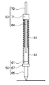
以下、図面を参照して本願発明の好適な実施形態について説明する。本発明の特徴は、接触子と、電気的接続装置の支持体とにあるため、本発明の接触子と支持体とを組み込むことができる全ての電気的接続装置に、本願発明を適用することができる。このため、本実施形態では、接触子と、電気的接続装置の支持体とを中心に説明する。図1は本実施形態に係る接触子と、電気的接続装置の支持体の一部とを示す要部断面図、図4は接触子を備えた支持体がベース板の下側に取り付けられた状態を示す側面図である。 Hereinafter, preferred embodiments of the present invention will be described with reference to the drawings. Since the feature of the present invention is the contact and the support of the electrical connection device, the present invention is applied to all electrical connection devices that can incorporate the contact and support of the present invention. Can do. For this reason, in this embodiment, it demonstrates centering around a contactor and the support body of an electrical connection apparatus. FIG. 1 is a cross-sectional view of a main part showing a contact according to the present embodiment and a part of a support body of an electrical connection device, and FIG. It is a side view which shows a state.
本実施形態の接触子1は、ポゴピンタイプの接触子である。この接触子1は、図1に示すように、スリーブ2と、第1のピン3と、第2のピン4と、第1のばね5と、第2のばね6とを備えて構成されている。
The
スリーブ2は、筒状の部材で、その内部に第1のピン3と、第2のピン4と、第1のばね5とが収納されている。スリーブ2の両端部はかしめられて、内部に収納された第1のピン3及び第2のピン4が抜け落ちないで出没可能に支持されている。スリーブ2は、その全長を短く形成され、内部に収納された第1のばね5も短く形成されている。
The
第1のピン3は、ベース板8側の電極であるランド部9に電気的に接触するためのピンである。この第1のピン3は、スリーブ2内に収納される基端部3Aと、スリーブ2の一端からランド部9側に出没可能に延出する接触棒部3Bとから構成されている。基端部3Aは、スリーブ2内にスライド可能に支持されている。接触棒部3Bは、基端部3Aから上方へ長く延びて形成され、第2のばね6を支える支持棒としても機能している。接触棒部3Bの先端部(上端部)がランド部9に直接接触される。
The
第2のピン4は、検査対象相手側の電極に電気的に接触するためのピンである。この第2のピン4は、スリーブ2内に収納される基端部4Aと、スリーブ2の他端から検査対象相手側に出没可能に延出する接触棒部4Bとから構成されている。基端部4Aは、スリーブ2内にスライド可能に支持されている。接触棒部4Bの先端部(下端部)が検査対象相手側の電極に直接接触される。
The
第1のばね5は、前記スリーブ2内の第1のピン3及び第2のピン4の間に設けられてこれら第1及び第2のピン3,4を互いに離間する方向に付勢するばねである。この第1のばね5は、その全長を短く形成され、第1のピン3と第2のピン4だけを支持している。即ち、第1のばね5の全長を短くして、この第1のばね5に第1及び第2のピン3,4を互いに離間する方向に付勢する機能のみを持たせている。このため、第1のばね5は、第1及び第2のピン3,4の出没するストロークを許容するだけの長さに設定されている。スリーブ2を支持するための付勢力は第2のばね6に委ねている。
The
第2のばね6は、前記スリーブ2を前記ランド部9側から付勢するためのばねである。第2のばね6は、前記スリーブ2の一端に外部から一体的に取り付けられている。この第2のばね6は、その内部に通された第1のピン3の接触棒部3Bに支持された状態で、先端部が前記ベース板8側に当接して、スリーブ2を後述する支持体11の貫通穴12内に押し込む方向に付勢してスリーブ2を支持している。さらに、第2のばね6は、スリーブ2の一端に取り付けられた状態でベース板8のランド部9に接触して、第1のピン3と共にランド部9に電気的に接続されている。
The
以上の構成の接触子1は支持体11に支持されている。支持体11は、図1,4に示すように、ベース板8の下側面に沿って配設されている。ベース板8は、装置本体側に取り付けられ、その下側面に、検査対象相手側の電極に電気信号を送信するための電極であるランド部9を備えている。支持体11は、検査対象相手側の形状に合わせて板状に形成されている。具体的には、検査対象相手側の表面に設けられたすべての電極に接触子1を接触させることができる大きさ及び形状に形成されている。支持体11は、2枚重ね構造になっている。これは、後述する貫通穴12を形成しやすくするためである。
The
支持体11には複数の貫通穴12が設けられている。貫通穴12は、ベース板8の各ランド部9及び検査対象相手側の各電極に対応した位置にそれぞれ設けられている。貫通穴12は、接触子1を支持するための穴である。貫通穴12は、下端支持穴部12Aと、中空部12Bと、上端支持穴部12Cとから構成されている。
The
下端支持穴部12Aは、検査対象相手側(図中の下側)に開口して形成され、接触子1の第2のピン4を出没可能に支持するための穴である。この下端支持穴部12Aは、接触子1の第2のピン4の接触棒部4Bの直径よりも僅かに大きい程度の大きさに設定されて、第2のピン4の接触棒部4Bをスライド可能に支持している。各下端支持穴部12Aは、検査対象相手側の各電極にそれぞれ対応した位置に設けられ、各第2のピン4の先端が検査対象相手側の各電極にそれぞれ接触するようになっている。
The lower end
中空部12Bは、接触子1を通すための空間である。中空部12Bは、接触子1との接触面積を少なくするために、接触子1のスリーブ2の外径よりも大きく形成されている。中空部12Bの下端底面部は、スリーブ2の下端を支持する下端支持部14となっている。具体的には、中空部12Bの下端底面部のうち、スリーブ2よりも小さい内径の下端支持穴部12Aの周囲が下端支持部14となっている。この下端支持部14が、スリーブ2の下端に当接した状態でこのスリーブ2の上端側から第2のばね6で押圧されることで、スリーブ2を貫通穴12内に支持されている。これにより、接触棒部4Bにストッパーを設ける必要がなくなり、省略している。
The
上端支持穴部12Cは、ベース板8のランド部9側に開口して形成され、接触子1を出し入れするための穴である。この上端支持穴部12Cに接触子1が外部から挿入されて、第2のばね6で支持される。この上端支持穴部12Cは、接触子1のスリーブ2の直径よりも僅かに大きい程度の大きさである、接触子1を出し入れ可能な大きさに形成されている。上端支持穴部12Cから挿入された接触子1は、第2のばね6で支持される。各上端支持穴部12Cは、ベース板8の各ランド部9にそれぞれ対応した位置に設けられている。これにより、上端支持穴部12Cから接触子1が挿入されて、第1のピン3の先端がベース板8のランド部9に接触された状態で、このランド部9側であるベース板8に接触子1の第2のばね6が当接して、接触子1を貫通穴12内に付勢して支持している。
The upper end
以上のように構成された接触子1及びこの接触子1を用いた電気的接続装置は次のようにして使用される。
The
支持体11の各貫通穴12に接触子1が挿入される。接触子1は、貫通穴12の上端支持穴部12Cからそのまま挿入されるだけである。全ての貫通穴12に接触子1を挿入し終わると、支持体11をベース板8の下側に取り付けて、各接触子1の接触棒部3Bを各ランド部9に接触させる。さらに、第2のばね6もランド部9に接触させる。これにより、接触棒部3Bと第2のばね6とがランド部9に電気的に接続される。なお、第2のばね6の直径が大きい場合は、接触棒部3Bのみが電気的に接続される。
The
さらに、第2のばね6は、ベース板8側に当接してスリーブ2を貫通穴12内に付勢する。これにより、スリーブ2の上端が第2のばね6で押された状態で、その下端が下端支持部14に当接して支持され、これら第2のばね6と下端支持部14とでスリーブ2(接触子1)が貫通穴12内に固定支持される。この状態で、第2のピン4の接触棒部4Bが下端支持穴部12Aから相手側の電極に向けて延出されている。
Further, the
次いで、ベース板8及び支持体11が検査対象相手側を覆うように重ねられ、検査対象相手側の各電極と、各接触子1の接触棒部4Bとが互いに接触される。
Next, the
これにより、検査対象相手側の各電極に接触した接触棒部4Bが貫通穴12内に押し込まれて第1のばね5を押し縮め、この第1のばね5が第1のピン3をランド部9側へ押圧して、検査対象相手側の各電極と各ランド部9とが電気的に接続される。次いで、検査信号等が印加されて、検査が行われる。
As a result, the contact bar portion 4B in contact with each electrode on the inspection object counterpart side is pushed into the through
また、メンテナンス等の際に接触子1を交換する場合、支持体11をベース板8から外し、貫通穴12から接触子1を抜き取って新しい接触子1を貫通穴12に挿入し、支持体11をベース板8の下側面に装着するだけで済む。
When exchanging the
以上のように、接触子1の第1のばね5には、スリーブ2内の第1のピン3と第2のピン4とを互いに離間する方向に付勢する機能のみを持たせて、スリーブ2を支持するための付勢力は第2のばね6に委ねているため、第1のばね5を短くすることができる。具体的には、現行モデルの電気的接続装置の接触子1の場合、12mmであるのが、本実施形態の電気的接続装置の接触子1の場合、8mm(図4参照)まで短くすることができる。
As described above, the
また、電気的接続装置の支持体11に備えた貫通穴12が、ランド部9側に接触子1を出し入れ可能に開口していて、接触子1を覆ってしまう構成にしなかったため、貫通穴12が浅くなり、支持体11を薄く成形できる。
Further, since the through
これにより、接触子1の全長が短くなった分と、貫通穴12が浅くなって支持体11を薄く成形できる分だけ、装置全体が薄くコンパクトになり、コスト低減を図ることができる。
As a result, the entire device becomes thin and compact as much as the entire length of the
また、接触子1を支持体11の貫通穴12に容易に挿入することができるため、電気的接続装置の組立作業性が大幅に向上する。
Further, since the
さらに、メンテナンス等の際に接触子1を交換する場合、貫通穴12から接触子1を抜き取って新しい接触子1を貫通穴12に挿入するだけで済むため、接触子1の交換作業性が大幅に向上する。
Furthermore, when the
[変形例]
前記実施形態では、支持体11を2枚重ね構造にしたが、図5に示すように、支持体11を1枚の部材で構成して、貫通穴12を下端支持穴部12Aと中空部12Bとから構成するようにしても良い。これにより、前記実施形態と同様の作用、効果を奏することができると共に、支持体11の部品点数を減らして、さらに薄くコンパクトにすることができる。
[Modification]
In the above embodiment, the
1:接触子、2:スリーブ、3:第1のピン、4:第2のピン、5:第1のばね、6:第2のばね、8:ベース板、9:ランド部、11:支持体、12:貫通穴、14:下端支持部。 1: contact, 2: sleeve, 3: first pin, 4: second pin, 5: first spring, 6: second spring, 8: base plate, 9: land portion, 11: support Body, 12: through hole, 14: lower end support.
Claims (3)
当該スリーブの一端に出没可能に支持されてランド部に接触する第1のピンと、
前記スリーブの他端に出没可能に支持されて検査対象相手側の電極に接触する第2のピンと、
前記スリーブ内の前記第1及び第2のピンの間に設けられてこれら第1及び第2のピンを離間する方向に付勢する第1のばねと、
前記スリーブの一端に外部から一体的に取り付けられて当該スリーブを前記ランド部側から付勢する第2のばねと
を備えて構成されたことを特徴とする接触子。 A cylindrical sleeve;
A first pin that is supported by one end of the sleeve so as to be able to protrude and come into contact with the land portion;
A second pin that is supported by the other end of the sleeve so as to protrude and come into contact with the electrode on the other side of the inspection object;
A first spring provided between the first and second pins in the sleeve and biasing the first and second pins away from each other;
And a second spring that is integrally attached to one end of the sleeve from the outside and biases the sleeve from the land portion side.
前記スリーブが、その両端部をかしめて前記第1及び第2のピンが抜け落ちないで出没可能に支持されたことを特徴とする接触子。 The contact according to claim 1,
2. A contact according to claim 1, wherein the sleeve is supported so that it can protrude and retract without crimping both ends thereof.
前記接触子として請求項1又は2に記載の接触子を用い、
前記支持体に備えた貫通穴の前記ランド部側の開口が前記接触子を出し入れ可能な大きさに形成されると共に前記貫通穴の前記検査対象相手側の開口が前記ピンを出没可能な大きさに形成され、
前記接触子の第2のばねが、前記ランド部側に当接して当該接触子を前記貫通穴内に付勢して支持することを特徴とする電気的接続装置。 A support body having a plurality of through holes, and a contactor inserted into each through hole of the support body so that a pin at one end is in contact with the land portion and a pin at the other end is in contact with the electrode on the other side of the inspection object Prepared,
Using the contact according to claim 1 or 2 as the contact,
The opening on the land portion side of the through hole provided in the support is formed to a size that allows the contactor to be taken in and out, and the opening on the counterpart side of the through hole to allow the pin to protrude and retract. Formed into
The electrical connection device, wherein the second spring of the contact is in contact with the land portion side and biases and supports the contact in the through hole.
Priority Applications (1)
| Application Number | Priority Date | Filing Date | Title |
|---|---|---|---|
| JP2008178242A JP5184996B2 (en) | 2008-07-08 | 2008-07-08 | Contactor and electrical connection device |
Applications Claiming Priority (1)
| Application Number | Priority Date | Filing Date | Title |
|---|---|---|---|
| JP2008178242A JP5184996B2 (en) | 2008-07-08 | 2008-07-08 | Contactor and electrical connection device |
Publications (2)
| Publication Number | Publication Date |
|---|---|
| JP2010020936A true JP2010020936A (en) | 2010-01-28 |
| JP5184996B2 JP5184996B2 (en) | 2013-04-17 |
Family
ID=41705632
Family Applications (1)
| Application Number | Title | Priority Date | Filing Date |
|---|---|---|---|
| JP2008178242A Expired - Fee Related JP5184996B2 (en) | 2008-07-08 | 2008-07-08 | Contactor and electrical connection device |
Country Status (1)
| Country | Link |
|---|---|
| JP (1) | JP5184996B2 (en) |
Cited By (4)
| Publication number | Priority date | Publication date | Assignee | Title |
|---|---|---|---|---|
| KR101247499B1 (en) | 2012-02-14 | 2013-04-03 | 주식회사 휴먼라이트 | Probe pin and method of manufacturing the same background of the invention |
| DE112016007382T5 (en) | 2016-10-26 | 2019-09-26 | Mitsubishi Electric Corporation | Inspection device and inspection method |
| CN113823936A (en) * | 2021-08-18 | 2021-12-21 | 国创移动能源创新中心(江苏)有限公司 | Flexible contactor and PDU equipment based on flexible contactor |
| KR20230013823A (en) * | 2021-07-20 | 2023-01-27 | 김철군 | Double pogo pin and test socket using this |
Citations (5)
| Publication number | Priority date | Publication date | Assignee | Title |
|---|---|---|---|---|
| JPH03127789U (en) * | 1990-04-06 | 1991-12-24 | ||
| JPH1186992A (en) * | 1997-09-05 | 1999-03-30 | Yokowo Co Ltd | Spring connector and electronic component mounting method using it |
| JP2002246097A (en) * | 2001-02-19 | 2002-08-30 | Matsushita Electric Ind Co Ltd | Electrical connection device, electrical connection method and component-mounting device |
| JP2003217726A (en) * | 2002-01-24 | 2003-07-31 | Yokowo Co Ltd | Connector |
| JP2007285939A (en) * | 2006-04-19 | 2007-11-01 | Matsushita Electric Ind Co Ltd | Inspection device and method of semiconductor integrated circuit device |
-
2008
- 2008-07-08 JP JP2008178242A patent/JP5184996B2/en not_active Expired - Fee Related
Patent Citations (5)
| Publication number | Priority date | Publication date | Assignee | Title |
|---|---|---|---|---|
| JPH03127789U (en) * | 1990-04-06 | 1991-12-24 | ||
| JPH1186992A (en) * | 1997-09-05 | 1999-03-30 | Yokowo Co Ltd | Spring connector and electronic component mounting method using it |
| JP2002246097A (en) * | 2001-02-19 | 2002-08-30 | Matsushita Electric Ind Co Ltd | Electrical connection device, electrical connection method and component-mounting device |
| JP2003217726A (en) * | 2002-01-24 | 2003-07-31 | Yokowo Co Ltd | Connector |
| JP2007285939A (en) * | 2006-04-19 | 2007-11-01 | Matsushita Electric Ind Co Ltd | Inspection device and method of semiconductor integrated circuit device |
Cited By (7)
| Publication number | Priority date | Publication date | Assignee | Title |
|---|---|---|---|---|
| KR101247499B1 (en) | 2012-02-14 | 2013-04-03 | 주식회사 휴먼라이트 | Probe pin and method of manufacturing the same background of the invention |
| DE112016007382T5 (en) | 2016-10-26 | 2019-09-26 | Mitsubishi Electric Corporation | Inspection device and inspection method |
| US10802047B2 (en) | 2016-10-26 | 2020-10-13 | Mitsubishi Electric Corporation | Inspection device and inspection method |
| KR20230013823A (en) * | 2021-07-20 | 2023-01-27 | 김철군 | Double pogo pin and test socket using this |
| KR102642002B1 (en) * | 2021-07-20 | 2024-02-27 | 김철군 | Double pogo pin and test socket using this |
| CN113823936A (en) * | 2021-08-18 | 2021-12-21 | 国创移动能源创新中心(江苏)有限公司 | Flexible contactor and PDU equipment based on flexible contactor |
| CN113823936B (en) * | 2021-08-18 | 2023-12-01 | 国创移动能源创新中心(江苏)有限公司 | Flexible contactor and PDU equipment based on flexible contactor |
Also Published As
| Publication number | Publication date |
|---|---|
| JP5184996B2 (en) | 2013-04-17 |
Similar Documents
| Publication | Publication Date | Title |
|---|---|---|
| EP2747210B1 (en) | Contactor | |
| KR100854267B1 (en) | Fabrication method of pogo pin and test socket using the same | |
| US20110248736A1 (en) | Probe pin and an ic socket with the same | |
| US20160154024A1 (en) | Inspection unit | |
| JP4448086B2 (en) | Inspection jig for printed wiring boards | |
| KR101974811B1 (en) | Integrated pogo pin capable of sigle body housing | |
| JP6026130B2 (en) | Contacts, connectors | |
| TWI548879B (en) | Spring sleeve probe | |
| JP2006266869A (en) | Contact pin and socket for electrical component | |
| JP5184996B2 (en) | Contactor and electrical connection device | |
| KR20110065047A (en) | Test socket, the fabrication method thereof and pogo pin | |
| JP6328925B2 (en) | Contact probe and socket for electrical parts | |
| JP7021874B2 (en) | Contact probes and inspection jigs | |
| US8159249B2 (en) | Inspection unit | |
| JP2008026248A (en) | Probe, probe unit therewith, probe card therewith, and manufacturing method of probe unit | |
| JP2006153723A (en) | Vertical coil spring probe and probe unit using the same | |
| JP6150666B2 (en) | Probe and probe manufacturing method | |
| JP2003172748A (en) | Conductive contact | |
| JP4745277B2 (en) | Vertical probe | |
| JP2011169595A (en) | Both-end-displacement type contact probe | |
| JP5567523B2 (en) | Connection pin | |
| KR101843474B1 (en) | Probe-pin with spring | |
| JP2006184285A (en) | Volute spring | |
| JP2007287427A (en) | Contact pin and socket for electrical component | |
| JP6658048B2 (en) | Inspection device, method of manufacturing inspection device |
Legal Events
| Date | Code | Title | Description |
|---|---|---|---|
| A621 | Written request for application examination |
Free format text: JAPANESE INTERMEDIATE CODE: A621 Effective date: 20110304 |
|
| A977 | Report on retrieval |
Free format text: JAPANESE INTERMEDIATE CODE: A971007 Effective date: 20120625 |
|
| A131 | Notification of reasons for refusal |
Free format text: JAPANESE INTERMEDIATE CODE: A131 Effective date: 20120703 |
|
| A521 | Request for written amendment filed |
Free format text: JAPANESE INTERMEDIATE CODE: A523 Effective date: 20120817 |
|
| TRDD | Decision of grant or rejection written | ||
| A01 | Written decision to grant a patent or to grant a registration (utility model) |
Free format text: JAPANESE INTERMEDIATE CODE: A01 Effective date: 20130108 |
|
| A61 | First payment of annual fees (during grant procedure) |
Free format text: JAPANESE INTERMEDIATE CODE: A61 Effective date: 20130117 |
|
| R150 | Certificate of patent or registration of utility model |
Ref document number: 5184996 Country of ref document: JP Free format text: JAPANESE INTERMEDIATE CODE: R150 Free format text: JAPANESE INTERMEDIATE CODE: R150 |
|
| FPAY | Renewal fee payment (event date is renewal date of database) |
Free format text: PAYMENT UNTIL: 20160125 Year of fee payment: 3 |
|
| R250 | Receipt of annual fees |
Free format text: JAPANESE INTERMEDIATE CODE: R250 |
|
| R250 | Receipt of annual fees |
Free format text: JAPANESE INTERMEDIATE CODE: R250 |
|
| LAPS | Cancellation because of no payment of annual fees |