JP2010019289A - Fluid dynamic pressure bearing device - Google Patents
Fluid dynamic pressure bearing device Download PDFInfo
- Publication number
- JP2010019289A JP2010019289A JP2008178373A JP2008178373A JP2010019289A JP 2010019289 A JP2010019289 A JP 2010019289A JP 2008178373 A JP2008178373 A JP 2008178373A JP 2008178373 A JP2008178373 A JP 2008178373A JP 2010019289 A JP2010019289 A JP 2010019289A
- Authority
- JP
- Japan
- Prior art keywords
- bearing
- peripheral surface
- bearing sleeve
- lid member
- dynamic pressure
- Prior art date
- Legal status (The legal status is an assumption and is not a legal conclusion. Google has not performed a legal analysis and makes no representation as to the accuracy of the status listed.)
- Granted
Links
Images

Abstract
Description
本発明は、軸部材の外周面と軸受スリーブの内周面との間のラジアル軸受隙間に生じる流体膜の動圧作用で軸部材を回転自在に支持する流体動圧軸受装置に関する。 The present invention relates to a fluid dynamic bearing device that rotatably supports a shaft member by a dynamic pressure action of a fluid film generated in a radial bearing gap between an outer peripheral surface of the shaft member and an inner peripheral surface of a bearing sleeve.
流体動圧軸受装置は、その高回転精度および静粛性から、情報機器(例えばHDD)の磁気ディスク駆動装置、CD・DVD・ブルーレイディスク等の光ディスク駆動装置、若しくはMD・MO等の光磁気ディスク駆動装置等のスピンドルモータ用、レーザビームプリンタ(LBP)のポリゴンスキャナモータ用、プロジェクタのカラーホイールモータ用、又は電気機器の冷却等に使用されるファンモータなどの小型モータ用として使用されている。 Due to its high rotational accuracy and quietness, the fluid dynamic pressure bearing device is driven by a magnetic disk drive for information equipment (for example, HDD), an optical disk drive such as CD / DVD / Blu-ray disc, or a magneto-optical disk drive such as MD / MO It is used for spindle motors of devices, for polygon scanner motors of laser beam printers (LBP), for color wheel motors of projectors, or for small motors such as fan motors used for cooling electrical equipment.
例えば、特許文献1には、軸部材と、内周に軸部材を挿入した軸受スリーブと、内周に軸受スリーブを保持した筒状のハウジングと、ハウジングの一方の開口部を閉塞する蓋部材とを有する流体動圧軸受装置が示されている。蓋部材はハウジングの内周面に接着や圧入、あるいは加締め等の適宜の手段で固定されている。
For example,
上記の流体動圧軸受装置に衝撃荷重が加わると、軸部材の端部が蓋部材に突き当たることがある。特に、HDDのディスク駆動装置に組み込まれる流体動圧軸受装置では、HDDの大容量化のためにディスクが複数枚搭載されると、軸部材側の重量が増大して蓋部材に加わる衝撃が大きくなる。このような場合、蓋部材の固定強度が重要となる。上記特許文献1の流体動圧軸受装置のようにハウジングの内周面に蓋部材を固定する場合、蓋部材の肉厚を増せばハウジングと蓋部材との固定面積が拡大され、蓋部材の固定強度を高めることができる。しかし、蓋部材の肉厚を増すと軸受装置の軸方向寸法の拡大やラジアル軸受部の軸受スパンの縮小を招くため、蓋部材をむやみに厚肉化することはできない。
When an impact load is applied to the fluid dynamic bearing device, the end of the shaft member may abut against the lid member. In particular, in a fluid dynamic pressure bearing device incorporated in a disk drive device of an HDD, when a plurality of disks are mounted to increase the capacity of the HDD, the weight on the shaft member side increases and the impact applied to the lid member is large. Become. In such a case, the fixing strength of the lid member is important. When the lid member is fixed to the inner peripheral surface of the housing as in the fluid dynamic pressure bearing device of
本発明の課題は、大型化や軸受性能の低下を招くことなく、流体動圧軸受装置の蓋部材の固定強度を高めることにある。 An object of the present invention is to increase the fixing strength of a lid member of a fluid dynamic pressure bearing device without causing an increase in size or a decrease in bearing performance.
前記課題を解決するために、本発明は、軸部材と、内周に軸部材を挿入した軸受スリーブと、軸受スリーブを外周から保持し、軸方向両端を開口した保持部材と、軸受スリーブの外周面に固定され、軸受スリーブの軸方向一方の開口部を閉塞する蓋部材と、軸部材の外周面と軸受スリーブの内周面との間のラジアル軸受隙間に生じる流体膜で軸部材をラジアル方向に支持するラジアル軸受部とを有する流体動圧軸受装置を提供する。 In order to solve the above-described problems, the present invention provides a shaft member, a bearing sleeve in which the shaft member is inserted on the inner periphery, a holding member that holds the bearing sleeve from the outer periphery and that is open at both ends in the axial direction, and an outer periphery of the bearing sleeve. The cover member that is fixed to the surface and closes one opening of the bearing sleeve in the axial direction and the fluid film generated in the radial bearing gap between the outer peripheral surface of the shaft member and the inner peripheral surface of the bearing sleeve in the radial direction A fluid dynamic pressure bearing device having a radial bearing portion supported on the surface is provided.
このように、本発明の流体動圧軸受装置では、蓋部材を軸受スリーブの外周面に固定しているため、これらの固定面積を拡大して蓋部材の固定強度の向上を図っても、軸受装置の軸方向寸法の拡大やラジアル軸受部の軸受スパンの縮小を招くことはない。すなわち、蓋部材で軸受スリーブの一端開口部を閉塞しつつ、蓋部材を軸受スリーブの外周面に固定しようとすると、開口部を閉塞する部分(例えば図2のプレート部10a参照)と、外周面に固定される部分(例えば図2の円筒部10b参照)とを要することとなる。両者の固定面積を拡大するには、固定される部分を軸方向に延ばして蓋部材と軸受スリーブ外周面との接触面積を拡大すればよい。従って、軸受装置の軸方向寸法やラジアル軸受部の軸受スパンに影響するプレート部の肉厚を変えることなく、蓋部材と軸受スリーブとの固定強度を高めることができる。
As described above, in the fluid dynamic pressure bearing device of the present invention, the lid member is fixed to the outer peripheral surface of the bearing sleeve. Therefore, even if the fixing area of the lid member is expanded to improve the fixing strength of the lid member, the bearing There is no increase in the axial dimension of the device or reduction in the bearing span of the radial bearing portion. That is, when the lid member is closed to the outer peripheral surface of the bearing sleeve while closing the one end opening of the bearing sleeve with the lid member, the portion that closes the opening (see, for example, the
軸部材にフランジ部を設け、フランジ部の両端面が面するスラスト軸受隙間の流体膜で軸部材をスラスト方向に支持するスラスト軸受部を設けた場合、スラスト軸受隙間の隙間幅は高精度に設定する必要がある。このとき、各部材を高精度に加工すればスラスト軸受隙間の幅精度を高めることができるが、かかる高精度な加工はコスト高を招く。この点に鑑み、保持部材と蓋部材との間に軸方向隙間を設ければ、両者の軸方向の相対的な接近移動が許容されるため、以下のような方法によりスラスト軸受隙間の幅設定を行うことができる。まず、フランジ部の両端面に軸受スリーブ及び蓋部材を当接させて、スラスト軸受隙間の隙間幅を0の状態とし、この状態から軸受スリーブから離隔する方向に蓋部材を所定量だけ移動させる。この方法によれば、各部材の精度に依存することなく、蓋部材の移動量でスラスト軸受隙間の幅設定を行うことができるため、各部品の加工精度が緩和され、加工コストを低減することができる。 When the shaft member is provided with a flange, and a thrust bearing that supports the shaft member in the thrust direction with a fluid film of the thrust bearing gap facing both end faces of the flange, the clearance width of the thrust bearing gap is set with high accuracy. There is a need to. At this time, if each member is processed with high accuracy, the width accuracy of the thrust bearing gap can be increased, but such high-precision processing leads to high costs. In view of this point, if an axial gap is provided between the holding member and the lid member, relative approach movement of the two in the axial direction is allowed. Therefore, the width of the thrust bearing gap is set by the following method. It can be performed. First, the bearing sleeve and the lid member are brought into contact with both end faces of the flange portion so that the gap width of the thrust bearing gap is zero, and the lid member is moved by a predetermined amount in a direction away from the bearing sleeve from this state. According to this method, since the width of the thrust bearing gap can be set by the amount of movement of the lid member without depending on the accuracy of each member, the processing accuracy of each part is relaxed and the processing cost is reduced. Can do.
例えば、軸受スリーブを多孔質体(例えば焼結金属)で形成すれば、軸受スリーブの内部空孔に含浸した潤滑流体を軸受隙間に逐次供給することができるため、潤滑性を高めることができる。このとき、保持部材と蓋部材との間の前記軸方向隙間から露出した軸受スリーブの外周面を封止すれば、軸受スリーブの表面開孔からにじみ出た潤滑流体が外部へ漏れ出す事態を防止できる。 For example, if the bearing sleeve is formed of a porous body (for example, sintered metal), the lubricating fluid impregnated in the internal holes of the bearing sleeve can be sequentially supplied to the bearing gap, so that the lubricity can be improved. At this time, if the outer peripheral surface of the bearing sleeve exposed from the axial gap between the holding member and the lid member is sealed, it is possible to prevent the lubricating fluid that has oozed out from the surface opening of the bearing sleeve from leaking to the outside. .
一般に、金属材料同士の接着強度は、例えば金属材料と樹脂材料との接着強度に比べて高いため、軸受スリーブと蓋部材とを共に金属材料で形成して両者を接着固定すれば、強固に固定することができる。 In general, the adhesive strength between metal materials is higher than the adhesive strength between metal materials and resin materials, for example, so if both the bearing sleeve and lid member are made of metal materials and bonded together, they are firmly fixed. can do.
蓋部材を軸受スリーブの外周面に固定すると、固定による影響(例えば、接着剤の固化による収縮や、圧入による圧迫力)が軸受スリーブの内周面まで及び、内周面が縮径することがある。このとき、ラジアル軸受部の軸方向領域内で軸受スリーブの内周面の縮径量が異なると、ラジアル軸受隙間の隙間幅が軸方向で不均一となり、軸受性能が悪化する恐れがある。そこで、蓋部材の端部をラジアル軸受部の軸方向領域を越えた位置まで延ばせば、ラジアル軸受部の外径側が全て蓋部材で覆われるため、軸受スリーブの内周面をラジアル軸受部の軸方向全域に亘って一律に縮径させることができる。これにより、ラジアル軸受隙間の隙間幅が軸方向で一定となり、優れた軸受性能を得ることができる。また、保持部材の端部をラジアル軸受部の軸方向領域を越えた位置まで延ばすことによっても、上記と同様の効果を得ることができる。 When the lid member is fixed to the outer peripheral surface of the bearing sleeve, the influence of the fixing (for example, shrinkage due to solidification of the adhesive or pressing force due to press-fitting) may reach the inner peripheral surface of the bearing sleeve and the inner peripheral surface may be reduced in diameter. is there. At this time, if the amount of diameter reduction of the inner peripheral surface of the bearing sleeve is different in the axial region of the radial bearing portion, the gap width of the radial bearing gap becomes non-uniform in the axial direction, which may deteriorate the bearing performance. Therefore, if the end of the lid member is extended to a position beyond the axial region of the radial bearing portion, the outer diameter side of the radial bearing portion is entirely covered with the lid member, so the inner peripheral surface of the bearing sleeve is the shaft of the radial bearing portion. The diameter can be uniformly reduced over the entire direction. Thereby, the gap width of the radial bearing gap is constant in the axial direction, and excellent bearing performance can be obtained. Further, the same effect as described above can be obtained by extending the end of the holding member to a position beyond the axial region of the radial bearing.
ステータコイルを取り付けるためのブラケットを設ける場合、このブラケットに蓋部材の外周面を固定すれば、蓋部材の固定強度をより一層高めることができる。 When a bracket for attaching the stator coil is provided, the fixing strength of the lid member can be further increased by fixing the outer peripheral surface of the lid member to the bracket.
以上のように、本発明によれば、軸受装置の大型化や軸受性能の低下を招くことなく、流体動圧軸受装置の蓋部材の固定強度を高めることができる。 As described above, according to the present invention, it is possible to increase the fixing strength of the lid member of the fluid dynamic pressure bearing device without causing an increase in the size of the bearing device or a decrease in bearing performance.
以下、本発明の実施形態を図面に基づいて説明する。 Hereinafter, embodiments of the present invention will be described with reference to the drawings.
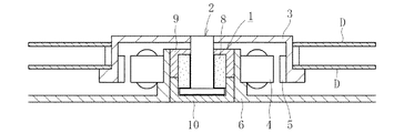
図1は、本発明の一実施形態に係る流体動圧軸受装置1を組込んだ情報機器用スピンドルモータの一構成例を概念的に示している。このスピンドルモータは、HDD等のディスク駆動装置に用いられるもので、軸部材2を回転自在に支持する流体動圧軸受装置1と、軸部材2の上端部に固定されたディスクハブ3と、半径方向のギャップを介して対向させたステータコイル4およびロータマグネット5と、モータブラケット6とを備えている。ステータコイル4はモータブラケット6の外周に取付けられ、ロータマグネット5はディスクハブ3の内周に取付けられている。流体動圧軸受装置1は、モータブラケット6の内周に固定される。ディスクハブ3には、情報記録媒体としてのディスクDが1枚又は複数枚(本実施形態では2枚)保持され、図示しないクランプ装置で固定される。ステータコイル4に通電すると、ロータマグネット5が回転し、これに伴って、ディスクハブ3およびディスクハブ3に保持されたディスクDが軸部材2と一体に回転する。
FIG. 1 conceptually shows a configuration example of a spindle motor for information equipment incorporating a fluid dynamic bearing
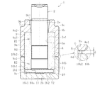
図2に示す流体動圧軸受装置1は、軸部材2と、内周に軸部材2を挿入した軸受スリーブ8と、軸受スリーブ8を外周から保持し、軸方向両端を開口した保持部材9と、軸受スリーブ8の軸方向一方の開口部を閉塞する蓋部材10とを有する。尚、説明の便宜上、軸方向で軸受スリーブ8の開口側を上側、閉塞側を下側と言うものとする。
A fluid dynamic bearing
軸部材2は、略円筒状の軸部2aと、軸部2aの下端に設けられたフランジ部2bとを有する。軸部2a及びフランジ部2bは耐摩耗性に富む金属材料(例えばSUS鋼)でそれぞれ別体に形成された後、例えば溶接により結合される。
The
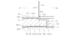
フランジ部2bには、上側端面2b1と下側端面2b2とに開口した連通孔11が形成される。詳しくは、連通孔11は径方向部11a及び軸方向部11bとを有し、フランジ部2bの上側端面2b1と下側端面2b2とで異なる径方向位置に開口する。さらに詳しくは、図5に示すように、連通孔11の一端が、フランジ部2bの上側端面2b1と軸受スリーブ8の下側端面8cの内周チャンファ8c2と軸部2aの下端部に設けられたヌスミ部2a2とで形成される空間に開口し、連通孔の他端が、フランジ部2bの下側端面2b2と蓋部材10のプレート部10aの上側端面10a1との間の空間Pのうち、第2スラスト軸受部T2の内径側の領域に開口している。図示例では第2スラスト軸受部T2の内径側に隣接した位置に連通孔11の他端が開口している。連通孔11は、予めフランジ部2bに、径方向部11aとなる径方向溝と軸方向部11bとなる軸方向孔を形成した後、フランジ部2bと軸部2aとを接合することにより形成される。
The
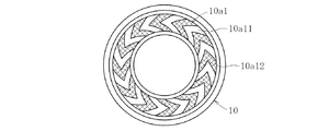
図3に示すように、軸受スリーブ8は、多孔質体、例えば銅を主成分とする焼結金属で円筒状に形成される。この他、軸受スリーブ8を他の金属や樹脂、あるいはセラミック等で形成することも可能である。軸受スリーブ8の内周面8a及び外周面8dは、共に軸方向で径方向寸法を一定とした円筒面状に形成される。また、軸受スリーブ8の上側端面8b及び8cには、それぞれ内周チャンファ及び外周チャンファが形成される。
As shown in FIG. 3, the
軸受スリーブ8の内周面8aには、ラジアル軸受隙間の流体膜(油膜)に動圧作用を発生させるためのラジアル動圧発生部が形成され、本実施形態では図3(a)に示すように、ヘリングボーン形状の動圧溝8a1、8a2が、軸方向に離隔した2箇所の領域に形成される。2つの動圧溝領域のうち、動圧溝8a1、8a2を除くクロスハッチングを付した部分は丘部となる。上側の動圧溝8a1は軸方向非対称形状に形成され、具体的には、丘部の軸方向略中央部に形成された帯状部分に対して、上側の溝の軸方向寸法X1が下側の溝の軸方向寸法X2よりも大きくなっている(X1>X2)。下側の動圧溝8a2は軸方向対称形状に形成される。
On the inner
軸受スリーブ8の下側端面8cには、スラスト軸受隙間の油膜に動圧作用を発生させるためのスラスト動圧発生部が形成され、本実施形態では図3(b)に示すように、へリングボーン形状で、V字状に屈曲した動圧溝8c1と丘部8c2を円周方向に交互に配列した構成を有する。
The
保持部材9は、軸方向両端を開口した筒状を成し、図示例では肉厚が一定である円筒状を成した円筒部9aと、円筒部9aの上端部から内径側に延びたシール部9bとを有する。円筒部9aは軸受スリーブ8を外周から保持し、その下端部9a1は第1ラジアル軸受部R1を越えて下側まで延びている。円筒部9aの内周面9a2および外周面9a3は、それぞれ軸方向で一定径の円筒面状を成している。シール部9bの内周面9b1は、下方へ向けて漸次縮径したテーパ面状に形成され、このテーパ状内周面9b1と軸部2aの外周面2a1との間に下方へ向けて径方向寸法を漸次縮小した楔状のシール空間Sが形成される。シール部9bで密封された軸受の内部空間は潤滑油で満たされる。シール空間Sには、軸受内部に満たされた潤滑油の油面(気液界面)が形成され、楔状のシール空間Sの毛細管力の引き込み作用により、油面は常にシール空間Sに保持される。シール空間Sの容積は、温度変化に伴って軸受内部に充満した潤滑油が膨張、収縮した場合でも、潤滑油の油面が常にシール空間Sの範囲内に保持できるように設定される。
The holding
円筒部9aとシール部9bの境界となる保持部材9の上端外径側では、角部が肉取りされている。この肉取り部9cによって、円筒部9aからシール部9bにかけての領域で保持部材9の肉厚がほぼ均一化されるので、樹脂の成形収縮によるシール部9bの内周面9b1の変形を抑制し、シール空間Sの形状精度を確保することができる。
On the outer diameter side of the upper end of the holding
保持部材9は、軸受スリーブ8をインサート部品とした樹脂の射出成形により、円筒部9a及びシール部9bを一体に形成される。保持部材9の樹脂材料は特に限定されず、例えば液晶ポリマー(LCP)、ポリフェニレンサルファイド(PPS)、ポリエーテルエーテルケトン(PEEK)等の結晶性樹脂、あるいはポリフェニルサルフォン(PPSU)、ポリエーテルサルフォン(PES)、ポリエーテルイミド(PEI)等の非晶性樹脂をベース樹脂とする樹脂組成物が使用可能である。この樹脂材料には、目的に応じて各種充填材を適量配合することができ、例えば、ガラス繊維等の繊維状充填材、チタン酸カリウム等のウィスカ状充填材、マイカ等の鱗片状充填材、カーボン繊維、カーボンブラック、黒鉛、カーボンナノマテリアル、各種金属粉等の繊維状または粉末状の導電性充填材などを配合することができる。
The holding
蓋部材10は、軸受スリーブ8の外周面8dに嵌合固定され、軸受スリーブ8の下側開口部を閉塞する。図示例では、蓋部材10は略円盤状のプレート部10aと、プレート部10aの外径端から上方へ延びた筒状部10bとを有する。蓋部材10は、例えば金属材料のプレス加工により、プレート部10a及び筒状部10bとが一体に形成される。
The
プレート部10aの上側端面10a1には、スラスト軸受隙間の油膜に動圧作用を発生させるスラスト動圧発生部が形成され、本実施形態では図4に示すように、へリングボーン形状で、V字状に屈曲した動圧溝10a11と丘部10a12を円周方向に交互に配列した構成を有する。
The upper end face 10a1 of the
筒状部10bの内周面10b1は、軸受スリーブ8の外周面8dに、例えば接着により固定される。筒状部10bの上端部10b2は、第2ラジアル軸受部R2を越えて上方まで延び、保持部材9の下端部9a1と軸方向隙間δを介して対向する(図2の拡大図参照)。この軸方向隙間δは、例えば接着剤Gにより全周を封止されている。
The inner peripheral surface 10b1 of the
蓋部材10と保持部材9との間に軸方向隙間δを設けることで、両者を軸方向に相対的に接近させることができるため、以下に示すような方法で蓋部材10を軸受スリーブ8に固定することができる。まず、予め接着剤を塗布した軸受スリーブ8の外周面8dに蓋部材10の筒状部10bの内周面10b1を嵌合し、フランジ部2bの両端面2b1・2b2に軸受スリーブ8及び蓋部材10のプレート部10aを当接させる(すなわちスラスト軸受隙間の隙間幅が0の状態にする)。このとき、蓋部材10の上端部10b2と保持部材9の下端部9a1とが接触しないように各部品の寸法を設定する。その後、各スラスト軸受隙間の隙間幅の合計量の分だけ蓋部材10を保持部材9に対して下方向(保持部材9と離反する方向)に引き戻し、この状態で接着剤を固化させる。このように、蓋部材10の移動量でスラスト軸受隙間の幅設定を行うことにより、各部品の加工精度が緩和され、加工コストを低減できる。
Since the axial gap δ is provided between the
こうして蓋部材10を軸受スリーブ8の外周に固定する際、軸受スリーブ8の外周面8dに接着剤が塗布されるため、外周面8dの表面開孔が封止される。また、蓋部材10の筒状部10bを下方から嵌合させることで、軸受スリーブ8の外周面8dの接着剤の一部を筒状部10bの上端部10b2で捕捉され、この捕捉された接着剤が保持部材9の下端部9a1との間の軸方向隙間δに配される。これにより軸方向隙間δが接着剤で封止され、軸方向隙間δから露出した軸受スリーブ8の外周面の表面開孔から滲み出した潤滑油が外部へ漏れ出す恐れを回避できる。尚、蓋部材10を軸受スリーブ8に固定したあと、さらに軸方向隙間δを接着剤で埋めて確実に封止するようにしてもよい。また、接着剤による封止に限らず、例えば樹脂材料で封止してもよい。
When the
筒状部10bの外周面10b3は、モータブラケット6の内周面6aに、例えば接着により固定される。このように、蓋部材10を軸受スリーブ8と固定するだけでなく、モータブラケット6とも接着固定することにより、蓋部材10の固定強度を高め、抜け耐力を向上させることができる。このとき、蓋部材10の外周面10b3と保持部材9の外周面9a3とを同一径に設定すれば、両者をブラケット6の内周面に固定しやすくなるため、流体動圧軸受装置1とモータブラケット6との固定強度を高めることができる。また、上記のように蓋部材10を金属材料で形成することで、ディスクDが回転することにより帯電した静電気を、軸部材2→蓋部材10→モータブラケット6という経路を介して外部へ放電することができる。これにより、保持部材9を形成する材料に導電性は要求されず、材料選択の幅が広がるため、例えば、保持部材9の樹脂材料に充填剤として加えられるカーボン繊維等を少なくしたり、あるいは省略したりすることができる。このように、比較的高価な材料であるカーボン繊維等の使用量を低減することで、材料コストを抑えることができる。
The outer peripheral surface 10b3 of the
上記構成の流体動圧軸受装置1の内部空間、すなわち、保持部材9及び蓋部材10で密閉された空間には、軸受スリーブ8の内部空孔を含め、潤滑流体として例えば潤滑油が満たされる。このとき、導電性を有する潤滑流体を用いれば、軸部材2の回転時に非接触状態となる回転側の軸部材2と固定側の軸受スリーブ8及び蓋部材10との間で通電することが可能となり、軸部材2側で発生した静電気を蓋部材10を介して放電することができる。
The internal space of the fluid
上記構成の流体動圧軸受装置1において、軸部材2が回転すると、軸受スリーブ8の内周面8aと軸部2aの外周面2a1との間にラジアル軸受隙間が形成される。このラジアル軸受隙間の油膜の圧力が動圧溝8a1、8a2により高められ、これにより軸部材2をラジアル方向に非接触支持する第1ラジアル軸受部R1及び第2ラジアル軸受部R2が構成される。これと同時に、軸部材2のフランジ部2bの上側端面2b1と軸受スリーブ8の下側端面8cとの間、及び、軸部材2のフランジ部2bの下側端面2b2と蓋部材10のプレート部10aの上側端面10a1との間に、それぞれスラスト軸受隙間が形成される。各スラスト軸受隙間の油膜の圧力が動圧溝8c1、10a11により高められ、これにより軸部材2をスラスト方向に非接触支持する第1スラスト軸受部T1及び第2スラスト軸受部T2が構成される。
In the fluid
ところで、蓋部材10の筒状部10bを軸受スリーブ8の外周面8dに固定すると、接着剤の固化時の収縮や圧入時の圧迫力により軸受スリーブ8が外径側から圧迫され、内周面8aが縮径することがある。このとき、上記のように、蓋部材10の上端部10b2が第2ラジアル軸受部R2を越えて上方まで達し、第2ラジアル軸受部R2の外径側が全て蓋部材10の筒状部10bで覆われているため、第2ラジアル軸受部R2を構成する軸受スリーブ8のラジアル軸受面(動圧溝8a2形成領域)が軸方向で一様に圧迫される。このため、ラジアル軸受隙間の隙間幅が軸方向で異なることはなく、蓋部材10の固定によるラジアル軸受隙間の幅精度の低下を抑えることができる。
By the way, when the
また、保持部材9の成形収縮により軸受スリーブ8が外径側から圧迫され、内周面8aが縮径することがある。このとき、上記のように、保持部材9の下端部9a1が第1ラジアル軸受部R1を越えて下方まで達し、第1ラジアル軸受部R1の外径側が全て保持部材9の円筒部9aで覆われているため、第1ラジアル軸受部R1を構成する軸受スリーブ8のラジアル軸受面(動圧溝8a1形成領域)が軸方向で一様に圧迫される。このため、軸受スリーブ8をインサート部品とした保持部材9の射出成形によるラジアル軸受隙間の幅精度の低下を抑えることができる。特に、図2に示すように、軸受スリーブ8の外径側において円筒部9aの肉厚が軸方向で一定であることにより、円筒部9aの成形収縮量が軸方向で一定となるため、軸受スリーブ8が軸方向で一様に圧迫される。
Further, the
また、この実施形態では、第1ラジアル軸受部R1の動圧溝8a1が軸方向非対称(X1>X2)に形成されているため(図3参照)、軸部材2の回転時、動圧溝8a1の上側の溝による潤滑油の引き込み力(ポンピング力)は、下側の溝の引き込み力に比べて相対的に大きくなる。この引き込み力の差圧によって、第1ラジアル軸受部R1のラジアル軸受隙間の潤滑油が下方に押し込まれ、軸受内部の閉塞側の空間、特に、フランジ部2bの下側端面2b2と蓋部材10のプレート部10aの上側端面10a1との間の空間(底面空間P、図3参照)の圧力が高められ、この閉塞空間Pにおいて負圧による気泡の生成を防止できる。
In this embodiment, since the dynamic pressure groove 8a1 of the first radial bearing portion R1 is formed to be axially asymmetric (X1> X2) (see FIG. 3), the dynamic pressure groove 8a1 is rotated when the
しかし、底面空間Pの圧力が過度に高まると、軸部材2の浮上力が大きくなり過ぎ、フランジ部2bの上側端面2b1と軸受スリーブ8の下側端面8cとの接触が多くなってこれらの面の早期の摩耗を招くことになる。本実施形態では、図5に示すように、フランジ部2bの上側端面2b1と下側端面2b2とに開口した連通孔11を設けることにより、底面空間Pをフランジ部2bの上側端面2b1と軸受スリーブ8の下側端面8cとの間の空間と連通することができるため、底面空間Pの圧力をフランジ部2bの上側端面2b1側の空間に逃がすことができ、底面空間Pの圧力を適正範囲内に維持することができる。
However, if the pressure in the bottom space P is excessively increased, the floating force of the
上記のように本発明では、底面空間Pの圧力が高くなる傾向にあるので、第2スラスト軸受部T2の動圧溝10a11を従来品で多用されるポンプインタイプのスパイラル形状にすると、スラスト軸受隙間の油が内径側に押し込まれるため、底面空間Pの圧力増大を助長することになる。これを回避するため、第2スラスト軸受部の動圧溝10a11は、上記のとおりへリングボーン形状(図4参照)にするのが望ましい。上側の第1スラスト軸受部T1では、この種の問題を生じないので、図3(b)に示すへリングボーン形状の動圧溝8c1に代えて、ポンプインタイプのスパイラル形状の動圧溝を採用することもできる。 As described above, in the present invention, the pressure in the bottom space P tends to increase. Therefore, when the dynamic pressure groove 10a11 of the second thrust bearing portion T2 is formed into a pump-in type spiral shape often used in conventional products, a thrust bearing is provided. Since the oil in the gap is pushed into the inner diameter side, the pressure increase in the bottom space P is promoted. In order to avoid this, it is desirable that the dynamic pressure groove 10a11 of the second thrust bearing portion has a herringbone shape (see FIG. 4) as described above. Since the upper first thrust bearing portion T1 does not cause this kind of problem, a pump-in type spiral-shaped dynamic pressure groove is used instead of the herringbone-shaped dynamic pressure groove 8c1 shown in FIG. It can also be adopted.
本発明は、上記の実施形態に限られない。以下、本発明の他の実施形態を説明する。尚、以下の説明において、上記実施形態と同様の構成、機能を有する部位には同一の符号を付して、説明を省略する。 The present invention is not limited to the above embodiment. Hereinafter, other embodiments of the present invention will be described. In the following description, parts having the same configuration and function as those of the above embodiment are denoted by the same reference numerals, and the description thereof is omitted.
上記の実施形態では、保持部材9の射出材料として樹脂を使用しているが、これに限らず、例えば、マグネシウム合金やアルミニウム合金等の低融点金属材料が使用可能である。また、上記の実施形態では、軸受スリーブ8をインサート部品として保持部材9を射出成形しているが、これらを別体に形成してもよい。この場合、金属紛とバインダーの混合物で射出成形した後、脱脂・焼結するいわゆるMIM成形や、金属材料、例えば真ちゅう等の軟質金属のプレス成形で保持部材9を形成することもできる。また、保持部材9の円筒部9a及びシール部9bは必ずしも一体に形成する必要はなく、これらを別体に形成することもできる。
In the above embodiment, the resin is used as the injection material of the holding
また、上記の実施形態では、蓋部材10を軸受スリーブ8に固定する際、予め接着剤を塗布した軸受スリーブ8の外周面8dに蓋部材10の筒状部10bを嵌合させた場合を示したが、これに限られない。例えば、先に蓋部材10と軸受スリーブ8とを嵌合させ、スラスト軸受隙間の幅設定を行った後に、軸方向隙間δから接着剤を供給し、軸受スリーブ8の外周面8dと筒状部10bの内周面10b1との間の微小隙間の毛細管力で接着剤を引き込むことで両者を固定してもよい。この場合、軸方向隙間δから露出した軸受スリーブ8の外周面8dが封止されるまで接着剤を供給すればよい。また、上記実施形態では、蓋部材10と軸受スリーブ8とを接着により固定した場合を示したが、これに限らず、例えば圧入や圧入接着、あるいは溶接等の手段で固定してもよい。接着剤を使用せずに固定する場合は、両者の固定が完了した後に軸方向隙間δから接着剤や樹脂を供給して、軸受スリーブ8の外周面8dを封止すればよい。
Moreover, in said embodiment, when fixing the
また、上記の実施形態では、軸部材2のフランジ部2bに連通孔11を設けるために、軸部2a及びフランジ部2bを別体に形成しているが、連通孔11を形成する必要がない場合は、例えば軸部2a及びフランジ部2bを金属材料の鍛造加工等で一体に形成してもよい。
Further, in the above embodiment, the
また、以上の実施形態では、ラジアル軸受部R1・R2及びスラスト軸受部T1・T2の動圧発生部がそれぞれ軸受スリーブ8の内周面8a、下側端面8c、及び蓋部材10のプレート部10aの上側端面10a1に形成されているが、これらの面と軸受隙間を介して対向する面、すなわち軸部2aの外周面2a1、フランジ部2bの上側端面2b1及び下側端面2b2に形成してもよい。
In the above embodiment, the dynamic pressure generating portions of the radial bearing portions R1 and R2 and the thrust bearing portions T1 and T2 are the inner
また、以上の実施形態では、ラジアル軸受部R1・R2のラジアル動圧発生部として、ヘリングボーン形状の動圧溝が例示されているが、これに限らず、例えば、いわゆるステップ軸受や波型軸受、あるいは多円弧軸受を採用することもできる。また、軸受スリーブ8の内周面8a及び軸部材2の外周面2a1の双方を円筒面とした、いわゆる真円軸受を、ラジアル軸受部R1・R2として採用することもできる。この場合、ラジアル軸受隙間の流体膜に積極的に動圧作用を発生させる動圧発生部は有さないが、軸部材の回転時には、潤滑流体の粘性により流体膜に動圧作用が発生し、ラジアル軸受部R1・R2が構成される。
Further, in the above embodiment, the herringbone-shaped dynamic pressure grooves are exemplified as the radial dynamic pressure generating portions of the radial bearing portions R1 and R2. However, the present invention is not limited to this, for example, so-called step bearings and wave-shaped bearings. Alternatively, a multi-arc bearing can be employed. Also, so-called perfect circular bearings in which both the inner
また、以上の実施形態では、スラスト軸受部T1・T2のスラスト動圧発生部として、スパイラル形状の動圧溝が例示されているが、これに限らず、例えばステップ軸受や波型軸受を採用することもできる。あるいは、スラスト軸受部T1・T2として、軸部材の端部を接触支持するピボット軸受を採用することもできる。 In the above embodiment, the spiral dynamic pressure grooves are exemplified as the thrust dynamic pressure generating portions of the thrust bearing portions T1 and T2. However, the present invention is not limited thereto, and for example, a step bearing or a wave bearing is adopted. You can also. Alternatively, a pivot bearing that contacts and supports the end portion of the shaft member may be employed as the thrust bearing portions T1 and T2.
また、以上の実施形態では、ラジアル軸受部R1・R2が軸方向に離隔して設けられているが、これらを軸方向で連続的に設けても良い。あるいは、これらの何れか一方のみを設けてもよい。 Further, in the above embodiment, the radial bearing portions R1 and R2 are provided separately in the axial direction, but these may be provided continuously in the axial direction. Alternatively, only one of these may be provided.
また、以上の実施形態では、流体軸受装置の内部空間に充満される潤滑剤として潤滑油が使用されているが、これに限らず、例えば潤滑グリース、磁性流体等を使用することもできる。尚、潤滑流体は導電性を有することが好ましいため空気等の気体は使用しにくいが、スラスト方向の支持をピボット軸受等の接触支持で行う場合は空気等の気体を使用することもできる。 In the above embodiment, the lubricating oil is used as the lubricant filled in the internal space of the hydrodynamic bearing device. However, the present invention is not limited thereto, and for example, lubricating grease, magnetic fluid, or the like can be used. In addition, since it is preferable that the lubricating fluid has electrical conductivity, a gas such as air is difficult to use. However, when the thrust direction is supported by contact support such as a pivot bearing, a gas such as air can be used.
また、本発明の流体動圧軸受装置は、上記のようにHDD等のディスク駆動装置に用いられるスピンドルモータに限らず、光ディスクの光磁気ディスク駆動用のスピンドルモータ等、高速回転下で使用される情報機器用の小型モータ、レーザビームプリンタのポリゴンスキャナモータ等における回転軸支持用、あるいは電気機器の冷却用のファンモータとしても好適に使用することができる。 The fluid dynamic pressure bearing device of the present invention is not limited to the spindle motor used in the disk drive device such as the HDD as described above, but is used under high-speed rotation, such as a spindle motor for driving a magneto-optical disk of an optical disk. It can also be suitably used as a fan motor for supporting a rotating shaft in a small motor for information equipment, a polygon scanner motor of a laser beam printer, or for cooling electric equipment.
1 流体動圧軸受装置
2 軸部材
2a 軸部
2b フランジ部
3 ディスクハブ
4 ステータコイル
5 ロータマグネット
6 モータブラケット
8 軸受スリーブ
9 保持部材
9a 円筒部
9b シール部
10 蓋部材
10a プレート部
10b 筒状部
11 連通孔
R1・R2 ラジアル軸受部
T1・T2 スラスト軸受部
S シール空間
δ 軸方向隙間
DESCRIPTION OF
Claims (7)
Priority Applications (1)
| Application Number | Priority Date | Filing Date | Title |
|---|---|---|---|
| JP2008178373A JP5133156B2 (en) | 2008-07-08 | 2008-07-08 | Fluid dynamic bearing device |
Applications Claiming Priority (1)
| Application Number | Priority Date | Filing Date | Title |
|---|---|---|---|
| JP2008178373A JP5133156B2 (en) | 2008-07-08 | 2008-07-08 | Fluid dynamic bearing device |
Publications (2)
| Publication Number | Publication Date |
|---|---|
| JP2010019289A true JP2010019289A (en) | 2010-01-28 |
| JP5133156B2 JP5133156B2 (en) | 2013-01-30 |
Family
ID=41704409
Family Applications (1)
| Application Number | Title | Priority Date | Filing Date |
|---|---|---|---|
| JP2008178373A Expired - Fee Related JP5133156B2 (en) | 2008-07-08 | 2008-07-08 | Fluid dynamic bearing device |
Country Status (1)
| Country | Link |
|---|---|
| JP (1) | JP5133156B2 (en) |
Cited By (1)
| Publication number | Priority date | Publication date | Assignee | Title |
|---|---|---|---|---|
| JP2015098921A (en) * | 2013-11-20 | 2015-05-28 | Ntn株式会社 | Fluid dynamic pressure bearing device and manufacturing method thereof |
Citations (7)
| Publication number | Priority date | Publication date | Assignee | Title |
|---|---|---|---|---|
| JP2002339956A (en) * | 2001-05-17 | 2002-11-27 | Riraiaru:Kk | Dynamic pressure bearing device, and manufacturing method therefor |
| JP2003239974A (en) * | 2002-02-20 | 2003-08-27 | Ntn Corp | Dynamic pressure bearing device and manufacturing method therefor |
| JP2004245248A (en) * | 2003-02-10 | 2004-09-02 | Nippon Densan Corp | Bearing mechanism, motor, and disk driving device |
| JP2005069382A (en) * | 2003-08-25 | 2005-03-17 | Sony Corp | Bearing unit and motor using the same |
| JP2005257073A (en) * | 2004-02-09 | 2005-09-22 | Minebea Co Ltd | Fluid bearing device for motor, motor equipped with the fluid bearing device, and recording disc drive device |
| JP2006022951A (en) * | 2004-06-11 | 2006-01-26 | Minebea Co Ltd | Fluid dynamic pressure bearing, and spindle motor and recording disc drive unit comprising the same |
| JP2008111449A (en) * | 2006-10-27 | 2008-05-15 | Ntn Corp | Dynamic pressure bearing device |
-
2008
- 2008-07-08 JP JP2008178373A patent/JP5133156B2/en not_active Expired - Fee Related
Patent Citations (7)
| Publication number | Priority date | Publication date | Assignee | Title |
|---|---|---|---|---|
| JP2002339956A (en) * | 2001-05-17 | 2002-11-27 | Riraiaru:Kk | Dynamic pressure bearing device, and manufacturing method therefor |
| JP2003239974A (en) * | 2002-02-20 | 2003-08-27 | Ntn Corp | Dynamic pressure bearing device and manufacturing method therefor |
| JP2004245248A (en) * | 2003-02-10 | 2004-09-02 | Nippon Densan Corp | Bearing mechanism, motor, and disk driving device |
| JP2005069382A (en) * | 2003-08-25 | 2005-03-17 | Sony Corp | Bearing unit and motor using the same |
| JP2005257073A (en) * | 2004-02-09 | 2005-09-22 | Minebea Co Ltd | Fluid bearing device for motor, motor equipped with the fluid bearing device, and recording disc drive device |
| JP2006022951A (en) * | 2004-06-11 | 2006-01-26 | Minebea Co Ltd | Fluid dynamic pressure bearing, and spindle motor and recording disc drive unit comprising the same |
| JP2008111449A (en) * | 2006-10-27 | 2008-05-15 | Ntn Corp | Dynamic pressure bearing device |
Cited By (1)
| Publication number | Priority date | Publication date | Assignee | Title |
|---|---|---|---|---|
| JP2015098921A (en) * | 2013-11-20 | 2015-05-28 | Ntn株式会社 | Fluid dynamic pressure bearing device and manufacturing method thereof |
Also Published As
| Publication number | Publication date |
|---|---|
| JP5133156B2 (en) | 2013-01-30 |
Similar Documents
| Publication | Publication Date | Title |
|---|---|---|
| JP5274820B2 (en) | Hydrodynamic bearing device | |
| US8128289B2 (en) | Fluid dynamic bearing device | |
| US8454239B2 (en) | Fluid dynamic bearing device and assembling method thereof | |
| JP2005321089A (en) | Dynamic pressure bearing device | |
| WO2010004828A1 (en) | Fluid dynamic pressure bearing device | |
| JP2007024146A (en) | Dynamic pressure bearing device | |
| JP5207657B2 (en) | Method for manufacturing hydrodynamic bearing device | |
| JP2008069805A (en) | Dynamic pressure bearing device | |
| JP5095111B2 (en) | Hydrodynamic bearing device | |
| JP2008064302A (en) | Hydrodynamic bearing device | |
| JP5133156B2 (en) | Fluid dynamic bearing device | |
| JP2008008367A (en) | Dynamic pressure bearing device | |
| JP2009103252A (en) | Fluid bearing device and motor having the same | |
| JP2006112614A (en) | Dynamic pressure bearing device | |
| JP2009228873A (en) | Fluid bearing device | |
| JP2006258123A (en) | Dynamic pressure bearing device | |
| JP4828908B2 (en) | Hydrodynamic bearing device | |
| JP2007082339A (en) | Fluid bearing device and manufacturing method therefor | |
| JP5231095B2 (en) | Hydrodynamic bearing device | |
| JP5122205B2 (en) | Method for assembling hydrodynamic bearing device | |
| JP5335311B2 (en) | Fluid dynamic bearing device | |
| JP2008069835A (en) | Dynamic pressure bearing device | |
| JP2008075687A (en) | Fluid bearing device | |
| JP5335304B2 (en) | Fluid dynamic bearing device | |
| JP2010091004A (en) | Hydrodynamic pressure bearing device and manufacturing method therefor |
Legal Events
| Date | Code | Title | Description |
|---|---|---|---|
| A621 | Written request for application examination |
Free format text: JAPANESE INTERMEDIATE CODE: A621 Effective date: 20110627 |
|
| A977 | Report on retrieval |
Free format text: JAPANESE INTERMEDIATE CODE: A971007 Effective date: 20120517 |
|
| A131 | Notification of reasons for refusal |
Free format text: JAPANESE INTERMEDIATE CODE: A131 Effective date: 20120521 |
|
| A521 | Written amendment |
Free format text: JAPANESE INTERMEDIATE CODE: A523 Effective date: 20120718 |
|
| TRDD | Decision of grant or rejection written | ||
| A01 | Written decision to grant a patent or to grant a registration (utility model) |
Free format text: JAPANESE INTERMEDIATE CODE: A01 Effective date: 20121025 |
|
| A01 | Written decision to grant a patent or to grant a registration (utility model) |
Free format text: JAPANESE INTERMEDIATE CODE: A01 |
|
| A61 | First payment of annual fees (during grant procedure) |
Free format text: JAPANESE INTERMEDIATE CODE: A61 Effective date: 20121107 |
|
| FPAY | Renewal fee payment (event date is renewal date of database) |
Free format text: PAYMENT UNTIL: 20151116 Year of fee payment: 3 |
|
| R150 | Certificate of patent or registration of utility model |
Free format text: JAPANESE INTERMEDIATE CODE: R150 Ref document number: 5133156 Country of ref document: JP Free format text: JAPANESE INTERMEDIATE CODE: R150 |
|
| R250 | Receipt of annual fees |
Free format text: JAPANESE INTERMEDIATE CODE: R250 |
|
| R250 | Receipt of annual fees |
Free format text: JAPANESE INTERMEDIATE CODE: R250 |
|
| R250 | Receipt of annual fees |
Free format text: JAPANESE INTERMEDIATE CODE: R250 |
|
| R250 | Receipt of annual fees |
Free format text: JAPANESE INTERMEDIATE CODE: R250 |
|
| R250 | Receipt of annual fees |
Free format text: JAPANESE INTERMEDIATE CODE: R250 |
|
| LAPS | Cancellation because of no payment of annual fees |