JP2010019151A - Fuel filter - Google Patents
Fuel filter Download PDFInfo
- Publication number
- JP2010019151A JP2010019151A JP2008179816A JP2008179816A JP2010019151A JP 2010019151 A JP2010019151 A JP 2010019151A JP 2008179816 A JP2008179816 A JP 2008179816A JP 2008179816 A JP2008179816 A JP 2008179816A JP 2010019151 A JP2010019151 A JP 2010019151A
- Authority
- JP
- Japan
- Prior art keywords
- filter
- fuel
- filter medium
- produced
- main body
- Prior art date
- Legal status (The legal status is an assumption and is not a legal conclusion. Google has not performed a legal analysis and makes no representation as to the accuracy of the status listed.)
- Pending
Links
- 239000000446 fuel Substances 0.000 title claims abstract description 70
- 239000002828 fuel tank Substances 0.000 claims abstract description 19
- 238000001914 filtration Methods 0.000 claims abstract description 12
- 239000000463 material Substances 0.000 claims abstract description 9
- 239000002245 particle Substances 0.000 claims abstract description 8
- 238000000034 method Methods 0.000 claims description 47
- 238000004519 manufacturing process Methods 0.000 claims description 36
- 239000000155 melt Substances 0.000 claims description 12
- 238000009987 spinning Methods 0.000 claims description 3
- 239000000428 dust Substances 0.000 abstract description 18
- 239000004745 nonwoven fabric Substances 0.000 description 53
- 239000000835 fiber Substances 0.000 description 20
- 238000003466 welding Methods 0.000 description 16
- 238000010586 diagram Methods 0.000 description 14
- 239000000126 substance Substances 0.000 description 6
- 239000011148 porous material Substances 0.000 description 5
- 229930182556 Polyacetal Natural products 0.000 description 3
- 239000004952 Polyamide Substances 0.000 description 3
- 239000004734 Polyphenylene sulfide Substances 0.000 description 3
- 238000002485 combustion reaction Methods 0.000 description 3
- 229920002647 polyamide Polymers 0.000 description 3
- 229920000728 polyester Polymers 0.000 description 3
- 229920000098 polyolefin Polymers 0.000 description 3
- 229920006324 polyoxymethylene Polymers 0.000 description 3
- 229920000069 polyphenylene sulfide Polymers 0.000 description 3
- 238000011045 prefiltration Methods 0.000 description 3
- XLYOFNOQVPJJNP-UHFFFAOYSA-N water Substances O XLYOFNOQVPJJNP-UHFFFAOYSA-N 0.000 description 3
- 239000004744 fabric Substances 0.000 description 2
- 238000012681 fiber drawing Methods 0.000 description 2
- 238000004804 winding Methods 0.000 description 2
- 229920001410 Microfiber Polymers 0.000 description 1
- 230000015572 biosynthetic process Effects 0.000 description 1
- 230000008602 contraction Effects 0.000 description 1
- 238000009826 distribution Methods 0.000 description 1
- 230000010354 integration Effects 0.000 description 1
- 239000004033 plastic Substances 0.000 description 1
- 208000019585 progressive encephalomyelitis with rigidity and myoclonus Diseases 0.000 description 1
- 238000000926 separation method Methods 0.000 description 1
- 229920002994 synthetic fiber Polymers 0.000 description 1
- 239000012209 synthetic fiber Substances 0.000 description 1
- 229920003002 synthetic resin Polymers 0.000 description 1
- 239000000057 synthetic resin Substances 0.000 description 1
- 238000011144 upstream manufacturing Methods 0.000 description 1
- 238000009941 weaving Methods 0.000 description 1
Images


Classifications
-
- F—MECHANICAL ENGINEERING; LIGHTING; HEATING; WEAPONS; BLASTING
- F02—COMBUSTION ENGINES; HOT-GAS OR COMBUSTION-PRODUCT ENGINE PLANTS
- F02M—SUPPLYING COMBUSTION ENGINES IN GENERAL WITH COMBUSTIBLE MIXTURES OR CONSTITUENTS THEREOF
- F02M37/00—Apparatus or systems for feeding liquid fuel from storage containers to carburettors or fuel-injection apparatus; Arrangements for purifying liquid fuel specially adapted for, or arranged on, internal-combustion engines
- F02M37/22—Arrangements for purifying liquid fuel specially adapted for, or arranged on, internal-combustion engines, e.g. arrangements in the feeding system
- F02M37/32—Arrangements for purifying liquid fuel specially adapted for, or arranged on, internal-combustion engines, e.g. arrangements in the feeding system characterised by filters or filter arrangements
-
- B—PERFORMING OPERATIONS; TRANSPORTING
- B01—PHYSICAL OR CHEMICAL PROCESSES OR APPARATUS IN GENERAL
- B01D—SEPARATION
- B01D35/00—Filtering devices having features not specifically covered by groups B01D24/00 - B01D33/00, or for applications not specifically covered by groups B01D24/00 - B01D33/00; Auxiliary devices for filtration; Filter housing constructions
- B01D35/02—Filters adapted for location in special places, e.g. pipe-lines, pumps, stop-cocks
- B01D35/027—Filters adapted for location in special places, e.g. pipe-lines, pumps, stop-cocks rigidly mounted in or on tanks or reservoirs
- B01D35/0273—Filtering elements with a horizontal or inclined rotation or symmetry axis submerged in tanks or reservoirs
-
- F—MECHANICAL ENGINEERING; LIGHTING; HEATING; WEAPONS; BLASTING
- F02—COMBUSTION ENGINES; HOT-GAS OR COMBUSTION-PRODUCT ENGINE PLANTS
- F02M—SUPPLYING COMBUSTION ENGINES IN GENERAL WITH COMBUSTIBLE MIXTURES OR CONSTITUENTS THEREOF
- F02M37/00—Apparatus or systems for feeding liquid fuel from storage containers to carburettors or fuel-injection apparatus; Arrangements for purifying liquid fuel specially adapted for, or arranged on, internal-combustion engines
- F02M37/04—Feeding by means of driven pumps
- F02M37/08—Feeding by means of driven pumps electrically driven
- F02M37/10—Feeding by means of driven pumps electrically driven submerged in fuel, e.g. in reservoir
-
- F—MECHANICAL ENGINEERING; LIGHTING; HEATING; WEAPONS; BLASTING
- F02—COMBUSTION ENGINES; HOT-GAS OR COMBUSTION-PRODUCT ENGINE PLANTS
- F02M—SUPPLYING COMBUSTION ENGINES IN GENERAL WITH COMBUSTIBLE MIXTURES OR CONSTITUENTS THEREOF
- F02M37/00—Apparatus or systems for feeding liquid fuel from storage containers to carburettors or fuel-injection apparatus; Arrangements for purifying liquid fuel specially adapted for, or arranged on, internal-combustion engines
- F02M37/22—Arrangements for purifying liquid fuel specially adapted for, or arranged on, internal-combustion engines, e.g. arrangements in the feeding system
- F02M37/32—Arrangements for purifying liquid fuel specially adapted for, or arranged on, internal-combustion engines, e.g. arrangements in the feeding system characterised by filters or filter arrangements
- F02M37/34—Arrangements for purifying liquid fuel specially adapted for, or arranged on, internal-combustion engines, e.g. arrangements in the feeding system characterised by filters or filter arrangements by the filter structure, e.g. honeycomb, mesh or fibrous
-
- F—MECHANICAL ENGINEERING; LIGHTING; HEATING; WEAPONS; BLASTING
- F02—COMBUSTION ENGINES; HOT-GAS OR COMBUSTION-PRODUCT ENGINE PLANTS
- F02M—SUPPLYING COMBUSTION ENGINES IN GENERAL WITH COMBUSTIBLE MIXTURES OR CONSTITUENTS THEREOF
- F02M37/00—Apparatus or systems for feeding liquid fuel from storage containers to carburettors or fuel-injection apparatus; Arrangements for purifying liquid fuel specially adapted for, or arranged on, internal-combustion engines
- F02M37/22—Arrangements for purifying liquid fuel specially adapted for, or arranged on, internal-combustion engines, e.g. arrangements in the feeding system
- F02M37/32—Arrangements for purifying liquid fuel specially adapted for, or arranged on, internal-combustion engines, e.g. arrangements in the feeding system characterised by filters or filter arrangements
- F02M37/50—Filters arranged in or on fuel tanks
-
- B—PERFORMING OPERATIONS; TRANSPORTING
- B01—PHYSICAL OR CHEMICAL PROCESSES OR APPARATUS IN GENERAL
- B01D—SEPARATION
- B01D2239/00—Aspects relating to filtering material for liquid or gaseous fluids
- B01D2239/06—Filter cloth, e.g. knitted, woven non-woven; self-supported material
- B01D2239/0604—Arrangement of the fibres in the filtering material
- B01D2239/0622—Melt-blown
-
- B—PERFORMING OPERATIONS; TRANSPORTING
- B01—PHYSICAL OR CHEMICAL PROCESSES OR APPARATUS IN GENERAL
- B01D—SEPARATION
- B01D2239/00—Aspects relating to filtering material for liquid or gaseous fluids
- B01D2239/06—Filter cloth, e.g. knitted, woven non-woven; self-supported material
- B01D2239/0604—Arrangement of the fibres in the filtering material
- B01D2239/0627—Spun-bonded
-
- B—PERFORMING OPERATIONS; TRANSPORTING
- B01—PHYSICAL OR CHEMICAL PROCESSES OR APPARATUS IN GENERAL
- B01D—SEPARATION
- B01D2239/00—Aspects relating to filtering material for liquid or gaseous fluids
- B01D2239/06—Filter cloth, e.g. knitted, woven non-woven; self-supported material
- B01D2239/065—More than one layer present in the filtering material
-
- B—PERFORMING OPERATIONS; TRANSPORTING
- B01—PHYSICAL OR CHEMICAL PROCESSES OR APPARATUS IN GENERAL
- B01D—SEPARATION
- B01D2239/00—Aspects relating to filtering material for liquid or gaseous fluids
- B01D2239/10—Filtering material manufacturing
-
- F—MECHANICAL ENGINEERING; LIGHTING; HEATING; WEAPONS; BLASTING
- F02—COMBUSTION ENGINES; HOT-GAS OR COMBUSTION-PRODUCT ENGINE PLANTS
- F02M—SUPPLYING COMBUSTION ENGINES IN GENERAL WITH COMBUSTIBLE MIXTURES OR CONSTITUENTS THEREOF
- F02M37/00—Apparatus or systems for feeding liquid fuel from storage containers to carburettors or fuel-injection apparatus; Arrangements for purifying liquid fuel specially adapted for, or arranged on, internal-combustion engines
- F02M37/22—Arrangements for purifying liquid fuel specially adapted for, or arranged on, internal-combustion engines, e.g. arrangements in the feeding system
- F02M37/24—Arrangements for purifying liquid fuel specially adapted for, or arranged on, internal-combustion engines, e.g. arrangements in the feeding system characterised by water separating means
Abstract
Description
この発明は、燃料タンク内にある燃料吸い込み口や燃料ライン中に備えられて用いられる燃料用フィルタの改良に関する。 The present invention relates to an improvement in a fuel filter used in a fuel suction port or a fuel line in a fuel tank.
燃料タンク内の燃料はこの燃料タンク内に配される吸い込みパイプなどを通じて内燃機関側に移送される。このように移送される燃料から水を取り除くと共に、塵埃がフューエルポンプに送り込まれないようにするために、かかる吸い込みパイプの燃料吸い込み口などにはフィルタ装置が取り付けられる。こうしたフィルタ装置として、本出願人開示の特許文献1に示されるものがある。
The fuel in the fuel tank is transferred to the internal combustion engine through a suction pipe or the like disposed in the fuel tank. In order to remove water from the fuel transferred in this manner and prevent dust from being sent to the fuel pump, a filter device is attached to the fuel suction port of the suction pipe. As such a filter device, there is one disclosed in
特許文献1のフィルタ装置にあっては、燃料タンク内にある燃料吸い込み口に内部空間を連通させる袋状のフィルタ体を有している。かかるフィルタ体は、織物メッシュよりなる最外層の濾材と、スパンボンド法によって生成された不織布よりなる最内層の濾材との間に、メルトブローン法によって生成された不織布よりなる濾材を二層有している。そして、外側に位置されるメルトブローン法によって生成された不織布の平均開口径よりも内側に位置されるメルトブローン法によって生成された不織布の平均開口径が小さくなるようにしてあり、フィルタ体にろ過勾配(ろ過精度勾配などとも称される。)が付けられている。これにより、微細な塵埃を捕捉できるようにしながら、平均開口径の小さい内側に位置されるメルトブローン法によって生成された不織布よりなる濾材の負担を軽減してフィルタ装置のロングライフ化を図っている。
The filter device of
このように構成されたフィルタ装置では、平均開口径を異ならせる、メルトブローン法によって生成された不織布よりなる濾材を、さらに多く重ね合わせてろ過勾配を緩やかにすることで、(隣り合う濾材の平均開口径の差を小さくする。)ろ過精度を向上させながらフィルタ装置のロングライフ化を図ることができるが、フィルタ体の製造コストなどを考慮すると、濾材の重ね合わせ数には限界がある。また、濾材の重ね合わせ数が多くなればなるほど、袋状にするために施される溶着箇所での濾材数は多くなるため、こうした溶着によって適切にフィルタ体を構成し難くなる。
この発明が解決しようとする主たる問題点は、この種の燃料用フィルタを構成するフィルタ体の濾過精度の向上とロングライフ化をできるだけ図りながら、かかるフィルタ体を容易かつ適切に構成できるようにする点にある。 The main problem to be solved by the present invention is that this filter body can be configured easily and appropriately while improving the filtration accuracy of the filter body constituting this type of fuel filter and extending the life as much as possible. In the point.
前記課題を解決するために、この発明にあっては、燃料用フィルタを、燃料タンク内の燃料吸い込み口や燃料ライン中に備えられて燃料の濾過に用いられる燃料用フィルタであって、
この燃料用フィルタを構成する濾材の少なくとも一つを、この濾材における開口径を、この濾材の一次側と二次側とで異ならせると共にこの二次側に向かうに連れて小さくするようにして、異なる粒径の塵埃を段階的に捕捉する機能を持った多機能濾材としたものとした。
In order to solve the above-mentioned problems, in the present invention, a fuel filter is provided in a fuel suction port or a fuel line in a fuel tank and used for fuel filtration.
At least one of the filter media constituting the fuel filter, the opening diameter of the filter media is made different on the primary side and the secondary side of the filter media and is made smaller toward the secondary side, A multi-functional filter medium having a function of capturing dusts of different particle sizes in stages was used.
かかる燃料用フィルタによれば、単一のかかる多機能濾材によって、粗い塵埃から微細な塵埃までの、粒径の異なる塵埃をこの多機能の濾材の厚さ方向における異なる箇所においてそれぞれ捕捉することができ、目詰まりを生じさせ難い状態で、吸引される燃料から塵埃を適切に除去させることができる。すなわち、かかる多機能濾材の一次側において比較的粗い塵埃を、二次側において比較的微細な塵埃を捕捉することができ、さらにはその中間ではこれらの間に位置される粒径の塵埃を捕捉するようにすることもできる。 According to such a fuel filter, dust having different particle diameters, from coarse dust to fine dust, can be captured at different locations in the thickness direction of the multifunctional filter medium by a single such multifunctional filter medium. In addition, dust can be appropriately removed from the sucked fuel in a state where clogging is difficult to occur. That is, it is possible to capture relatively coarse dust on the primary side of such a multifunctional filter medium, and relatively fine dust on the secondary side, and further, in the middle, trap the dust having a particle size located between them. You can also do it.
また、溶着可能な複数のシート状ないしはマット状の濾材を重ね合わせた後にこれを二つ折りにして折った箇所以外の箇所に線状又は帯状に施した溶着とこの折った箇所とにより燃料用フィルタの主体となる袋状のフィルタ主体を成形したり、あるいはまた、このように濾材を重ね合わせてなる二つの濾材組を、それぞれのフィルタ主体の内側となる側を対面させるように重ね合わせた状態で、これらに周回状をなす溶着を施して前記袋状のフィルタ主体を成形したりする場合には、溶着箇所の濾材の積層枚数を最小にして、容易且つ適切にかかる溶着がなされるようにすることができる。 In addition, a fuel filter is formed by welding a plurality of sheets or mat-like filter media that can be welded, and then folding them in two and then folding them in a linear or belt-like place, and the folded parts. The bag-shaped filter main body that is the main body of the filter body is molded, or the two filter medium pairs in which the filter media are overlapped in this way are overlapped so that the inner side of each filter main body faces each other When forming the bag-shaped filter main body by applying a circular welding to these, the number of filter media stacked at the welding location is minimized so that the welding can be performed easily and appropriately. can do.
この発明によれば、多機能濾材によって濾材の重ね合わせ数を過大にすることなく、燃料用フィルタの濾過精度の向上とロングライフ化をできるだけ図ることができ、この結果、燃料用フィルタを容易かつ適切に、さらに低廉に構成することができる。 According to the present invention, it is possible to improve the filtration accuracy of the fuel filter and increase the life as much as possible without increasing the number of filter media overlapped by the multi-function filter medium. Appropriately, it can be configured at a lower cost.
以下、図1および図9に基づいて、この発明を実施するための最良の形態の一つについて説明する。 Hereinafter, one of the best modes for carrying out the present invention will be described with reference to FIGS.
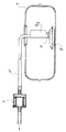
なお、ここで図1はこの発明を適用して構成される燃料用フィルタFの利用状態を理解しやすいように燃料タンクTと燃料ラインP’の一部とを模式的に表しており、図2はかかる燃料タンクT内にある燃料吸い込み口Pに燃料用フィルタFを取り付けた状態を示した構成図であり、また、図3は、かかるフィルタ装置Fを構成するフィルタ主体1の断面構成の一例を、図4は、かかるフィルタ装置Fを構成するフィルタ主体1の断面構成の他の一例を示している。(図3および図4においては、フィルタ主体1の上面側と下面側の断面構成のみを表し、フィルタ主体1内に納められる間隔形成部材3の記載を省略している。)
Here, FIG. 1 schematically shows the fuel tank T and a part of the fuel line P ′ so that the use state of the fuel filter F configured by applying the present invention can be easily understood. 2 is a configuration diagram showing a state in which a fuel filter F is attached to a fuel suction port P in the fuel tank T, and FIG. 3 is a cross-sectional configuration of a filter
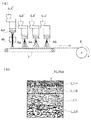
また、図5〜図9はこの発明にかかる燃料用フィルタFを構成する多機能濾材14aとなる不織布の製造過程を理解しやすいようにこれを模式的に表すと共に、(各図の(a)図)、それぞれの製造過程を経て得られる不織布の断面構造を模式的に表している。(各図の(b)図) FIGS. 5 to 9 schematically show the non-woven fabric as the multifunction filter medium 14a constituting the fuel filter F according to the present invention so that the manufacturing process of the nonwoven fabric can be easily understood. Figure) schematically shows a cross-sectional structure of a nonwoven fabric obtained through each manufacturing process. (Figure (b) of each figure)
この実施の形態にかかる燃料用フィルタFは、自動車や二輪自動車などの燃料タンクT内にある燃料吸い込み口Pや、燃料ラインP’中に取り付けられて、内燃機関側に移送される燃料に水や異物を入り込ませないようにするためのものである。 A fuel filter F according to this embodiment is attached to a fuel suction port P in a fuel tank T of a vehicle or a two-wheeled vehicle or a fuel line P ′, and water is transferred to fuel transferred to the internal combustion engine side. It is intended to prevent foreign substances from entering.
典型的には、かかる燃料用フィルタFは、燃料タンクT内に燃料吸い込み口Pを位置させた吸い込みパイプのこの燃料吸い込み口Pに取り付けられる、いわゆるフィルタ(インタンク式燃料フィルタあるいはサクションフィルタなどと称される。)として、あるいはまた、燃料タンクTとインジェクターとの間において燃料ラインP’中に配されるフィルタとして用いられる。(図1) Typically, such a fuel filter F is a so-called filter (such as an in-tank fuel filter or a suction filter) attached to the fuel suction port P of a suction pipe in which the fuel suction port P is located in the fuel tank T. Or as a filter disposed in the fuel line P ′ between the fuel tank T and the injector. (Figure 1)
また、かかる燃料吸い込み口Pを通じた内燃機関側への燃料の移送は、燃料タンクT内に配されるフューエルポンプあるいは燃料タンクT外に配されるフューエルポンプによってなされる。 The fuel is transferred to the internal combustion engine through the fuel suction port P by a fuel pump arranged in the fuel tank T or a fuel pump arranged outside the fuel tank T.
図2は前記サクションフィルタとしての構成例を示している。かかる燃料用フィルタFは、袋状をなすフィルタ主体1を有している。そして、かかる燃料用フィルタFは、この袋状をなすフィルタ主体1の内部空間10を、前記燃料吸い込み口Pに連通させるように、この燃料吸い込み口Pに取り付けられるものとなっている。具体的には、図示の例にあっては、前記燃料用フィルタFが、一端部20を前記燃料吸い込み口Pへの接続端部とすると共に、他端部21を前記フィルタ主体1に形成された連通穴11への接続端部としたプラスチック製の筒状ソケット体2を有しており、この筒状ソケット体2によってフィルタ主体1の内部空間10が燃料吸い込み口Pに連通されるようにしてある。また、この例にあっては、かかる燃料用フィルタFは、前記フィルタ主体1内に納められてこのフィルタ主体1を常時膨らんだ袋状に保つ間隔形成部材3を有している。具体的には、図示の例にあっては、前記間隔形成部材3は、袋状をなすフィルタ主体1の上部の内面にその上面を接しさせると共に、このフィルタ主体1の下部の内面にその下面を接しさせる厚さを持つように構成されており、フィルタ主体1の内部に入れ込まれてこのフィルタ主体1を膨らんだ袋状に常時保つようになっている。この間隔形成部材3には、その上面と下面との間に亘る複数の燃料の通過部(図示は省略する。)が形成されている。また、かかるフィルタ主体1は、二つ以上の濾材14を重ね合わせて構成されている。それと共に、これら二つ以上の濾材14の少なくとも一つは、その開口径を、この濾材14の一次側12と二次側13とで異ならせるように構成されて異なる粒径の塵埃を段階的に捕捉する機能を持った多機能濾材14aとなっている。ここで、本明細書において濾材14の一次側12とは、この濾材14におけるフィルタ主体1の外側に位置される側であってこの濾材14への燃料の流入側(上流側)を意味し、また、濾材14の二次側13とは、この濾材14におけるフィルタ主体1の内側に位置される側であってこの濾材14からの燃料の流出側(下流側)を意味している。
FIG. 2 shows a configuration example as the suction filter. The fuel filter F includes a filter
これにより、かかる燃料用フィルタFによれば、単一のかかる多機能濾材14aによって、粗い塵埃から微細な塵埃までの、粒径の異なる塵埃をこの多機能の濾材14の厚さ方向における異なる箇所においてそれぞれ捕捉することができ、かかる燃料用フィルタFにおける前記フィルタ主体1の目詰まりを生じさせ難い状態で、吸引される燃料から塵埃を適切に除去させることができる。
As a result, according to the fuel filter F, the single multi-functional filter medium 14a allows the dust having different particle diameters from coarse dust to fine dust to be different in the thickness direction of the multi-functional filter medium 14. In the fuel filter F, dust can be appropriately removed from the sucked fuel in a state in which the filter
また、溶着可能な複数のシート状ないしはマット状の濾材14を重ね合わせた後にこれを二つ折りにして折った箇所以外の箇所に線状又は帯状に施した溶着とこの折った箇所とにより燃料用フィルタFの主体となる袋状のフィルタ主体1を成形したり、あるいはまた、このように濾材14を重ね合わせてなる二つの濾材組を、それぞれのフィルタ主体1の内側となる側を対面させるように重ね合わせた状態で、これらに周回状をなす溶着を施して前記袋状のフィルタ主体を成形したりする場合には、溶着箇所の濾材14の積層枚数を最小にして、容易且つ適切にかかる溶着がなされるようにすることができる。
In addition, a plurality of sheet-like or mat-like filter media 14 that can be welded are overlapped and then folded in half, and then welded in a linear or belt-like manner at a place other than the place where it is folded, and the folded part is used for fuel. The bag-shaped filter
また、前記濾材14の平均開口径、すなわち、濾材14における微細な燃料の通過孔の平均孔径を異ならせる二枚以上の濾材14を積層させてこのような溶着によって袋状のフィルタ主体1を成形する場合には、その溶着箇所において濾材14の積層枚数が過大となり、溶着によってこれらを一体化させ難くなる。この実施の形態にかかるフィルタ装置Fにあっては、単一のかかる多機能濾材14aによってこうした溶着・一体化を行いやすい態様で目詰まりを生じがたいフィルタ主体1を構成させることができる。この実施の形態にあっては、かかる多機能濾材14aは不織布として構成されており、この多機能濾材14aにおける開口径は、この多機能濾材14aの二次側13に向かうに連れて漸次小さくなるようにしてある。これにより、この実施の形態にあっては、多機能濾材14aの一次側12において比較的粗い塵埃を、二次側13において比較的微細な塵埃を、その中間ではこれらの間に位置される粒径の塵埃をそれぞれ位置を異ならせて捕捉するようになっている。
Further, two or more filter media 14 having different average opening diameters of the filter media 14, that is, the average pore diameters of the fine fuel passage holes in the filter media 14 are laminated, and the bag-shaped filter
この実施の形態にあっては、かかる多機能濾材14aを、不織布生成の乾式法であるスパンボンド法及びメルトブローン法の双方又はいずれか一方の製法を用いて生成させている。メルトブローン法では極細繊維を紡糸可能であり、多機能濾材14aにおける微細な塵埃を捕捉する密な層を適切に生成させることができる。スパンボンド法では、メルトブローン法に比べると生成される繊維を極細化させ難いが、生成される繊維の強度を高めやすく、また、スパンボンド法は不織布の効率的な生産に適している。 In this embodiment, the multifunctional filter medium 14a is produced by using either or both of the spunbond method and the meltblown method, which are dry methods for producing nonwoven fabrics. In the melt blown method, ultrafine fibers can be spun and a dense layer for capturing fine dust in the multifunctional filter medium 14a can be appropriately generated. In the spunbond method, compared to the meltblown method, it is difficult to make the produced fiber extremely fine, but the strength of the produced fiber is easily increased, and the spunbond method is suitable for the efficient production of the nonwoven fabric.
図5〜図7は、多機能濾材14aを、開口径を異ならせる、つまり、微細な燃料の通過孔の平均孔径を異ならせる二以上の層Lを、前記製法のいずれかによって先行して生成された層Lの上に前記製法のいずれかによって次の層Lを生成させて構成させる例を示している。各図中、符号4は不織布製造装置であり、符号5はコンベヤであり、符号6はこのコンベヤ5により搬送される多機能濾材14aとなる不織布の巻き取り装置であり、符号4bはスパンボンド法による不織布製造装置4”を構成する繊維延伸装置である。
5 to 7 show that the multi-function filter medium 14a is produced in advance by any one of the above-described processes, with two or more layers L having different opening diameters, that is, different average pore diameters of fine fuel passage holes. An example is shown in which the next layer L is generated and configured on any of the above-described manufacturing methods on the formed layer L. In each figure, reference numeral 4 is a non-woven fabric manufacturing apparatus,
具体的には、図5はメルトブローン法による不織布製造装置4’を多段化して、それぞれの不織布製造装置4’によって生成される繊維の太さとノズル4aからの吐出量を異ならせるようにすると共に、コンベヤ5の搬送方向に間隔を開けてこのコンベヤ5上に各不織布製造装置4’のノズル4aを配させ、このコンベヤ5の搬送手前側に位置される先順位のノズル4aによってコンベヤ5上に生成された前記層L上に、次順位のノズル4aによって前記次の層Lを生成させて、多機能濾材14aとなる不織布を生成させている。このように生成された多機能濾材14aとなる不織布は、細い繊維から構成される密な層Laと、太い繊維から構成される粗い層Lcと、この両層La、Lcの間に中間の太さの繊維から構成される粗密も両層La、Lcの中間となる中間層Lbを一体に備える。(図5(b)図)この場合、多段化されたそれぞれの不織布製造装置4’によって生成される繊維の太さを変えずにノズル4aからの吐出量を異ならせるようにすることによっても、密な層Laと、粗い層Lcと、この両層La、Lcの間に粗密を両層La、Lcの中間とする中間層Lbと一体に備えた多機能濾材14aとなる不織布を生成することができる。
Specifically, FIG. 5 is a multi-stage nonwoven fabric manufacturing apparatus 4 ′ by the melt blown method so that the fiber thickness generated by each nonwoven fabric manufacturing apparatus 4 ′ is different from the discharge amount from the
また、図6はスパンボンド法による不織布製造装置4”を多段化して、それぞれの不織布製造装置4”によって生成される繊維の太さとノズル4aからの吐出量を異ならせるようにすると共に、コンベヤ5の搬送方向に間隔を開けてこのコンベヤ5上に各不織布製造装置のノズル4aを配させ、このコンベヤ5の搬送手前側に位置される先順位のノズル4aによってコンベヤ5上に生成された前記層L上に、次順位のノズル4aによって前記次の層Lを生成させて、多機能濾材14aとなる不織布を生成させている。このように生成された多機能濾材14aとなる不織布も、細い繊維から構成される密な層Laと、太い繊維から構成される粗い層Lcと、この両層La、Lcの間に中間の太さの繊維から構成される粗密も両層La、Lcの中間となる中間層Lbを一体に備える。(図6(b)図)この場合にも、多段化されたそれぞれの不織布製造装置4”によって生成される繊維の太さを変えずにノズル4aからの吐出量を異ならせるようにすることによっても、密な層Laと、粗い層Lcと、この両層La、Lcの間に粗密を両層La、Lcの中間とする中間層Lbと一体に備えた多機能濾材14aとなる不織布を生成することができる。
FIG. 6 shows a multi-stage nonwoven fabric manufacturing apparatus 4 ″ by the spunbond method, in which the thickness of the fiber produced by each nonwoven fabric manufacturing apparatus 4 ″ and the discharge amount from the
また、図7は前記のように多段化されたメルトブローン法による不織布製造装置4’にスパンボンド法による不織布製造装置4”をさらに組み合わせると共に、コンベヤ5の搬送方向に間隔を開けてこのコンベヤ5上に各不織布製造装置4のノズル4aを配させ、このコンベヤ5の搬送手前側に位置される先順位のノズル4aによってコンベヤ5上に生成された前記層L上に、次順位のノズル4aによって前記次の層Lを生成させて、多機能濾材14aとなる不織布を生成させている。この例では、スパンボンド法による不織布製造装置4”によって最も太い繊維からなる最も粗い層Ldを最初に生成させるようにしている。(図7(a)図)このように生成された多機能濾材14aとなる不織布は、細い繊維から構成される密な層Laと、太い繊維から構成される粗い層Lcと、この両層La、Lcの間に中間の太さの繊維から構成される粗密も両層La、Lcの中間となる中間層Lbを一体に備えると共に、この粗い層Lcの外側に前記スパンボンド法による最も粗い層Ldを備える。(図7(b)図)
Further, FIG. 7 shows a combination of the non-woven fabric manufacturing apparatus 4 ′ based on the melt blown method and the non-woven fabric manufacturing apparatus 4 ″ based on the spun bond method as described above, and an interval in the conveying direction of the
一方、図8および図9は、多機能濾材14aを、この多機能濾材14aの厚さ方向において流路の断面積が徐々に変化するように、前記製法の紡糸条件を経時的に変化させることによって生成させて構成させる例を示している。各図中、符号4は不織布製造装置であり、符号5はコンベヤであり、符号6はこのコンベヤ5により搬送される多機能濾材14aとなる不織布の巻き取り装置であり、符号4bはスパンボンド法による不織布製造装置4”を構成する繊維延伸装置である。
On the other hand, FIG. 8 and FIG. 9 show that the spinning condition of the production method is changed over time so that the cross-sectional area of the flow path gradually changes in the multifunction filter medium 14a in the thickness direction of the multifunction filter medium 14a. It shows an example of generating and configuring by. In each figure, reference numeral 4 is a non-woven fabric manufacturing apparatus,
具体的には、この図8および図9に示される例では、メルトブローン法又はスパンボンド法による不織布製造装置4’(4”)によって生成される繊維の太さとノズル4aからの吐出量を経時的に変化させながらコンベヤ5上に一定面積の多機能濾材14aとなる不織布を生成させている。一定面積のかかる不織布の生成が終了した段階でコンベヤ5を走行させこのように生成された不織布に連続する次の一定面積の不織布を同様に紡糸条件を経時的に変化させながら生成させる。このように生成された多機能濾材14aとなる不織布は、その一面側から他面側に向かうに連れて繊維の太さを徐々に変化させながら次第に粗となるように、または次第に密となるように構成される。(図8(b)図、図9(b)図)この場合にも、不織布製造装置4’(4”)によって生成される繊維の太さを変えずにノズル4aからの吐出量を経時的に変化させることによっても、一面側から他面側に向かうに連れて繊維の太さを徐々に変化させながら次第に粗となるように、または次第に密となるように構成された多機能濾材14aとなる不織布を生成することができる。
Specifically, in the example shown in FIGS. 8 and 9, the thickness of the fiber generated by the nonwoven fabric manufacturing apparatus 4 ′ (4 ″) by the melt blown method or the spun bond method and the discharge amount from the
このようにすることで、スムースな密度勾配を持った不織布の濾材14、すなわち多機能濾材14aを比較的低廉に得ることができ、これにより濾過精度の高く目詰まりし難い燃料用フィルタFを低廉に供給することができる。 By doing so, it is possible to obtain a non-woven filter medium 14 having a smooth density gradient, that is, a multi-function filter medium 14a at a relatively low cost, thereby reducing the filter F for fuel that has high filtration accuracy and is difficult to clog. Can be supplied to.
より具体的には、かかる多機能濾材14aを構成する不織布は、前記密な層Laと中間層Lbと粗い層Lcとを一体に備えてなる場合には、各層La、Lb、Lcを以下のよう構成させることが、濾過精度を向上させると共に多機能濾材14aの目詰まりをし難くしてそれをロングライフ化させる観点から最適である。なお、下記の平均開口径は、米国ポーラスマテリアルズ社 (Porous Materials Inc.)製の自動細孔径分布測定器パームポロメーター(PERM POROMETER)により測定した。
密な層La:平均開口径 2μm〜20μm
目付け 5g/m2〜40g/m2
繊維径 0.4μm〜5μm
中間層Lb:平均開口径 10μm〜60μm
目付け 10g/m2〜100g/m2
繊維径 1μm〜20μm
粗い層Lc:平均開口径 20μm〜100μm
目付け 10g/m2〜100g/m2
繊維径 10μm〜40μm
More specifically, when the nonwoven fabric constituting the multi-functional filter medium 14a is integrally provided with the dense layer La, the intermediate layer Lb, and the coarse layer Lc, the layers La, Lb, and Lc are formed as follows. Such a configuration is optimal from the viewpoint of improving the filtration accuracy and making it difficult to clog the multifunctional filter medium 14a, thereby extending the life. In addition, the following average opening diameter was measured with the automatic pore diameter distribution measuring device palm porometer (PERM POROMETER) by the United States Porous Materials Inc. (Porous Materials Inc.).
Dense layer La:
Weight per unit area 5 g / m 2 to 40 g / m 2
Fiber diameter 0.4 μm to 5 μm
Intermediate layer Lb:
Fabric weight 10g / m 2 to 100g / m 2
Fiber diameter 1μm ~ 20μm
Coarse layer Lc:
Fabric weight 10g / m 2 to 100g / m 2
また、かかる多機能濾材14aを構成する不織布は、以下の材料によって構成させることが最適である。
ポリオレフィン(耐薬品性が高く、低廉、加水分解し難い)
ポリエステル(耐薬品性、耐熱性が高い)
ポリアミド(耐薬品性、耐熱性が高い)
ポリフェニレンサルファイド(耐薬品性、耐熱性が非常に高い)
ポリアセタール(耐薬品性が高い)
Moreover, it is optimal that the nonwoven fabric constituting the multifunctional filter medium 14a is composed of the following materials.
Polyolefin (high chemical resistance, low cost, difficult to hydrolyze)
Polyester (high chemical and heat resistance)
Polyamide (high chemical and heat resistance)
Polyphenylene sulfide (Chemical resistance and heat resistance are very high)
Polyacetal (high chemical resistance)
また、図4に示されるフィルタ主体1の構成例では、多機能濾材14aの二次側13に、メルトブローン法によって生成され、且つ多機能濾材14aの平均開口径よりも平均開口径を小さくさせた濾材14bが重ねられている。
Further, in the configuration example of the filter
これにより、この図4に示される例では、平均開口径を小さくさせやすいメルトブローン法による不織布の濾材14bをメインフィルタとして、そして前記多機能濾材14aをプレフィルタとして、このメインフィルタの負担を最小にさせた状態でロングライフのフィルタ装置を構成させることができる。 Thus, in the example shown in FIG. 4, the non-woven filter medium 14b by the melt-blown method that easily reduces the average opening diameter is used as a main filter, and the multifunction filter medium 14a is used as a pre-filter to minimize the burden on the main filter. In this state, a long life filter device can be configured.
また、この図4に示される例では、フィルタ主体1の最も内側に位置される濾材14が、スパンボンド法により形成された濾材14cとしてある。
In the example shown in FIG. 4, the filter medium 14 located on the innermost side of the filter
このようにした場合、かかるスパンボンド法により形成された濾材14cによってフィルタ主体1に剛性(こわさ)を付与してフィルタ主体1を保形し易くできる。また、前記間隔形成部材3に、メルトブローン法によって形成された濾材14を接しさせずに、これより剛性の高いスパンボンド法によって形成された濾材14cが接するようにすることができる。
In this case, the filter
また、この図4に示される例では、フィルタ主体1の最も外側に位置される濾材14が、織物メッシュ14dとしてある。このようにした場合、燃料タンクTの内圧の変化などによってこの燃料タンクTの下部内壁面Taが内外に移動することなどに伴なって(つまり、燃料タンクTの膨縮などに伴って)フィルタ主体1の下面部とこの燃料タンクTの下部内壁面Taとの間に擦れが生じても、不織布からなる多機能濾材14aがその影響を直接受けることがないようすることができる。
Further, in the example shown in FIG. 4, the filter medium 14 positioned on the outermost side of the filter
かかる織物メッシュ14dは、典型的には、ポリオレフィン、ポリエステル、ポリアミド、ポリフェニレンサルファイド、ポリアセタールなどの合成繊維を油水分離に十分な細かさの網目を持つように織り込むことによって構成される。かかる織物メッシュ14dは、例えば、畳織、平織、あや織、朱子織などによって構成することができる。 The woven mesh 14d is typically configured by weaving synthetic fibers such as polyolefin, polyester, polyamide, polyphenylene sulfide, polyacetal, etc., so as to have a fine enough mesh for oil-water separation. Such a woven mesh 14d can be formed of, for example, a tatami mat, a plain weave, a twill weave, a satin weave, or the like.
フィルタ主体1を構成する各濾材14を同一の合成樹脂材料によって構成しておくこともできる。例えば、かかる各層をいずれもポリオレフィン、ポリエステル、ポリアミド、ポリフェニレンサルファイド又はポリアセタールによって構成する。
Each filter medium 14 constituting the filter
このようにした場合、重ね合わせた各濾材14相互を溶着によって馴染み良く一体化させて袋状をなすフィルタ主体1を構成させることができる。
In this case, it is possible to configure the filter
すなわち、図4に示される例では、フィルタ主体1の最外層を織物メッシュ14dとし、最内層をスパンボンド法によって形成された濾材14cとすると共に、両者の間の織物メッシュ14d側にプレフィルタ(多機能濾材14a)を両者の間のスパンボンド法によって形成された濾材14c側にメインフィルタ(メルトブローン法によって形成された濾材14b)を位置させるようにしてこのメインフィルタとプレフィルタを挟み込んでフィルタ主体1を構成させている。一方、図3に示される例では、フィルタ主体1の最外層を織物メッシュ14dとし、最内層をスパンボンド法によって形成された濾材14cとすると共に、両者の間に多機能濾材14aを位置させるようにしてフィルタ主体1を構成させている。
That is, in the example shown in FIG. 4, the outermost layer of the filter
図示の例にかかるフィルタ主体1は、このように濾材14を重ね合わされた状態からスパンボンド法によって形成された濾材14cを内方に位置させるようにして、かつ、前記間隔形成部材3を挟み込ませた状態で二つ折りにし、この後、折った辺部を除く辺部に亘って、あるいは、この折った辺部を除く辺部に沿ってこの辺部よりも内方に、二つ折りにされて重ね合わされた一方の側と他方の側とを一体化させる熱シール部(溶着箇所15)を形成させることにより、構成することができる。前記筒状ソケット体2への連通穴11は、かかる二つ折りを施すに先立って、前記のように重ね合わせた四枚の濾材14に予め穿設させておく。
The filter
あるいはまた、図示の例にかかるフィルタ主体1は、三枚(図3の態様)又は四枚(図4の態様)の濾材14を重ね合わせてなる第一の濾材14組と、前記のように四枚の濾材14を重ね合わせてなる第二の濾材14組とを、第一の濾材14組のスパンボンド法によって形成された濾材14cと、第二の濾材14組のスパンボンド法によって形成された濾材14cとが向き合わされるようにして、かつ、両者の間に前記間隔形成部材3を挟み込ませた状態で重ね合わせ、この後、挟み込まれた間隔形成部材3の外郭を巡るように第一の濾材14組と第二の濾材14組とを一体化させる熱シール部を形成させることにより、構成することができる。前記筒状ソケット体2への連通穴11は、事前に第一の濾材14組又は第二の濾材14組に、穿設させておく。
Alternatively, the filter
このように形成されるフィルタ主体1にはさらに、その形成に先だってフィルタ主体1を構成する各濾材14を前記熱シール部以外で一体化させるようにスポット的な溶着を適宜施すようにすることもある。
Prior to the formation of the filter
また、前記熱シール部15よりも外方に位置される不要箇所は、必要に応じてカッティングして、フィルタ主体1の形状を整えるようにする。
Further, unnecessary portions located outside the
F 燃料用フィルタ
T 燃料タンク
12 一次側
13 二次側
14 濾材
14a 多機能濾材
F Fuel filter
Claims (3)
この燃料用フィルタを構成する濾材の少なくとも一つを、この濾材における開口径を、この濾材の一次側と二次側とで異ならせると共にこの二次側に向かうに連れて小さくするようにして、異なる粒径の塵埃を段階的に捕捉する機能を持った多機能濾材としていることを特徴とする燃料用フィルタ。 A fuel filter provided in a fuel suction port and a fuel line in a fuel tank and used for fuel filtration,
At least one of the filter media constituting the fuel filter, the opening diameter of the filter media is made different on the primary side and the secondary side of the filter media and is made smaller toward the secondary side, A fuel filter characterized by being a multi-functional filter medium having a function of capturing dusts of different particle sizes step by step.
開口径を異ならせる二以上の層を、前記製法のいずれかによって先行して生成された層の上に前記製法のいずれかによって次の層を生成させてなることを特徴とする請求項1記載の燃料用フィルタ。 The multi-functional filter medium is produced by the spunbond method and / or meltblown method, and
The two or more layers having different opening diameters are produced by forming the next layer by any of the above-mentioned production methods on the layer previously produced by any of the above-mentioned production methods. Fuel filter.
多機能濾材の厚さ方向においてその開口径が徐々に変化するように、前記製法の紡糸条件を経時的に変化させることによって生成させてなることを特徴とする請求項1記載の燃料用フィルタ。 The multifunctional filter medium is produced by one of the spunbond method and the melt blown method,
2. The fuel filter according to claim 1, wherein the filter is produced by changing the spinning conditions of the manufacturing method with time so that the opening diameter of the multifunctional filter material gradually changes in the thickness direction.
Priority Applications (7)
| Application Number | Priority Date | Filing Date | Title |
|---|---|---|---|
| JP2008179816A JP2010019151A (en) | 2008-07-10 | 2008-07-10 | Fuel filter |
| TW098122749A TWI484093B (en) | 2008-07-10 | 2009-07-06 | Fuel filter |
| CN2009801263069A CN102084116B (en) | 2008-07-10 | 2009-07-09 | Fuel filter |
| EP09794504A EP2320060A4 (en) | 2008-07-10 | 2009-07-09 | Fuel filter |
| US12/737,374 US8173013B2 (en) | 2008-07-10 | 2009-07-09 | Fuel filter |
| PCT/JP2009/062554 WO2010005060A1 (en) | 2008-07-10 | 2009-07-09 | Fuel filter |
| KR1020107029872A KR20110011721A (en) | 2008-07-10 | 2009-07-09 | Fuel filter |
Applications Claiming Priority (1)
| Application Number | Priority Date | Filing Date | Title |
|---|---|---|---|
| JP2008179816A JP2010019151A (en) | 2008-07-10 | 2008-07-10 | Fuel filter |
Publications (1)
| Publication Number | Publication Date |
|---|---|
| JP2010019151A true JP2010019151A (en) | 2010-01-28 |
Family
ID=41507170
Family Applications (1)
| Application Number | Title | Priority Date | Filing Date |
|---|---|---|---|
| JP2008179816A Pending JP2010019151A (en) | 2008-07-10 | 2008-07-10 | Fuel filter |
Country Status (7)
| Country | Link |
|---|---|
| US (1) | US8173013B2 (en) |
| EP (1) | EP2320060A4 (en) |
| JP (1) | JP2010019151A (en) |
| KR (1) | KR20110011721A (en) |
| CN (1) | CN102084116B (en) |
| TW (1) | TWI484093B (en) |
| WO (1) | WO2010005060A1 (en) |
Cited By (9)
| Publication number | Priority date | Publication date | Assignee | Title |
|---|---|---|---|---|
| KR101091049B1 (en) | 2011-06-17 | 2011-12-08 | 주식회사 케이엠에프 | A fuel filter for fuel pump of automobile and method for preparing the same |
| JP2013519825A (en) * | 2010-02-12 | 2013-05-30 | ドナルドソン カンパニー,インコーポレイティド | Liquid filter media |
| KR20170043584A (en) * | 2014-08-14 | 2017-04-21 | 이베에스 필트란 쿤스츠토프-/메탈러조이그니세 게엠베하 | Oil filter unit |
| JP2018015702A (en) * | 2016-07-27 | 2018-02-01 | 旭化成株式会社 | Filter material for fuel for automobile |
| JP2018536530A (en) * | 2015-10-21 | 2018-12-13 | エスドゥブルヴェエム・ルクセンブルク・エス・アー・エール・エルSwm Luxembourg Sarl | Fuel filter using one or more wet synthetic fiber layers |
| WO2019194244A1 (en) * | 2018-04-06 | 2019-10-10 | 旭化成株式会社 | Filter medium |
| JP2021003704A (en) * | 2020-09-30 | 2021-01-14 | 旭化成株式会社 | Filter material for fuel for automobile |
| JP2022087132A (en) * | 2014-12-01 | 2022-06-09 | 愛三工業株式会社 | Fuel filter |
| WO2023013660A1 (en) * | 2021-06-15 | 2023-02-09 | 信越化学工業株式会社 | Exposure pellicle facilitating atomspheric pressure adjustment |
Families Citing this family (28)
| Publication number | Priority date | Publication date | Assignee | Title |
|---|---|---|---|---|
| JP5336045B2 (en) * | 2007-01-10 | 2013-11-06 | 株式会社ニフコ | Fuel filter device |
| US7976712B2 (en) * | 2007-10-01 | 2011-07-12 | Cummins Filtration Ip, Inc. | Apparatus, system, and method for filtration of a dosing fluid in an exhaust aftertreatment system |
| DE102008027662A1 (en) * | 2008-06-10 | 2009-12-17 | Ibs Filtran Kunststoff- / Metallerzeugnisse Gmbh | Oil pan with oil filter |
| JP2010019151A (en) * | 2008-07-10 | 2010-01-28 | Nifco Inc | Fuel filter |
| DE102008038958B4 (en) * | 2008-08-13 | 2017-11-02 | Ibs Filtran Kunststoff-/ Metallerzeugnisse Gmbh | Oil pan with oil filter to carrier unit |
| JP5571366B2 (en) * | 2009-12-04 | 2014-08-13 | 愛三工業株式会社 | Filter device |
| JP5875768B2 (en) * | 2010-06-25 | 2016-03-02 | 本田技研工業株式会社 | Fuel filtration device |
| IT1401966B1 (en) * | 2010-09-24 | 2013-08-28 | Gvs Spa | IMPROVED FILTERING DEVICE FOR A VEHICLE FUEL PUMP. |
| US8580111B2 (en) * | 2010-11-29 | 2013-11-12 | Toyota Jidosha Kabushiki Kaisha | Device for separating fuel components |
| CN103635243B (en) * | 2011-03-29 | 2016-06-08 | 酷思滤清系统有限公司 | There is fluid filter in the case of plastic holder |
| US9238953B2 (en) | 2011-11-08 | 2016-01-19 | Schlumberger Technology Corporation | Completion method for stimulation of multiple intervals |
| US20130146517A1 (en) * | 2011-12-13 | 2013-06-13 | GM Global Technology Operations LLC | Filtering assembly having sediment trap |
| US8372278B1 (en) * | 2012-03-21 | 2013-02-12 | GM Global Technology Operations LLC | Liquid fuel strainer assembly |
| US9650851B2 (en) | 2012-06-18 | 2017-05-16 | Schlumberger Technology Corporation | Autonomous untethered well object |
| US9416758B2 (en) | 2012-12-21 | 2016-08-16 | Ford Global Technologies, Llc | Fuel filter |
| US9486725B2 (en) * | 2013-02-21 | 2016-11-08 | Caterpillar Inc. | System and method for filtering fuel within fuel tank |
| US10086688B2 (en) * | 2013-02-28 | 2018-10-02 | Gvs Filtration Inc. | In-tank suction filter as the reserve cavity for a fluid delivery module assembly |
| US9470193B2 (en) * | 2013-03-22 | 2016-10-18 | Caterpillar Inc. | System and method for filtering fuel within fuel tank |
| KR101340914B1 (en) * | 2013-05-23 | 2013-12-13 | 주식회사 코아비스 | Strainer and fuel pump module having the same |
| US20150053627A1 (en) * | 2013-08-26 | 2015-02-26 | Hollingsworth & Vose Company | Filter media having an optimized gradient |
| JP6301236B2 (en) * | 2014-11-07 | 2018-03-28 | 愛三工業株式会社 | Fuel filter device |
| JP2016160890A (en) * | 2015-03-04 | 2016-09-05 | 愛三工業株式会社 | Fuel supply system |
| US10328366B2 (en) * | 2015-05-21 | 2019-06-25 | Caterpillar Inc. | Fluid reservoir having inlet filtering |
| JP6265200B2 (en) * | 2015-07-29 | 2018-01-24 | 株式会社デンソー | Suction filter and fuel supply device |
| JP6380364B2 (en) * | 2015-12-17 | 2018-08-29 | 株式会社デンソー | Fuel pump and fuel pump module |
| DE102018208643A1 (en) * | 2018-05-30 | 2019-12-05 | Röchling Automotive SE & Co. KG | Car tank assembly and removal module with a porous conveyor body |
| DE102019202136A1 (en) * | 2019-02-18 | 2020-08-20 | Siemens Mobility GmbH | Arrangement for filtering liquids |
| KR102178858B1 (en) * | 2019-09-25 | 2020-11-13 | 주식회사 코아비스 | Strainer of fuel pump |
Citations (6)
| Publication number | Priority date | Publication date | Assignee | Title |
|---|---|---|---|---|
| JPH03175141A (en) * | 1989-12-04 | 1991-07-30 | Aisan Ind Co Ltd | Fuel filter for internal combustion engine |
| JPH0596110A (en) * | 1991-03-15 | 1993-04-20 | Chisso Corp | Cylindrical filter and its production |
| JPH06142417A (en) * | 1992-11-06 | 1994-05-24 | Roki Techno:Kk | Pleat type filter cartridge |
| JPH08100371A (en) * | 1994-09-28 | 1996-04-16 | Toray Ind Inc | Base material for filter and its production |
| JP2003260321A (en) * | 2001-12-27 | 2003-09-16 | Toray Ind Inc | Air filter |
| JP2005048721A (en) * | 2003-07-31 | 2005-02-24 | Nifco Inc | Filter device for fuel |
Family Cites Families (131)
| Publication number | Priority date | Publication date | Assignee | Title |
|---|---|---|---|---|
| US1394011A (en) * | 1917-09-04 | 1921-10-18 | Henry A Hills | Filter for gasolene-tanks |
| US1518686A (en) * | 1922-11-16 | 1924-12-09 | John E Bland | Gasoline tank |
| US1568796A (en) * | 1925-03-09 | 1926-01-05 | Chrysler Corp | Oil filter |
| US1773134A (en) * | 1927-10-31 | 1930-08-19 | Willys Overland Co | Engine-oil strainer |
| US2057779A (en) * | 1933-11-28 | 1936-10-20 | Edwin F Jacobs | Gasoline purifying means |
| US2261915A (en) * | 1939-08-23 | 1941-11-04 | Carter Carburetor Corp | Electric fuel pump |
| US2711828A (en) * | 1949-09-30 | 1955-06-28 | Chrysler Corp | Plastic fabric filter |
| US2767736A (en) * | 1953-03-25 | 1956-10-23 | Frank P Lackinger | Fluid pickup |
| US2788125A (en) * | 1953-07-31 | 1957-04-09 | Edmond F Webb | Fuel filter |
| US2810482A (en) * | 1954-03-08 | 1957-10-22 | Bendix Aviat Corp | Immersion fuel tank filter |
| US2770362A (en) * | 1954-06-25 | 1956-11-13 | Patrick J Paquin | Fuel tank sediment trap |
| US2937755A (en) * | 1954-09-13 | 1960-05-24 | Acf Ind Inc | Filter for electric fuel pump |
| US2923411A (en) * | 1956-03-14 | 1960-02-02 | Ford Motor Co | Fuel filter |
| US2877903A (en) * | 1956-11-29 | 1959-03-17 | Arrow Tools Inc | Filter unit |
| US2933188A (en) * | 1957-01-29 | 1960-04-19 | John P Jacula | Filters |
| US2905327A (en) * | 1958-04-03 | 1959-09-22 | Tillotson Mfg Co | Fuel filter |
| US3020950A (en) * | 1958-11-19 | 1962-02-13 | Daimler Benz Ag | Fuel tank construction, especially for motor vehicles |
| US3061104A (en) * | 1959-08-17 | 1962-10-30 | John F Schaffner | Fuel tank outlet shield |
| US3108065A (en) * | 1959-09-29 | 1963-10-22 | Gen Motors Corp | Fuel tank strainer |
| US3023905A (en) * | 1959-10-23 | 1962-03-06 | Gen Motors Corp | Combined strainer and fuel tank "empty" signaling device |
| US3171806A (en) * | 1960-07-15 | 1965-03-02 | John F Schaffner | Fuel filter |
| US3295297A (en) * | 1965-10-19 | 1967-01-03 | Cobe Lab | Filter and bubble trap |
| US3480149A (en) * | 1967-03-08 | 1969-11-25 | Gen Motors Corp | Flat casing filter device |
| US3731805A (en) * | 1971-08-13 | 1973-05-08 | Gen Motors Corp | One-tank safety fuel reserve |
| JPS5555784Y2 (en) * | 1972-10-04 | 1980-12-24 | ||
| US3826372A (en) * | 1973-06-14 | 1974-07-30 | Kuss R & Co Inc | Flexible filter |
| US3875059A (en) * | 1973-12-10 | 1975-04-01 | Gen Motors Corp | Electric fuel pump strainer stand-off |
| US3900397A (en) * | 1974-06-10 | 1975-08-19 | Kuss & Co R L | Fuel tank filter |
| US4312753A (en) * | 1980-01-17 | 1982-01-26 | Bell Steven L | Intank fuel filter |
| US4304664A (en) * | 1980-05-05 | 1981-12-08 | General Motors Corporation | Fuel strainer assembly |
| JPS57184408A (en) * | 1981-05-08 | 1982-11-13 | Jidosha Denki Kogyo Co Ltd | Filter for fuel tank |
| JPH0244805Y2 (en) * | 1986-01-17 | 1990-11-28 | ||
| JPH0773643B2 (en) * | 1986-01-17 | 1995-08-09 | 株式会社ニフコ | Fuel tank filter |
| US4714647A (en) | 1986-05-02 | 1987-12-22 | Kimberly-Clark Corporation | Melt-blown material with depth fiber size gradient |
| JPH0529134Y2 (en) * | 1986-08-01 | 1993-07-27 | ||
| JPH064888Y2 (en) * | 1987-05-15 | 1994-02-09 | 株式会社ニフコ | filter |
| JPH0723569Y2 (en) * | 1987-08-06 | 1995-05-31 | 日産自動車株式会社 | Fuel tank filter |
| JPH0617032Y2 (en) * | 1987-11-18 | 1994-05-02 | 三菱電機株式会社 | In-tank fuel pump |
| US4828694A (en) * | 1988-01-11 | 1989-05-09 | Filtertek, Inc. | Filter with filtration envelope spacing means |
| US5055187A (en) * | 1988-05-27 | 1991-10-08 | Kyosan Denki Kabushiki Kaisha | Fuel filter incorporated in a fuel tank |
| JPH02222705A (en) * | 1989-02-22 | 1990-09-05 | Mitsubishi Electric Corp | Fuel filter |
| US5169531A (en) * | 1989-02-22 | 1992-12-08 | Mitsubishi Denki Kabushiki Kaisha | Noise diffusing fuel filter |
| JP2554565Y2 (en) * | 1990-05-30 | 1997-11-17 | 愛三工業株式会社 | Filter for in-tank pump |
| US5049271A (en) * | 1990-08-27 | 1991-09-17 | Filtertek, Inc. | Fuel tank filter |
| JP3106252B2 (en) * | 1991-02-18 | 2000-11-06 | 株式会社ニフコ | Vehicle fuel tank device |
| JP2536541Y2 (en) * | 1991-12-27 | 1997-05-21 | 株式会社ニフコ | Filter for in-tank pump of automobile fuel tank |
| US5186152A (en) * | 1992-02-10 | 1993-02-16 | General Motors Corporation | Automotive fuel system |
| JP2684491B2 (en) * | 1992-06-12 | 1997-12-03 | 京三電機株式会社 | In-tank fuel filter |
| US5607578A (en) * | 1993-05-06 | 1997-03-04 | Aisan Kogyo Kabushiki Kaisha | Filter system for an in-tank fuel pump |
| US5312545A (en) * | 1993-05-07 | 1994-05-17 | Starin Ronald H | Fuel filtering device |
| JPH0796112A (en) * | 1993-06-24 | 1995-04-11 | Kiyousan Denki Kk | In-tank type fuel filter for automobile |
| JP3353986B2 (en) * | 1993-10-04 | 2002-12-09 | 株式会社ニフコ | Fuel filter |
| US5584988A (en) * | 1993-11-11 | 1996-12-17 | Nissan Motor Co., Ltd. | Filter for in-tank fuel pump |
| US6169045B1 (en) * | 1993-11-16 | 2001-01-02 | Kimberly-Clark Worldwide, Inc. | Nonwoven filter media |
| US5415146A (en) * | 1993-12-14 | 1995-05-16 | Walbro Corporation | Supplemental in-tank filter |
| JP2925907B2 (en) * | 1993-12-27 | 1999-07-28 | 本田技研工業株式会社 | Filter device |
| JP3068743B2 (en) * | 1994-03-24 | 2000-07-24 | 本田技研工業株式会社 | Filter device |
| US5647328A (en) * | 1995-06-30 | 1997-07-15 | Walbro Corporation | In-tank fuel pump and reservoir |
| US5665229A (en) * | 1995-07-07 | 1997-09-09 | Kuss Corporation | In-tank fuel filter with floating mounting |
| US5702237A (en) * | 1995-11-03 | 1997-12-30 | Walbro Corporation | In tank fuel pump filter |
| JP3362594B2 (en) * | 1996-02-29 | 2003-01-07 | トヨタ自動車株式会社 | Automotive fuel storage device |
| US5679042A (en) | 1996-04-25 | 1997-10-21 | Kimberly-Clark Worldwide, Inc. | Nonwoven fabric having a pore size gradient and method of making same |
| DE29609750U1 (en) * | 1996-06-04 | 1996-11-28 | Filtertek Sa | Fuel filter |
| DE19626212C2 (en) * | 1996-06-29 | 1998-04-23 | Luk Fahrzeug Hydraulik | Oil suction filter |
| US5716522A (en) * | 1996-10-25 | 1998-02-10 | Kuss Corporation | Non-woven depth media in-tank fuel filter |
| US5776341A (en) * | 1996-12-23 | 1998-07-07 | Sikorsky Aircraft Corporation | Fuel intake device for fuel systems |
| US5924445A (en) * | 1997-02-20 | 1999-07-20 | Sikorsky Aircraft Corporation | Fuel intake device for fuel systems |
| US5795468A (en) * | 1997-03-31 | 1998-08-18 | Ford Motor Company | In-tank automotive fuel filter |
| US5902480A (en) * | 1997-05-13 | 1999-05-11 | Kuss Corporation | Depth media in-tank fuel filter with extruded mesh shell |
| US6293420B1 (en) * | 1997-07-25 | 2001-09-25 | Kautex Textron Gmbh & Co., Kg. | Fuel tank |
| JP3802682B2 (en) * | 1998-06-17 | 2006-07-26 | 株式会社ニフコ | Fuel filter |
| EP1008745B1 (en) * | 1998-06-30 | 2002-10-30 | Mitsubishi Denki Kabushiki Kaisha | Vehicle fuel supplying apparatus |
| US6220454B1 (en) * | 1998-06-30 | 2001-04-24 | Kuss Corporation | Compact in-tank fuel filter |
| WO2000001941A1 (en) * | 1998-07-02 | 2000-01-13 | Mitsubishi Denki Kabushiki Kaisha | Vehicle fuel supplying apparatus |
| DE29812483U1 (en) * | 1998-07-16 | 1998-10-01 | Filtertek Sa | Filters for liquids |
| CA2303659C (en) * | 1999-04-05 | 2004-09-14 | Filtertek Inc. | Filter manufacturing process using a combined welding and cutting step |
| DE19956368C2 (en) * | 1999-11-24 | 2002-01-03 | Sandler C H Gmbh | Process for the production of meltblown nonwovens, meltblown nonwovens produced therefrom and use of the meltblown nonwovens |
| US6343589B1 (en) * | 2000-02-01 | 2002-02-05 | Walbro Corporation | Fuel system with jet pump switching regulator |
| JP2002066216A (en) * | 2000-08-25 | 2002-03-05 | Nifco Inc | Filter device |
| US6471072B1 (en) * | 2000-09-22 | 2002-10-29 | Kuss Corporation | Filter with pump retaining feature |
| US6936554B1 (en) * | 2000-11-28 | 2005-08-30 | Kimberly-Clark Worldwide, Inc. | Nonwoven fabric laminate with meltblown web having a gradient fiber size structure |
| DE50111166D1 (en) * | 2000-12-08 | 2006-11-16 | Ibs Filtran Kunststoff Metall | METAL OIL PAN WITH INTEGRATED OIL FILTER |
| DE20102217U1 (en) * | 2001-02-08 | 2001-06-13 | Filtertek Sa | Filters for liquids, especially fuels |
| DE60220733T2 (en) * | 2001-03-02 | 2007-10-18 | Filtertek, Inc., Hebron | Oil pan filter with filter cartridge |
| US20030010692A1 (en) * | 2001-07-16 | 2003-01-16 | Hiroji Sato | Fuel-filtering device |
| US7478729B2 (en) * | 2001-07-16 | 2009-01-20 | Nifco Inc. | Fuel-filtering device |
| US6638423B2 (en) * | 2001-09-06 | 2003-10-28 | Delphi Technologies, Inc. | Multiple stage fuel strainer assembly |
| JP3956110B2 (en) * | 2001-09-26 | 2007-08-08 | 株式会社ニフコ | suction filter |
| US6613227B2 (en) * | 2002-01-11 | 2003-09-02 | Kuss Corporation | Electrically conductive in-tank fuel filter |
| JP4233815B2 (en) * | 2002-06-19 | 2009-03-04 | 株式会社ミクニ | Fuel pump with filter and fuel filter |
| US7407057B2 (en) * | 2002-09-19 | 2008-08-05 | Mann & Hummel Gmbh | Plastic transmission filter |
| US6833070B2 (en) * | 2003-01-06 | 2004-12-21 | Delphi Technologies, Inc. | Fuel strainer assembly |
| JP2004218607A (en) * | 2003-01-17 | 2004-08-05 | Nifco Inc | Filter device for fuel |
| US6830687B2 (en) * | 2003-01-21 | 2004-12-14 | Delphi Technologies, Inc. | Fuel strainer assembly |
| US7112278B2 (en) * | 2003-01-21 | 2006-09-26 | Denso Corporation | Fuel filter having double layer structure |
| US6953527B2 (en) * | 2003-02-17 | 2005-10-11 | Tecumseh Products Company | Fuel tank with water trap |
| US7087160B2 (en) * | 2003-05-29 | 2006-08-08 | Spx Corporation | Outside-in flow engine and transmission filter and method |
| US6821422B1 (en) * | 2003-06-13 | 2004-11-23 | Ti Group Automotive Systems, L.L.C. | Strainer assembly |
| JP4233406B2 (en) * | 2003-07-10 | 2009-03-04 | 株式会社ニフコ | Fuel filter device |
| DE10333185A1 (en) * | 2003-07-22 | 2005-02-24 | Robert Bosch Gmbh | Flat fuel filter |
| JP4231751B2 (en) * | 2003-08-08 | 2009-03-04 | 株式会社ニフコ | Strainer device for fuel tank |
| JP4119808B2 (en) * | 2003-08-08 | 2008-07-16 | 本田技研工業株式会社 | Strainer device for fuel tank |
| JP2005087930A (en) * | 2003-09-19 | 2005-04-07 | Kyosan Denki Co Ltd | Filter |
| US6951208B2 (en) * | 2003-10-22 | 2005-10-04 | Siemens Vdo Automotive Corporation | Fuel delivery system with flow re-director for improved re-priming sequence |
| US7429322B2 (en) * | 2003-11-20 | 2008-09-30 | Honda Motor Co., Ltd. | Fuel tank with filters |
| JP2005226459A (en) * | 2004-02-10 | 2005-08-25 | Nifco Inc | Structure of joint of fuel filter with fuel pump |
| US7387111B2 (en) * | 2004-06-24 | 2008-06-17 | Ford Motor Company | In-tank fuel supply unit with attachable jet pump assembly and filter |
| JP4381913B2 (en) * | 2004-07-23 | 2009-12-09 | 本田技研工業株式会社 | Fuel tank equipment |
| US7182869B2 (en) * | 2004-10-07 | 2007-02-27 | Ti Group Automotive Systems, L.L.C. | Fuel filter arrangement |
| JP2006159019A (en) * | 2004-12-03 | 2006-06-22 | Mitsubishi Electric Corp | Fuel filter and its production method |
| US20060254974A1 (en) * | 2005-02-02 | 2006-11-16 | Ibrahim Khalil | Filtration system with bypass valve flow control apparatus and method |
| US20060180535A1 (en) * | 2005-02-11 | 2006-08-17 | Visteon Global Technologies, Inc. | Fuel supply unit with filter self-cleaning features |
| KR100818140B1 (en) * | 2005-03-31 | 2008-03-31 | 다이쿄 니시카와 가부시키가이샤 | Oil pan with built-in filtering element |
| JP2006326515A (en) * | 2005-05-27 | 2006-12-07 | Aisan Ind Co Ltd | Filter |
| US20060266701A1 (en) * | 2005-05-31 | 2006-11-30 | Dickerson David P | Gradient density depth filtration system |
| JP4378331B2 (en) * | 2005-08-25 | 2009-12-02 | 株式会社ニフコ | Fuel filter device |
| JP4346619B2 (en) * | 2006-03-17 | 2009-10-21 | 株式会社ニフコ | Filter device |
| JP2008179816A (en) | 2006-12-28 | 2008-08-07 | Toray Ind Inc | Recycling method for nylon 6 product |
| JP5336045B2 (en) * | 2007-01-10 | 2013-11-06 | 株式会社ニフコ | Fuel filter device |
| JP2008274806A (en) * | 2007-04-26 | 2008-11-13 | Nifco Inc | Fuel filter device |
| DE102007023641B4 (en) * | 2007-05-22 | 2015-04-02 | Ibs Filtran Kunststoff-/ Metallerzeugnisse Gmbh | Oil filter device |
| CN101790455B (en) * | 2007-08-31 | 2013-04-17 | 株式会社利富高 | Cladding structures of synthetic resin mesh, woven fabric, knitted fabric and nonwoven fabric, filter body for fuel, and method of cladding |
| US20090139922A1 (en) * | 2007-12-04 | 2009-06-04 | Gm Global Technology Operations, Inc. | Transmission Filter System |
| US7927400B2 (en) * | 2008-04-03 | 2011-04-19 | Cummins Filtration Ip, Inc. | Static dissipative filtration media |
| DE102008027662A1 (en) * | 2008-06-10 | 2009-12-17 | Ibs Filtran Kunststoff- / Metallerzeugnisse Gmbh | Oil pan with oil filter |
| JP2010019151A (en) * | 2008-07-10 | 2010-01-28 | Nifco Inc | Fuel filter |
| DE102008038958B4 (en) * | 2008-08-13 | 2017-11-02 | Ibs Filtran Kunststoff-/ Metallerzeugnisse Gmbh | Oil pan with oil filter to carrier unit |
| JP5242426B2 (en) * | 2008-09-03 | 2013-07-24 | 株式会社ニフコ | Fuel filter |
| ITTO20090013U1 (en) * | 2009-02-09 | 2010-08-10 | Rototech S R L | GROUP OF NOZZLES AND FILTER FOR A TANK, IN PARTICULAR FOR THE FUEL OF A MOTOR VEHICLE PROVIDED WITH A DIESEL ENGINE |
| JP5571366B2 (en) * | 2009-12-04 | 2014-08-13 | 愛三工業株式会社 | Filter device |
| JP2011163198A (en) * | 2010-02-09 | 2011-08-25 | Aisan Industry Co Ltd | Fuel filter |
-
2008
- 2008-07-10 JP JP2008179816A patent/JP2010019151A/en active Pending
-
2009
- 2009-07-06 TW TW098122749A patent/TWI484093B/en not_active IP Right Cessation
- 2009-07-09 CN CN2009801263069A patent/CN102084116B/en active Active
- 2009-07-09 KR KR1020107029872A patent/KR20110011721A/en not_active Application Discontinuation
- 2009-07-09 EP EP09794504A patent/EP2320060A4/en not_active Withdrawn
- 2009-07-09 WO PCT/JP2009/062554 patent/WO2010005060A1/en active Application Filing
- 2009-07-09 US US12/737,374 patent/US8173013B2/en active Active
Patent Citations (6)
| Publication number | Priority date | Publication date | Assignee | Title |
|---|---|---|---|---|
| JPH03175141A (en) * | 1989-12-04 | 1991-07-30 | Aisan Ind Co Ltd | Fuel filter for internal combustion engine |
| JPH0596110A (en) * | 1991-03-15 | 1993-04-20 | Chisso Corp | Cylindrical filter and its production |
| JPH06142417A (en) * | 1992-11-06 | 1994-05-24 | Roki Techno:Kk | Pleat type filter cartridge |
| JPH08100371A (en) * | 1994-09-28 | 1996-04-16 | Toray Ind Inc | Base material for filter and its production |
| JP2003260321A (en) * | 2001-12-27 | 2003-09-16 | Toray Ind Inc | Air filter |
| JP2005048721A (en) * | 2003-07-31 | 2005-02-24 | Nifco Inc | Filter device for fuel |
Cited By (14)
| Publication number | Priority date | Publication date | Assignee | Title |
|---|---|---|---|---|
| JP2013519825A (en) * | 2010-02-12 | 2013-05-30 | ドナルドソン カンパニー,インコーポレイティド | Liquid filter media |
| US10226723B2 (en) | 2010-02-12 | 2019-03-12 | Donaldson Company, Inc. | Liquid filtration media, filter elements and methods |
| US11565206B2 (en) | 2010-02-12 | 2023-01-31 | Donaldson Company, Inc. | Liquid filtration media, filter elements and methods |
| KR101091049B1 (en) | 2011-06-17 | 2011-12-08 | 주식회사 케이엠에프 | A fuel filter for fuel pump of automobile and method for preparing the same |
| KR20170043584A (en) * | 2014-08-14 | 2017-04-21 | 이베에스 필트란 쿤스츠토프-/메탈러조이그니세 게엠베하 | Oil filter unit |
| JP2022087132A (en) * | 2014-12-01 | 2022-06-09 | 愛三工業株式会社 | Fuel filter |
| JP7309952B2 (en) | 2014-12-01 | 2023-07-18 | 愛三工業株式会社 | fuel filter |
| JP2018536530A (en) * | 2015-10-21 | 2018-12-13 | エスドゥブルヴェエム・ルクセンブルク・エス・アー・エール・エルSwm Luxembourg Sarl | Fuel filter using one or more wet synthetic fiber layers |
| JP2018015702A (en) * | 2016-07-27 | 2018-02-01 | 旭化成株式会社 | Filter material for fuel for automobile |
| WO2019194244A1 (en) * | 2018-04-06 | 2019-10-10 | 旭化成株式会社 | Filter medium |
| JPWO2019194244A1 (en) * | 2018-04-06 | 2021-01-07 | 旭化成株式会社 | Filter material |
| JP7047038B2 (en) | 2020-09-30 | 2022-04-04 | 旭化成株式会社 | Filter material for automobile fuel |
| JP2021003704A (en) * | 2020-09-30 | 2021-01-14 | 旭化成株式会社 | Filter material for fuel for automobile |
| WO2023013660A1 (en) * | 2021-06-15 | 2023-02-09 | 信越化学工業株式会社 | Exposure pellicle facilitating atomspheric pressure adjustment |
Also Published As
| Publication number | Publication date |
|---|---|
| EP2320060A1 (en) | 2011-05-11 |
| KR20110011721A (en) | 2011-02-08 |
| US8173013B2 (en) | 2012-05-08 |
| TWI484093B (en) | 2015-05-11 |
| EP2320060A4 (en) | 2012-01-18 |
| WO2010005060A1 (en) | 2010-01-14 |
| TW201002935A (en) | 2010-01-16 |
| US20110180469A1 (en) | 2011-07-28 |
| CN102084116A (en) | 2011-06-01 |
| CN102084116B (en) | 2013-07-31 |
Similar Documents
| Publication | Publication Date | Title |
|---|---|---|
| JP2010019151A (en) | Fuel filter | |
| JP5336045B2 (en) | Fuel filter device | |
| JP4302458B2 (en) | Fuel filter device | |
| JP2008274806A (en) | Fuel filter device | |
| JP2016182595A (en) | Filter medium, production method of the filter medium and filtration treatment member having the filter medium | |
| JP2013522002A (en) | Filter medium of filter element, filter element, and method of manufacturing filter medium | |
| JP2004218607A (en) | Filter device for fuel | |
| US10080474B2 (en) | Vacuum cleaner filter bag | |
| JP4302726B2 (en) | Fuel filter device | |
| JP2006187710A (en) | Filter medium for fuel and filter for fuel | |
| JP4559667B2 (en) | Fuel filter device | |
| JP6053486B2 (en) | filter | |
| JP5444303B2 (en) | Fuel filter device | |
| JP2009018306A (en) | Filter device for fuel | |
| JP2019063751A (en) | Filter material for automobile fuel | |
| KR20220155083A (en) | Fuel filter, Fuel filter assembly and Method of removing fuel impurity using the same |
Legal Events
| Date | Code | Title | Description |
|---|---|---|---|
| A621 | Written request for application examination |
Free format text: JAPANESE INTERMEDIATE CODE: A621 Effective date: 20110422 |
|
| A131 | Notification of reasons for refusal |
Free format text: JAPANESE INTERMEDIATE CODE: A131 Effective date: 20121113 |
|
| A521 | Request for written amendment filed |
Free format text: JAPANESE INTERMEDIATE CODE: A523 Effective date: 20130110 |
|
| A02 | Decision of refusal |
Free format text: JAPANESE INTERMEDIATE CODE: A02 Effective date: 20130409 |