JP2010017635A - Silicon heating furnace and silicon crushing machine using the same - Google Patents

Silicon heating furnace and silicon crushing machine using the same Download PDF

Info

Publication number
JP2010017635A
JP2010017635A JP2008179488A JP2008179488A JP2010017635A JP 2010017635 A JP2010017635 A JP 2010017635A JP 2008179488 A JP2008179488 A JP 2008179488A JP 2008179488 A JP2008179488 A JP 2008179488A JP 2010017635 A JP2010017635 A JP 2010017635A
Authority
JP
Japan
Prior art keywords
silicon
furnace
halves
cylindrical
heater
Prior art date
Legal status (The legal status is an assumption and is not a legal conclusion. Google has not performed a legal analysis and makes no representation as to the accuracy of the status listed.)
Granted
Application number
JP2008179488A
Other languages
Japanese (ja)
Other versions
JP5198169B2 (en
Inventor
Takeshi Murai
剛 村井
Toshinori Konaka
敏典 小中
Current Assignee (The listed assignees may be inaccurate. Google has not performed a legal analysis and makes no representation or warranty as to the accuracy of the list.)
TEOSS CORP
Original Assignee
TEOSS CORP
Priority date (The priority date is an assumption and is not a legal conclusion. Google has not performed a legal analysis and makes no representation as to the accuracy of the date listed.)
Filing date
Publication date
Application filed by TEOSS CORP filed Critical TEOSS CORP
Priority to JP2008179488A priority Critical patent/JP5198169B2/en
Publication of JP2010017635A publication Critical patent/JP2010017635A/en
Application granted granted Critical
Publication of JP5198169B2 publication Critical patent/JP5198169B2/en
Expired - Fee Related legal-status Critical Current
Anticipated expiration legal-status Critical

Links

Images

Classifications

    • FMECHANICAL ENGINEERING; LIGHTING; HEATING; WEAPONS; BLASTING
    • F27FURNACES; KILNS; OVENS; RETORTS
    • F27BFURNACES, KILNS, OVENS, OR RETORTS IN GENERAL; OPEN SINTERING OR LIKE APPARATUS
    • F27B17/00Furnaces of a kind not covered by any preceding group
    • F27B17/0016Chamber type furnaces

Landscapes

  • Engineering & Computer Science (AREA)
  • Mechanical Engineering (AREA)
  • General Engineering & Computer Science (AREA)
  • Furnace Details (AREA)
  • Resistance Heating (AREA)
  • Disintegrating Or Milling (AREA)

Abstract

<P>PROBLEM TO BE SOLVED: To provide a silicon heating furnace that can prevent heating balance in a furnace from largely collapsing at the time of heater disconnection and easily performs maintenance such as heater replacement. <P>SOLUTION: The silicon furnace 10 is configured by cylindrically combining two cylindrical furnace halves 24a, 24b and heats a raw material, a silicon ingot 12 that is an object to be heated in its inside, wherein a plurality of linear heaters H that are formed substantially in the same length as in the bodies of the halves 24a, 24b inwardly of the two halves 24a, 24b and are covered with a quartz tube 64 are mutually spaced out in the direction of the internal circumference of the halves 24a, 24b and are disposed along the directions of the bodies of the halves 24a, 24b, and the heaters H is electrically connected to each other in parallel. <P>COPYRIGHT: (C)2010,JPO&INPIT

Description

本発明は、原料シリコンを加熱後に急冷して破砕するシリコン破砕装置に関するものであり、特に、原料シリコンの加熱に用いられるシリコン加熱炉に関する。   The present invention relates to a silicon crushing apparatus that rapidly cools and crushes raw silicon, and particularly relates to a silicon heating furnace used for heating raw silicon.

半導体材料として用いられるシリコンウエーハは、略円柱状に形成された単結晶シリコンインゴットをその直径方向に所定の厚さで切断して研磨仕上げして製造される。この単結晶シリコンインゴットは、溶融した原料シリコンに種結晶となる単結晶シリコン片を溶融接触浸させ、然る後、ゆっくりと回転、引き上げながら結晶成長させて製造される。なお、単結晶シリコンインゴットの原料シリコンには、単結晶シリコンインゴット製造時発生する端部の不純物濃縮部分を切断したシリコン塊あるいはシーメンス法やモノシラン法によって製造された粒が用いられる。   A silicon wafer used as a semiconductor material is manufactured by cutting and polishing a single crystal silicon ingot formed in a substantially cylindrical shape at a predetermined thickness in the diameter direction. This single crystal silicon ingot is manufactured by melting and dipping a single crystal silicon piece to be a seed crystal into molten raw material silicon, and then growing the crystal while slowly rotating and pulling up. Note that, as a raw material silicon of the single crystal silicon ingot, a silicon lump obtained by cutting an impurity-concentrated portion at the end portion generated during the manufacture of the single crystal silicon ingot or a grain manufactured by the Siemens method or the monosilane method is used.

原料シリコンの溶融は、原料シリコンを石英製の坩堝に充填し、これを加熱することによって行われるが、原料シリコンの溶融を効率良く行うためには、原料シリコンが塊状の場合、坩堝に隙間無く且つ充填しやすい大きさまで破砕しなければならない。従来、このような原料シリコン塊の破砕は、タングステン製のハンマー等を用いて人力で行われていたが、非常に硬い原料シリコン塊を人力で破砕するのは重労働であり、また、破砕時にハンマー等を形成するタングステンが原料シリコン破砕片の表面に付着して原料シリコンの純度を低下させるという問題があった。   The raw material silicon is melted by filling the raw material silicon into a quartz crucible and heating it, but in order to efficiently melt the raw material silicon, if the raw material silicon is a lump, there is no gap in the crucible. It must be crushed to a size that is easy to fill. Conventionally, such crushing of raw material silicon lumps has been performed manually using a tungsten hammer or the like, but it is heavy labor to crush extremely hard raw material silicon lumps manually, and a hammer is used during crushing. There is a problem that tungsten forming the silicon adheres to the surface of the raw silicon fragment and lowers the purity of the raw silicon.

そこで、このような問題を解決するため、近年では、原料シリコン塊を効率よく破砕するシリコン破砕装置が種々開発されており、その一例が特許文献1に記載されている。特許文献1に記載のシリコン破砕装置1は、図8に示すように、バスケット2に載置した原料シリコン塊3を搬送する搬送装置4と、原料シリコン塊3を加熱するシリコン加熱炉5と、加熱した原料シリコン塊3を水没させて急冷する冷却水槽6とで構成されている。この内、シリコン加熱炉5は、固定側(5a)及び可動側(5b)の2つの円筒炉半体5a,5bを円筒状に組み合わせることによって構成されており、その内部にて加熱対象となる原料シリコン塊3を加熱する。   Therefore, in order to solve such problems, various silicon crushing apparatuses for efficiently crushing the raw silicon lump have been developed in recent years, and an example thereof is described in Patent Document 1. As shown in FIG. 8, the silicon crushing device 1 described in Patent Document 1 includes a transport device 4 that transports the raw silicon lump 3 placed on the basket 2, a silicon heating furnace 5 that heats the raw silicon lump 3, and It is comprised with the cooling water tank 6 which submerged the heated raw material silicon lump 3 and quenches rapidly. Among these, the silicon heating furnace 5 is configured by combining two cylindrical furnace halves 5a and 5b on the fixed side (5a) and the movable side (5b) in a cylindrical shape, and is a heating target inside thereof. The raw material silicon lump 3 is heated.

かかるシリコン破砕装置1によれば、加熱急冷処理によって原料シリコン塊3の全体にクラックが発生するので、加熱処理後に原料シリコン塊3同士をぶつけ合うだけで、これらを簡単に破砕させることができる。従って、ハンマー等を用いて原料シリコン塊3を破砕する必要がなく、労力を大幅に軽減できると共に、ハンマー等による原料シリコン塊3の汚染を防止できる。
特開2005−288332号公報
According to the silicon crushing apparatus 1, cracks are generated in the entire raw material silicon lump 3 by the heating and quenching process, and these can be easily crushed only by hitting the raw silicon lump 3 after the heat treatment. Therefore, it is not necessary to crush the raw material silicon lump 3 with a hammer or the like, and the labor can be greatly reduced, and contamination of the raw material silicon lump 3 with a hammer or the like can be prevented.
JP 2005-288332 A

ところで、上述した従来のシリコン加熱炉5では、図8に示すように、固定側及び可動側の円筒炉半体5a,5bのそれぞれが胴長方向にて複数のゾーン(図8に示す例の場合、4つゾーンZ1〜Z4)に分割されており、各ゾーンZ1〜Z4のそれぞれにヒータ7が蛇行して内蔵され(換言すれば、ヒータ7が各ゾーンに対して面状に配置され)、且つ各ゾーンZ1〜Z4に内蔵されたヒータ7が並列に電気接続されている。   By the way, in the above-described conventional silicon heating furnace 5, as shown in FIG. 8, each of the fixed-side and movable-side cylindrical furnace halves 5a and 5b has a plurality of zones (in the example shown in FIG. 8). In this case, it is divided into four zones Z1 to Z4), and the heater 7 meanders and is built in each of the zones Z1 to Z4 (in other words, the heater 7 is arranged in a plane with respect to each zone). The heaters 7 built in the zones Z1 to Z4 are electrically connected in parallel.

このため、各ゾーンの数と同数しか独立したヒータ7を配設することができず、例えば、可動側の円筒炉半体5bの或るゾーンのヒータ7が断線した場合、シリコン加熱炉5内の加熱バランスが大きく崩れ、原料シリコン塊3の加熱が不均一となる。そうすると、原料シリコン塊3全体に対して均一なクラックを生じさせることができなくなり、後工程で原料シリコン塊3を破砕する際に、破砕した原料シリコン塊3の大きさにバラツキが生じるようになる。その結果、破砕した原料シリコン塊3を効率よく坩堝へ投入して溶融させるのが困難になると云う問題があった。加えて、このような断線が生じた場合、シリコン加熱炉5内の加熱バランスを取るべく主として断線したヒータ7に対面する固定側の円筒炉半体5aのヒータ7に過負荷が掛かるようになり、この固定側の円筒炉半体5aのヒータ7も断線に至ると云う問題もあった。   For this reason, only the same number of heaters 7 as the number of each zone can be provided. For example, when the heater 7 in a certain zone of the movable-side cylindrical furnace half 5b is disconnected, The heating balance is greatly broken, and the heating of the raw material silicon lump 3 becomes uneven. If it does so, it will become impossible to produce a uniform crack with respect to the whole raw material silicon lump 3, and when the raw material silicon lump 3 is crushed in a post process, the size of the crushed raw silicon lump 3 will be varied. . As a result, there is a problem that it is difficult to efficiently put the crushed raw material silicon mass 3 into the crucible and melt it. In addition, when such a disconnection occurs, an overload is applied to the heater 7 of the fixed-side cylindrical furnace half 5a facing the heater 7 which is mainly disconnected in order to obtain a heating balance in the silicon heating furnace 5. There is also a problem that the heater 7 of the cylindrical furnace half 5a on the fixed side also breaks.

さらに、ヒータ7が各ゾーンに対して面状に配置されているので、断線したヒータ7を交換する際には、シリコン加熱炉5をシリコン破砕装置1から取り外して円筒炉半体5a,5bを全て分解しなければならず修理修復に多大な時間とコストが掛かると云う問題があった。   Further, since the heaters 7 are arranged in a plane with respect to each zone, when replacing the disconnected heater 7, the silicon heating furnace 5 is removed from the silicon crushing apparatus 1 and the cylindrical furnace halves 5a and 5b are attached. All had to be disassembled, and there was a problem that it took a lot of time and cost to repair and repair.

それゆえに、本発明の主たる課題は、ヒータ断線時に炉内の加熱バランスが大きく崩れるのを防止することができ、しかもヒータ交換などのメンテナンスが容易なシリコン加熱炉とこれを用いたシリコン破砕装置とを提供することである。   Therefore, the main problem of the present invention is that it is possible to prevent the heating balance in the furnace from being greatly broken when the heater is disconnected, and a silicon heating furnace that is easy to perform maintenance such as heater replacement, and a silicon crusher using the silicon heating furnace. Is to provide.

請求項1に記載した発明は、
(a)2つの円筒炉半体24a,24bを円筒状に組み合わせることによって構成され、その内部にて加熱対象となる原料シリコン塊12を加熱するシリコン加熱炉10であって、
(b)前記円筒炉半体24a,24bの胴長と略同等の長さに形成され、且つ石英管64で被覆された複数の直線状のヒータHと、
(c)前記円筒炉半体24a,24bの胴長方向両端側に配置され、前記各ヒータHの長手方向両端部に接続されたリード線68が係脱自在に接続されるブスバー44とを具備し、
(d)前記2つの円筒炉半体24a,24bの内側に、前記複数の直線状のヒータHが、前記円筒炉半体24a,24bの内周方向にて互いに離間し且つ前記円筒炉半体24a,24bの胴長方向に沿って配列されると共に、
(e)前記ヒータHのそれぞれが、その長手方向両端部において前記ブスバー44を介して電気的に並列接続されている、
ことを特徴とするシリコン加熱炉10である。
The invention described in claim 1
(a) A silicon heating furnace 10 configured by combining two cylindrical furnace halves 24a and 24b in a cylindrical shape, and heating the raw material silicon lump 12 to be heated therein,
(b) a plurality of linear heaters H formed to have a length substantially equal to the length of the cylindrical furnace halves 24a and 24b and covered with a quartz tube 64;
(c) Bus bars 44 disposed on both ends of the cylindrical furnace halves 24a and 24b in the body length direction and connected to the both ends in the longitudinal direction of the heaters H so as to be detachably connected. And
(d) Inside the two cylindrical furnace halves 24a and 24b, the plurality of linear heaters H are separated from each other in the inner circumferential direction of the cylindrical furnace halves 24a and 24b and the cylindrical furnace halves 24a and 24b are arranged along the trunk length direction,
(e) Each of the heaters H is electrically connected in parallel via the bus bar 44 at both longitudinal ends thereof.
This is a silicon heating furnace 10.

本発明のシリコン加熱炉10では、円筒炉半体24a,24bに内蔵される複数の直線状のヒータHが、円筒炉半体24a,24bの胴長と略同等の長さに形成されると共に、円筒炉半体24a,24bの内周方向にて互いに離間し、且つ円筒炉半体24a,24bの胴長方向に沿って配置されているので、円筒炉半体24a,24b内に多数本の独立したヒータHを配設することができる。その結果、或るヒータHが断線したとしても、主として断線したヒータHに隣接する一対のヒータHで断線したヒータHの発熱量を補うことができ、炉内の加熱バランスが大きく崩れるのを防止することができる。   In the silicon heating furnace 10 of the present invention, a plurality of linear heaters H built in the cylindrical furnace halves 24a and 24b are formed to have a length substantially equal to the body length of the cylindrical furnace halves 24a and 24b. The cylindrical furnace halves 24a and 24b are spaced apart from each other in the inner circumferential direction and are disposed along the barrel length direction of the cylindrical furnace halves 24a and 24b. Independent heaters H can be provided. As a result, even if a certain heater H is disconnected, the amount of heat generated by the disconnected heater H can be supplemented by a pair of heaters H adjacent to the disconnected heater H, and the heating balance in the furnace is prevented from being greatly disrupted. can do.

加えて、本発明のシリコン加熱炉10では、ヒータHが石英管64によって被覆されているので、発熱体の熱容量増加により本加熱炉10内に冷えた物質を入れても炉内の温度降下を軽減することができ、炉内温度を早く設定温度に回復させることができると共に、発熱時にヒータHから放出される金属不純物が炉内に飛散するのを防止することができる。   In addition, in the silicon heating furnace 10 of the present invention, since the heater H is covered with the quartz tube 64, even if a cooled substance is put in the heating furnace 10 due to an increase in the heat capacity of the heating element, the temperature drop in the furnace is reduced. The temperature inside the furnace can be quickly restored to the set temperature, and metal impurities released from the heater H during heat generation can be prevented from scattering into the furnace.

また、円筒炉半体24a,24bの内部にて、上述のように配置された各ヒータHの長手方向両端部は、円筒炉半体24a,24bの胴長方向両端側に配設されるようになる。そして、各ヒータHは、その長手方向両端部に接続されたリード線68を介して、円筒炉半体24a,24bの胴長方向両端側に配置されたブスバー44に係脱自在に接続されており、このブスバー44を介して電気的に並列接続されている。   In addition, both longitudinal ends of the heaters H arranged as described above in the cylindrical furnace halves 24a and 24b are disposed at both ends of the cylindrical furnace halves 24a and 24b in the body length direction. become. Each heater H is detachably connected to the bus bars 44 disposed on both ends of the cylindrical furnace halves 24a and 24b via the lead wires 68 connected to both ends in the longitudinal direction. And electrically connected in parallel via the bus bar 44.

このため、断線したヒータHを交換する際には、まず始めに、断線したヒータHのリード線68をブスバー44から取り外した後、円筒炉半体24a,24bの側面から断線したヒータHを石英管64と共に取り外し、然る後、該ヒータHの箇所に新たなヒータHを固定して両端部のリード線68をブスバー44に接続するだけで、ヒータHの交換が完了する。このように本発明のシリコン加熱炉10では、ヒータHの交換に際して円筒炉半体24a,24bを全て分解する必要がなく、ヒータ交換に掛かる時間やコストを大幅に低減することができる。   For this reason, when replacing the disconnected heater H, first, the lead wire 68 of the disconnected heater H is removed from the bus bar 44, and then the heater H disconnected from the side surfaces of the cylindrical furnace halves 24a and 24b is quartz. The replacement of the heater H is completed simply by removing it together with the pipe 64 and then fixing the new heater H to the location of the heater H and connecting the lead wires 68 at both ends to the bus bar 44. Thus, in the silicon heating furnace 10 of the present invention, it is not necessary to disassemble all the cylindrical furnace halves 24a and 24b when replacing the heater H, and the time and cost required for replacing the heater can be greatly reduced.

請求項2に記載した発明は、請求項1に記載のシリコン加熱炉10において、「前記円筒炉半体24a,24bの内側に取り付けられた半円筒状の断熱材34の内周面に、前記断熱材34の胴長方向に延びて前記ヒータHをスライド自在に収容する収容溝34aが、周方向に所定の間隔を置いて堀設されている」ことを特徴とするもので、かかる収容溝34aにより、ヒータHの引抜き及び差込み作業をより一層容易且つ迅速に行なうことができる。   The invention described in claim 2 is the silicon heating furnace 10 according to claim 1, wherein “on the inner peripheral surface of the semi-cylindrical heat insulating material 34 attached to the inside of the cylindrical furnace halves 24a, 24b, The accommodation groove 34a that extends in the body length direction of the heat insulating material 34 and that slidably accommodates the heater H is dug at a predetermined interval in the circumferential direction. With 34a, the extraction and insertion of the heater H can be performed more easily and quickly.

請求項3に記載した発明は、請求項1又は2に記載のシリコン加熱炉10において、「前記円筒炉半体24a,24bを周方向にて複数のゾーンに分割し、前記ヒータHを分割した各ゾーン毎に制御する」ことを特徴とするもので、これにより、円筒炉半体24a,24b内にそれぞれ独立したヒータHを多数本配置した場合であっても、シリコン加熱炉10内の温度をゾーン毎にきめ細かく管理することができるようになる。   According to a third aspect of the present invention, in the silicon heating furnace 10 according to the first or second aspect, "the cylindrical furnace halves 24a and 24b are divided into a plurality of zones in the circumferential direction, and the heater H is divided. The temperature in the silicon heating furnace 10 is controlled even when a large number of independent heaters H are arranged in the cylindrical furnace halves 24a and 24b. Can be managed finely for each zone.

請求項4に記載した発明は、上記シリコン加熱炉10を用いたシリコン破砕装置Aであって、
(1)原料シリコン塊12を搬送する搬送装置Cと、
(2)前記原料シリコン塊12を加熱する請求項1乃至3の何れかに記載のシリコン加熱炉10と、
(3)前記シリコン加熱炉で加熱した原料シリコン塊12を水没させて急冷する冷却水槽Wとで構成されている、ことを特徴とする。
The invention described in claim 4 is a silicon crushing apparatus A using the silicon heating furnace 10,
(1) a transfer device C for transferring the raw silicon chunk 12;
(2) The silicon heating furnace 10 according to any one of claims 1 to 3, wherein the raw material silicon mass 12 is heated;
(3) It is characterized by comprising a cooling water tank W in which the raw material silicon mass 12 heated in the silicon heating furnace is submerged and rapidly cooled.

この発明では、上記請求項1及び2に記載したシリコン加熱炉10を用いることにより、原料シリコン塊12を均一に加熱することができるので、原料シリコン塊12全体に対して均一なクラックを生じさせることができる。このため、原料シリコン塊12を略均一の大きさに破砕することができ、後工程において破砕した原料シリコン塊12を効率よく坩堝へ投入して溶融させることができる。   In the present invention, since the silicon silicon mass 12 can be uniformly heated by using the silicon heating furnace 10 according to the first and second aspects, uniform cracks are generated in the entire silicon raw material mass 12. be able to. For this reason, the raw material silicon lump 12 can be crushed into a substantially uniform size, and the crushed raw material silicon lump 12 can be efficiently put into a crucible and melted.

本発明によれば、ヒータ断線時に炉内の加熱バランスが大きく崩れるのを防止することができ、しかもヒータ交換などのメンテナンスが容易なシリコン加熱炉とこれを用いたシリコン破砕装置とを提供することができる。   According to the present invention, it is possible to provide a silicon heating furnace that can prevent the heating balance in the furnace from being greatly broken when the heater is disconnected and that is easy to perform maintenance such as heater replacement, and a silicon crushing apparatus using the silicon heating furnace. Can do.

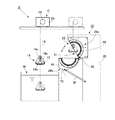
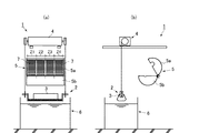
以下、本発明を図面に従って詳述する。図1は、本発明が適用された一実施例のシリコン破砕装置Aを示す構成図である。この図が示すように、本実施例のシリコン破砕装置Aは、大略、搬送装置C,シリコン加熱炉10及び冷却水槽Wで構成されている。   Hereinafter, the present invention will be described in detail with reference to the drawings. FIG. 1 is a configuration diagram showing a silicon crushing apparatus A according to an embodiment to which the present invention is applied. As shown in this figure, the silicon crushing apparatus A of this embodiment is generally composed of a transfer apparatus C, a silicon heating furnace 10 and a cooling water tank W.

搬送装置Cは、原料シリコン塊12が載置されるバスケット14と、バスケット14を吊下げるワイヤ16と、ワイヤ16の「巻取り」及び「繰出し」を行うウインチ18と、ウインチ18を水平方向へ走行させる走行装置20とで構成されており、原料シリコン塊12を破砕する際には、原料シリコン塊12が載置されたバスケット14が、まず、原料シリコン塊12と共にシリコン加熱炉10の内部へ搬入され、該加熱炉10でバスケット14と共に原料シリコン塊12を加熱した後、純水が満たされた冷却水槽Wの中に原料シリコン塊12と共にバスケット14が沈められる。   The transfer device C includes a basket 14 on which the raw material silicon lump 12 is placed, a wire 16 that suspends the basket 14, a winch 18 that “winds” and “feeds” the wire 16, and the winch 18 in the horizontal direction. When the raw silicon lump 12 is crushed, the basket 14 on which the raw silicon lump 12 is placed is first moved into the silicon heating furnace 10 together with the raw silicon lump 12. After carrying in and heating the raw material silicon lump 12 together with the basket 14 in the heating furnace 10, the basket 14 together with the raw material silicon lump 12 is submerged in the cooling water tank W filled with pure water.

搬送装置Cのバスケット14(図1)は、互いに対向して配設された2枚の側面プレート14aと、側面プレート14a間に架け渡され、且つ原料シリコン塊12が載置される複数のパイプ14bとを有しており、各側面プレート14aの上部にはワイヤ連結部14cが取り付けられており、このワイヤ連結部14cにワイヤ16が連結されている。したがって、後述するシリコン加熱炉10では、バスケット14及びワイヤ16との関係を考慮して、加熱室S1の大きさや、出入口22の開閉機構等が設計されている。   The basket 14 (FIG. 1) of the transfer device C includes two side plates 14a disposed opposite to each other, and a plurality of pipes that are spanned between the side plates 14a and on which the raw silicon block 12 is placed. 14b, and a wire connecting portion 14c is attached to the top of each side plate 14a, and a wire 16 is connected to the wire connecting portion 14c. Therefore, in the silicon heating furnace 10 to be described later, the size of the heating chamber S1, the opening / closing mechanism of the entrance / exit 22 and the like are designed in consideration of the relationship between the basket 14 and the wire 16.

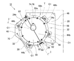
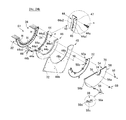
シリコン加熱炉10(図1〜5)は、バスケット14を収容する加熱室S1(図1)を有する円筒炉であり、2つの円筒炉半体24a,24b(具体的には、固定側の円筒炉半体24aと可動側の円筒炉半体24b)を、蝶番26(図3)を介して組み合わせることによって構成されている。そして、シリコン加熱炉10を使用する際には、図1及び図3に示すように、固定側の円筒炉半体24aが支持台28に取り付けられると共に、可動側の円筒炉半体24bに油圧シリンダ装置30が取り付けられ、油圧シリンダ装置30によって円筒炉半体24a,24bの開口部、すなわち出入口22が開閉される。   The silicon heating furnace 10 (FIGS. 1 to 5) is a cylindrical furnace having a heating chamber S1 (FIG. 1) in which a basket 14 is accommodated, and two cylindrical furnace halves 24a and 24b (specifically, fixed side cylinders). The furnace half 24a and the movable cylindrical furnace half 24b) are combined through a hinge 26 (FIG. 3). When the silicon heating furnace 10 is used, as shown in FIGS. 1 and 3, the fixed-side cylindrical furnace half 24a is attached to the support base 28, and the movable-side cylindrical furnace half 24b is hydraulically operated. The cylinder device 30 is attached, and the openings of the cylindrical furnace halves 24a and 24b, that is, the entrance / exit 22 are opened and closed by the hydraulic cylinder device 30.

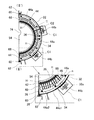
円筒炉半体24a,24bのそれぞれは、図2,図5及び図6に示すように、半円筒状のハウジング32を備えており、ハウジング32の内側には、図6に示すように、断熱材34、石英管64で被覆されたヒータH及び均熱材36がこの順に組み込まれており、ハウジング32の周方向両端部内面には、断熱材34の径方向への離脱を防止する断面略L字状の径方向離脱防止部材38が設けられている。そして、径方向離脱防止部材38には、断熱材34の周方向端面を覆う周方向端面被覆部材40が取り付けられており、断熱材34の周方向端面と周方向端面被覆部材40との間には、周方向端面冷却管42が配設されている。   Each of the cylindrical furnace halves 24a and 24b includes a semi-cylindrical housing 32 as shown in FIGS. 2, 5 and 6, and inside the housing 32, as shown in FIG. A material 34, a heater H covered with a quartz tube 64, and a heat equalizing material 36 are incorporated in this order, and the cross section of the inner surface of both ends in the circumferential direction of the housing 32 to prevent the heat insulating material 34 from coming off in the radial direction. An L-shaped radial direction separation preventing member 38 is provided. Further, a circumferential end face covering member 40 that covers the circumferential end face of the heat insulating material 34 is attached to the radial direction separation preventing member 38, and between the circumferential end face of the heat insulating material 34 and the circumferential end face covering member 40. Is provided with a circumferential end face cooling pipe 42.

一方、ハウジング32の軸方向両端部には、図7に示すように、複数のヒータHを並列に電気接続するブスバー44及び断熱材34の軸方向への離脱を防止する軸方向離脱防止部材46がこの順に取り付けられている。又、軸方向離脱防止部材46の表面には、取付板48ならびに2種類の支持部材50a及び50bが取り付けられており、支持部材50a及び50bのそれぞれには、側面冷却管52が接触して配置されている。更に、取付板48の表面には、加熱室S1の内側壁を構成する側壁構成部材54がカバー部材56と共に複数の取付具58によって取り付けられている。   On the other hand, as shown in FIG. 7, at both ends in the axial direction of the housing 32, the bus bar 44 for electrically connecting a plurality of heaters H in parallel and the axial detachment preventing member 46 for preventing the thermal insulation material 34 from detaching in the axial direction. Are installed in this order. A mounting plate 48 and two types of support members 50a and 50b are attached to the surface of the axial separation preventing member 46, and a side cooling pipe 52 is disposed in contact with each of the support members 50a and 50b. Has been. Further, a side wall constituting member 54 constituting an inner side wall of the heating chamber S <b> 1 is attached to the surface of the attachment plate 48 by a plurality of attachments 58 together with the cover member 56.

さらに、ハウジング32の周方向一方端部外面には、図5に示すように、断面略四角形のパイプ部材60がハウジング32の周方向端縁に沿って取り付けられており、固定側の円筒炉半体24aのパイプ部材60と可動側の円筒炉半体24bのパイプ部材60とが蝶番26を介して連結されている(図3参照)。又、各パイプ部材60には、ハウジング32の変形を防止する断面略L状或いは断面略コ字状の補強部材62が取り付けられている。   Further, as shown in FIG. 5, a pipe member 60 having a substantially square cross section is attached to the outer surface of one end portion in the circumferential direction of the housing 32 along the circumferential edge of the housing 32. The pipe member 60 of the body 24a and the pipe member 60 of the movable cylindrical furnace half 24b are connected via a hinge 26 (see FIG. 3). Further, a reinforcing member 62 having a substantially L-shaped cross section or a substantially U-shaped cross section for preventing deformation of the housing 32 is attached to each pipe member 60.

以下には、シリコン加熱炉10の各構成部材について、図面を参照しながらより詳細に説明する。   Below, each structural member of the silicon heating furnace 10 is demonstrated in detail, referring drawings.

ハウジング32は、円筒炉半体24a,24bの外周壁を構成するものであり、図6に示すように、ステンレス(SUS)等の金属からなる板材を半円筒状に曲げ加工することによって構成されている。このハウジング32の軸方向一方端部における周方向両端縁には、図7に示すように、周方向端面冷却管42の両端部42a,42bを外部へ導出するための切欠部63が形成されており、ハウジング34の周方向両端部内面における切欠部63を避けた位置には、図4及び図7に示すように、断面略L字状の径方向離脱防止部材38の一片が溶接またはネジ止め等によって取り付けられている。   The housing 32 constitutes the outer peripheral wall of the cylindrical furnace halves 24a and 24b, and is formed by bending a plate material made of metal such as stainless steel (SUS) into a semicylindrical shape as shown in FIG. ing. As shown in FIG. 7, notches 63 for leading both ends 42a and 42b of the circumferential end surface cooling pipe 42 to the outside are formed at both circumferential edges at one axial end of the housing 32. As shown in FIGS. 4 and 7, a piece of the radial separation preventing member 38 having a substantially L-shaped cross section is welded or screwed at a position avoiding the notch 63 on the inner surface of both ends in the circumferential direction of the housing 34. It is attached by etc.

また、図6に示すように、ハウジング32の軸方向両端部における所定位置には、後述するブスバー44の電極片44bを取り出すための電極取出孔32aが(本実施例の場合、周方向に各2カ所、ハウジング32全体として計4カ所)設けられており、ハウジング32の軸方向中央部における所定位置には、熱電対T(図5参照)を取り付けるための熱電対取付孔32bが設けられている。更に、ハウジング32の外表面には、図2に示すように、電極取出孔32aから取り出された電極片44b(後述)を保護する電極保護カバーC1が取り付けられると共に、熱電対取付孔32bに取り付けた熱電対Tを保護する熱電対保護カバーC2が取り付けられている。   Further, as shown in FIG. 6, at predetermined positions on both ends in the axial direction of the housing 32, there are electrode extraction holes 32a for extracting electrode pieces 44b of the bus bar 44 described later (in the case of the present embodiment, each in the circumferential direction). There are two locations, a total of four locations for the housing 32 as a whole), and a thermocouple mounting hole 32b for mounting a thermocouple T (see FIG. 5) is provided at a predetermined position in the central portion of the housing 32 in the axial direction. Yes. Further, as shown in FIG. 2, an electrode protective cover C1 for protecting an electrode piece 44b (described later) taken out from the electrode take-out hole 32a is attached to the outer surface of the housing 32, and attached to the thermocouple attachment hole 32b. A thermocouple protective cover C2 for protecting the thermocouple T is attached.

断熱材34は、ヒータHの熱がハウジング32に直接伝わるのを防止するものであり、図6に示すように、セラミック等のような断熱性及び耐熱性に優れた材料を半円筒状に加工することによって構成されている。そして、断熱材34の内周面には、胴長方向へ延びる複数の溝34aが周方向に所定の間隔を置いて形成されており、これらの溝34aにヒータHが収容される。   The heat insulating material 34 prevents the heat of the heater H from being directly transmitted to the housing 32. As shown in FIG. 6, a material having excellent heat insulating properties and heat resistance such as ceramic is processed into a semi-cylindrical shape. It is configured by A plurality of grooves 34a extending in the body length direction are formed at predetermined intervals in the circumferential direction on the inner peripheral surface of the heat insulating material 34, and the heater H is accommodated in these grooves 34a.

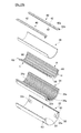
ヒータH(図4参照)は、棒状または線状(すなわち、直線状)の抵抗加熱ヒータであり、ハウジング32の胴長と略同等の長さに形成された石英管64と、カンタル線などからなり、この石英管64の内部に挿入された発熱体66とで構成されている。   The heater H (see FIG. 4) is a rod-shaped or linear (that is, linear) resistance heater, and is composed of a quartz tube 64 formed to a length substantially equal to the body length of the housing 32, and a Kanthal wire. The heating element 66 is inserted into the quartz tube 64.

ここで、ヒータH(より具体的には発熱体66)を被覆する石英管64は、透明な物及び不透明な物の何れも使用できるが、不透明な物を用いた場合、透明な物に比べてヒータHの熱容量をより一層増加させることができる。   Here, the quartz tube 64 covering the heater H (more specifically, the heating element 66) can use either a transparent material or an opaque material, but when an opaque material is used, it is compared with a transparent material. Thus, the heat capacity of the heater H can be further increased.

また、図4及び図5に示すように、ヒータHの長手方向両端部には、リード線68が接続されており、このリード線68の先端が後述するブスバー44のリード線接続部44aに電気的に接続されている。このため、独立した各ヒータHがブスバー44を介して電気的に並列接続されるようになっている。   As shown in FIGS. 4 and 5, lead wires 68 are connected to both ends in the longitudinal direction of the heater H, and the leading ends of the lead wires 68 are electrically connected to lead wire connecting portions 44a of the bus bar 44 described later. Connected. For this reason, the independent heaters H are electrically connected in parallel via the bus bar 44.

均熱材36は、ヒータHからの熱で均等に加熱されると共に、加熱室S1の内周壁を構成するものであり、石英ガラス等のような耐熱ガラスによって半円筒状に形成されている。この均熱材36を構成する耐熱ガラスは、金属不純物の放散がなく、且つ優れた耐熱性を有するものである。従って、断熱材34及びヒータHの内側にこのような耐熱ガラスからなる均熱材36を配設してシリコン加熱炉10を構成することによって、断熱材34から放散された金属不純物が加熱室S1内へと拡散するのを防止できると共に、炉内の大熱容量化を図ることができ、ヒータHからの熱を均熱材36を介して加熱室S1内へ均等に放射することができる。   The soaking material 36 is uniformly heated by the heat from the heater H and constitutes the inner peripheral wall of the heating chamber S1, and is formed in a semi-cylindrical shape by heat-resistant glass such as quartz glass. The heat-resistant glass constituting the soaking material 36 does not diffuse metal impurities and has excellent heat resistance. Therefore, by arranging the heat equalizing material 36 made of such heat-resistant glass inside the heat insulating material 34 and the heater H to constitute the silicon heating furnace 10, metal impurities diffused from the heat insulating material 34 are heated in the heating chamber S1. While being able to prevent diffusion into the inside, it is possible to increase the heat capacity in the furnace, and heat from the heater H can be evenly radiated into the heating chamber S1 through the soaking material 36.

なお、均熱材36を構成する耐熱ガラスは、上述した石英管64と同様、透明な物及び不透明な物の何れも使用することができる。   In addition, the heat resistant glass which comprises the soaking | uniform-heating material 36 can use both a transparent thing and an opaque thing like the quartz tube 64 mentioned above.

周方向端面被覆部材40は、断熱材34の周方向端面を覆うことによって断熱材34から放散された金属不純物が加熱室S1内に拡散するのを防止するものであり、図4及び図6に示すように、チタン等のような耐熱性に優れ、且つ熱拡散の生じ難い材料によって帯板状に形成されている。なお、この周方向端面被覆部材40は、径方向離脱防止部材38に螺子止めされる。   The circumferential end surface covering member 40 prevents the metal impurities diffused from the heat insulating material 34 from diffusing into the heating chamber S1 by covering the circumferential end surface of the heat insulating material 34. FIG. 4 and FIG. As shown, it is formed in a strip shape from a material having excellent heat resistance, such as titanium, which hardly causes thermal diffusion. The circumferential end face covering member 40 is screwed to the radial direction separation preventing member 38.

周方向端面冷却管42は、チタン等のような耐熱性に優れ、且つ熱拡散の生じ難い材料からなる管材を略U字状に曲げることによって構成された「通水管」であり、図4及び図6に示すように、断熱材34の周方向端面と周方向端面被覆部材40との間において、周方向端面の全長に亘って配設されている。また、この周方向端面冷却管42における冷媒の流入口及び流出口となる両端部42a,42bは、ハウジング32の切欠部63からシリコン加熱炉10の外部へと導出されている。   The circumferential end surface cooling pipe 42 is a “water pipe” formed by bending a pipe material made of a material having excellent heat resistance such as titanium or the like and hardly causing thermal diffusion into a substantially U shape. As shown in FIG. 6, between the circumferential end face of the heat insulating material 34 and the circumferential end face covering member 40, it is disposed over the entire length of the circumferential end face. Further, both end portions 42 a and 42 b serving as the refrigerant inlet and outlet in the circumferential end surface cooling pipe 42 are led out from the notch 63 of the housing 32 to the outside of the silicon heating furnace 10.

ここで、周方向端面被覆部材40と周方向端面冷却管42とは、互いに独立して配設されてもよいが、本実施例では、周方向端面被覆部材40の裏面に周方向端面冷却管42が溶接されている。したがって、本実施例では、周方向端面被覆部材40を径方向離脱防止部材38に取り付けると同時に周方向端面冷却管42を位置決めでき、周方向端面冷却管42の位置決めの手間を軽減できる。また、周方向端面被覆部材40を周方向端面冷却管42によって効率よく冷却できる。   Here, the circumferential end face covering member 40 and the circumferential end face cooling pipe 42 may be disposed independently of each other, but in this embodiment, the circumferential end face cooling pipe is provided on the back surface of the circumferential end face covering member 40. 42 is welded. Therefore, in the present embodiment, the circumferential end surface cooling pipe 42 can be positioned at the same time as the circumferential end surface covering member 40 is attached to the radial direction separation preventing member 38, and the positioning effort of the circumferential end surface cooling pipe 42 can be reduced. Further, the circumferential end face covering member 40 can be efficiently cooled by the circumferential end face cooling pipe 42.

ブスバー44は、耐熱性と導電性とに優れた金属材料からなる電極部材であり、図4、図5及び図7に示すように、断熱材34の軸方向端面外縁部に配置され、ヒータHのリード線68が接続される円弧板状のリード線接続片44a1と、該リード線接続片44a1の外周縁から略垂直に曲折して断熱材34の外周面に当接する外周当接片44a2とで構成された円弧状のリード線接続部44a、及び外周当接片44a2の先端から突出した電極片44bを有する。   The bus bar 44 is an electrode member made of a metal material excellent in heat resistance and conductivity, and is disposed on the outer edge portion of the end surface in the axial direction of the heat insulating material 34 as shown in FIGS. 4, 5, and 7. An arc-shaped plate-like lead wire connecting piece 44a1 to which the lead wire 68 is connected, and an outer peripheral abutting piece 44a2 which is bent substantially perpendicularly from the outer peripheral edge of the lead wire connecting piece 44a1 and comes into contact with the outer peripheral surface of the heat insulating material And an electrode piece 44b protruding from the tip of the outer peripheral contact piece 44a2.

このうちリード線接続部44aを構成するリード線接続片44a1の内周縁側には、同一円弧上に複数のリード線取付孔45が穿設されており、このリード線取付孔45のそれぞれに、各ヒータHのリード線68の先端が係脱自在に取り付けられる。   Among them, a plurality of lead wire mounting holes 45 are formed on the same arc on the inner peripheral edge side of the lead wire connecting piece 44a1 constituting the lead wire connecting portion 44a. The tip of the lead wire 68 of each heater H is removably attached.

また、リード線接続片44a1の外周縁側には、ブスバー44を断熱材34の軸方向端面に螺子止めする際に固定ネジnが挿通される複数のネジ孔47が穿設されている。   In addition, a plurality of screw holes 47 through which the fixing screw n is inserted when the bus bar 44 is screwed to the end surface in the axial direction of the heat insulating material 34 are formed on the outer peripheral edge side of the lead wire connecting piece 44a1.

ここで、本実施例のシリコン加熱炉10では、円筒炉半体24a,24bのそれぞれの胴長方向両端部に2つのブスバー44が取り付けられている。このため、円筒炉半体24a,24bが周方向にて2つのゾーンに分割されると共に、各ゾーン別個にヒータHの温度制御ができるようになっている。   Here, in the silicon heating furnace 10 of the present embodiment, two bus bars 44 are attached to both ends of the cylindrical furnace halves 24a and 24b in the body length direction. For this reason, the cylindrical furnace halves 24a and 24b are divided into two zones in the circumferential direction, and the temperature of the heater H can be controlled separately for each zone.

軸方向離脱防止部材46は、断熱材34の軸方向端面側に配設され断熱材34の軸方向への離脱を防止するものであり、図4及び図7に示すように、断熱材34の軸方向端面と均熱材36とハウジング32とで囲まれたハウジング32の軸方向両端部の空間に嵌め込まれる略半円弧状の部材である。   The axial detachment preventing member 46 is disposed on the axial end face side of the heat insulating material 34 to prevent the heat insulating material 34 from detaching in the axial direction. As shown in FIGS. It is a substantially semicircular arc-shaped member that is fitted into the space at both ends in the axial direction of the housing 32 surrounded by the end surface in the axial direction, the soaking material 36 and the housing 32.

取付板48は、図7に示すように、板材の一部に半円状の切欠部48aを設けることによって形成された部材で、この取付板48表面の所定位置には複数のネジ孔48bが設けられており、取付ネジ70を介して軸方向離脱防止部材46の表面に固定されている。   As shown in FIG. 7, the mounting plate 48 is a member formed by providing a semicircular cutout portion 48 a in a part of a plate material, and a plurality of screw holes 48 b are formed at predetermined positions on the surface of the mounting plate 48. It is provided and fixed to the surface of the axial detachment preventing member 46 via a mounting screw 70.

なお、取付板48の形状は、図2及び図3に示すように、円筒炉半体24a及び24bのそれぞれで相違しており、固定側の円筒炉半体24aにおける取付板48の形状は、取付対象となる支持台28の形状に応じて設定されており、可動側の円筒炉半体24bにおける取付板48の形状は、油圧シリンダ装置30を取り付ける取付部72を確保できるように設定されている。   2 and 3, the shape of the mounting plate 48 is different in each of the cylindrical furnace halves 24a and 24b, and the shape of the mounting plate 48 in the fixed-side cylindrical furnace half 24a is It is set according to the shape of the support base 28 to be attached, and the shape of the attachment plate 48 in the movable cylindrical furnace half 24b is set so as to secure the attachment portion 72 for attaching the hydraulic cylinder device 30. Yes.

支持部材50a及び50bは、均熱材36と軸方向離脱防止部材46とに螺子止めされることにより、均熱材36の軸方向端部を支持するものであり、均熱材36の支持対象部分に応じて使い分けられる。具体的には、支持部材50aは、均熱材36の軸方向端部をその周方向端部において支持するものであり、支持部材50bは、均熱材36の軸方向端部をその周方向端部以外の部分で支持するものである。   The support members 50 a and 50 b are screwed to the soaking material 36 and the axial detachment preventing member 46, thereby supporting the axial end of the soaking material 36. It is used properly according to the part. Specifically, the support member 50a supports the axial end portion of the heat equalizing material 36 at its circumferential end portion, and the support member 50b supports the axial end portion of the heat equalizing material 36 in its circumferential direction. It is supported by a part other than the end part.

この支持部材50a及び50bの材質は、特に限定されるものではないが、原料シリコン塊12の金属汚染を防止するためには、チタン等のような耐熱性に優れ、且つ熱拡散の生じ難い材料を用いることが望ましい。   The material of the support members 50a and 50b is not particularly limited. However, in order to prevent metal contamination of the raw material silicon lump 12, a material that has excellent heat resistance such as titanium or the like and hardly causes thermal diffusion. It is desirable to use

側面冷却管52は、チタン等のような耐熱性に優れ、且つ熱拡散の生じ難い材料からなる「通水管」であり、図7に示すように、全ての支持部材50a及び50bに接触するようにして配設されている。つまり、側面冷却管52は、断熱材34の外周縁及び周方向端縁ならびに均熱材36の内周縁に沿って配設されており、側面冷却管52の両端部は、ハウジング32の略中央部においてハウジング32の外側へと導出するように配設されている。   The side cooling pipe 52 is a “water pipe” made of a material having excellent heat resistance such as titanium and hardly causing thermal diffusion, and as shown in FIG. 7, it is in contact with all the supporting members 50a and 50b. Arranged. That is, the side surface cooling pipe 52 is disposed along the outer peripheral edge and the circumferential edge of the heat insulating material 34 and the inner peripheral edge of the heat equalizing material 36, and both end portions of the side surface cooling pipe 52 are substantially at the center of the housing 32. It arrange | positions so that it may guide | emit to the outer side of the housing 32 in a part.

支持部材50a及び50bと側面冷却管52とは、互いに独立して配設されてもよいが、本実施例では、各支持部材50a及び50bに側面冷却管52が溶接されている。したがって、本実施例では、支持部材50a及び50bを軸方向離脱防止部材46に取り付けると同時に側面冷却管52を位置決めでき、側面冷却管52の位置決めの手間を軽減できる。また、各支持部材50a及び50bを側面冷却管52によって効率よく冷却できる。   The support members 50a and 50b and the side surface cooling pipe 52 may be disposed independently of each other, but in this embodiment, the side surface cooling pipe 52 is welded to each of the support members 50a and 50b. Therefore, in the present embodiment, the side cooling pipe 52 can be positioned at the same time that the support members 50a and 50b are attached to the axial direction separation preventing member 46, and the labor for positioning the side cooling pipe 52 can be reduced. In addition, the support members 50 a and 50 b can be efficiently cooled by the side cooling pipe 52.

側壁構成部材54は、図4及び図7に示すように、断熱材34の軸方向端面を軸方向離脱防止部材46及び取付板48の表面側から覆うとともに加熱室S1の内側壁を構成するものであり、石英ガラス等のような耐熱ガラスによって半円盤状に形成されている。この側壁構成部材54には、加熱室S1に収容されたバスケット14のワイヤ連結部14cを外部へ導出させるための略円形の窓74が形成されている。   As shown in FIGS. 4 and 7, the side wall constituting member 54 covers the axial end surface of the heat insulating material 34 from the surface side of the axial detachment preventing member 46 and the mounting plate 48 and constitutes the inner side wall of the heating chamber S <b> 1. It is formed in a semi-disc shape from heat-resistant glass such as quartz glass. The side wall constituting member 54 is formed with a substantially circular window 74 through which the wire connecting portion 14c of the basket 14 accommodated in the heating chamber S1 is led out.

カバー部材56は、図4及び図7に示すように、側壁構成部材54を覆い隠すものであり、側壁構成部材54と対向して配設される半円盤状のカバー板部56aと、カバー板部56aの外周縁から垂直に立ち上がって形成され、側壁構成部材54を収容する空間を構成する周壁部56bとを有しており、カバー板部56aには、側壁構成部材54の窓74に対応する略円形の窓76が形成されている。   As shown in FIGS. 4 and 7, the cover member 56 covers the side wall constituting member 54, and includes a semi-disc-shaped cover plate portion 56 a disposed to face the side wall constituting member 54, and a cover plate. And a peripheral wall portion 56b that forms a space for accommodating the side wall constituting member 54. The cover plate portion 56a corresponds to the window 74 of the side wall constituting member 54. A substantially circular window 76 is formed.

なお、カバー板部56aと側壁構成部材54との間には、セラミックシートなどからなる断熱材78が配設されている。又、図2及び図3に示すように、カバー部材56の窓76には、これを開閉自在に封鎖する蓋体80が設けられている。   A heat insulating material 78 made of a ceramic sheet or the like is disposed between the cover plate portion 56a and the side wall constituting member 54. As shown in FIGS. 2 and 3, the window 76 of the cover member 56 is provided with a lid body 80 that can be opened and closed.

取付具58は、図3及び図7に示すように、側壁構成部材54が取り付けられたカバー部材56を取付板48に取り付けるためのものであり、互いに平行な一対の取付板部58a及び58bと、これらを連結する連結板部58cとで構成された略「Z」字状の部材である。この取付具58は、取付板部58aをカバー板材56の外縁に螺子止めすると共に、取付板部58bを取付板48に螺子止めすることにより、カバー部材56を取付板48に着脱可能に固定する。   As shown in FIGS. 3 and 7, the attachment 58 is for attaching the cover member 56 to which the side wall constituting member 54 is attached to the attachment plate 48, and a pair of attachment plate portions 58a and 58b parallel to each other. , A substantially “Z” -shaped member composed of a connecting plate portion 58c for connecting them. The attachment 58 is configured such that the attachment plate portion 58 a is screwed to the outer edge of the cover plate material 56 and the attachment plate portion 58 b is screwed to the attachment plate 48, so that the cover member 56 is detachably fixed to the attachment plate 48. .

本実施例によれば、円筒炉半体24a,24bに内蔵される複数のヒータHが、円筒炉半体24a,24bの胴長と略同等の長さに形成されると共に、円筒炉半体24a,24bの内周方向にて互いに離間し且つ円筒炉半体24a,24bの胴長方向に沿って配置されているので、図5に示すように、円筒炉半体24a,24b内に多数本の独立したヒータHを配設することができる。その結果、或るヒータHが断線したとしても、断線したヒータHに隣接して並行する一対のヒータHで断線したヒータHの発熱量を補うことができ、炉内の加熱バランスが大きく崩れるのを防止することができる。   According to the present embodiment, the plurality of heaters H built in the cylindrical furnace halves 24a and 24b are formed to have a length substantially equal to the barrel length of the cylindrical furnace halves 24a and 24b, and the cylindrical furnace halves. Since they are spaced apart from each other in the inner circumferential direction of 24a and 24b and along the trunk length direction of the cylindrical furnace halves 24a and 24b, as shown in FIG. A book independent heater H can be provided. As a result, even if a certain heater H is disconnected, the amount of heat generated by the disconnected heater H can be compensated by a pair of heaters H adjacent to the disconnected heater H, and the heating balance in the furnace is greatly disrupted. Can be prevented.

また、円筒炉半体24a,24bの内部にて、上述のように配置されたヒータHの長手方向両端部は、図4に示すように、円筒炉半体24a,24bの側面側に配置されるようになる。このため、螺子止めされた取付具58を取り外し、取付板48からカバー部材56と側壁構成部材54とを取り外すだけで、ヒータHの端部が外部に露出するようになる。つまり、ヒータHの交換に際して円筒炉半体24a,24bを全て分解する必要がなく、断線したヒータHを円筒炉半体24a,24bの側面から交換することができ、ヒータ交換に掛かる時間やコストを大幅に低減することができる。   Also, the longitudinal ends of the heater H arranged as described above inside the cylindrical furnace halves 24a and 24b are arranged on the side surfaces of the cylindrical furnace halves 24a and 24b as shown in FIG. Become so. For this reason, the end portion of the heater H is exposed to the outside only by removing the screw-fastened attachment 58 and removing the cover member 56 and the side wall constituting member 54 from the attachment plate 48. That is, it is not necessary to disassemble all the cylindrical furnace halves 24a and 24b when replacing the heater H, the disconnected heater H can be replaced from the side of the cylindrical furnace halves 24a and 24b, and the time and cost required for heater replacement Can be greatly reduced.

本発明の一実施例のシリコン破砕装置を示す構成図である。It is a block diagram which shows the silicon | silicone crushing apparatus of one Example of this invention. 本発明の一実施例のシリコン加熱炉を示す斜視図である。It is a perspective view which shows the silicon heating furnace of one Example of this invention. 図2におけるX矢視図である。FIG. 3 is an X arrow view in FIG. 2. 図3におけるI−I’線断面図である。FIG. 4 is a sectional view taken along line I-I ′ in FIG. 3. 図4におけるII−II’線断面図である。It is the II-II 'sectional view taken on the line in FIG. 円筒炉半体を示す径方向の分解斜視図である。It is a disassembled perspective view of the radial direction which shows a cylindrical furnace half body. 円筒炉半体を示す軸方向の分解斜視図である。It is a disassembled perspective view of the axial direction which shows a cylindrical furnace half body. 従来のシリコン破砕装置の概略を示す(a)正面図および(b)右側面図である。It is (a) front view and (b) right view which show the outline of the conventional silicon crushing apparatus.

符号の説明Explanation of symbols

10…シリコン加熱炉
12…原料シリコン
24a,24b…円筒炉半体
26…蝶番
28…支持台
30…油圧シリンダ装置
32…ハウジング
34…断熱材
36…均熱材
38…径方向離脱防止部材
40…周方向端面被覆部材
42…周方向端面冷却管
44…ブスバー
46…軸方向離脱防止部材
48…取付板
50a,50b…支持部材
52…側面冷却管
54…側壁構成部材
56…カバー部材
58…取付具
64…石英管
66…発熱体
68…リード線
A…シリコン破砕装置
H…ヒータ
C…搬送装置
W…冷却水槽
T…熱電対
DESCRIPTION OF SYMBOLS 10 ... Silicon heating furnace 12 ... Raw material silicon | silicone 24a, 24b ... Cylindrical furnace half body 26 ... Hinge 28 ... Support stand 30 ... Hydraulic cylinder apparatus 32 ... Housing 34 ... Heat insulating material 36 ... Heat equalizing material 38 ... Radial direction separation prevention member 40 ... Circumferential end face covering member 42 ... circumferential end face cooling pipe 44 ... bus bar 46 ... axial detachment preventing member 48 ... mounting plate 50a, 50b ... support member 52 ... side cooling pipe 54 ... side wall constituent member 56 ... cover member 58 ... fixture 64 ... quartz tube 66 ... heating element 68 ... lead wire A ... silicon crushing device H ... heater C ... transport device W ... cooling water tank T ... thermocouple

Claims (4)

2つの円筒炉半体を円筒状に組み合わせることによって構成され、その内部にて加熱対象となる原料シリコン塊を加熱するシリコン加熱炉であって、
前記円筒炉半体の胴長と略同等の長さに形成され、且つ石英管で被覆された複数の直線状のヒータと、
前記円筒炉半体の胴長方向両端側に配置され、前記各ヒータの長手方向両端部に接続されたリード線が係脱自在に接続されるブスバーとを具備し、
前記2つの円筒炉半体の内側に、前記複数の直線状のヒータが、前記円筒炉半体の内周方向にて互いに離間し且つ前記円筒炉半体の胴長方向に沿って配列されると共に、前記ヒータのそれぞれが、その長手方向両端部において前記ブスバーを介して電気的に並列接続されていることを特徴とするシリコン加熱炉。
A silicon heating furnace that is configured by combining two cylindrical furnace halves in a cylindrical shape and heats a raw material silicon lump to be heated inside,
A plurality of linear heaters formed in a length substantially equal to the length of the cylindrical furnace half and covered with a quartz tube;
A bus bar which is disposed on both ends of the cylindrical furnace half in the body length direction, and which is connected to the both ends in the longitudinal direction of the heaters so as to be detachable;
Inside the two cylindrical furnace halves, the plurality of linear heaters are spaced apart from each other in the inner circumferential direction of the cylindrical furnace halves and arranged along the trunk length direction of the cylindrical furnace halves. In addition, each of the heaters is electrically connected in parallel via the bus bars at both ends in the longitudinal direction.
前記円筒炉半体の内側に取り付けられた半円筒状の断熱材の内周面に、前記断熱材の胴長方向に延びて前記ヒータをスライド自在に収容する収容溝が、周方向に所定の間隔を置いて堀設されていることを特徴とする請求項1に記載のシリコン加熱炉。   On the inner peripheral surface of the semi-cylindrical heat insulating material attached to the inside of the cylindrical furnace half, an accommodation groove that extends in the body length direction of the heat insulating material and slidably accommodates the heater is predetermined in the circumferential direction. The silicon heating furnace according to claim 1, wherein the silicon heating furnace is dug at intervals. 前記円筒炉半体を周方向にて複数のゾーンに分割し、前記ヒータを分割した各ゾーン毎に制御することを特徴とする請求項1又は2に記載のシリコン加熱炉。   3. The silicon heating furnace according to claim 1, wherein the cylindrical furnace half is divided into a plurality of zones in the circumferential direction, and the heater is controlled for each divided zone. 原料シリコンを搬送する搬送装置と、
前記原料シリコンを加熱する請求項1乃至3の何れかに記載のシリコン加熱炉と、
前記シリコン加熱炉で加熱した原料シリコンを水没させて急冷する冷却水槽とで構成されていることを特徴とするシリコン破砕装置。


A transfer device for transferring raw material silicon;
The silicon heating furnace according to any one of claims 1 to 3, wherein the raw silicon is heated;
A silicon crushing apparatus comprising: a cooling water tank that submerged and rapidly cools raw silicon heated in the silicon heating furnace.


JP2008179488A 2008-07-09 2008-07-09 Silicon heating furnace and silicon crusher using the same Expired - Fee Related JP5198169B2 (en)

Priority Applications (1)

Application Number Priority Date Filing Date Title
JP2008179488A JP5198169B2 (en) 2008-07-09 2008-07-09 Silicon heating furnace and silicon crusher using the same

Applications Claiming Priority (1)

Application Number Priority Date Filing Date Title
JP2008179488A JP5198169B2 (en) 2008-07-09 2008-07-09 Silicon heating furnace and silicon crusher using the same

Publications (2)

Publication Number Publication Date
JP2010017635A true JP2010017635A (en) 2010-01-28
JP5198169B2 JP5198169B2 (en) 2013-05-15

Family

ID=41703040

Family Applications (1)

Application Number Title Priority Date Filing Date
JP2008179488A Expired - Fee Related JP5198169B2 (en) 2008-07-09 2008-07-09 Silicon heating furnace and silicon crusher using the same

Country Status (1)

Country Link
JP (1) JP5198169B2 (en)

Cited By (2)

* Cited by examiner, † Cited by third party
Publication number Priority date Publication date Assignee Title
CN113774493A (en) * 2021-09-30 2021-12-10 吴利德 Continuous efficient crystalline silicon stress release equipment
JP2022176040A (en) * 2021-05-12 2022-11-25 コヨ サーモ システム コリア カンパニー リミテッド Heater power source connection device for heat treatment oven

Families Citing this family (1)

* Cited by examiner, † Cited by third party
Publication number Priority date Publication date Assignee Title
CN103599835B (en) * 2013-11-20 2016-06-15 宁夏宁电光伏材料有限公司 A kind of silico briquette breaking method

Citations (6)

* Cited by examiner, † Cited by third party
Publication number Priority date Publication date Assignee Title
JPH0261979A (en) * 1988-08-26 1990-03-01 Matsushita Electric Ind Co Ltd Heater and cooking utensil
JPH07253276A (en) * 1994-03-16 1995-10-03 Tokyo Electron Ltd Heat treating furnace, and manufacture thereof
JP2000208236A (en) * 1999-01-08 2000-07-28 Daido Steel Co Ltd Seramic heater installing structure on furnace wall
JP2005288332A (en) * 2004-03-31 2005-10-20 Mitsubishi Materials Polycrystalline Silicon Corp Crushing method of polycrystalline silicon rod
WO2009019749A1 (en) * 2007-08-03 2009-02-12 Teoss Co., Ltd. Silicon supporting device and silicon heating rapidly cooling apparatus utilizing the same
WO2009019756A1 (en) * 2007-08-06 2009-02-12 Teoss Co., Ltd. Silicon heating furnace

Patent Citations (6)

* Cited by examiner, † Cited by third party
Publication number Priority date Publication date Assignee Title
JPH0261979A (en) * 1988-08-26 1990-03-01 Matsushita Electric Ind Co Ltd Heater and cooking utensil
JPH07253276A (en) * 1994-03-16 1995-10-03 Tokyo Electron Ltd Heat treating furnace, and manufacture thereof
JP2000208236A (en) * 1999-01-08 2000-07-28 Daido Steel Co Ltd Seramic heater installing structure on furnace wall
JP2005288332A (en) * 2004-03-31 2005-10-20 Mitsubishi Materials Polycrystalline Silicon Corp Crushing method of polycrystalline silicon rod
WO2009019749A1 (en) * 2007-08-03 2009-02-12 Teoss Co., Ltd. Silicon supporting device and silicon heating rapidly cooling apparatus utilizing the same
WO2009019756A1 (en) * 2007-08-06 2009-02-12 Teoss Co., Ltd. Silicon heating furnace

Cited By (3)

* Cited by examiner, † Cited by third party
Publication number Priority date Publication date Assignee Title
JP2022176040A (en) * 2021-05-12 2022-11-25 コヨ サーモ システム コリア カンパニー リミテッド Heater power source connection device for heat treatment oven
JP7387692B2 (en) 2021-05-12 2023-11-28 株式会社韓国ジェイテクトサーモシステム Heat treatment oven heater power connection device
CN113774493A (en) * 2021-09-30 2021-12-10 吴利德 Continuous efficient crystalline silicon stress release equipment

Also Published As

Publication number Publication date
JP5198169B2 (en) 2013-05-15

Similar Documents

Publication Publication Date Title
JP5198169B2 (en) Silicon heating furnace and silicon crusher using the same
JP5564150B2 (en) Cold crucible induction melting furnace integrated with induction coil and melting furnace
JP4950360B2 (en) Method and apparatus for semi-continuous casting of hollow ingot
TWI727124B (en) Glass manufacturing method and preheating method of glass supply pipe
JP5953368B2 (en) Apparatus and method for producing polycrystalline material having large particle size
SU629902A3 (en) Melting furnace
EP1774069B1 (en) Apparatus for growing single crystals from melt
JP4399026B2 (en) Silicon heating furnace
Bellmann et al. Silica versus silicon nitride crucible: Influence of thermophysical properties on the solidification of multi-crystalline silicon by Bridgman technique
EP2138468B1 (en) Water-cooled mold
JP7085546B2 (en) Methods and equipment for compensating for dimensional fluctuations in the molding body
KR20110056635A (en) Multi-crystal silicon ingot manufacture apparatus for production of solar cell
KR101573035B1 (en) Apparatus for processing substrate
KR101907708B1 (en) Single crystal pulling device and low heat conductive member to be used in single crystal pulling device
JP2009190001A (en) Crushing apparatus and crushing method of polycrystalline silicon rod
US20110100978A1 (en) Apparatus for shaping melts comprising inorganic oxides or minerals with an improved heating device
JP5449645B2 (en) A method of manufacturing a silicon plate for heat treatment.
KR101774040B1 (en) Cooling structure for ingot growing apparatus
KR101288441B1 (en) Heater for sublimation refinement and method for forming the same
JP6772753B2 (en) Polycrystalline silicon reactor
NO813605L (en) ELECTRO STOVES FOR ELECTRIC Ovens.
WO2012027522A2 (en) System and method for heating material samples
JP5894486B2 (en) Forging die apparatus and die attaching / detaching method
JP2002211942A (en) Drawing machine for glass perform
Kund Use of Rheocasting Mould in SSM Processing

Legal Events

Date Code Title Description
A621 Written request for application examination

Free format text: JAPANESE INTERMEDIATE CODE: A621

Effective date: 20100219

TRDD Decision of grant or rejection written
A01 Written decision to grant a patent or to grant a registration (utility model)

Free format text: JAPANESE INTERMEDIATE CODE: A01

Effective date: 20130108

A61 First payment of annual fees (during grant procedure)

Free format text: JAPANESE INTERMEDIATE CODE: A61

Effective date: 20130206

FPAY Renewal fee payment (event date is renewal date of database)

Free format text: PAYMENT UNTIL: 20160215

Year of fee payment: 3

R150 Certificate of patent or registration of utility model

Ref document number: 5198169

Country of ref document: JP

Free format text: JAPANESE INTERMEDIATE CODE: R150

Free format text: JAPANESE INTERMEDIATE CODE: R150

S111 Request for change of ownership or part of ownership

Free format text: JAPANESE INTERMEDIATE CODE: R313113

R350 Written notification of registration of transfer

Free format text: JAPANESE INTERMEDIATE CODE: R350

FPAY Renewal fee payment (event date is renewal date of database)

Free format text: PAYMENT UNTIL: 20160215

Year of fee payment: 3

R250 Receipt of annual fees

Free format text: JAPANESE INTERMEDIATE CODE: R250

R250 Receipt of annual fees

Free format text: JAPANESE INTERMEDIATE CODE: R250

R250 Receipt of annual fees

Free format text: JAPANESE INTERMEDIATE CODE: R250

R250 Receipt of annual fees

Free format text: JAPANESE INTERMEDIATE CODE: R250

R250 Receipt of annual fees

Free format text: JAPANESE INTERMEDIATE CODE: R250

LAPS Cancellation because of no payment of annual fees