JP5953368B2 - Apparatus and method for producing polycrystalline material having large particle size - Google Patents
Apparatus and method for producing polycrystalline material having large particle size Download PDFInfo
- Publication number
- JP5953368B2 JP5953368B2 JP2014509339A JP2014509339A JP5953368B2 JP 5953368 B2 JP5953368 B2 JP 5953368B2 JP 2014509339 A JP2014509339 A JP 2014509339A JP 2014509339 A JP2014509339 A JP 2014509339A JP 5953368 B2 JP5953368 B2 JP 5953368B2
- Authority
- JP
- Japan
- Prior art keywords
- crucible
- frame
- support block
- bottom plate
- void
- Prior art date
- Legal status (The legal status is an assumption and is not a legal conclusion. Google has not performed a legal analysis and makes no representation as to the accuracy of the status listed.)
- Expired - Fee Related
Links
Images


Classifications
-
- C—CHEMISTRY; METALLURGY
- C30—CRYSTAL GROWTH
- C30B—SINGLE-CRYSTAL GROWTH; UNIDIRECTIONAL SOLIDIFICATION OF EUTECTIC MATERIAL OR UNIDIRECTIONAL DEMIXING OF EUTECTOID MATERIAL; REFINING BY ZONE-MELTING OF MATERIAL; PRODUCTION OF A HOMOGENEOUS POLYCRYSTALLINE MATERIAL WITH DEFINED STRUCTURE; SINGLE CRYSTALS OR HOMOGENEOUS POLYCRYSTALLINE MATERIAL WITH DEFINED STRUCTURE; AFTER-TREATMENT OF SINGLE CRYSTALS OR A HOMOGENEOUS POLYCRYSTALLINE MATERIAL WITH DEFINED STRUCTURE; APPARATUS THEREFOR
- C30B11/00—Single-crystal growth by normal freezing or freezing under temperature gradient, e.g. Bridgman-Stockbarger method
- C30B11/002—Crucibles or containers for supporting the melt
-
- C—CHEMISTRY; METALLURGY
- C30—CRYSTAL GROWTH
- C30B—SINGLE-CRYSTAL GROWTH; UNIDIRECTIONAL SOLIDIFICATION OF EUTECTIC MATERIAL OR UNIDIRECTIONAL DEMIXING OF EUTECTOID MATERIAL; REFINING BY ZONE-MELTING OF MATERIAL; PRODUCTION OF A HOMOGENEOUS POLYCRYSTALLINE MATERIAL WITH DEFINED STRUCTURE; SINGLE CRYSTALS OR HOMOGENEOUS POLYCRYSTALLINE MATERIAL WITH DEFINED STRUCTURE; AFTER-TREATMENT OF SINGLE CRYSTALS OR A HOMOGENEOUS POLYCRYSTALLINE MATERIAL WITH DEFINED STRUCTURE; APPARATUS THEREFOR
- C30B11/00—Single-crystal growth by normal freezing or freezing under temperature gradient, e.g. Bridgman-Stockbarger method
- C30B11/003—Heating or cooling of the melt or the crystallised material
-
- C—CHEMISTRY; METALLURGY
- C30—CRYSTAL GROWTH
- C30B—SINGLE-CRYSTAL GROWTH; UNIDIRECTIONAL SOLIDIFICATION OF EUTECTIC MATERIAL OR UNIDIRECTIONAL DEMIXING OF EUTECTOID MATERIAL; REFINING BY ZONE-MELTING OF MATERIAL; PRODUCTION OF A HOMOGENEOUS POLYCRYSTALLINE MATERIAL WITH DEFINED STRUCTURE; SINGLE CRYSTALS OR HOMOGENEOUS POLYCRYSTALLINE MATERIAL WITH DEFINED STRUCTURE; AFTER-TREATMENT OF SINGLE CRYSTALS OR A HOMOGENEOUS POLYCRYSTALLINE MATERIAL WITH DEFINED STRUCTURE; APPARATUS THEREFOR
- C30B29/00—Single crystals or homogeneous polycrystalline material with defined structure characterised by the material or by their shape
- C30B29/02—Elements
- C30B29/06—Silicon
-
- C—CHEMISTRY; METALLURGY
- C30—CRYSTAL GROWTH
- C30B—SINGLE-CRYSTAL GROWTH; UNIDIRECTIONAL SOLIDIFICATION OF EUTECTIC MATERIAL OR UNIDIRECTIONAL DEMIXING OF EUTECTOID MATERIAL; REFINING BY ZONE-MELTING OF MATERIAL; PRODUCTION OF A HOMOGENEOUS POLYCRYSTALLINE MATERIAL WITH DEFINED STRUCTURE; SINGLE CRYSTALS OR HOMOGENEOUS POLYCRYSTALLINE MATERIAL WITH DEFINED STRUCTURE; AFTER-TREATMENT OF SINGLE CRYSTALS OR A HOMOGENEOUS POLYCRYSTALLINE MATERIAL WITH DEFINED STRUCTURE; APPARATUS THEREFOR
- C30B35/00—Apparatus not otherwise provided for, specially adapted for the growth, production or after-treatment of single crystals or of a homogeneous polycrystalline material with defined structure
Landscapes
- Chemical & Material Sciences (AREA)
- Engineering & Computer Science (AREA)
- Crystallography & Structural Chemistry (AREA)
- Materials Engineering (AREA)
- Metallurgy (AREA)
- Organic Chemistry (AREA)
- Crystals, And After-Treatments Of Crystals (AREA)
- Silicon Compounds (AREA)
Description
関連出願
本出願は、2011年5月2日に出願された米国特許出願第13/098,989号の利益を主張し、その開示内容全体を参照により明示的に本明細書に組み込むものである。
RELATED APPLICATION This application claims the benefit of US patent application Ser. No. 13 / 098,989, filed on May 2, 2011, the entire disclosure of which is expressly incorporated herein by reference. .
本発明は、大きな結晶粒子径を有する結晶材料を製造する装置及び方法に関する。 The present invention relates to an apparatus and a method for producing a crystal material having a large crystal particle diameter.
方向性凝固システム(DSS)や熱交換器法(HEM)炉などの結晶成長装置あるいは結晶成長炉では、シリコンなどの原料物質をるつぼ内で溶解して制御しながら再凝固し、インゴットを製造する。融解した原料から凝固したインゴットの製造は、特定可能ないくつかのステップで長時間かけて行われる。例えば、DSS法によりシリコンインゴットを製造するには、黒鉛るつぼ枠に収まっていることが多いるつぼに固体のシリコン原料を入れ、DSS炉の高温帯に設置する。次いで原料を加熱して液状の原料溶融体を生成し、シリコンの融点である1412℃をはるかに上回る温度に炉を数時間保ち、確実に完全に溶解する。一旦完全に溶解したら、溶融体に配向性をもたせて凝固し、シリコンインゴットを生成するために、多くの場合、高温帯で温度勾配をもたせながら溶解した原料の熱を除去する。溶融体の凝固方法を制御することによって、出発原料物質よりも高い純度を有するインゴットを得ることができ、半導体産業や太陽電池産業などの高性能が求められるさまざまな用途で使用することができる。 In crystal growth equipment or crystal growth furnaces such as directional solidification system (DSS) and heat exchanger method (HEM) furnaces, raw materials such as silicon are melted in a crucible and re-solidified to produce ingots. . The production of a solidified ingot from a melted raw material takes a long time in several identifiable steps. For example, in order to manufacture a silicon ingot by the DSS method, a solid silicon raw material is put into a crucible that is often contained in a graphite crucible frame, and placed in a high temperature zone of a DSS furnace. Next, the raw material is heated to produce a liquid raw material melt, and the furnace is kept at a temperature far exceeding 1412 ° C. which is the melting point of silicon for several hours to ensure complete dissolution. Once completely melted, in order to solidify the melt with orientation and produce a silicon ingot, in many cases, the heat of the melted raw material is removed with a temperature gradient in a high temperature zone. By controlling the solidification method of the melt, an ingot having a purity higher than that of the starting material can be obtained, and can be used in various applications such as the semiconductor industry and the solar cell industry that require high performance.
シリコン原料の典型的な方向性凝固においては、生成する凝固したシリコンインゴットは一般に多結晶質で、その結晶粒子径は小さくさまざまで、配向も不規則である。例えば通常、DSS法により製造した多結晶シリコンインゴットでは結晶粒子は不規則に配向し、そのサイズは500mm2以下であり、まれに1000mm2よりも大きな結晶粒子が観察される。不規則に配向したこれらの小さな粒界は、光で励起された電子及び正孔の再結合中心としてふるまうことが知られており、こうした欠陥により、多結晶シリコンで製造した太陽電池の効率が低下することが明らかになっている。 In a typical directional solidification of a silicon raw material, the solidified silicon ingot produced is generally polycrystalline, its crystal particle diameter is small and varied, and its orientation is irregular. For example, in a polycrystalline silicon ingot manufactured by the DSS method, crystal grains are irregularly oriented, the size is 500 mm 2 or less, and crystal grains larger than 1000 mm 2 are rarely observed. These irregularly oriented small grain boundaries are known to act as recombination centers for light-excited electrons and holes, and these defects reduce the efficiency of solar cells made from polycrystalline silicon. It has become clear to do.
それに比べて、十分大きな結晶粒子又は単結晶構造をもつよう製造したシリコンインゴットでは、太陽電池の効率が向上することが分かっている。しかし、このような材料を調製する方法は概して遅くて難しく、費用がかかる。例えば、DSS法あるいはHEM法のいずれかを用いて単結晶シリコンインゴットを製造するためには、単結晶シリコンの固体の種をシリコン原料と共にるつぼの底に置き、原料が完全に溶解した後もその種が保たれていれば、単結晶種の結晶配向に応じて溶融体が結晶化する。しかし、このような方法で種が溶解しないようにするのはたいてい難しく時間がかかり、HEM炉の場合は追加の装置や制御が必要である。さらに、生成するシリコンインゴットでは概して、最終のシリコンインゴットまでの単結晶材料の収率はごく並である。収率が低いと使用できる材料を大幅に失うことになり、加工のコストと所望の最終製品の価格が上がる。 In comparison, it has been found that a silicon ingot manufactured to have a sufficiently large crystal grain or single crystal structure improves the efficiency of the solar cell. However, the method of preparing such materials is generally slow, difficult and expensive. For example, in order to manufacture a single crystal silicon ingot using either the DSS method or the HEM method, a solid seed of single crystal silicon is placed on the bottom of a crucible together with a silicon raw material, and after the raw material is completely dissolved, If the seed is maintained, the melt crystallizes according to the crystal orientation of the single crystal seed. However, it is usually difficult and time consuming to keep the species from dissolving in this way, and in the case of a HEM furnace, additional equipment and control is required. Furthermore, the yield of single crystal material to the final silicon ingot is generally modest in the resulting silicon ingot. Low yields can result in significant loss of usable materials, increasing processing costs and the price of the desired final product.
したがって、より高い総合効率を有する電池を提供するために、多結晶シリコンのように粒子径が大きく、それに応じて粒界が少ない結晶材料を経済的に、管理された状態のもとで製造する結晶成長装置及び方法が業界において必要とされている。 Therefore, in order to provide a battery with higher overall efficiency, a crystal material having a large particle diameter and correspondingly less grain boundaries is produced economically and under controlled conditions like polycrystalline silicon. There is a need in the industry for crystal growth apparatus and methods.
本発明は、断熱材に囲まれた高温帯と、高温帯内のるつぼ支持ブロック上に、任意選択でるつぼ枠内に収められたるつぼとを備える結晶成長装置に関する。少なくとも1つの空隙が、るつぼの底、任意選択のるつぼ枠の底、及び/又は、るつぼ支持ブロックにおいて設けられている。1つの実施形態では、このるつぼは、るつぼ支持ブロックの熱が伝達され、好ましくは、るつぼ支持ブロックと熱的に接触している底板を有するるつぼ枠に収められており、また、るつぼは、るつぼ枠の底板の熱が伝達され、好ましくは、るつぼ枠の底板と熱的に接触している。るつぼ支持ブロック、るつぼ枠の底板、又は、るつぼ支持ブロックとるつぼ枠の底板の両方には、少なくとも1つの空隙を備え、その空隙内で少なくとも1種類の冷却剤が循環するようになっている。別の実施形態では、このるつぼは、るつぼ支持ブロックの上にあり、また、るつぼ支持ブロックの熱が伝達される底、好ましくは、るつぼ支持ブロックと熱的に接触している底を有している。るつぼ支持ブロック、るつぼの底、又はるつぼ支持ブロックとるつぼの底の両方には、少なくとも1種類の冷却剤が循環するように少なくとも1つの空隙を備えている。この実施形態において、るつぼは、好ましくは炭化ケイ素、窒化ケイ素、あるいはシリカと炭化ケイ素との、又は窒化ケイ素との複合材でできている。 The present invention relates to a crystal growth apparatus comprising a high temperature zone surrounded by a heat insulating material and a crucible optionally contained in a crucible frame on a crucible support block in the high temperature zone. At least one void is provided in the bottom of the crucible, the bottom of the optional crucible frame, and / or the crucible support block. In one embodiment, the crucible is encased in a crucible frame having a bottom plate in which the heat of the crucible support block is transferred and preferably in thermal contact with the crucible support block, and the crucible is The heat of the bottom plate of the frame is transferred and is preferably in thermal contact with the bottom plate of the crucible frame. Both the crucible support block, the bottom plate of the crucible frame, or the bottom plate of the crucible support block and the crucible frame are provided with at least one gap, and at least one type of coolant circulates in the gap. In another embodiment, the crucible is on a crucible support block and has a bottom to which heat of the crucible support block is transferred, preferably in thermal contact with the crucible support block. Yes. Both the crucible support block, the bottom of the crucible, or the bottom of the crucible support block and the crucible are provided with at least one gap so that at least one coolant circulates. In this embodiment, the crucible is preferably made of silicon carbide, silicon nitride, or a composite of silica and silicon carbide or silicon nitride.
本発明はさらに、任意選択でるつぼ枠に収められている、固体の原料が入ったるつぼを、結晶成長装置の高温帯内のるつぼ支持ブロックの上に置くステップと、るつぼ内の固体の原料を加熱して液状の原料溶融体を生成するステップと、少なくとも1種類の冷却剤が、るつぼの底、任意選択のるつぼ枠の底、及び/又は、るつぼ支持ブロックの内部の少なくとも1つの空隙を循環するステップとを備える結晶材料を製造する方法に関する。1つの実施形態では、この方法は、i)るつぼ枠に収められているるつぼを高温帯内のるつぼ支持ブロック上に置き、るつぼ枠は、るつぼ支持ブロック及び固体の原料が入ったるつぼの熱が伝達され、好ましくは、るつぼ支持ブロック及び固体の原料が入ったるつぼと熱的に接触している底板を有し、また、るつぼ枠の底板の熱が伝達され、好ましくは、るつぼ枠の底板と熱的に接触している底を有するステップと、ii)るつぼ内の固体の原料を加熱して液状の原料溶融体を生成するステップと、iii)少なくとも1種類の冷却剤が、るつぼ支持ブロック、るつぼ枠の底板、又は、るつぼ支持ブロックとるつぼ枠の底板の両方の内部の少なくとも1つの空隙を循環するステップと、iv)高温帯から熱を除去して結晶材料を生成するステップとを備える。別の実施形態では、この方法は、i)るつぼを高温帯内のるつぼ支持ブロック上に置き、るつぼには固体の原料が入っており、るつぼ支持ブロックの熱が伝達される底、好ましくは、るつぼ支持ブロックと熱的に接触している底を有するステップと、ii)るつぼ内の固体の原料を加熱して液状の原料溶融体を生成するステップと、iii)少なくとも1種類の冷却剤が、るつぼ、るつぼ支持ブロック、又は、るつぼとるつぼ支持ブロックの両方、及び、るつぼ枠の底板の内部の少なくとも1つの空隙を循環するステップと、iv)高温帯から熱を除去して結晶材料を生成するステップとを備える。 The present invention further includes the step of placing a crucible containing solid material, optionally contained in a crucible frame, on a crucible support block in a high temperature zone of the crystal growth apparatus; and solid material in the crucible. Heating to form a liquid feedstock melt and at least one coolant circulates in the bottom of the crucible, the bottom of the optional crucible frame, and / or at least one void within the crucible support block; And a step of manufacturing a crystalline material. In one embodiment, the method includes: i) placing a crucible contained in a crucible frame on a crucible support block in a hot zone, where the crucible frame receives heat from the crucible support block and the crucible containing solid ingredients. And a bottom plate in thermal contact with the crucible support block and preferably with the crucible containing the solid raw material, and heat of the bottom plate of the crucible frame is transmitted, preferably with the bottom plate of the crucible frame A step having a bottom in thermal contact; ii) heating a solid feed in the crucible to form a liquid feed melt; and iii) at least one coolant is a crucible support block; Circulating at least one void inside both the bottom plate of the crucible frame or the bottom plate of the crucible support block and the crucible frame; and iv) the step of removing heat from the high temperature zone to produce crystalline material. And a flop. In another embodiment, the method comprises i) placing the crucible on a crucible support block in a hot zone, the crucible containing a solid feed, and the bottom of the crucible support block transferring heat, preferably A step having a bottom in thermal contact with the crucible support block; ii) heating the solid raw material in the crucible to produce a liquid raw material melt; and iii) at least one coolant, Circulating both the crucible, the crucible support block, or both the crucible and crucible support block, and at least one void inside the bottom plate of the crucible frame; and iv) removing heat from the hot zone to produce crystalline material Steps.
上記の概要及び下記の詳細な説明の両方は、例示及び説明でしかなく、特許請求の範囲に記載されている本発明をさらに説明することを意図するものであると理解されるべきである。 It is to be understood that both the foregoing summary and the following detailed description are exemplary and explanatory only and are intended to further illustrate the invention as claimed.
本発明は、結晶成長装置及び結晶材料を製造する方法に関する。 The present invention relates to a crystal growth apparatus and a method for manufacturing a crystal material.
本発明の結晶成長装置は、炉、特に高温炉であり、通常約1000℃よりも高い温度でシリコンなどの固体の原料を加熱して溶融し、続いて、生成する溶解した原料物質の再凝固を促進して多結晶シリコンインゴットなどの結晶材料を生成することができる。例えば結晶成長装置は、方向性凝固システム(DSS)結晶成長炉でもよい。好ましくは、固体の原料に単結晶シリコンの種は含まれないが、単結晶、又は実質的に単結晶の結晶材料が望まれる場合は使用してもよい。 The crystal growth apparatus of the present invention is a furnace, particularly a high-temperature furnace, which normally heats and melts a solid raw material such as silicon at a temperature higher than about 1000 ° C., and then re-solidifies the dissolved raw material to be produced. It is possible to generate a crystalline material such as a polycrystalline silicon ingot by promoting the above. For example, the crystal growth apparatus may be a directional solidification system (DSS) crystal growth furnace. Preferably, the solid source does not include single crystal silicon seeds, but may be used if a single crystal or substantially single crystal material is desired.
本発明の結晶成長装置は、外部の炉室又は炉殻、及び炉殻内に内部の高温帯を備える。炉殻は、水などの冷却液を循環させる冷却水路を構成する外壁及び内壁を備えるステンレス鋼炉殻を含め、高温結晶化炉に用いられる、当分野におけるいかなる既知のものでよい。結晶成長装置の高温帯は、熱を供給して制御し、原料物質を溶融して再凝固することができる、炉殻内の内部領域である。高温帯は、断熱材で囲まれて構成され、この断熱材は、熱伝導率が低く、高温の結晶成長炉内の温度及び条件に耐えることができる、当分野におけるいかなる既知の材料でよい。例えば高温帯は、グラファイトの断熱材で囲まれていてもよい。高温帯の形状及び寸法は、固定式あるいは可動式のいずれでもよい複数の断熱パネルで構成してもよい。例えば高温帯は、上面及び側面の断熱パネルが高温帯内部に設置したるつぼに対して上下に動くようにして、上面、側面、及び底面の断熱パネルで形成することができる。 The crystal growth apparatus of the present invention comprises an external furnace chamber or furnace shell, and an internal high-temperature zone in the furnace shell. The furnace shell may be any known in the art used in high temperature crystallization furnaces, including stainless steel furnace shells having outer and inner walls that constitute a cooling channel for circulating a coolant such as water. The high temperature zone of the crystal growth apparatus is an internal region in the furnace shell that can be controlled by supplying heat to melt and resolidify the source material. The high temperature zone is composed of thermal insulation, which may be any known material in the art that has low thermal conductivity and can withstand the temperatures and conditions in the high temperature crystal growth furnace. For example, the high temperature zone may be surrounded by a graphite heat insulating material. The shape and size of the high-temperature zone may be composed of a plurality of heat insulating panels that may be either fixed or movable. For example, the high temperature zone can be formed of the top, side, and bottom thermal panels such that the top and side thermal insulation panels move up and down relative to the crucible installed inside the high temperature zone.
高温帯はさらに、任意選択でるつぼ枠内に収められたるつぼをるつぼ支持ブロック上に備え、さらに少なくとも1つの空隙を、るつぼの底、任意選択のるつぼ枠の底、及び/又は、るつぼ支持ブロックにおいて備えており、これは以下に詳しく説明する。るつぼは種々の耐熱材料、例えば、石英(シリカ)、グラファイト、炭化ケイ素、窒化ケイ素、シリカとシリコン炭素との、又は窒化ケイ素との複合材、熱分解窒化ホウ素、アルミナ、又はジルコニアで作ることができ、任意選択で窒化ケイ素などで被覆してインゴットが凝固後に割れないようにしてもよい。また、るつぼは少なくとも1つの側面及び底を有するさまざまな形状をしていてもよく、例えば、円筒形、立方体又は直方体(正方形の断面を有する)、あるいは先細の形状を含む。原料がシリコンのとき、好ましくは、るつぼはシリカで作り、立方体又は直方体の形状にする。 The hot zone further comprises a crucible optionally contained within the crucible frame on the crucible support block, and further includes at least one void in the crucible bottom, optional crucible frame bottom, and / or crucible support block. This will be described in detail below. The crucible can be made of various refractory materials such as quartz (silica), graphite, silicon carbide, silicon nitride, composites of silica and silicon carbon, or silicon nitride, pyrolytic boron nitride, alumina, or zirconia. It may be optionally coated with silicon nitride or the like to prevent the ingot from cracking after solidification. The crucible may also have a variety of shapes having at least one side and a bottom, including, for example, a cylinder, a cube or a cuboid (having a square cross section), or a tapered shape. When the raw material is silicon, the crucible is preferably made of silica and has a cubic or rectangular parallelepiped shape.
るつぼは、任意選択でるつぼ枠内に収めることができて、これによりるつぼの側面及び底面を支持し、剛性をもたせることができ、特に加熱されたときに損傷したり、割れたり、あるいは柔らかくなったりしやすい材料で作ったるつぼに対して特に好ましい。例えば、るつぼ枠は、シリカ製るつぼには好ましいが、炭化ケイ素、窒化ケイ素、あるいはシリカと炭化ケイ素との、又は窒化ケイ素との複合材でできているるつぼには不必要であり得る。るつぼ枠は、グラファイトなどの種々の耐熱材料で作ることができて、通常少なくとも1つの側板及び底板を備え、任意選択でさらに蓋を備える。例えば、立方体又は直方体の形状のるつぼに対しては、るつぼ枠も好ましくは立方体又は直方体の形状で、4つの側壁及び底板を有し、任意選択で蓋を備える。 The crucible can optionally fit within a crucible frame, thereby supporting the side and bottom of the crucible and providing rigidity, especially when heated, damaged, cracked or softened. It is particularly preferable for crucibles made of materials that are easy to wear. For example, a crucible frame is preferred for a silica crucible but may be unnecessary for a crucible made of silicon carbide, silicon nitride, or a composite of silica and silicon carbide, or silicon nitride. The crucible frame can be made of various heat-resistant materials such as graphite and usually comprises at least one side plate and a bottom plate and optionally further a lid. For example, for a crucible in the shape of a cube or cuboid, the crucible frame is also preferably in the shape of a cube or cuboid, with four side walls and a bottom plate, optionally with a lid.
るつぼ、及び任意選択のるつぼ枠は、高温帯内のるつぼ支持ブロック上に備えられ、したがって、好ましくは熱的に直接接触して熱が一方から他方へ伝わるように互いに熱伝達する。るつぼ支持ブロックは、るつぼを結晶成長装置の中心の位置に設置するために、複数の台座の上に上げることができる。るつぼ支持ブロックは、グラファイトなどのいかなる耐熱材料でも作ることができて、るつぼ枠を使用している場合は、それと類似の材料が好ましい。 The crucible and optional crucible frame are provided on a crucible support block in the hot zone and therefore preferably transfer heat to each other so that heat is in direct contact and heat is transferred from one to the other. The crucible support block can be raised on a plurality of pedestals to place the crucible in the center of the crystal growth apparatus. The crucible support block can be made of any refractory material such as graphite, and if a crucible frame is used, a similar material is preferred.
また、高温帯は複数の発熱体などの少なくとも1つの加熱設備を備え、るつぼに入れた固体の原料を溶かす熱を供給することができる。例えば高温帯には、るつぼ上方の高温帯の上部領域に水平に位置する上部発熱体、及び上部発熱体の下方に、高温帯及びるつぼの側面に沿って垂直に位置する少なくとも1つの側面発熱体を備えることができる。高温帯内の温度は、種々の発熱体に供給する電力を調整することで制御することができる。 Further, the high temperature zone includes at least one heating facility such as a plurality of heating elements, and can supply heat for melting the solid raw material put in the crucible. For example, in the high temperature zone, there is an upper heating element positioned horizontally in the upper region of the high temperature zone above the crucible, and at least one side heating element positioned vertically along the side of the high temperature zone and the crucible below the upper heating element. Can be provided. The temperature in the high temperature zone can be controlled by adjusting the power supplied to various heating elements.
前述のとおり高温帯にはさらに、るつぼの底、任意選択のるつぼ枠の底、るつぼ支持ブロック、又はこれらのあらゆる組み合わせにおいて少なくとも1つの空隙を備える。空隙は、その内部に少なくとも1種類の冷却剤を含み、循環するよう構成されている。冷却剤は、空隙を流れ、るつぼ内で生成した液状の原料溶融体を含むるつぼの下から熱を除去することができる任意の物質である。冷却剤は、アルゴン若しくはヘリウムなどの気体又は混合気体でもよく、あるいは水などの液体又は混合液でもよい。本発明の1つの実施形態では、結晶成長装置には、高温帯内のるつぼ支持ブロック上のるつぼ枠に収められているるつぼを備える。るつぼ枠には、るつぼ支持ブロックと熱的に接触している底板があり、るつぼには、るつぼ枠の底板と熱的に接触している底がある。るつぼ支持ブロック、るつぼ枠の底板、又は、るつぼ支持ブロックとるつぼ枠の底板の両方には、内部の冷却剤を循環するように構成された少なくとも1つの空隙を備える。本発明の別の実施形態では、結晶成長装置には、高温帯内のるつぼ支持ブロック上にるつぼを備え、るつぼは、るつぼ支持ブロックと熱的に接触している底を有し、るつぼ支持ブロック、るつぼの底、又は、るつぼ支持ブロックとるつぼの底の両方には、内部の冷却剤を循環するように構成された少なくとも1つの空隙を備える。両方の実施形態において、空隙には好ましくは冷却剤の入口及び出口が別々にあり、これによって冷却剤は空隙に入り、空隙内を循環して、るつぼ内の液状の原料溶融体を下から冷却し、空隙を出ることができる。気体の冷却剤については、冷却剤を結晶成長装置、特に高温帯内に放出することができる。 As described above, the hot zone further comprises at least one void in the bottom of the crucible, optional bottom of the crucible frame, crucible support block, or any combination thereof. The void includes at least one coolant therein and is configured to circulate. A coolant is any substance that can remove heat from under a crucible that flows through a void and contains a liquid raw material melt formed in the crucible. The coolant may be a gas or mixed gas such as argon or helium, or a liquid or mixed liquid such as water. In one embodiment of the invention, the crystal growth apparatus comprises a crucible housed in a crucible frame on a crucible support block in a high temperature zone. The crucible frame has a bottom plate that is in thermal contact with the crucible support block, and the crucible has a bottom that is in thermal contact with the bottom plate of the crucible frame. Both the crucible support block, the bottom plate of the crucible frame, or the bottom plate of the crucible support block and the crucible frame are provided with at least one gap configured to circulate the internal coolant. In another embodiment of the present invention, the crystal growth apparatus comprises a crucible on a crucible support block in a high temperature zone, the crucible having a bottom in thermal contact with the crucible support block, the crucible support block Both the bottom of the crucible or the bottom of the crucible support block and the crucible are provided with at least one air gap configured to circulate the internal coolant. In both embodiments, the void preferably has separate inlets and outlets for the coolant so that the coolant enters the void and circulates in the void to cool the liquid raw material melt in the crucible from below. And can leave the void. For gaseous coolants, the coolant can be released into the crystal growth apparatus, particularly the high temperature zone.
空隙は、さまざまな形状をしていてもよく、当分野におけるいかなる既知の方法を用いて備えることができて、例えば、るつぼの底、任意選択のるつぼ枠、及び/又は、るつぼ支持ブロックにおいて穴をあけたり、又はその一部を切り取って、あるいは所定の位置に空隙を有するこれらの構成品を前もって形成したりする方法が含まれる。また、空隙を構成品の1つに形成し、適切な形状にした挿入物を空隙内に設けて、所望の最終形状を作り出すこともできる。好ましくは、空隙は中心対称の断面形状をしており、空隙の中心に対して垂直な回転対称軸を有する。例えば空隙は、るつぼの底と平行な方向の断面形状が正方形、長方形、楕円形、又は円形でもよい。また空隙は、入口から出口へ一定、又は変化する厚さを有し、るつぼの底と平行な方向にらせん状の経路を形成してもよい。加えて空隙は、るつぼの底と垂直な方向の断面形状が凹形、又は凸形でもよい。 The voids may have a variety of shapes and can be provided using any known method in the art, such as holes in the bottom of a crucible, optional crucible frame, and / or crucible support block. Or cutting away a portion thereof or pre-forming these components having voids in place. It is also possible to form a void in one of the components and provide an appropriately shaped insert in the void to create the desired final shape. Preferably, the air gap has a centrally symmetric cross-sectional shape and has a rotationally symmetric axis perpendicular to the center of the air gap. For example, the gap may have a square, rectangular, elliptical, or circular cross-sectional shape in a direction parallel to the bottom of the crucible. The air gap may also have a constant or varying thickness from the inlet to the outlet, forming a spiral path in a direction parallel to the bottom of the crucible. In addition, the gap may have a concave or convex cross-sectional shape in a direction perpendicular to the bottom of the crucible.
さらに空隙は、るつぼの底、任意選択のるつぼ枠の底、及び/又は、るつぼ支持ブロックにおいて設けることができる。例えば空隙は、これらの構成品内の水平面の中央に配置することができ、好ましくは、るつぼの中心の下方に設ける。加えて、るつぼ、るつぼ枠、又は、るつぼ支持ブロックはそれぞれ、1つ以上の空隙を備えてもよい。例えば、正方形の形状のるつぼ支持ブロックには、中央に1つの空隙を備えてもよく、あるいは各隅の空隙と共に、中央に空隙を備えてもよい。また空隙は、構成品の垂直方向の中央にあってもよく、あるいは上面又は底の表面いずれかにあってもよく、こうして構成品の上方又は下方にある構成品と接触させることができる。好ましくは空隙は、できるだけるつぼ内の原料に近くなるように構成品内に備える。例えば空隙は、るつぼの底と熱的に接触しているるつぼ支持ブロックの表面、又は任意選択のるつぼ枠の底板に沿わせることができる。また、2つの隣接する構成品は、合わさることで冷却剤を循環させるためのより大きな空隙を形成する空隙をそれぞれ備えてもよい。例えば、るつぼ支持ブロックの上面に浅い円形の空隙を備え、るつぼ枠の底板の底の表面にも浅い円形の空隙を備えて、それらが合わさって冷却剤を循環させるためのより大きな円筒形の空隙を形成してもよい。その他の組み合わせは、当業者によって認識されるであろう。 Further, voids can be provided at the bottom of the crucible, the bottom of the optional crucible frame, and / or the crucible support block. For example, the air gap can be located in the center of the horizontal plane in these components and is preferably provided below the center of the crucible. In addition, each crucible, crucible frame, or crucible support block may comprise one or more voids. For example, a crucible support block having a square shape may be provided with one gap at the center, or may be provided with a gap at the center together with a gap at each corner. The air gap may also be in the center of the component in the vertical direction, or it may be in either the top or bottom surface, and can thus be in contact with the component above or below the component. Preferably, the gap is provided in the component so as to be as close as possible to the raw material in the crucible. For example, the air gap can be along the surface of the crucible support block that is in thermal contact with the bottom of the crucible or the bottom plate of the optional crucible frame. In addition, two adjacent components may each include a void that together forms a larger void for circulating the coolant. For example, the upper surface of the crucible support block has a shallow circular gap, and the bottom surface of the bottom plate of the crucible frame also has a shallow circular gap, which join together to circulate the coolant to a larger cylindrical gap. May be formed. Other combinations will be recognized by those skilled in the art.
空隙の厚さは、その空隙を備える構成品の厚さ、及び使用される材料の種類によって変わり得る。通常、るつぼの底、又はるつぼ枠の底に備えられる空隙は、それぞれが概して相対的に薄く、るつぼ支持ブロック内に備えられる、概してより厚く、より強固な空隙よりも薄く、直径が小さくなるであろう。また、グラファイト又は炭化ケイ素などの材料で作られた構成品は、より広く、より大きな空隙に耐えることができる。例えば、るつぼの底に空隙があり、るつぼがシリカで作られている本発明の実施形態においては、るつぼが割れてこぼれないように空隙は相対的に小さく、薄くなるであろう。炭化ケイ素のるつぼにおいては、空隙の厚さは相対的により大きくてもよい。また、グラファイトで作られたるつぼ枠の底板内に配置された空隙を使用している場合、その空隙は、るつぼ内の原料の重量に耐えられる適切なサイズと直径である必要があり、これは、650kgを超えるような大きな荷重がかかるときに特に重要である。るつぼ支持ブロック内に備えられる空隙は、通常大きく、グラファイトで作られるが、るつぼ支持ブロックの完全性を損なうことなく、大きく、厚くすることができる。特定の材料で作られている特定のるつぼ、硬化性の枠、及び、るつぼ支持ブロックにおける所望の空隙サイズは、必要以上の実験をすることなく当業者によって容易に決めることができるであろう。 The thickness of the gap can vary depending on the thickness of the component comprising the gap and the type of material used. Typically, the gaps provided at the bottom of the crucible or the bottom of the crucible frame are each generally relatively thin, generally thinner than the thicker, stronger gap provided in the crucible support block, and smaller in diameter. I will. Also, components made of materials such as graphite or silicon carbide are wider and can withstand larger voids. For example, in an embodiment of the invention where there is a void at the bottom of the crucible and the crucible is made of silica, the void will be relatively small and thin so that the crucible will not crack and spill. In silicon carbide crucibles, the gap thickness may be relatively larger. Also, if you are using a gap placed in the bottom plate of a crucible frame made of graphite, the gap must be of an appropriate size and diameter that can withstand the weight of the raw material in the crucible, This is particularly important when a large load exceeding 650 kg is applied. The air gap provided in the crucible support block is usually large and made of graphite, but can be large and thick without compromising the integrity of the crucible support block. The desired void size in a particular crucible made of a particular material, a curable frame, and a crucible support block could be readily determined by one skilled in the art without undue experimentation.
図1は、本発明における結晶成長装置の実施形態の断面図である。しかし、これらは本発明を本質的に例示するだけのものであって、限定するものではなく、例として提示したにすぎないことは当業者にとって自明である。多くの変形例や他の実施形態が通常の技術力を有する当業者が理解する範囲において存在し、本発明の範囲内に含まれると考えられる。さらに、特定の構成が例示であって、実際の構成は特定のシステムによることを当業者なら理解するであろう。また、示された特定の要素の均等物を通常の実験内で当業者は認識し、識別することができるであろう。 FIG. 1 is a cross-sectional view of an embodiment of a crystal growth apparatus according to the present invention. However, it will be apparent to those skilled in the art that these are merely illustrative of the invention in nature and are not intended to be limiting and are provided by way of example only. Many variations and other embodiments exist within the scope of those skilled in the art having ordinary skill in the art and are considered to be within the scope of the present invention. Further, those skilled in the art will appreciate that the specific configuration is exemplary and the actual configuration depends on the specific system. Also, those skilled in the art will recognize and be able to identify equivalents of the particular elements shown, within routine experimentation.
図1に示す結晶成長装置10は、炉殻11、及び炉殻11内に断熱材13によって囲まれて構成される高温帯12を備える。るつぼ枠15内の、原料16が入ったるつぼ14は、台座18の上に上げられたるつぼ支持ブロック17上の高温帯12に備えられる。高温帯12にはさらに、上部ヒーター19a及び2つの側面ヒーター19bを備える加熱設備を含む。断熱材かご13は、矢印Aで示すように上下に動き、これが結晶成長装置10の高温帯から熱を除去する主要な手段であり、こうして高温帯12及びその中に含まれる構成品を外殻11にさらし、この外殻は、水などの冷媒を用いて冷却される。
A
結晶成長装置10の高温帯12はさらに、図1で強調表示している区画Bの拡大図である図2、図3、及び図4にそれぞれ示すとおり、るつぼ支持ブロック17内、るつぼ枠15の底板15a内、又はるつぼ14の底14b内に空隙20、30、及び40を備える。これらの図それぞれに示すとおり、るつぼの底14bは、るつぼ枠の底板15bと熱的に接触しており、るつぼ枠の底板はさらに、るつぼ支持ブロック17と熱的に接触しており、空隙20、30、及び40は、るつぼ14の中心C、及びその中に入っている原料16の下に位置している。空隙20、30、及び40はさらに、冷却剤入口21、31、及び41、並びに冷却剤出口22、32、及び42をそれぞれ含み、これらは交換可能に使用することができる。
The high-
図5、図6、図6a、図7、及び図8はそれぞれ、本発明の結晶成長装置に使用できる空隙の具体例を示す。特に図5は、1つの冷却剤気体入口51、及び3つの冷却剤気体出口52と共に、らせん状空隙50を有するるつぼ枠55の底板の略図である。見て分かるとおり、らせん状空隙50は、るつぼ枠底板の上面にあるので、その上に配置されたるつぼの底と熱的に直接接触することになる。図6は、上面の水平方向中央に配置された円形開口63を形成する円筒形空隙60を有するるつぼ支持ブロック67の略図であり、その上に配置されたるつぼ枠の底板、又は、るつぼの底のいずれかと熱的に直接接触することになる。図6aは、このるつぼ支持ブロックの別の図で、対角線に沿った断面である。空隙60には、4つの冷却剤出口62と共に、1つの冷却剤入口61を有する(3つが図6中に見えており、2つが図6a中に見えている)。図7及び図8は、凸形及び凹形の空隙挿入物それぞれの断面図であり、そのいずれかを、冷却剤入口(61と、71又は81)及び冷却剤出口(62と、72又は82)を合わせて所望の凹形又は凸形の空隙形状を作るように、図6a中の空隙と同様の円筒形の空隙内に配置することができる。
FIG. 5, FIG. 6, FIG. 6a, FIG. 7, and FIG. 8 show specific examples of voids that can be used in the crystal growth apparatus of the present invention. In particular, FIG. 5 is a schematic illustration of a bottom plate of a
本発明の結晶成長装置は、シリコンなどの固体の原料から、多結晶シリコンインゴットなどの結晶材料を調製するための方法に用いることができる。したがって本発明はさらに、結晶材料を調製する方法に関する。この方法は、任意選択でるつぼ枠内に収められた、固体の原料が入っているるつぼを結晶成長装置の高温帯内のるつぼ支持ブロック上に置くステップと、るつぼ内の固体の原料を加熱して液状の原料溶融体を生成するステップとを備える。好ましくは、るつぼには少なくとも1種類の固体の原料が入っており、単結晶種は含まない。一旦固体の原料が完全に溶解した後、この方法はさらに、るつぼの底、るつぼ枠の底板、及び/又は、るつぼ支持ブロックの内部の少なくとも1つの空隙に少なくとも1種類の冷却剤を循環させるステップと、高温帯から熱を除去して結晶材料を生成するステップとを備える。冷却剤の循環は、熱を除去し始める前でも、熱の除去と同時でもよい。るつぼ、任意選択のるつぼ枠、るつぼ支持ブロック、及び空隙は、上述したいずれでもよい。この方法の1つの実施形態では、るつぼ枠に収められているるつぼをるつぼ支持ブロック上に置き、そのるつぼ枠には、るつぼ支持ブロックと熱的に接触している底板があり、そのるつぼには、固体の原料が入っており、るつぼ枠の底板と熱的に接触している底がある。るつぼ内の固体の原料を加熱し、完全に溶融して液状の原料溶融体を生成した後、少なくとも1種類の冷却剤を、るつぼ支持ブロック、るつぼ枠の底板、又は、るつぼ支持ブロックとるつぼ枠の底板の両方に設けられた少なくとも1つの空隙内に循環させ、熱を高温帯から除去する。この方法の別の実施形態では、るつぼをるつぼ支持ブロック上に置き、そのるつぼには、固体の原料が入っており、るつぼ支持ブロックと熱的に接触している底があり、固体の原料をるつぼ内で加熱して完全に溶解し、液状の原料溶融体を生成する。少なくとも1種類の冷却剤を、るつぼ、るつぼ支持ブロック、又は、るつぼとるつぼ支持ブロックの両方に設けられた少なくとも1つの空隙に循環させ、熱を高温帯から除去して結晶材料を生成する。 The crystal growth apparatus of the present invention can be used in a method for preparing a crystal material such as a polycrystalline silicon ingot from a solid raw material such as silicon. The invention therefore further relates to a method for preparing a crystalline material. The method includes placing a crucible, optionally contained within a crucible frame, containing a solid source on a crucible support block in a high temperature zone of the crystal growth apparatus, and heating the solid source in the crucible. And producing a liquid raw material melt. Preferably, the crucible contains at least one solid source and no single crystal seed. Once the solid raw material has completely dissolved, the method further comprises circulating at least one coolant through the bottom of the crucible, the bottom plate of the crucible frame, and / or at least one void within the crucible support block. And generating a crystalline material by removing heat from the high temperature zone. The coolant circulation may be before the heat begins to be removed or simultaneously with the heat removal. The crucible, optional crucible frame, crucible support block, and gap may be any of those described above. In one embodiment of this method, a crucible contained in a crucible frame is placed on a crucible support block, the crucible frame having a bottom plate that is in thermal contact with the crucible support block. It has a bottom that contains solid ingredients and is in thermal contact with the bottom plate of the crucible frame. After the solid raw material in the crucible is heated and completely melted to form a liquid raw material melt, at least one coolant is added to the crucible supporting block, the bottom plate of the crucible frame, or the crucible supporting block. And circulates in at least one air gap provided in both of the bottom plates of the plate to remove heat from the hot zone. In another embodiment of the method, the crucible is placed on a crucible support block, the crucible contains a solid raw material and has a bottom in thermal contact with the crucible support block, and the solid raw material is It is heated in a crucible and completely dissolved to produce a liquid raw material melt. At least one coolant is circulated through at least one void provided in both the crucible, the crucible support block, or both the crucible support block and the heat is removed from the hot zone to produce a crystalline material.
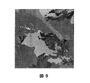
本発明の方法及び装置においては、るつぼの底、るつぼ枠の底板、及び/又は、るつぼ支持ブロックの内部の空隙を冷却剤が循環するが、この方法及び装置によって製造された結晶材料では、るつぼの下で冷却剤を循環させるために用いる空隙がない同様の方法及び装置を用いて製造された結晶材料と比べて、結晶の粒子径が著しく大きいことが分かっている。1つの例として、本発明の方法及び装置を用いて多結晶シリコンインゴットを調製し、比較例として、空隙又は循環する冷却剤を備えていない比較の方法を用いて多結晶シリコンインゴットを調製した。インゴットはワイヤソーで切断し、粒界は光学スキャナーを用いて、露出した断面の部分で確認した。得られた画像を図9(本発明の方法及び装置を用いて製造した多結晶シリコン)及び図10(比較の方法及び装置を用いて製造した多結晶シリコン)に示す。画像解析ソフトウェアを用いて粒子径を定量化し、分布を計算した。統計的な粒子径の分布を以下の表1及び図11のグラフで示す。 In the method and apparatus of the present invention, the coolant circulates through the bottom of the crucible, the bottom plate of the crucible frame, and / or the void inside the crucible support block. In the crystal material produced by this method and apparatus, the crucible It has been found that the crystal particle size is significantly larger compared to crystalline materials produced using similar methods and apparatus without voids used to circulate coolant underneath. As one example, a polycrystalline silicon ingot was prepared using the method and apparatus of the present invention, and as a comparative example, a polycrystalline silicon ingot was prepared using a comparative method without voids or circulating coolant. The ingot was cut with a wire saw, and the grain boundaries were confirmed on the exposed cross-section using an optical scanner. The obtained images are shown in FIG. 9 (polycrystalline silicon produced using the method and apparatus of the present invention) and FIG. 10 (polycrystalline silicon produced using the comparative method and apparatus). The particle size was quantified using image analysis software and the distribution was calculated. The statistical particle size distribution is shown in the following Table 1 and the graph of FIG.

データが示すとおり、本発明の方法により製造された多結晶シリコンインゴットの66.8%の平均粒子径が500mm2より大きい一方、比較の多結晶シリコンインゴットでは33%のみが同じ範囲の粒子径であった。したがって、著しく大きな粒子径を有する多結晶シリコンが、本発明の方法及び装置によって製造される。加えて、本発明の方法で製造された多結晶シリコンの結晶粒子は、シリコンインゴットの下から上まで実質的に柱状で、インゴットの上半分も下半分も粒子径が大きいことが明らかになっている。さらに、結果として生じる結晶粒子の配向は再現することが観察された。すなわち、同じ構成品に備えられた同じ空隙と共に同じ方法を用いると、同様の粒子径及び配向を有する結晶材料が製造された。結果として生じる結晶材料は、全体的に大きな粒子径を有するが、より優れた電気的及び構造的特性を備え、それによって太陽電池の性能が総合的に改善し、ウエハをより薄く切断できるようになると予想される。 As indicated by the data, whereas the average particle diameter 66.8 percent of the polycrystalline silicon ingot produced is greater than 500 mm 2 according to the method of the present invention, only 33% of polycrystalline silicon ingot comparison with the particle size of the same range there were. Thus, polycrystalline silicon having a significantly larger particle size is produced by the method and apparatus of the present invention. In addition, it is clear that the polycrystalline silicon crystal particles produced by the method of the present invention are substantially columnar from the bottom to the top of the silicon ingot, and that the upper and lower halves of the ingot have a large particle size. Yes. Furthermore, it was observed that the resulting crystal grain orientation was reproduced. That is, using the same method with the same voids provided in the same component, a crystalline material with similar particle size and orientation was produced. The resulting crystalline material has an overall large particle size, but with better electrical and structural properties, thereby improving the overall performance of the solar cell and allowing the wafer to be cut thinner. It is expected to be.
上記の本発明の好ましい実施形態は、説明及び記載の目的のために示したものである。本発明の内容を網羅するものではなく、開示されている形態に厳密に本発明を限定することも意図していない。変形例及び変更例は上記教示に鑑み可能であり、あるいは本発明の実施によっても習得可能である。検討している特定の利用にふさわしく、種々の実施形態において種々の変形例を用いて本発明を当業者が利用できるよう、本発明の原理及び実際の応用を説明するために、実施形態を選択し、説明した。本発明の範囲は、ここに添付する特許請求の範囲及びその均等物により規定するものである。 The preferred embodiments of the invention described above have been presented for purposes of illustration and description. It is not intended to be exhaustive or to limit the invention to the precise form disclosed. Variations and modifications are possible in light of the above teachings, or can be learned by practice of the invention. The embodiments are selected to illustrate the principles and practical applications of the present invention so that those skilled in the art can use the present invention with various variations in various embodiments, as appropriate for the particular application under consideration. And explained. The scope of the invention is defined by the claims appended hereto and their equivalents.
Claims (5)
前記高温帯内のるつぼ支持ブロックに隣接するるつぼ枠であって、前記るつぼ支持ブロックと熱的に接触している底板を有するるつぼ枠と、
前記るつぼ枠の底板と熱的に接触している底を有する前記るつぼ枠内に収められたるつぼ
を備える、結晶成長装置であって、
前記るつぼ支持ブロック、前記るつぼ枠の底板、又は前記るつぼ支持ブロックと前記るつぼ枠の底板の両方が、冷却剤を内部に有する少なくとも1つの空隙を備え、前記少なくとも1つの空隙はるつぼ枠の底板の中心又はるつぼの底の中心に隣接し、
前記空隙は入口及び出口を含み、これによって冷却剤は空隙に入り、空隙内を循環して、るつぼ枠の底板又はるつぼの底に直接熱的に接触し、空隙を出ることができる、
結晶成長装置。 A high temperature zone surrounded by thermal insulation,
A crucible frame adjacent to the crucible support block in the high temperature zone, the crucible frame having a bottom plate in thermal contact with the crucible support block;
A crucible housed within the crucible frame having a bottom in thermal contact with a bottom plate of the crucible frame.
A crystal growth apparatus comprising :
The crucible support block, the bottom plate of the crucible frame, or both of the bottom plate of the crucible frame and the crucible support block comprises at least one void having a cold却剤therein, a bottom plate of said at least one void crucible frame Adjacent to the center of the bottom of the crucible or the bottom of the crucible,
The void includes an inlet and an outlet, whereby the coolant enters the void, circulates within the void, and can be in direct thermal contact with the bottom plate of the crucible frame or the bottom of the crucible and exit the void.
Crystal growth equipment.
i)結晶成長装置の高温帯内のるつぼ支持ブロック上のるつぼ枠に含まれるるつぼを設置するステップであって、前記るつぼ枠が、前記るつぼ支持ブロックと熱的に接触している底板を有し、前記るつぼが、固体の原料を含み、前記るつぼ枠の底板と熱的に接触している底を有しているステップと、
ii)前記るつぼ内の前記固体の原料を加熱して、液状の原料溶融体を生成するステップと、
iii)前記るつぼ支持ブロック、前記るつぼ枠の底板、又は前記るつぼ支持ブロックと前記るつぼ枠の底板の両方の内部の少なくとも1つの空隙に少なくとも1種類の冷却剤を循環させるステップであって、前記少なくとも1つの空隙はるつぼ枠の底板の中心又はるつぼの底の中心に隣接し、前記冷却剤は入口から空隙に入り、空隙内を循環して、るつぼ枠の底板又はるつぼの底に直接熱的に接触し、出口から空隙を出るステップと、
iv)前記高温帯から熱を除去して、前記結晶材料を生成するステップと
を備える、方法。 A method for producing a crystalline material comprising:
i) installing a crucible contained in a crucible frame on a crucible support block in a high temperature zone of the crystal growth apparatus, the crucible frame having a bottom plate in thermal contact with the crucible support block The crucible includes a solid raw material and has a bottom in thermal contact with a bottom plate of the crucible frame;
ii) heating the solid raw material in the crucible to produce a liquid raw material melt;
iii) circulating at least one coolant in the crucible support block, the bottom plate of the crucible frame, or at least one void inside both the crucible support block and the bottom plate of the crucible frame, the step comprising: One gap is adjacent to the center of the bottom plate of the crucible frame or the center of the bottom of the crucible, and the coolant enters the gap from the inlet and circulates in the gap to directly heat the bottom plate of the crucible frame or the bottom of the crucible. Contacting and exiting the void from the outlet ;
iv) removing heat from the high temperature zone to produce the crystalline material.
Applications Claiming Priority (3)
| Application Number | Priority Date | Filing Date | Title |
|---|---|---|---|
| US13/098,989 US20120280429A1 (en) | 2011-05-02 | 2011-05-02 | Apparatus and method for producing a multicrystalline material having large grain sizes |
| US13/098,989 | 2011-05-02 | ||
| PCT/US2012/035803 WO2012151155A2 (en) | 2011-05-02 | 2012-04-30 | Apparatus and method for producing a multicrystalline material having large grain sizes |
Publications (3)
| Publication Number | Publication Date |
|---|---|
| JP2014521577A JP2014521577A (en) | 2014-08-28 |
| JP2014521577A5 JP2014521577A5 (en) | 2015-04-30 |
| JP5953368B2 true JP5953368B2 (en) | 2016-07-20 |
Family
ID=47089731
Family Applications (1)
| Application Number | Title | Priority Date | Filing Date |
|---|---|---|---|
| JP2014509339A Expired - Fee Related JP5953368B2 (en) | 2011-05-02 | 2012-04-30 | Apparatus and method for producing polycrystalline material having large particle size |
Country Status (7)
| Country | Link |
|---|---|
| US (1) | US20120280429A1 (en) |
| EP (1) | EP2705177A4 (en) |
| JP (1) | JP5953368B2 (en) |
| KR (1) | KR20140044809A (en) |
| CN (1) | CN103703169A (en) |
| TW (1) | TWI547603B (en) |
| WO (1) | WO2012151155A2 (en) |
Families Citing this family (7)
| Publication number | Priority date | Publication date | Assignee | Title |
|---|---|---|---|---|
| TWI441962B (en) * | 2011-10-14 | 2014-06-21 | Sino American Silicon Prod Inc | Crystalline silicon ingot and method of fabricating the same |
| CN103184516B (en) * | 2013-03-25 | 2015-07-01 | 湖南红太阳光电科技有限公司 | Polysilicon ingot casting thermal-field structure and method capable of reducing shadows and hard spots |
| CN103233264A (en) * | 2013-05-03 | 2013-08-07 | 江苏海翔化工有限公司 | Silicon material melting heating process capable of preventing silicon leakage in quartz crucible in Czochralski method |
| CN103469293B (en) * | 2013-09-02 | 2015-10-28 | 湖南红太阳光电科技有限公司 | A kind of preparation method of polysilicon |
| US10415151B1 (en) | 2014-03-27 | 2019-09-17 | Varian Semiconductor Equipment Associates, Inc | Apparatus for controlling heat flow within a silicon melt |
| KR102477163B1 (en) * | 2018-02-23 | 2022-12-14 | 오씨아이 주식회사 | Apparatus for growing crystal and driving method thereof |
| US11127572B2 (en) | 2018-08-07 | 2021-09-21 | Silfex, Inc. | L-shaped plasma confinement ring for plasma chambers |
Family Cites Families (22)
| Publication number | Priority date | Publication date | Assignee | Title |
|---|---|---|---|---|
| JP2897963B2 (en) * | 1992-05-15 | 1999-05-31 | 信越石英株式会社 | Vertical heat treatment equipment and heat insulator |
| JP3368113B2 (en) * | 1995-09-05 | 2003-01-20 | シャープ株式会社 | Manufacturing method of polycrystalline semiconductor |
| JPH09100199A (en) * | 1995-10-02 | 1997-04-15 | Kyocera Corp | Production of rutile single crystal |
| JPH09255484A (en) * | 1996-03-26 | 1997-09-30 | Sumitomo Sitix Corp | Supporting member for crucible for pulling single crystal |
| JPH10139580A (en) * | 1996-11-13 | 1998-05-26 | Japan Steel Works Ltd:The | Production of unidirectionally solidified material and unidirectional solidifying device |
| JP3520957B2 (en) * | 1997-06-23 | 2004-04-19 | シャープ株式会社 | Method and apparatus for manufacturing polycrystalline semiconductor ingot |
| JPH11310496A (en) * | 1998-02-25 | 1999-11-09 | Mitsubishi Materials Corp | Production of silicon ingot having unidirectionally solidified texture and apparatus therefor |
| JP3964070B2 (en) * | 1999-04-08 | 2007-08-22 | 三菱マテリアルテクノ株式会社 | Crystalline silicon production equipment |
| TWI265198B (en) * | 2002-12-02 | 2006-11-01 | Univ Nat Taiwan | The method and equipments for controlling the solidification of alloys in induction melting using cold crucible |
| JP2005162507A (en) * | 2003-11-28 | 2005-06-23 | Sharp Corp | Polycrystal semiconductor ingot and its manufacturing device and method |
| JP2005289776A (en) * | 2004-04-05 | 2005-10-20 | Canon Inc | Method for manufacturing crystal and crystal manufacturing apparatus |
| JP2006308267A (en) * | 2005-05-02 | 2006-11-09 | Iis Materials:Kk | Crucible device and solidifying method of molten material using the same |
| JP2007197274A (en) * | 2006-01-27 | 2007-08-09 | Toyota Motor Corp | Method for manufacturing silicon carbide single crystal |
| KR100955221B1 (en) * | 2007-10-05 | 2010-04-29 | 주식회사 글로실 | Apparatus for manufacturing poly crystaline silicon ingot for solar battery having door open/close device using hinge |
| US20090159244A1 (en) * | 2007-12-19 | 2009-06-25 | Stephen Mounioloux | Water-cooled cold plate with integrated pump |
| JP5002522B2 (en) * | 2008-04-24 | 2012-08-15 | 株式会社日立製作所 | Cooling device for electronic equipment and electronic equipment provided with the same |
| JP2009298652A (en) * | 2008-06-13 | 2009-12-24 | Sumco Corp | Graphite crucible and method for preventing deformation of quartz crucible using graphite crucible |
| JP2011524332A (en) * | 2008-06-16 | 2011-09-01 | ジーティー・ソーラー・インコーポレーテッド | System and method for growing single crystal silicon ingots by directional solidification |
| CN101624723B (en) * | 2008-07-10 | 2012-06-06 | 昆山中辰矽晶有限公司 | Mode and device for forming crystal |
| KR20100024675A (en) * | 2008-08-26 | 2010-03-08 | 주식회사 아바코 | Manufacturing equipment for ingot and method of manufacturing the ingot |
| TW201012988A (en) * | 2008-08-27 | 2010-04-01 | Bp Corp North America Inc | Gas recirculation heat exchanger for casting silicon |
| DE102008051492A1 (en) * | 2008-10-13 | 2010-04-15 | Pva Tepla Ag | Device for crystallizing non-ferrous metals |
-
2011
- 2011-05-02 US US13/098,989 patent/US20120280429A1/en not_active Abandoned
-
2012
- 2012-04-30 CN CN201280032882.9A patent/CN103703169A/en active Pending
- 2012-04-30 EP EP12779465.9A patent/EP2705177A4/en not_active Withdrawn
- 2012-04-30 KR KR1020137031928A patent/KR20140044809A/en not_active Application Discontinuation
- 2012-04-30 WO PCT/US2012/035803 patent/WO2012151155A2/en active Application Filing
- 2012-04-30 JP JP2014509339A patent/JP5953368B2/en not_active Expired - Fee Related
- 2012-05-02 TW TW101115531A patent/TWI547603B/en not_active IP Right Cessation
Also Published As
| Publication number | Publication date |
|---|---|
| KR20140044809A (en) | 2014-04-15 |
| WO2012151155A3 (en) | 2013-03-21 |
| US20120280429A1 (en) | 2012-11-08 |
| EP2705177A2 (en) | 2014-03-12 |
| CN103703169A (en) | 2014-04-02 |
| JP2014521577A (en) | 2014-08-28 |
| WO2012151155A2 (en) | 2012-11-08 |
| TWI547603B (en) | 2016-09-01 |
| EP2705177A4 (en) | 2014-10-01 |
| TW201311949A (en) | 2013-03-16 |
Similar Documents
| Publication | Publication Date | Title |
|---|---|---|
| JP5953368B2 (en) | Apparatus and method for producing polycrystalline material having large particle size | |
| TWI363109B (en) | ||
| JP2017149641A (en) | Liquid-cooled heat exchanger | |
| JPH11310496A (en) | Production of silicon ingot having unidirectionally solidified texture and apparatus therefor | |
| TWI412640B (en) | High-throughput apparatus for manufacturing silicon ingots for polycrystalline silicon solar cell | |
| US20150086464A1 (en) | Method of producing monocrystalline silicon | |
| TW201012988A (en) | Gas recirculation heat exchanger for casting silicon | |
| KR100778019B1 (en) | A crucible for an electromagnetic continuous casting apparatus with high melting efficiency and product yield | |
| CN103966657B (en) | Ingotting furnace for polycrystalline silicon and quasi single crystal silicon and application method for ingotting furnace | |
| CN105862124A (en) | Apparatus and methods for producing silicon-ingots | |
| WO1993017158A1 (en) | Method and apparatus for growing shaped crystals | |
| CN105887186A (en) | Silicon single-crystal pulling equipment and growing method | |
| JPS646130B2 (en) | ||
| JP4664967B2 (en) | Silicon casting apparatus and silicon substrate manufacturing method | |
| JP2013112581A (en) | Crucible, production method of polycrystalline silicon ingot, polycrystalline silicon ingot, polycrystalline silicon wafer, polycrystalline silicon solar cell, and polycrystalline solar cell module | |
| WO2012111850A1 (en) | Polycrystalline wafer, method for producing same and method for casting polycrystalline material | |
| WO2013095928A1 (en) | Method of producing bricks from a silicon ingot | |
| CN102438773A (en) | Process for producing multicrystalline silicon ingots by the induction method and apparatus for carrying out the same | |
| JP2016124713A (en) | Method of producing polycrystalline silicon ingot | |
| CN102912416A (en) | Novel polycrystalline furnace heating device | |
| JP5449645B2 (en) | A method of manufacturing a silicon plate for heat treatment. | |
| CN110387579A (en) | A kind of method and casting single crystal silicon ingot using octagon ingot casting thermal field casting single crystal | |
| CN103352248B (en) | Crystallization process of polycrystalline silicon and ingot casting process of polycrystalline silicon | |
| WO2013019399A2 (en) | Method for producing a monocrystalline product | |
| CN102925960A (en) | Method for reducing central defects of silicon ingots and ingot casting furnace using same |
Legal Events
| Date | Code | Title | Description |
|---|---|---|---|
| A521 | Written amendment |
Free format text: JAPANESE INTERMEDIATE CODE: A523 Effective date: 20150312 |
|
| A621 | Written request for application examination |
Free format text: JAPANESE INTERMEDIATE CODE: A621 Effective date: 20150312 |
|
| A977 | Report on retrieval |
Free format text: JAPANESE INTERMEDIATE CODE: A971007 Effective date: 20150828 |
|
| A131 | Notification of reasons for refusal |
Free format text: JAPANESE INTERMEDIATE CODE: A131 Effective date: 20150930 |
|
| A521 | Written amendment |
Free format text: JAPANESE INTERMEDIATE CODE: A523 Effective date: 20151224 |
|
| TRDD | Decision of grant or rejection written | ||
| A01 | Written decision to grant a patent or to grant a registration (utility model) |
Free format text: JAPANESE INTERMEDIATE CODE: A01 Effective date: 20160516 |
|
| A61 | First payment of annual fees (during grant procedure) |
Free format text: JAPANESE INTERMEDIATE CODE: A61 Effective date: 20160613 |
|
| R150 | Certificate of patent or registration of utility model |
Ref document number: 5953368 Country of ref document: JP Free format text: JAPANESE INTERMEDIATE CODE: R150 |
|
| R250 | Receipt of annual fees |
Free format text: JAPANESE INTERMEDIATE CODE: R250 |
|
| LAPS | Cancellation because of no payment of annual fees |