JP2010007893A - 沸騰冷却装置 - Google Patents
沸騰冷却装置 Download PDFInfo
- Publication number
- JP2010007893A JP2010007893A JP2008164712A JP2008164712A JP2010007893A JP 2010007893 A JP2010007893 A JP 2010007893A JP 2008164712 A JP2008164712 A JP 2008164712A JP 2008164712 A JP2008164712 A JP 2008164712A JP 2010007893 A JP2010007893 A JP 2010007893A
- Authority
- JP
- Japan
- Prior art keywords
- heat receiving
- receiving surface
- heat
- partition
- heating element
- Prior art date
- Legal status (The legal status is an assumption and is not a legal conclusion. Google has not performed a legal analysis and makes no representation as to the accuracy of the status listed.)
- Granted
Links
- 238000001816 cooling Methods 0.000 title claims abstract description 53
- 238000005192 partition Methods 0.000 claims abstract description 101
- 238000010438 heat treatment Methods 0.000 claims abstract description 76
- 238000009835 boiling Methods 0.000 claims abstract description 70
- 239000003507 refrigerant Substances 0.000 claims abstract description 65
- 239000007788 liquid Substances 0.000 claims abstract description 26
- 238000000638 solvent extraction Methods 0.000 claims abstract description 12
- 230000004888 barrier function Effects 0.000 description 7
- 230000001133 acceleration Effects 0.000 description 2
- 230000005494 condensation Effects 0.000 description 2
- 238000009833 condensation Methods 0.000 description 2
- 230000007423 decrease Effects 0.000 description 2
- 230000002349 favourable effect Effects 0.000 description 2
- 230000017525 heat dissipation Effects 0.000 description 2
- 239000002184 metal Substances 0.000 description 2
- 239000004065 semiconductor Substances 0.000 description 2
- 238000009825 accumulation Methods 0.000 description 1
- 238000004581 coalescence Methods 0.000 description 1
- 239000002826 coolant Substances 0.000 description 1
- 239000000498 cooling water Substances 0.000 description 1
- 230000006866 deterioration Effects 0.000 description 1
- 230000000694 effects Effects 0.000 description 1
- 230000005484 gravity Effects 0.000 description 1
- 238000007654 immersion Methods 0.000 description 1
- 238000000034 method Methods 0.000 description 1
- 230000005855 radiation Effects 0.000 description 1
- 230000008016 vaporization Effects 0.000 description 1
- XLYOFNOQVPJJNP-UHFFFAOYSA-N water Substances O XLYOFNOQVPJJNP-UHFFFAOYSA-N 0.000 description 1
Images


Classifications
-
- F—MECHANICAL ENGINEERING; LIGHTING; HEATING; WEAPONS; BLASTING
- F28—HEAT EXCHANGE IN GENERAL
- F28D—HEAT-EXCHANGE APPARATUS, NOT PROVIDED FOR IN ANOTHER SUBCLASS, IN WHICH THE HEAT-EXCHANGE MEDIA DO NOT COME INTO DIRECT CONTACT
- F28D15/00—Heat-exchange apparatus with the intermediate heat-transfer medium in closed tubes passing into or through the conduit walls ; Heat-exchange apparatus employing intermediate heat-transfer medium or bodies
- F28D15/02—Heat-exchange apparatus with the intermediate heat-transfer medium in closed tubes passing into or through the conduit walls ; Heat-exchange apparatus employing intermediate heat-transfer medium or bodies in which the medium condenses and evaporates, e.g. heat pipes
- F28D15/0266—Heat-exchange apparatus with the intermediate heat-transfer medium in closed tubes passing into or through the conduit walls ; Heat-exchange apparatus employing intermediate heat-transfer medium or bodies in which the medium condenses and evaporates, e.g. heat pipes with separate evaporating and condensing chambers connected by at least one conduit; Loop-type heat pipes; with multiple or common evaporating or condensing chambers
-
- F—MECHANICAL ENGINEERING; LIGHTING; HEATING; WEAPONS; BLASTING
- F28—HEAT EXCHANGE IN GENERAL
- F28F—DETAILS OF HEAT-EXCHANGE AND HEAT-TRANSFER APPARATUS, OF GENERAL APPLICATION
- F28F13/00—Arrangements for modifying heat-transfer, e.g. increasing, decreasing
- F28F13/06—Arrangements for modifying heat-transfer, e.g. increasing, decreasing by affecting the pattern of flow of the heat-exchange media
Landscapes
- Engineering & Computer Science (AREA)
- Physics & Mathematics (AREA)
- Thermal Sciences (AREA)
- Mechanical Engineering (AREA)
- General Engineering & Computer Science (AREA)
- Life Sciences & Earth Sciences (AREA)
- Sustainable Development (AREA)
- Cooling Or The Like Of Electrical Apparatus (AREA)
Abstract
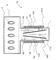
【解決手段】本発明の沸騰冷却装置10は、上下方向に延在し発熱体Zの熱を液体冷媒が受熱する受熱面50を有し、内部に液体冷媒を収容する収容部1を備え、収容部1は、液体冷媒が下方から上方に向かって流れると共に、受熱面50が配置される受熱通路100と、液体冷媒が供給される供給通路110と、収容部1の内部空間を受熱通路100と供給通路110とに仕切る仕切部400と、を有する沸騰冷却装置であって、仕切部400の受熱面50と対向する面と受熱面50との間隙は上方側が拡幅されていることを特徴とする。
【選択図】図1
Description
(第1実施形態)
第1実施形態では沸騰冷却装置10を例に挙げる。以下、沸騰冷却装置10について図1を参照して説明する。図1は、沸騰冷却装置10の模式断面図である。
内底面上に落ちた冷媒も、その後収容部1に流入する。
第2実施形態では沸騰冷却装置11を例に挙げる。以下、沸騰冷却装置11について図2を参照して説明する。図2は、沸騰冷却装置11の模式断面図である。沸騰冷却装置11は、仕切部401の形状が異なるだけで後は第1実施形態で説明した沸騰冷却装置10と同様のものである。そのため第1実施形態で説明したものと同じものは説明を省略し、異なる部分を以下に説明する。
第3実施形態では沸騰冷却装置12を例に挙げる。以下、沸騰冷却装置12について図3を参照して説明する。図3は、沸騰冷却装置12の模式断面図である。沸騰冷却装置12は、第1発熱体Z1及び第2発熱体Z2が収容部1の相対する側壁面に各々取り付けられている。
第4実施形態では沸騰冷却装置13を例に挙げる。以下、沸騰冷却装置13について図4を参照して説明する。図4は、沸騰冷却装置13の模式断面図である。沸騰冷却装置13は、第3発熱体Z11及び第4発熱体Z12が収容部1の一方の側壁面に上下に間隔をあけて各々取り付けられており、第5発熱体Z21及び第6発熱体Z22が収容部1の他方の側壁面に上下に間隔をあけて各々取り付けられている。
100:受熱通路、110:供給通路、400:仕切部、Z:発熱体
Claims (5)
- 上下方向に延在し発熱体の熱を液体冷媒が受熱する受熱面を有し、内部に液体冷媒を収容する収容部を備え、
前記収容部は、前記液体冷媒が下方から上方に向かって流れると共に、前記受熱面が配置される受熱通路と、前記液体冷媒が供給される供給通路と、前記収容部の内部空間を前記受熱通路と前記供給通路とに仕切る仕切部と、を有する沸騰冷却装置であって、
前記仕切部の前記受熱面と対向する面と前記受熱面との間隙は上方側が拡幅されていることを特徴とする沸騰冷却装置。 - 前記仕切部の前記受熱面と対向する面は前記受熱面との間隙が上方側において拡幅するように傾斜している請求項1に記載の沸騰冷却装置。
- 前記発熱体は前記収容部の一方の側壁部に取り付けられた第1発熱体と、対向する他方の側壁部に取り付けられた第2発熱体とからなり、
前記収容部は、第1発熱体の熱を液体冷媒が受熱する第1受熱面と前記供給通路とを仕切る第1仕切部と、第2発熱体の熱を液体冷媒が受熱する第2受熱面と前記供給通路とを仕切る第2仕切部とを有し、
前記第1仕切部の前記第1受熱面と対向する面と前記第1受熱面との間隙及び前記第2仕切部の前記第2受熱面と対向する面と前記第2受熱面との間隙は共に上方側が拡幅されている請求項1または2に記載の沸騰冷却装置。 - 前記発熱体は前記収容部の側壁部に上下方向に複数取り付けられている請求項1〜3の何れか一項に記載の沸騰冷却装置。
- 前記仕切部の前記受熱面と対向する面と前記受熱面との間隙が幅5mm以下である請求項1〜4の何れか一項に記載の沸騰冷却装置。
Priority Applications (1)
| Application Number | Priority Date | Filing Date | Title |
|---|---|---|---|
| JP2008164712A JP5092931B2 (ja) | 2008-06-24 | 2008-06-24 | 沸騰冷却装置 |
Applications Claiming Priority (1)
| Application Number | Priority Date | Filing Date | Title |
|---|---|---|---|
| JP2008164712A JP5092931B2 (ja) | 2008-06-24 | 2008-06-24 | 沸騰冷却装置 |
Publications (2)
| Publication Number | Publication Date |
|---|---|
| JP2010007893A true JP2010007893A (ja) | 2010-01-14 |
| JP5092931B2 JP5092931B2 (ja) | 2012-12-05 |
Family
ID=41588619
Family Applications (1)
| Application Number | Title | Priority Date | Filing Date |
|---|---|---|---|
| JP2008164712A Expired - Fee Related JP5092931B2 (ja) | 2008-06-24 | 2008-06-24 | 沸騰冷却装置 |
Country Status (1)
| Country | Link |
|---|---|
| JP (1) | JP5092931B2 (ja) |
Cited By (5)
| Publication number | Priority date | Publication date | Assignee | Title |
|---|---|---|---|---|
| WO2010095373A1 (ja) * | 2009-02-23 | 2010-08-26 | 株式会社豊田自動織機 | 沸騰冷却装置 |
| WO2012161002A1 (ja) * | 2011-05-20 | 2012-11-29 | 日本電気株式会社 | 平板型冷却装置及びその使用方法 |
| JP2013069740A (ja) * | 2011-09-21 | 2013-04-18 | Nec Corp | 平板型冷却装置及びその使用方法 |
| US11467637B2 (en) | 2018-07-31 | 2022-10-11 | Wuxi Kalannipu Thermal Management Technology Co., Ltd. | Modular computer cooling system |
| US11606880B2 (en) | 2016-03-03 | 2023-03-14 | Wuxi Kalannipu Thermal Management Technology Co., Ltd. | Self-organizing thermodynamic system |
Citations (2)
| Publication number | Priority date | Publication date | Assignee | Title |
|---|---|---|---|---|
| JPS61121373U (ja) * | 1985-01-09 | 1986-07-31 | ||
| JPH10173115A (ja) * | 1996-12-06 | 1998-06-26 | Toshiba Corp | 沸騰冷却装置及びその製造方法 |
-
2008
- 2008-06-24 JP JP2008164712A patent/JP5092931B2/ja not_active Expired - Fee Related
Patent Citations (2)
| Publication number | Priority date | Publication date | Assignee | Title |
|---|---|---|---|---|
| JPS61121373U (ja) * | 1985-01-09 | 1986-07-31 | ||
| JPH10173115A (ja) * | 1996-12-06 | 1998-06-26 | Toshiba Corp | 沸騰冷却装置及びその製造方法 |
Cited By (6)
| Publication number | Priority date | Publication date | Assignee | Title |
|---|---|---|---|---|
| WO2010095373A1 (ja) * | 2009-02-23 | 2010-08-26 | 株式会社豊田自動織機 | 沸騰冷却装置 |
| WO2012161002A1 (ja) * | 2011-05-20 | 2012-11-29 | 日本電気株式会社 | 平板型冷却装置及びその使用方法 |
| JPWO2012161002A1 (ja) * | 2011-05-20 | 2014-07-31 | 日本電気株式会社 | 平板型冷却装置及びその使用方法 |
| JP2013069740A (ja) * | 2011-09-21 | 2013-04-18 | Nec Corp | 平板型冷却装置及びその使用方法 |
| US11606880B2 (en) | 2016-03-03 | 2023-03-14 | Wuxi Kalannipu Thermal Management Technology Co., Ltd. | Self-organizing thermodynamic system |
| US11467637B2 (en) | 2018-07-31 | 2022-10-11 | Wuxi Kalannipu Thermal Management Technology Co., Ltd. | Modular computer cooling system |
Also Published As
| Publication number | Publication date |
|---|---|
| JP5092931B2 (ja) | 2012-12-05 |
Similar Documents
| Publication | Publication Date | Title |
|---|---|---|
| JP6015675B2 (ja) | 冷却装置及びそれを用いた電子機器 | |
| US20140318167A1 (en) | Evaporator, cooling device, and electronic apparatus | |
| JP6137167B2 (ja) | 冷却装置および冷却システム | |
| JP6358872B2 (ja) | 発熱素子用沸騰冷却器 | |
| US20110000649A1 (en) | Heat sink device | |
| US20140165638A1 (en) | Cooling device and electronic device made therewith | |
| US9921003B2 (en) | Wickless heat pipe and thermal ground plane | |
| JPH0878588A (ja) | 沸騰冷却装置 | |
| CN102832185A (zh) | 沸腾冷却系统 | |
| CN105940279A (zh) | 冷却装置和具有它的数据中心 | |
| JP5092931B2 (ja) | 沸騰冷却装置 | |
| JP6505130B2 (ja) | 冷却器 | |
| JP2010080507A (ja) | 電子装置 | |
| US11754344B2 (en) | Boiling cooler | |
| US20180249596A1 (en) | Cooler, power conversion apparatus, and cooling system | |
| JP2010236792A (ja) | 沸騰冷却装置 | |
| JP2021188890A (ja) | 伝熱部材および伝熱部材を有する冷却デバイス | |
| JP2009135142A (ja) | 沸騰冷却装置 | |
| JP2013033807A (ja) | 冷却装置およびそれを用いた電子機器 | |
| JP2009150575A (ja) | 沸騰冷却装置 | |
| JP5860728B2 (ja) | 電子機器の冷却システム | |
| JP2024179763A (ja) | 沸騰冷却装置 | |
| KR101297046B1 (ko) | 베이퍼 핀을 구비하는 상변화 열전달 장치 | |
| JP5163548B2 (ja) | 沸騰冷却装置 | |
| JP6127983B2 (ja) | 冷却構造及びそれを用いた電子装置 |
Legal Events
| Date | Code | Title | Description |
|---|---|---|---|
| A621 | Written request for application examination |
Free format text: JAPANESE INTERMEDIATE CODE: A621 Effective date: 20100729 |
|
| A977 | Report on retrieval |
Free format text: JAPANESE INTERMEDIATE CODE: A971007 Effective date: 20111221 |
|
| A131 | Notification of reasons for refusal |
Free format text: JAPANESE INTERMEDIATE CODE: A131 Effective date: 20120110 |
|
| A521 | Written amendment |
Free format text: JAPANESE INTERMEDIATE CODE: A523 Effective date: 20120305 |
|
| TRDD | Decision of grant or rejection written | ||
| A01 | Written decision to grant a patent or to grant a registration (utility model) |
Free format text: JAPANESE INTERMEDIATE CODE: A01 Effective date: 20120821 |
|
| A01 | Written decision to grant a patent or to grant a registration (utility model) |
Free format text: JAPANESE INTERMEDIATE CODE: A01 |
|
| A61 | First payment of annual fees (during grant procedure) |
Free format text: JAPANESE INTERMEDIATE CODE: A61 Effective date: 20120903 |
|
| FPAY | Renewal fee payment (prs date is renewal date of database) |
Free format text: PAYMENT UNTIL: 20150928 Year of fee payment: 3 |
|
| LAPS | Cancellation because of no payment of annual fees |