JP2010007893A - Evaporative cooling device - Google Patents
Evaporative cooling device Download PDFInfo
- Publication number
- JP2010007893A JP2010007893A JP2008164712A JP2008164712A JP2010007893A JP 2010007893 A JP2010007893 A JP 2010007893A JP 2008164712 A JP2008164712 A JP 2008164712A JP 2008164712 A JP2008164712 A JP 2008164712A JP 2010007893 A JP2010007893 A JP 2010007893A
- Authority
- JP
- Japan
- Prior art keywords
- heat receiving
- receiving surface
- heat
- partition
- heating element
- Prior art date
- Legal status (The legal status is an assumption and is not a legal conclusion. Google has not performed a legal analysis and makes no representation as to the accuracy of the status listed.)
- Granted
Links
Images


Classifications
-
- F—MECHANICAL ENGINEERING; LIGHTING; HEATING; WEAPONS; BLASTING
- F28—HEAT EXCHANGE IN GENERAL
- F28D—HEAT-EXCHANGE APPARATUS, NOT PROVIDED FOR IN ANOTHER SUBCLASS, IN WHICH THE HEAT-EXCHANGE MEDIA DO NOT COME INTO DIRECT CONTACT
- F28D15/00—Heat-exchange apparatus with the intermediate heat-transfer medium in closed tubes passing into or through the conduit walls ; Heat-exchange apparatus employing intermediate heat-transfer medium or bodies
- F28D15/02—Heat-exchange apparatus with the intermediate heat-transfer medium in closed tubes passing into or through the conduit walls ; Heat-exchange apparatus employing intermediate heat-transfer medium or bodies in which the medium condenses and evaporates, e.g. heat pipes
- F28D15/0266—Heat-exchange apparatus with the intermediate heat-transfer medium in closed tubes passing into or through the conduit walls ; Heat-exchange apparatus employing intermediate heat-transfer medium or bodies in which the medium condenses and evaporates, e.g. heat pipes with separate evaporating and condensing chambers connected by at least one conduit; Loop-type heat pipes; with multiple or common evaporating or condensing chambers
-
- F—MECHANICAL ENGINEERING; LIGHTING; HEATING; WEAPONS; BLASTING
- F28—HEAT EXCHANGE IN GENERAL
- F28F—DETAILS OF HEAT-EXCHANGE AND HEAT-TRANSFER APPARATUS, OF GENERAL APPLICATION
- F28F13/00—Arrangements for modifying heat-transfer, e.g. increasing, decreasing
- F28F13/06—Arrangements for modifying heat-transfer, e.g. increasing, decreasing by affecting the pattern of flow of the heat-exchange media
Landscapes
- Engineering & Computer Science (AREA)
- Physics & Mathematics (AREA)
- Thermal Sciences (AREA)
- Mechanical Engineering (AREA)
- General Engineering & Computer Science (AREA)
- Life Sciences & Earth Sciences (AREA)
- Sustainable Development (AREA)
- Cooling Or The Like Of Electrical Apparatus (AREA)
Abstract
Description
本発明は、冷媒を用いた沸騰冷却装置に関するものである。 The present invention relates to a boiling cooling device using a refrigerant.
沸騰冷却装置は、液体冷媒が沸騰する際の潜熱を利用して発熱体を冷却する装置である。例えば、特開2003−42672号公報(特許文献1)に開示された沸騰冷却装置では、内部に冷媒を貯留し一方表面に発熱体が取り付けられる冷媒容器と、冷媒容器の他方表面に組付けられた放熱部とを備えている。さらに、この沸騰冷却装置は、冷媒容器内を発熱体側流路と放熱部側流路とに仕切る障壁部を備えている。沸騰冷却装置は、冷媒容器の両表面が直立した状態で使用されることを前提として、良好な冷媒循環を実現している。 The boiling cooling device is a device that cools a heating element using latent heat when a liquid refrigerant boils. For example, in a boiling cooling device disclosed in Japanese Patent Application Laid-Open No. 2003-42672 (Patent Document 1), a refrigerant container that stores a refrigerant therein and a heating element is attached to one surface thereof is assembled to the other surface of the refrigerant container. And a heat dissipation part. Further, the boiling cooling device includes a barrier section that partitions the inside of the refrigerant container into a heating element side flow path and a heat radiation section side flow path. The boiling cooling device realizes good refrigerant circulation on the assumption that both surfaces of the refrigerant container are used in an upright state.
また特開平8−29041号公報(特許文献2)に開示された沸騰冷却装置では、障壁部はなく、冷却容器の幅を上部に行くほど幅広にする構造を備えている。冷却容器の幅が上部にいくほど幅広となっているため発生した気泡が上部の発熱体により発生した気泡と干渉することがないとされている。
沸騰冷却装置では、沸騰伝熱を利用して冷却を行っている。沸騰伝熱は、図5に示すように、受熱面500と障壁部600との感覚が狭いと(例えば1mm〜5mm程度)、沸騰熱伝導が向上することが確認されている。それは、障壁部600により一時的に気泡700が保持され、その保持された気泡700と受熱面500との間のマイクロレイヤー900という部分における熱の移動が良好であるため、沸騰熱伝導が向上すると推測されている。しかし冷媒が沸騰することによって出来た気泡700が上部の受熱面500に溜まると、上部の気泡700が多すぎ、受熱面500の伝熱不良が起こる。
In the boiling cooling device, cooling is performed using boiling heat transfer. As shown in FIG. 5, boiling heat transfer has been confirmed to improve boiling heat conduction when the sense of the
特許文献1に記載の沸騰冷却装置は、障壁部を設けているが、それは発熱体側流路と放熱部側流路を分けるために設けられただけであって、受熱面と障壁部との距離を小さくすることで沸騰伝熱を向上させるものではない。 The boiling cooling device described in Patent Document 1 is provided with a barrier portion, which is provided only to separate the heating element side flow path and the heat dissipation section side flow path, and the distance between the heat receiving surface and the barrier section. It is not intended to improve the boiling heat transfer by reducing.
また特許文献2では、気泡の干渉を抑えるために冷媒容器の幅を上部に行くほど幅広にしているが、単に気泡が充満しないようにするために上部の幅を広くするという発想しか開示されておらず、受熱面と障壁部との距離をどの程度にするのが良いのかという開示はない。
Further, in
本発明は、このような事情に鑑みてなされたものであり、良好な沸騰伝熱が行われる沸騰冷却装置を提供することを目的とする。 This invention is made | formed in view of such a situation, and it aims at providing the boiling cooling device in which favorable boiling heat transfer is performed.
本発明の沸騰冷却装置は、上下方向に延在し発熱体の熱を液体冷媒が受熱する受熱面を有し、内部に液体冷媒を収容する収容部を備え、収容部は、液体冷媒が下方から上方に向かって流れると共に、受熱面が配置される受熱通路と、液体冷媒が供給される供給通路と、収容部の内部空間を受熱通路と供給通路とに仕切る仕切部と、を有する沸騰冷却装置であって、仕切部の受熱面と対向する面と受熱面との間隙は上方側が拡幅されていることを特徴とする。 The boiling cooling device of the present invention has a heat receiving surface that extends in the vertical direction and receives the heat of the heating element by the liquid refrigerant, and includes an accommodating portion that accommodates the liquid refrigerant therein. And boil cooling having a heat receiving passage in which the heat receiving surface is disposed, a supply passage to which liquid refrigerant is supplied, and a partition that partitions the internal space of the housing portion into the heat receiving passage and the supply passage. It is an apparatus, Comprising: The upper side is widened by the clearance gap between the surface facing the heat receiving surface of a partition part, and a heat receiving surface, It is characterized by the above-mentioned.
発熱体の発熱によって、受熱通路の冷媒が沸騰し気泡が発生する。受熱面の下方部側で発生した気泡は冷媒中を上部に向かって上昇していく。本発明の沸騰冷却装置は収容部に仕切部を有し、かつ仕切部の受熱面と対向する面と受熱面との間隙は上方側が拡幅されているため、下方部側で発生した気泡が上方部側で発生した気泡と合体するのを抑制出来、そのため受熱面の上部と冷媒との熱伝導が悪くなることを抑制できる。また気泡の浮力と気泡成長によって冷媒の流れが形成されるのを利用し、冷媒中に仕切部に沿って受熱通路−供給通路−受熱通路の一方向へ流れる自然対流による冷媒の流路を形成することが出来る。 Due to the heat generated by the heating element, the refrigerant in the heat receiving passage boils and bubbles are generated. Bubbles generated on the lower side of the heat receiving surface rise upward in the refrigerant. The boiling cooling device of the present invention has a partition portion in the housing portion, and the gap between the surface facing the heat receiving surface of the partition portion and the heat receiving surface is widened on the upper side. It is possible to suppress coalescence with bubbles generated on the part side, and therefore, it is possible to suppress deterioration of heat conduction between the upper portion of the heat receiving surface and the refrigerant. In addition, by utilizing the fact that the flow of the refrigerant is formed by bubble buoyancy and bubble growth, a refrigerant flow path is formed in the refrigerant by natural convection flowing in one direction along the partitioning section along the heat receiving passage, the supply passage, and the heat receiving passage. I can do it.
このような冷媒の流路を形成出来ることによって発熱体の上方、下方にかかわらず発熱体全体の伝熱の促進を図ることが出来る。これにより、良好な冷媒循環を実現できる。 By forming such a refrigerant flow path, heat transfer of the entire heating element can be promoted regardless of whether it is above or below the heating element. Thereby, a favorable refrigerant circulation is realizable.
この時、発熱体は収容部に直接取り付けずに熱伝導性部材をはさんで取り付けられていても良い。また液体冷媒は下方から上方に向かって流れ、上方において沸騰した冷媒を大気に開放し、新たな冷媒を供給通路に供給する構造としても良いし、収容部の上方に沸騰した冷媒を凝縮する凝縮部を取り付け、沸騰した冷媒を凝縮部で凝縮して供給通路に供給する構造としても良い。 At this time, the heating element may be attached with the heat conductive member interposed therebetween without being directly attached to the accommodating portion. Further, the liquid refrigerant may flow from the lower side to the upper side, the refrigerant boiling at the upper side may be opened to the atmosphere, and a new refrigerant may be supplied to the supply passage. It is good also as a structure which attaches a part and condenses the boiled refrigerant in a condensation part, and supplies it to a supply channel.
ここで、仕切部の受熱面と対向する面は、受熱面との間隙が上方側において拡幅するように傾斜していることが好ましい。これによれば、仕切部の傾斜面に沿って流路が形成出来るため、よりスムーズに冷媒循環を行うことが出来る。この時仕切部の受熱面に対向していない面だけが、受熱面との間隙が上方側において拡幅するように傾斜していることは本発明には含まれない。 Here, it is preferable that the surface facing the heat receiving surface of the partition portion is inclined so that the gap with the heat receiving surface is widened on the upper side. According to this, since a flow path can be formed along the inclined surface of a partition part, a refrigerant | coolant circulation can be performed more smoothly. It is not included in the present invention that only the surface of the partition portion that does not oppose the heat receiving surface is inclined so that the gap with the heat receiving surface widens on the upper side.
また仕切部ではなく、受熱面が形成される収容部の側壁部が仕切部の受熱面と対向する面と受熱面との間隙が上方側において拡幅するように傾斜していてもよい。 Further, instead of the partition portion, the side wall portion of the housing portion where the heat receiving surface is formed may be inclined so that the gap between the surface facing the heat receiving surface of the partition portion and the heat receiving surface is widened on the upper side.
また発熱体は収容部の受熱通路内に配置する構成としてもよく、その場合収容部内の発熱体の表面に受熱面が形成されることになる。そのため発熱体自身の側面形状が仕切部の受熱面と対向する面と受熱面との間隙が上方側において拡幅するように傾斜している形状となっても良い。 Further, the heating element may be arranged in the heat receiving passage of the housing part. In that case, a heat receiving surface is formed on the surface of the heating element in the housing part. Therefore, the shape of the side surface of the heating element itself may be inclined such that the gap between the surface facing the heat receiving surface of the partition and the heat receiving surface is widened on the upper side.
また発熱体は収容部の一方の側壁部に取り付けられた第1発熱体と、対向する他方の側壁部に取り付けられた第2発熱体とからなり、収容部は、第1発熱体の熱を液体冷媒が受熱する第1受熱面と供給通路とを仕切る第1仕切部と、第2発熱体の熱を液体冷媒が受熱する第2受熱面と供給通路とを仕切る第2仕切部とを有し、第1仕切部の第1受熱面と対向する面と第1受熱面との間隙及び第2仕切部の第2受熱面と対向する面と第2受熱面との間隙は共に上方側が拡幅されていることが好ましい。 The heating element includes a first heating element attached to one side wall portion of the housing portion and a second heating element attached to the opposite side wall portion, and the housing portion heats the first heating body. A first partition that partitions the first heat receiving surface that receives the liquid refrigerant and the supply passage; and a second partition that separates the second heat receiving surface and the supply passage from which the liquid refrigerant receives heat from the second heating element. The upper side of the gap between the first heat receiving surface of the first partition portion and the first heat receiving surface and the gap between the second heat receiving surface of the second partition portion and the second heat receiving surface are widened on the upper side. It is preferable that
収容部の対向する両側壁部に発熱体を有し、各々の発熱体の熱を液体冷媒が受熱する各受熱面と各仕切部の受熱面と対向する面との間隙は上方側が拡幅されているので、より熱伝達を向上することが出来、伝熱促進を図ることが出来る。これは沸騰伝熱が狭い間隙で行うと沸騰熱伝達が向上することにも起因する。また発熱体が両側壁部に取り付けられていることによって、より多くの発熱体を冷却することが出来、効率が良い。 There are heating elements on the opposite side walls of the housing part, and the upper side of the gap between each heat receiving surface where the liquid refrigerant receives the heat of each heating element and the surface facing the heat receiving surface of each partition is widened. Therefore, heat transfer can be further improved and heat transfer can be promoted. This is because boiling heat transfer is improved when boiling heat transfer is performed in a narrow gap. Further, since the heating elements are attached to both side walls, more heating elements can be cooled, and the efficiency is good.
また発熱体は収容部の側壁部に上下方向に複数取り付けられていてもよい。複数の発熱体が収容部の側壁部に上下方向に取り付けられていても上方下方にかかわらず熱効率良く発熱体を冷却することが出来る。また発熱密度の異なる発熱体を上下に並べて取り付けることも可能である。 A plurality of heating elements may be attached to the side wall portion of the housing portion in the vertical direction. Even if a plurality of heating elements are attached to the side wall portion of the housing portion in the vertical direction, the heating elements can be cooled efficiently regardless of whether the heating element is above or below. It is also possible to mount heating elements with different heating densities side by side.
また仕切部の受熱面と対向する面と受熱面との間隙が幅5mm以下であることが好ましい。沸騰伝熱は、少ない体積の冷媒を沸騰させ気化することによって効率よく熱伝達出来るため、狭い間隙で行うことが好ましい。仕切部の受熱面と対向する面と受熱面との間隙は上方側の拡幅されている場所において5mm以下が好ましく、更に好ましくは3mm以下が好ましい。また下方側で1〜2mmであることが好ましい。 Moreover, it is preferable that the clearance gap between the surface facing the heat receiving surface of a partition part, and a heat receiving surface is 5 mm or less in width. Boiling heat transfer is preferably performed in a narrow gap because heat transfer can be efficiently performed by boiling and vaporizing a small volume of refrigerant. The gap between the heat receiving surface and the surface facing the heat receiving surface of the partitioning portion is preferably 5 mm or less, more preferably 3 mm or less, in the widened area on the upper side. Moreover, it is preferable that it is 1-2 mm on the downward side.
本発明の沸騰冷却装置によれば、良好な沸騰伝熱を行うことができる。 According to the boiling cooling device of the present invention, good boiling heat transfer can be performed.
次に、実施形態を挙げ、本発明をより詳しく説明する。下記に示した実施形態では、収容部の上方に凝縮部を取り付け、凝縮部で凝縮された液体冷媒を供給通路に供給する構造としたが、これに限定されるものではない。
(第1実施形態)
第1実施形態では沸騰冷却装置10を例に挙げる。以下、沸騰冷却装置10について図1を参照して説明する。図1は、沸騰冷却装置10の模式断面図である。
Next, the present invention will be described in more detail with reference to embodiments. In the embodiment shown below, a condensing part is attached above the accommodating part, and the liquid refrigerant condensed in the condensing part is supplied to the supply passage. However, the present invention is not limited to this.
(First embodiment)
In the first embodiment, the boiling
図1に示すように、沸騰冷却装置10は、収容部1と、凝縮部2とを備えている。
As shown in FIG. 1, the boiling
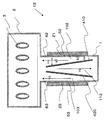
収容部1は、断面が直方体形状の金属製の容器であり、内部に冷媒(例えば水、フロン類など)が貯留されている。収容部1は受熱通路100と、供給通路110と、仕切部400とを備えている。
The accommodating part 1 is a metal container having a rectangular parallelepiped cross section, in which refrigerant (for example, water, chlorofluorocarbons, etc.) is stored. The accommodating portion 1 includes a
凝縮部2は、断面が直方体形状の金属製の容器であり、内部に凝縮パイプ部3を備えている。収容部1の鉛直方向上方に凝縮部2が連なっている。収容部1には鉛直方向側壁部の外面に発熱体Zが取り付けられている。図1において発熱体Zは収容部1の外側に取り付けてあるが、収容部1の内側に取り付けてあっても良い。
The condensing
冷媒循環は、以下のとおりである。受熱面50において発熱体Zから受熱して沸騰した冷媒蒸気が、受熱通路100を上方に向かって流れ、凝縮部2で凝縮され、その凝縮液が供給通路110に流入し、供給通路110が受熱通路100に冷媒を戻す。
The refrigerant circulation is as follows. The refrigerant vapor boiled by receiving heat from the heating element Z on the
本第1実施形態において、受熱通路100は、図1に示すように、およそ収容部1の発熱体Zが取り付けられた鉛直方向側壁面と仕切部400とを含む側壁面(4面)で囲まれた部位である。発熱体Zは、例えば半導体素子等である。
In the first embodiment, as shown in FIG. 1, the
ここで、図1に示す状態を直立状態と称す。つまり、収容部1の発熱体Zが取り付けられた鉛直方向側壁面は、直立状態において、水平面に対して垂直となる。なお、発熱体Zの取付位置は、収容部1の底面よりも上方となっている。以下、図1に基づいて説明する。 Here, the state shown in FIG. 1 is referred to as an upright state. That is, the vertical side wall surface to which the heating element Z of the housing part 1 is attached is perpendicular to the horizontal plane in the upright state. Note that the mounting position of the heating element Z is higher than the bottom surface of the housing portion 1. Hereinafter, a description will be given based on FIG.
収容部1の内部に設けられた仕切部400は、受熱通路100の側面を形成し、収容部1の内部空間を受熱通路100と供給通路110とに仕切っている。仕切部400については後述する。
The
受熱通路100は、発熱体Zの熱を受け、その熱によって受熱通路100内部の冷媒が沸騰する。沸騰した冷媒蒸気は、図1に示す矢印Y1に示すように上昇し、凝縮部2に入る。凝縮部2については後述する。
The
供給通路110は、収容部1の内部で仕切部400によって仕切られた一方側であり、発熱体Zの取り付けられた側壁面とは反対側に位置している。供給通路110は、受熱通路100に連なり且つ並列的に配置されている。供給通路110は、下方が受熱通路100に連通している。これによれば、沸騰により受熱通路100の液面が低下すると、供給通路110内部の冷媒が圧力差により受熱通路100に供給される。従って供給通路110において矢印Y2の方向に冷媒が流れる。
The
凝縮部2は、収容部1の鉛直方向上方にある。凝縮部2の内部は、図1において、右方で収容部1の受熱通路100及び左方で供給通路110に連通している。本第1実施形態において、凝縮部2は収容部1の上方に収容部1の断面直方体形状よりも幅が広い断面直方体形状になっており、収容部1が凝縮部2の幅方向の中央下方に位置しているが、これに限らない。
The condensing
凝縮パイプ部3は、凝縮部2を貫通し、凝縮部2の内部に位置する部位が複数の偏平管の集合体で構成されている。凝縮パイプ部3の内部には、冷媒が流通しており、図示しないヘッダーを介して各偏平管内部に冷媒(冷却水等)が流れている。つまり、凝縮パイプ部3は、凝縮部2に収容され、受熱通路100で沸騰した冷媒蒸気を凝縮する。
The condensing
凝縮パイプ部3は、収容部1の上方に位置している。凝縮パイプ部3で凝縮された冷媒は、重力により下方へ向かうため、凝縮部2の内底面上または直接収容部1に流入する。
内底面上に落ちた冷媒も、その後収容部1に流入する。
The condensing
The refrigerant that has fallen on the inner bottom surface then flows into the accommodating portion 1.
また、仕切部400は板状であり、収容部1の鉛直方向側壁面に平行に延在する上方仕切部と、上方仕切部の下端から収容部1の鉛直方向側面に向かって垂直にある一定距離突き出し、さらに下方に直角に折れて鉛直方向側面に平行に延在する下方仕切部とからなっている。
The
本第1実施形態において仕切部400の上方仕切部の受熱面50と対向する面と受熱面50との間隙の幅a1は仕切部400の下方仕切部の受熱面50と対向する面と受熱面50との間隙の幅b1よりも大きく、仕切部400の受熱面50と対向する面は受熱面50との間隙が受熱面50の上方側が拡幅されている。幅a1は5mm以下が好ましい。特に幅a1は2〜3mm程度が好ましく、幅b1は1〜2mm程度が好ましい。
In the first embodiment, the width a1 of the gap between the
仕切部400の受熱面50と対向する面と受熱面50との間隙が受熱面50の上方側が拡幅されていることにより、受熱面50の下方で発生した気泡が仕切部400の拡幅された上方仕切部面に沿って上昇出来るため、受熱面50の上方で発生した気泡と干渉しにくくなり、出来た気泡が受熱面50の上部に溜まることによる受熱面50の上部の伝熱不良が起こることを抑制出来る。これにより発熱体のバーンアウト(温度急上昇)の抑制が出来る。
The gap between the
またバーンアウトは、離脱、合体する気泡の動きと、気泡に代わって発熱体面または発熱体に接する受熱面に向かう液体流との流体力学的不安定によって生じると考えられている。そして発熱体面または受熱面に加わる加速度が大きいほどバーンアウトが発生しにくくなることが経験的に求められている。従って受熱面50と仕切部400の受熱面50と対向する面との間の間隙を狭くして液体流の圧力を高め、受熱面に向かう液体流の加速度を大きくすると良い。
Burnout is considered to be caused by hydrodynamic instability between the movement of bubbles that separate and merge and the liquid flow toward the heat generating surface or the heat receiving surface in contact with the heat generating body instead of the bubbles. Further, it is empirically required that burnout is less likely to occur as the acceleration applied to the heating element surface or the heat receiving surface increases. Therefore, the gap between the
さらに、気泡の量に合わせ、仕切部の受熱面と対向する面と受熱面との距離を、上方側及び下方側共に気泡を適切に保持することが出来る適切な距離にすることで、沸騰伝熱を向上させることが出来る。 Furthermore, according to the amount of bubbles, the distance between the surface opposite to the heat receiving surface of the partition and the heat receiving surface is set to an appropriate distance that can appropriately hold the bubbles on both the upper side and the lower side. Heat can be improved.
このように、本第1実施形態に記載の沸騰冷却装置10によれば、良好な沸騰伝熱を行うことができる。
Thus, according to the boiling
(第2実施形態)
第2実施形態では沸騰冷却装置11を例に挙げる。以下、沸騰冷却装置11について図2を参照して説明する。図2は、沸騰冷却装置11の模式断面図である。沸騰冷却装置11は、仕切部401の形状が異なるだけで後は第1実施形態で説明した沸騰冷却装置10と同様のものである。そのため第1実施形態で説明したものと同じものは説明を省略し、異なる部分を以下に説明する。
(Second Embodiment)
In the second embodiment, the boiling
図2に示すように沸騰冷却装置11は、収容部1と、凝縮部2とを備えている。収容部1は受熱通路101と、供給通路111と、仕切部401とを備えている。
As shown in FIG. 2, the boiling
仕切部401は板状であり、鉛直方向に対して傾斜している。傾斜角は特に限定されないが、仕切部401の受熱面51と対向する面は、受熱面51との間隙が受熱面51の上方側が拡幅されている方向に傾斜される。本第2実施形態において仕切部401の受熱面51と対向する面の上方側と受熱面51との間隙の幅a2は仕切部401の受熱面51と対向する面の下方側と受熱面51との間隙の幅b2よりも大きく、幅a2は5mm以下が好ましい。特に幅a2は2〜3mm程度が好ましく、幅b2は1〜2mm程度が好ましい。
The
仕切部401の受熱面51と対向する面と受熱面51との間隙が受熱面51の上方側が拡幅されるように傾斜していることにより、受熱面51の下方で発生した気泡が仕切部401の傾斜面に沿って上昇出来るため、受熱面51の上方で発生した気泡と干渉しにくくなり、出来た気泡が受熱面51の上部に溜まることによって受熱面51の上部の伝熱不良が起こることを抑制出来る。これにより発熱体のバーンアウト(温度急上昇)の抑制が出来る。
The gap between the
このように、本第2実施形態に記載の沸騰冷却装置11によれば、良好な沸騰伝熱を行うことができる。
Thus, according to the boiling
またこの第2実施形態では、仕切部401が傾斜しているが、受熱面が形成される収容部1の側壁部が、仕切部の受熱面と対向する面と受熱面との間隙が上方側において拡幅するように傾斜していてもよい。また発熱体Zは収容部1の側壁面の内側に配置される構成としてもよく、その場合発熱体Zの表面に受熱面が形成されることになる。その際、発熱体Zの受熱面の形状が、仕切部の受熱面と対向する面と受熱面との間隙が上方側において拡幅するように傾斜している形状となっていても良い。
Moreover, in this 2nd Embodiment, although the
(第3実施形態)
第3実施形態では沸騰冷却装置12を例に挙げる。以下、沸騰冷却装置12について図3を参照して説明する。図3は、沸騰冷却装置12の模式断面図である。沸騰冷却装置12は、第1発熱体Z1及び第2発熱体Z2が収容部1の相対する側壁面に各々取り付けられている。
(Third embodiment)
In the third embodiment, the boiling
図3に示すように沸騰冷却装置12は、収容部1と、凝縮部2とを備えている。収容部1は第1受熱通路102と、第2受熱通路103と、供給通路112と、第1仕切部410及び第2仕切部420とを備えている。
As shown in FIG. 3, the boiling
収容部1には一方の側壁面及びその対向する面に第1発熱体Z1及び第2発熱体Z2が取り付けられている。図3において第1発熱体Z1及び第2発熱体Z2は収容部1の外側に取り付けてあるが、収容部1の内側に取り付けてあっても良い。 The first heating element Z1 and the second heating element Z2 are attached to the housing portion 1 on one side wall surface and the surface facing the side wall surface. In FIG. 3, the first heating element Z <b> 1 and the second heating element Z <b> 2 are attached to the outside of the housing part 1, but may be attached to the inside of the housing part 1.
冷媒循環は、以下のとおりである。第1受熱通路102において第1発熱体Z1から受熱して沸騰した冷媒蒸気及び第2受熱通路103において第2発熱体Z2から受熱して沸騰した冷媒蒸気が、凝縮部2で凝縮され、その凝縮液が供給通路112に流入し、供給通路112が第1受熱通路102及び第2受熱通路103に冷媒を戻す。
The refrigerant circulation is as follows. The refrigerant vapor boiled by receiving heat from the first heating element Z1 in the first
本第3実施形態において、第1受熱通路102は、図3に示すように、およそ収容部1の第1発熱体Z1が取り付けられた側壁面と第1仕切部410とを含む側面(4面)で囲まれた部位であり、第2受熱通路103は、図3に示すように、およそ収容部1の第2発熱体Z2が取り付けられた側壁面と第2仕切部420とを含む側面(4面)で囲まれた部位である。
In the third embodiment, as shown in FIG. 3, the first
収容部1の内部に設けられた第1仕切部410は、第1受熱通路102の側面を形成し、収容部1の内部空間を第1受熱通路102と供給通路112とに仕切っている。また第2仕切部420は、第2受熱通路103の側面を形成し、収容部1の内部空間を第2受熱通路103と供給通路112とに仕切っている。仕切部410、420については後述する。
The
第1受熱通路102は、第1発熱体Z1の熱を受け、その熱によって第1受熱通路102内部の冷媒が沸騰する。沸騰した冷媒蒸気は、図3に示す矢印Y1に示すように上昇し、凝縮部2に入る。また第2受熱通路103は、第2発熱体Z2の熱を受け、その熱によって第2受熱通路103内部の冷媒が沸騰する。沸騰した冷媒蒸気は、図3に示す矢印Y3に示すように上昇し、凝縮部2に入る。
The first
供給通路112は、収容部1の内部で第1仕切部410及び第2仕切部420によって仕切られており、第1受熱通路102及び第2受熱通路103に連なり且つ各々に並列的に配置されている。供給通路112の内部は、下方が第1受熱通路102及び第2受熱通路103の内部に連通している。これによれば、沸騰により第1受熱通路102及び第2受熱通路103の液面が低下すると、供給通路112内部の冷媒が圧力差により第1受熱通路102及び第2受熱通路103に供給される。従って供給通路112において矢印Y2の方向に冷媒が流れる。
The
凝縮部2及び凝縮パイプ3は第1実施形態と同様であるので説明を省略する。
Since the condensing
第1仕切部410及び第2仕切部420は板状であり、鉛直方向に対して傾斜している。傾斜角は特に限定されないが、第1仕切部410は、第1仕切部410の第1受熱面52に対向する面と第1受熱面52との間隙が第1受熱面52の上方側が拡幅されている方向に傾斜される。また第2仕切部420は、第2仕切部420の第2受熱面53に対向する面と第2受熱面53との間隙が、第2受熱面53の上方側が拡幅されている方向に傾斜される。
The
本第3実施形態において、第1仕切部410の第1受熱面52に対向する面の上方側と第1受熱面52との間隙の幅a3は、第1仕切部410の第1受熱面52に対向する面の下方側と第1受熱面52との間隙の幅b3よりも大きく、幅a3は5mm以下が好ましい。特に幅a3は2〜3mm程度が好ましく、幅b3は1〜2mm程度が好ましい。図で説明されてはいないが、第2仕切部420の第2受熱面53に対向する面と第2受熱面53との位置関係も第1仕切部410の第1受熱面52に対向する面と第1受熱面52との関係と同様である。
In the third embodiment, the width a3 of the gap between the upper side of the surface facing the first
第1仕切部410の第1受熱面52に対向する面と第1受熱面52との間隙が第1受熱面52の上方側が拡幅されるように傾斜していることにより、第1受熱面52の下方で発生した気泡が第1仕切部410の傾斜面に沿って上昇出来るため、第1受熱面52の上方で発生した気泡と干渉しにくくなり、出来た気泡が第1受熱面52の上部に溜まることによって第1受熱面52の上部の伝熱不良が起こることを抑制出来る。これにより発熱体のバーンアウト(温度急上昇)の抑制が出来る。同様のことが第2仕切部420と第2受熱面53とについていえる。
The first
このように、本第3実施形態に記載の沸騰冷却装置12によれば、収容部の両面に発熱体を取り付けても良好な沸騰伝熱を行うことができる。
Thus, according to the boiling
(第4実施形態)
第4実施形態では沸騰冷却装置13を例に挙げる。以下、沸騰冷却装置13について図4を参照して説明する。図4は、沸騰冷却装置13の模式断面図である。沸騰冷却装置13は、第3発熱体Z11及び第4発熱体Z12が収容部1の一方の側壁面に上下に間隔をあけて各々取り付けられており、第5発熱体Z21及び第6発熱体Z22が収容部1の他方の側壁面に上下に間隔をあけて各々取り付けられている。
(Fourth embodiment)
In the fourth embodiment, the boiling
図4に示すように沸騰冷却装置13は、収容部1と、凝縮部2とを備えている。収容部1は第3受熱通路104と、第4受熱通路105と、供給通路113と、第3仕切部411及び第4仕切部421とを備えている。
As shown in FIG. 4, the boiling
収容部1には鉛直方向側面の一方の面に上下に間隔をあけて第3発熱体Z11及び第4発熱体Z12及び他方の面に上下に間隔をあけて第5発熱体Z21及び第6発熱体Z22が取り付けられている。図4において各発熱体は収容部1の外側に取り付けてあるが、収容部1の内側に取り付けてあっても良い。 In the accommodating portion 1, the third heat generating element Z11 and the fourth heat generating element Z12 are spaced apart vertically on one side of the vertical side surface, and the fifth heat generating element Z21 and the sixth heat generating element are spaced apart vertically on the other surface. The body Z22 is attached. In FIG. 4, each heating element is attached to the outside of the housing portion 1, but may be attached to the inside of the housing portion 1.
収容部1の内部に設けられた第3仕切部411は、第3受熱通路104の側面を形成し、収容部1の内部空間を第3受熱通路104と供給通路113とに仕切っている。また第4仕切部421は、第4受熱通路105の側面を形成し、収容部1の内部空間を第4受熱通路105と供給通路113とに仕切っている。
The
第3仕切部411は板状であり、第3受熱面54及び第4受熱面56に面した面が鉛直方向に対して傾斜しており、それ以外は収容部1の側壁面と並行になっている。傾斜角は特に限定されないが、第3仕切部411の第3受熱面54に対向する面は第3受熱面54との間隙が第3受熱面54の上方側が拡幅されている方向に傾斜される。また第3仕切部411の第4受熱面56に対向する面は第4受熱面56との間隙が第4受熱面56の上方側が拡幅されている方向に傾斜される。同様のことが第4仕切部421においても言える。
The
本第4実施形態において第3仕切部411の第3受熱面54に対向する面の上方側と第3受熱面54との間隙の幅a4は第3仕切部411の第4受熱面56に対向する面の下方側と第4受熱面56との間隙の幅b4よりも大きく、幅a4は5mm以下が好ましい。特に幅a4は2〜3mm程度が好ましく、幅b4は1〜2mm程度が好ましい。図示されていないが、第4仕切部421の第5受熱面55に対向する面と第5受熱面55及び第4仕切部421の第6受熱面57に対向する面と第6受熱面57との位置関係も、第3仕切部411の第3受熱面54に対向する面と第3受熱面54及び第3仕切部411の第4受熱面56に対向する面と第4受熱面56との関係と同様である。
In the fourth embodiment, the width a4 of the gap between the upper side of the
第3仕切部411の第3受熱面54に対向する面の上方側と第3受熱面54との間隙が第3受熱面54の上方側が拡幅されるように傾斜していることにより、第4受熱面56の下方で発生した気泡が第3仕切部411の傾斜面に沿って上昇出来るため、第3受熱面54の上方で発生した気泡と干渉しにくくなり、出来た気泡が第3受熱面54の上部に溜まることによる第3発熱体Z11の上部の伝熱不良が起こることを抑制出来る。これにより発熱体のバーンアウト(温度急上昇)の抑制が出来る。同様のことが第4仕切部421と第5発熱体Z21とについていえる。
The gap between the upper side of the surface of the
また本第4実施形態では、発熱体が収容部の側壁部に上下方向に複数取り付けられている。そして発熱体に面した仕切部の面が鉛直方向に傾斜しており、それ以外の仕切部の面が鉛直方向に収容部側面と並行になっているため、各発熱体の取り付けられた間隔が上下方向に離れていても各発熱体に対して適正な斜度を設定することが出来る。このように、本第4実施形態に記載の沸騰冷却装置13によれば、複数の発熱体が上下方向に間隔を開けて取り付けられていても良好な沸騰伝熱を行うことができる。
In the fourth embodiment, a plurality of heating elements are attached in the vertical direction to the side wall of the housing. And the surface of the partition facing the heating element is inclined in the vertical direction, and the other partition surface is parallel to the side surface of the accommodating section in the vertical direction. Even if they are separated in the vertical direction, an appropriate inclination can be set for each heating element. As described above, according to the boiling
また、各実施形態において発熱体Zを受熱通路内に配置する構成としてもよい(浸漬方式)。この場合でも、上記同様の効果を得ることができる。なお、発熱体Zが半導体素子のような電子部品である場合は、絶縁性の冷媒を用いることが好ましい。 Moreover, it is good also as a structure which arrange | positions the heat generating body Z in a heat receiving path in each embodiment (immersion method). Even in this case, the same effect as described above can be obtained. In addition, when the heat generating body Z is an electronic component such as a semiconductor element, it is preferable to use an insulating refrigerant.
1:収容部、2:凝縮部、3:凝縮パイプ部、
100:受熱通路、110:供給通路、400:仕切部、Z:発熱体
1: accommodating part, 2: condensing part, 3: condensing pipe part,
100: heat receiving passage, 110: supply passage, 400: partition, Z: heating element
Claims (5)
前記収容部は、前記液体冷媒が下方から上方に向かって流れると共に、前記受熱面が配置される受熱通路と、前記液体冷媒が供給される供給通路と、前記収容部の内部空間を前記受熱通路と前記供給通路とに仕切る仕切部と、を有する沸騰冷却装置であって、
前記仕切部の前記受熱面と対向する面と前記受熱面との間隙は上方側が拡幅されていることを特徴とする沸騰冷却装置。 It has a heat receiving surface that extends in the vertical direction and receives the heat of the heating element by the liquid refrigerant, and includes an accommodating portion that accommodates the liquid refrigerant inside,
The housing portion includes a heat receiving passage in which the liquid refrigerant flows from below to above and the heat receiving surface is disposed, a supply passage to which the liquid refrigerant is supplied, and an internal space of the housing portion through the heat receiving passage. A boiling cooling device having a partition section that partitions into the supply passage,
The boiling cooling device characterized in that the upper side of the gap between the surface of the partition portion facing the heat receiving surface and the heat receiving surface is widened.
前記収容部は、第1発熱体の熱を液体冷媒が受熱する第1受熱面と前記供給通路とを仕切る第1仕切部と、第2発熱体の熱を液体冷媒が受熱する第2受熱面と前記供給通路とを仕切る第2仕切部とを有し、
前記第1仕切部の前記第1受熱面と対向する面と前記第1受熱面との間隙及び前記第2仕切部の前記第2受熱面と対向する面と前記第2受熱面との間隙は共に上方側が拡幅されている請求項1または2に記載の沸騰冷却装置。 The heating element consists of a first heating element attached to one side wall of the housing part and a second heating element attached to the other opposite side wall,
The accommodating portion includes a first partition for partitioning the supply passage from a first heat receiving surface where the liquid refrigerant receives heat from the first heating element, and a second heat receiving surface where the liquid refrigerant receives heat from the second heating element. And a second partition that partitions the supply passage,
The gap between the first heat receiving surface of the first partition part and the first heat receiving surface and the gap between the second heat receiving surface of the second partition part and the second heat receiving surface are as follows: The boiling cooling device according to claim 1 or 2, wherein both upper sides are widened.
Priority Applications (1)
| Application Number | Priority Date | Filing Date | Title |
|---|---|---|---|
| JP2008164712A JP5092931B2 (en) | 2008-06-24 | 2008-06-24 | Boiling cooler |
Applications Claiming Priority (1)
| Application Number | Priority Date | Filing Date | Title |
|---|---|---|---|
| JP2008164712A JP5092931B2 (en) | 2008-06-24 | 2008-06-24 | Boiling cooler |
Publications (2)
| Publication Number | Publication Date |
|---|---|
| JP2010007893A true JP2010007893A (en) | 2010-01-14 |
| JP5092931B2 JP5092931B2 (en) | 2012-12-05 |
Family
ID=41588619
Family Applications (1)
| Application Number | Title | Priority Date | Filing Date |
|---|---|---|---|
| JP2008164712A Expired - Fee Related JP5092931B2 (en) | 2008-06-24 | 2008-06-24 | Boiling cooler |
Country Status (1)
| Country | Link |
|---|---|
| JP (1) | JP5092931B2 (en) |
Cited By (5)
| Publication number | Priority date | Publication date | Assignee | Title |
|---|---|---|---|---|
| WO2010095373A1 (en) * | 2009-02-23 | 2010-08-26 | 株式会社豊田自動織機 | Ebullient cooling apparatus |
| WO2012161002A1 (en) * | 2011-05-20 | 2012-11-29 | 日本電気株式会社 | Flat plate cooling device, and method for using same |
| JP2013069740A (en) * | 2011-09-21 | 2013-04-18 | Nec Corp | Flat plate type cooling device and usage of the same |
| US11467637B2 (en) | 2018-07-31 | 2022-10-11 | Wuxi Kalannipu Thermal Management Technology Co., Ltd. | Modular computer cooling system |
| US11606880B2 (en) | 2016-03-03 | 2023-03-14 | Wuxi Kalannipu Thermal Management Technology Co., Ltd. | Self-organizing thermodynamic system |
Citations (2)
| Publication number | Priority date | Publication date | Assignee | Title |
|---|---|---|---|---|
| JPS61121373U (en) * | 1985-01-09 | 1986-07-31 | ||
| JPH10173115A (en) * | 1996-12-06 | 1998-06-26 | Toshiba Corp | Ebullient cooling device and its manufacture |
-
2008
- 2008-06-24 JP JP2008164712A patent/JP5092931B2/en not_active Expired - Fee Related
Patent Citations (2)
| Publication number | Priority date | Publication date | Assignee | Title |
|---|---|---|---|---|
| JPS61121373U (en) * | 1985-01-09 | 1986-07-31 | ||
| JPH10173115A (en) * | 1996-12-06 | 1998-06-26 | Toshiba Corp | Ebullient cooling device and its manufacture |
Cited By (7)
| Publication number | Priority date | Publication date | Assignee | Title |
|---|---|---|---|---|
| WO2010095373A1 (en) * | 2009-02-23 | 2010-08-26 | 株式会社豊田自動織機 | Ebullient cooling apparatus |
| WO2012161002A1 (en) * | 2011-05-20 | 2012-11-29 | 日本電気株式会社 | Flat plate cooling device, and method for using same |
| JPWO2012161002A1 (en) * | 2011-05-20 | 2014-07-31 | 日本電気株式会社 | Flat plate cooling device and method of using the same |
| JP5874935B2 (en) * | 2011-05-20 | 2016-03-02 | 日本電気株式会社 | Flat plate cooling device and method of using the same |
| JP2013069740A (en) * | 2011-09-21 | 2013-04-18 | Nec Corp | Flat plate type cooling device and usage of the same |
| US11606880B2 (en) | 2016-03-03 | 2023-03-14 | Wuxi Kalannipu Thermal Management Technology Co., Ltd. | Self-organizing thermodynamic system |
| US11467637B2 (en) | 2018-07-31 | 2022-10-11 | Wuxi Kalannipu Thermal Management Technology Co., Ltd. | Modular computer cooling system |
Also Published As
| Publication number | Publication date |
|---|---|
| JP5092931B2 (en) | 2012-12-05 |
Similar Documents
| Publication | Publication Date | Title |
|---|---|---|
| JP6015675B2 (en) | COOLING DEVICE AND ELECTRONIC DEVICE USING THE SAME | |
| US20140318167A1 (en) | Evaporator, cooling device, and electronic apparatus | |
| JP6137167B2 (en) | Cooling device and cooling system | |
| US20110000649A1 (en) | Heat sink device | |
| US20140165638A1 (en) | Cooling device and electronic device made therewith | |
| US9921003B2 (en) | Wickless heat pipe and thermal ground plane | |
| JP6358872B2 (en) | Boiling cooler for heating element | |
| JP5092931B2 (en) | Boiling cooler | |
| JP6505130B2 (en) | Cooler | |
| JP2010236792A (en) | Ebullient cooling device | |
| JP2013007501A (en) | Cooling device | |
| US11754344B2 (en) | Boiling cooler | |
| JP2009135142A (en) | Ebullient cooling device | |
| JP2013033807A (en) | Cooling device and electronic apparatus using the same | |
| JP2010080507A (en) | Electronic apparatus | |
| US20180249596A1 (en) | Cooler, power conversion apparatus, and cooling system | |
| JP2012237491A (en) | Flat cooling device, method for manufacturing the same and method for using the same | |
| JP2009150575A (en) | Ebullient cooling device | |
| KR101297046B1 (en) | Phase change heat transfer system equipped with vapor fin | |
| JP5163548B2 (en) | Boiling cooler | |
| JP7444703B2 (en) | Heat transfer member and cooling device having heat transfer member | |
| JP2024008436A (en) | Boiling-cooling device | |
| JP2006269694A (en) | Power apparatus | |
| JP2024008426A (en) | Boiling-cooling device | |
| JP2022138222A (en) | Cooling device |
Legal Events
| Date | Code | Title | Description |
|---|---|---|---|
| A621 | Written request for application examination |
Free format text: JAPANESE INTERMEDIATE CODE: A621 Effective date: 20100729 |
|
| A977 | Report on retrieval |
Free format text: JAPANESE INTERMEDIATE CODE: A971007 Effective date: 20111221 |
|
| A131 | Notification of reasons for refusal |
Free format text: JAPANESE INTERMEDIATE CODE: A131 Effective date: 20120110 |
|
| A521 | Written amendment |
Free format text: JAPANESE INTERMEDIATE CODE: A523 Effective date: 20120305 |
|
| TRDD | Decision of grant or rejection written | ||
| A01 | Written decision to grant a patent or to grant a registration (utility model) |
Free format text: JAPANESE INTERMEDIATE CODE: A01 Effective date: 20120821 |
|
| A01 | Written decision to grant a patent or to grant a registration (utility model) |
Free format text: JAPANESE INTERMEDIATE CODE: A01 |
|
| A61 | First payment of annual fees (during grant procedure) |
Free format text: JAPANESE INTERMEDIATE CODE: A61 Effective date: 20120903 |
|
| FPAY | Renewal fee payment (prs date is renewal date of database) |
Free format text: PAYMENT UNTIL: 20150928 Year of fee payment: 3 |
|
| LAPS | Cancellation because of no payment of annual fees |