JP2010003686A - Secondary battery and its manufacturing method - Google Patents
Secondary battery and its manufacturing method Download PDFInfo
- Publication number
- JP2010003686A JP2010003686A JP2009129151A JP2009129151A JP2010003686A JP 2010003686 A JP2010003686 A JP 2010003686A JP 2009129151 A JP2009129151 A JP 2009129151A JP 2009129151 A JP2009129151 A JP 2009129151A JP 2010003686 A JP2010003686 A JP 2010003686A
- Authority
- JP
- Japan
- Prior art keywords
- case
- secondary battery
- conductive member
- electrode assembly
- electrode plate
- Prior art date
- Legal status (The legal status is an assumption and is not a legal conclusion. Google has not performed a legal analysis and makes no representation as to the accuracy of the status listed.)
- Granted
Links
Images


Classifications
-
- H—ELECTRICITY
- H01—ELECTRIC ELEMENTS
- H01M—PROCESSES OR MEANS, e.g. BATTERIES, FOR THE DIRECT CONVERSION OF CHEMICAL ENERGY INTO ELECTRICAL ENERGY
- H01M50/00—Constructional details or processes of manufacture of the non-active parts of electrochemical cells other than fuel cells, e.g. hybrid cells
- H01M50/50—Current conducting connections for cells or batteries
- H01M50/528—Fixed electrical connections, i.e. not intended for disconnection
-
- B—PERFORMING OPERATIONS; TRANSPORTING
- B23—MACHINE TOOLS; METAL-WORKING NOT OTHERWISE PROVIDED FOR
- B23K—SOLDERING OR UNSOLDERING; WELDING; CLADDING OR PLATING BY SOLDERING OR WELDING; CUTTING BY APPLYING HEAT LOCALLY, e.g. FLAME CUTTING; WORKING BY LASER BEAM
- B23K26/00—Working by laser beam, e.g. welding, cutting or boring
- B23K26/20—Bonding
- B23K26/21—Bonding by welding
-
- H—ELECTRICITY
- H01—ELECTRIC ELEMENTS
- H01M—PROCESSES OR MEANS, e.g. BATTERIES, FOR THE DIRECT CONVERSION OF CHEMICAL ENERGY INTO ELECTRICAL ENERGY
- H01M50/00—Constructional details or processes of manufacture of the non-active parts of electrochemical cells other than fuel cells, e.g. hybrid cells
- H01M50/50—Current conducting connections for cells or batteries
- H01M50/528—Fixed electrical connections, i.e. not intended for disconnection
- H01M50/529—Intercell connections through partitions, e.g. in a battery casing
-
- H—ELECTRICITY
- H01—ELECTRIC ELEMENTS
- H01M—PROCESSES OR MEANS, e.g. BATTERIES, FOR THE DIRECT CONVERSION OF CHEMICAL ENERGY INTO ELECTRICAL ENERGY
- H01M50/00—Constructional details or processes of manufacture of the non-active parts of electrochemical cells other than fuel cells, e.g. hybrid cells
- H01M50/50—Current conducting connections for cells or batteries
- H01M50/531—Electrode connections inside a battery casing
- H01M50/534—Electrode connections inside a battery casing characterised by the material of the leads or tabs
-
- H—ELECTRICITY
- H01—ELECTRIC ELEMENTS
- H01M—PROCESSES OR MEANS, e.g. BATTERIES, FOR THE DIRECT CONVERSION OF CHEMICAL ENERGY INTO ELECTRICAL ENERGY
- H01M50/00—Constructional details or processes of manufacture of the non-active parts of electrochemical cells other than fuel cells, e.g. hybrid cells
- H01M50/50—Current conducting connections for cells or batteries
- H01M50/531—Electrode connections inside a battery casing
- H01M50/536—Electrode connections inside a battery casing characterised by the method of fixing the leads to the electrodes, e.g. by welding
-
- B—PERFORMING OPERATIONS; TRANSPORTING
- B23—MACHINE TOOLS; METAL-WORKING NOT OTHERWISE PROVIDED FOR
- B23K—SOLDERING OR UNSOLDERING; WELDING; CLADDING OR PLATING BY SOLDERING OR WELDING; CUTTING BY APPLYING HEAT LOCALLY, e.g. FLAME CUTTING; WORKING BY LASER BEAM
- B23K2101/00—Articles made by soldering, welding or cutting
- B23K2101/36—Electric or electronic devices
- B23K2101/38—Conductors
-
- Y—GENERAL TAGGING OF NEW TECHNOLOGICAL DEVELOPMENTS; GENERAL TAGGING OF CROSS-SECTIONAL TECHNOLOGIES SPANNING OVER SEVERAL SECTIONS OF THE IPC; TECHNICAL SUBJECTS COVERED BY FORMER USPC CROSS-REFERENCE ART COLLECTIONS [XRACs] AND DIGESTS
- Y02—TECHNOLOGIES OR APPLICATIONS FOR MITIGATION OR ADAPTATION AGAINST CLIMATE CHANGE
- Y02E—REDUCTION OF GREENHOUSE GAS [GHG] EMISSIONS, RELATED TO ENERGY GENERATION, TRANSMISSION OR DISTRIBUTION
- Y02E60/00—Enabling technologies; Technologies with a potential or indirect contribution to GHG emissions mitigation
- Y02E60/10—Energy storage using batteries
-
- Y—GENERAL TAGGING OF NEW TECHNOLOGICAL DEVELOPMENTS; GENERAL TAGGING OF CROSS-SECTIONAL TECHNOLOGIES SPANNING OVER SEVERAL SECTIONS OF THE IPC; TECHNICAL SUBJECTS COVERED BY FORMER USPC CROSS-REFERENCE ART COLLECTIONS [XRACs] AND DIGESTS
- Y02—TECHNOLOGIES OR APPLICATIONS FOR MITIGATION OR ADAPTATION AGAINST CLIMATE CHANGE
- Y02P—CLIMATE CHANGE MITIGATION TECHNOLOGIES IN THE PRODUCTION OR PROCESSING OF GOODS
- Y02P70/00—Climate change mitigation technologies in the production process for final industrial or consumer products
- Y02P70/50—Manufacturing or production processes characterised by the final manufactured product
-
- Y—GENERAL TAGGING OF NEW TECHNOLOGICAL DEVELOPMENTS; GENERAL TAGGING OF CROSS-SECTIONAL TECHNOLOGIES SPANNING OVER SEVERAL SECTIONS OF THE IPC; TECHNICAL SUBJECTS COVERED BY FORMER USPC CROSS-REFERENCE ART COLLECTIONS [XRACs] AND DIGESTS
- Y10—TECHNICAL SUBJECTS COVERED BY FORMER USPC
- Y10T—TECHNICAL SUBJECTS COVERED BY FORMER US CLASSIFICATION
- Y10T29/00—Metal working
- Y10T29/49—Method of mechanical manufacture
- Y10T29/49002—Electrical device making
- Y10T29/49108—Electric battery cell making
Abstract
Description
本発明は、二次電池及びその製造方法に関する。 The present invention relates to a secondary battery and a method for manufacturing the same.
典型的なリチウムイオン二次電池で、電極組立体と電解質はケースに収容されて密封される。このようなリチウムイオン二次電池は、ケースの材質によって缶型リチウムイオン二次電池とパウチ型リチウムイオン二次電池に分けられる。 In a typical lithium ion secondary battery, the electrode assembly and the electrolyte are housed in a case and sealed. Such lithium ion secondary batteries are classified into can type lithium ion secondary batteries and pouch type lithium ion secondary batteries according to the material of the case.
例えば、缶型リチウムイオン二次電池は、電極組立体と電極組立体の正極と陰極に電気的に連結される金属材質のケースを含んで形成される。前記電極組立体は、リードタップによってケースと電気的に連結される。ケースとリードタップの連結はある適正な方法によって行われて、主に抵抗溶接によって行われる。 For example, a can-type lithium ion secondary battery is formed including an electrode assembly and a metal case electrically connected to a positive electrode and a cathode of the electrode assembly. The electrode assembly is electrically connected to the case by a lead tap. The case and the lead tap are connected by an appropriate method, and mainly by resistance welding.
しかし、前記抵抗溶接は溶接過程で電極組立体とケースのショートを誘発させる溶接スパッタ(spatter)が発生するという問題があった。 However, the resistance welding has a problem in that welding spatter that induces short-circuit between the electrode assembly and the case occurs during the welding process.
前記電極組立体とケースとの間の電気伝導性を増加させようとする場合に、たびたび二つ以上の部分的に重なるリードタップが使われる。このような場合に、抵抗溶接がそれぞれのリードタップをケースに連結させるためにたびたび遂行されるが、これは製造工程時間を増加させて製造工程を複雑にさせる。 When trying to increase the electrical conductivity between the electrode assembly and the case, two or more partially overlapping lead taps are often used. In such cases, resistance welding is often performed to connect each lead tap to the case, which increases the manufacturing process time and complicates the manufacturing process.
さらに、前記ケースとリードタップとの間の抵抗溶接は、抵抗溶接過程で欠陷がある溶接結合を誘発するようになる。たびたび、前記リードを形成する材料は低い抵抗を有し、これは発生する熱を減少させて不十分な溶接を誘発するようになる。 Furthermore, the resistance welding between the case and the lead tap will induce a weld joint that is defective in the resistance welding process. Often, the material forming the leads has a low resistance, which reduces the heat generated and induces poor welding.
そこで、本発明は、上記課題に鑑みてなされたものであり、本発明の目的とするところは、ケースと少なくとも一つのリードタップが連結される過程でケースの内部に残存物またはスパッタが発生されないようにする二次電池及びその製造方法を提供することにある。 Therefore, the present invention has been made in view of the above problems, and an object of the present invention is to prevent residue or spatter from being generated inside the case in the process of connecting the case and at least one lead tap. An object of the present invention is to provide a secondary battery and a manufacturing method thereof.
また、本発明はケースと複数個のリードタップを連結する過程で工程段階の数が増加されないようにする二次電池及びその製造方法を提供することに他の目的がある。 Another object of the present invention is to provide a secondary battery and a method of manufacturing the same that prevents the number of process steps from being increased in the process of connecting a case and a plurality of lead taps.
また、本発明はケースと少なくとも一つのリードタップとの間の接触抵抗を考慮しなくても良い溶接性を有する溶接部が形成されることができる二次電池及びその製造方法を提供することにまた他の目的がある。 Another object of the present invention is to provide a secondary battery in which a welded portion having weldability that does not require consideration of contact resistance between a case and at least one lead tap can be formed, and a method for manufacturing the same. There are other purposes as well.
本発明にかかる二次電池は、導電性材料で形成されて、外部面を具備して内部空間を限定して、第1表面を具備する缶を含むケースを含む。また、前記二次電池は第1電極板と第2電極板及び前記第1電極板と第2電極板との間に配置されるセパレーターを具備して、前記ケースの内部空間に位置する電極組立体を含む。また、前記二次電池は第2電極板に結合される少なくとも一つの導電部材を含んで、前記少なくとも一つの導電部材は第1位置で前記第1表面に溶接されて、溶接部は前記ケースの外部から形成されることができる。また、前記溶接部は断面積が前記少なくとも一つの導電部材でより前記ケースの外部表面でさらに大きくて、ケースの内部に延長されて形成されることができる。 The secondary battery according to the present invention includes a case formed of a conductive material, including a can having a first surface, having an outer surface and limiting an inner space. The secondary battery includes a first electrode plate, a second electrode plate, and a separator disposed between the first electrode plate and the second electrode plate, and an electrode set positioned in the internal space of the case. Includes solids. The secondary battery includes at least one conductive member coupled to a second electrode plate, the at least one conductive member is welded to the first surface at a first position, and a welded portion of the case Can be formed from the outside. The weld may have a cross-sectional area that is larger on the outer surface of the case than that of the at least one conductive member, and is extended to the inside of the case.
本発明にかかる二次電池の製造方法は、正極板と負極板及び前記正極板と負極板との間に位置するセパレーターを具備する電極組立体を提供する段階と少なくとも一つの導電部材を前記電極組立体に連結する段階を含むことができる。また、前記二次電池の製造方法は、前記正極板と負極板及びセパレーターを具備する前記電極組立体をケースの内部に位置させる段階と前記少なくとも一つの導電部材を前記ケースの第1表面に接触させる段階を含むことができる。また、前記二次電池の製造方法は、前記ケースを前記少なくとも一つの導電部材の第1段に溶接する段階を含んで、前記溶接部は前記ケースの外部面から形成されて、前記電極組立体にスパッタが流入されることを防止するようになされることができる。 A method of manufacturing a secondary battery according to the present invention includes providing an electrode assembly including a positive electrode plate, a negative electrode plate, and a separator positioned between the positive electrode plate and the negative electrode plate, and at least one conductive member. A step of connecting to the assembly may be included. The method for manufacturing a secondary battery may include a step of positioning the electrode assembly including the positive electrode plate, the negative electrode plate, and a separator in a case, and contacting the at least one conductive member with the first surface of the case. A step of allowing to include. The method for manufacturing a secondary battery includes a step of welding the case to a first stage of the at least one conductive member, wherein the weld is formed from an outer surface of the case, and the electrode assembly It is possible to prevent spatter from flowing into the substrate.
以上説明したように本発明によれば、ケースとリードタップを連結する過程でケースの内部にスパッタが発生されないので、二次電池の安全性を向上することができる。 As described above, according to the present invention, since spatter is not generated inside the case in the process of connecting the case and the lead tap, the safety of the secondary battery can be improved.
また、本発明によれば、ケースと複数個のリードタップを連結する過程で工程段階の数が増加されなくて、製造時間を短縮させることができる。 In addition, according to the present invention, the number of process steps is not increased in the process of connecting the case and the plurality of lead taps, and the manufacturing time can be shortened.
さらに、また、本発明によれば、ケースとリードタップとの間の接触抵抗を考慮しなくても良い溶接性を有する溶接部を形成して溶接不良を減少させることができる。 Furthermore, according to the present invention, it is possible to form a weld portion having weldability that does not require consideration of the contact resistance between the case and the lead tap, thereby reducing welding defects.
以下に添付図面を参照しながら、本発明の好適な実施の形態について詳細に説明する。なお、本明細書及び図面において、実質的に同一の機能構成を有する構成要素については、同一の符号を付することにより重複説明を省略する。また、それぞれの実施例では同一又は類似な効果及び作用に対して重複して説明しないことにする。 Exemplary embodiments of the present invention will be described below in detail with reference to the accompanying drawings. In addition, in this specification and drawing, about the component which has the substantially same function structure, duplication description is abbreviate | omitted by attaching | subjecting the same code | symbol. In each embodiment, the same or similar effects and actions will not be described repeatedly.
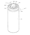
図1Aは、本発明の第1の実施形態にかかる二次電池の分解斜視図である。図1Bは図1Aに示された二次電池が結合された状態の斜視図である。図1Cは図1Bに示された二次電池のI−I線による断面図である。図1Dは、図1Cに示された1d領域に対する部分拡大断面図である。図1Eは、図1Dに対応する比較例による二次電池の部分断面図である。 FIG. 1A is an exploded perspective view of the secondary battery according to the first embodiment of the present invention. FIG. 1B is a perspective view illustrating a state in which the secondary battery illustrated in FIG. 1A is coupled. 1C is a cross-sectional view taken along line II of the secondary battery shown in FIG. 1B. FIG. 1D is a partially enlarged cross-sectional view of the 1d region shown in FIG. 1C. FIG. 1E is a partial cross-sectional view of a secondary battery according to a comparative example corresponding to FIG. 1D.
図1A〜図1Dに示されたところのように、本発明の一実施例による二次電池100は、電極組立体110、ケース120、リードタップ130及び溶接部140を含んで形成される。また、前記二次電池100は絶縁部材(isolation member)として上部絶縁板150と下部絶縁板160をさらに含んで形成される。
As shown in FIGS. 1A to 1D, the
前記電極組立体110は、正極板111と負極板112及びセパレーター113を含んで形成される。前記セパレーター113は正極板111と負極板112との間に正極板111と負極板112を分離するために配置される。また、前記正極板111、セパレーター113及び負極板112はゼリー−ロール形態で巻取されて電極組立体110を形成する。前記電極組立体110の巻取中心部には通路110aが形成される。以下で前記正極板111は、第1電極板に、前記負極板112は、第2電極板に形成される。
The
前記正極板111は、正極集電体と正極活物質層から構成されている。前記正極活物質層はリチウムを含む層状化合物と、正極活物質粒子らの間の結合力を向上させるバインダー、正極活物質層の伝導性を向上させる導電材を含むことができる。前記正極集電体は、一般的にアルミニウムが使われて正極活物質層を支持する役割をするようになる。
The
前記負極板112は、陰極集電体と陰極活物質層とから構成される。前記陰極活物質層は、ハードカーボンまたは黒煙のようなカーボンと、陰極活物質粒子との間の結合力を向上させるバインダーを含むことができる。前記陰極集電体は一般的に銅が使われて、陰極活物質層を支持する役割をするようになる。
The
前記セパレーター113は、正極板111と負極板112との間に介されて正極板111と負極板112を絶縁させて、イオンらを通過させる。前記セパレーター113は一般的にポリエチレン(PE)またはポリプロピレン(PP)で形成されて、但し、ここでその材質を限定するものではない。
The
前記電極組立体110は、正極板111に付着した正極タップ114をさらに含んで形成されることができる。また、前記正極タップ114はサブ組立体122eと電気的に連結される。前記正極タップ114はニッケルまたはニッケルを含む合金のような電気伝導性金属で形成されることができる。
The
前記ケース120は、缶121と、キャップ組立体122を含んで形成される。本実施形態で、前記ケース120は電極組立体110を収容して密閉させる役割をする。また、前記ケース120は電解液(図示せず)を収容することができる。一方、前記ケース120は図面上で円筒状に示したが、前記ケース120は、本発明の技術的思想から脱することがなければ断面が多角形状または多数の他の形状で形成されることがあるというものとして理解されてもよい。
The
前記缶121は、外部面を具備して内部空間を限定して、底表面を具備するようになる。また、前記缶121は少なくとも一つの側壁と少なくとも一つの垂直表面を具備することができるし、少なくとも一つの垂直表面は少なくとも一つの側壁と垂直方向に形成されることができる。また、前記缶121の少なくとも一つの垂直表面は缶の底表面に形成されることができる。また、前記缶121は一端部に開口部121aが形成されて、開口部121aを通じて内部空間に電極組立体110を収容する。
The can 121 has an outer surface, limits an inner space, and has a bottom surface. In addition, the
前記缶121は、缶121の外周部に沿ってビーディング部121bが形成される。前記ビーディング部121bは絶縁ガスケット122dの下端と電極組立体110の上面の間で凹な構造を有するように内部方向に凹に入って行くように形成される。また、前記開口部121aは折曲部121cが形成されるように折曲される。前記折曲部121cは絶縁ガスケット122dの上部周囲表面と密着される。
The can 121 has a
前記缶121は、アルミニウムまたはステンレススチールのような伝導性金属材質で形成されて、リードタップ130のような導電部材130と電気的に連結される。また、前記下部絶縁板160は缶121の内部底表面に設置されて、電極組立体110の下部表面と缶121の内部底表面を電気的に絶縁させるようになる。
The can 121 is formed of a conductive metal material such as aluminum or stainless steel, and is electrically connected to a
前記キャップ組立体122はキャップアップ122a、安全素子122b、安全ベント122c、絶縁ガスケット122dを含む。また、前記キャップ組立体122はサブ組立体122eをさらに含んで形成されることができる。前記キャップ組立体122は絶縁ガスケット122dによって缶121から電気的に絶縁される。
The
前記キャップアップ122aは、キャップアップ122aの中央で突き出される円形突出部122a1を含む。また、前記キャップアップ122aは円形突出部122a1の円形フレーム部にガスを排出するために形成される多数のガス排出ホール122a2を含む。前記キャップアップ122aはステンレススチールと同じ金属材質で形成されて、安全素子122bに電気的に連結されることができる。
The cap-up 122a includes a circular protrusion 122a1 protruding at the center of the cap-up 122a. The cap-up 122a includes a plurality of gas discharge holes 122a2 formed to discharge gas to the circular frame portion of the circular protrusion 122a1. The cap-up 122a may be formed of the same metal material as stainless steel and electrically connected to the
前記安全素子122bは、キャップアップ122aと安全ベント122cとの間に配置される。前記安全素子122bは円形のリング形状で形成されてキャップアップ122aと安全ベント122cを電気的に連結させる。本実施形態にかかる二次電池の場合、前記安全素子122bはPTC素子で形成されることができる。前記安全素子122bは二次電池100の温度が臨界値以上に上昇される場合にキャップアップ122aと安全ベント122cとの間の電流を遮断して、二次電池100の過熱及び爆発を防止する。
The
前記安全ベント122cは、安全素子122bの下部に配置される。また、前記安全ベント122cは破断溝122c1が形成される。前記破断溝122c1は、二次電池100の内部圧力が特定臨界値で上昇する場合に破断される。このような破断で二次電池の内部ガスはガス排出ホール122a2を通じて排出されて、二次電池100の内部圧力の過度な増加による損傷または爆発から二次電池100を保護するようになる。
The
前記絶縁ガスケット122dは、外郭円周部の一部が折曲されてキャップアップ122aと安全素子122b及び安全ベント122cの外郭円周部を囲む。ここで、前記絶縁ガスケット122dは缶121に形成されるビーディング部121bと折曲部121cによって缶121と一体型で結合する。本実施形態にかかる二次電池の場合、前記絶縁ガスケット122dは、ポリエチレンテレフタレート(PET;Polyethylene Terephthalate)やポリエチレン(PE;Polyethylene)のような樹脂材質で形成されて、缶121とキャップ組立体122との構成要素を絶縁させるようになる。
The insulating
前記サブ組立体122eは安全ベント122cの下部面に配置される。
The
本実施形態にかかる二次電池の場合、前記サブ組立体122eは絶縁プレート121e1と絶縁プレート121e1に密着されたメインプレート121e2及びメインプレート121e2に接続されたサブプレート121e3を含むことができる。
In the case of the secondary battery according to the present embodiment, the
前記絶縁プレート122e1は、安全ベント122cとメインプレート122e2との間に配置されて、安全ベント122cとメインプレート122e2を絶縁させる。前記安全ベント122cは何の障害なしにサブプレート122e3と電気的に連結されることが必要である。このために、前記絶縁プレート122e1は、安全ベント122cとメインプレート122e2を絶縁させるためにメインプレート122e2の上面一部に形成される。
The insulating plate 122e1 is disposed between the
前記メインプレート121e2は、下部面にメインプレート121e2の直径より小さな直径を有する突出部が形成される。また、中央ホール122e4が突出部の間に形成される。前記メインプレート121e2に形成された中央ホール122e4の周辺には缶121の内部ガス排出を円滑にさせるためのガス通過ホール122e5らが形成される。
The main plate 121e2 is provided with a protrusion having a diameter smaller than that of the main plate 121e2 on the lower surface. A central hole 122e4 is formed between the protrusions. Around the central hole 122e4 formed in the main plate 121e2, gas passage holes 122e5 and the like for smoothly discharging the internal gas of the
前記サブプレート122e3は、メインプレート121e2の中央ホール122e4を覆うようにメインプレート121e2の下部に結合されて、メインプレート121e2と電気的に連結される。また、前記サブプレート122e3は、安全ベント122cと電気的に連結されて、正極タップ114と電気的に連結される。
The sub plate 122e3 is coupled to the lower part of the main plate 121e2 so as to cover the central hole 122e4 of the main plate 121e2, and is electrically connected to the main plate 121e2. The sub plate 122e3 is electrically connected to the
前記リードタップ130は、導電部材としてケース120に収容されて、電極組立体110の負極板112をケース120に電気的に連結させる。また、前記リードタップ130は電極組立体110の下部表面と缶121の内部底表面との間に挿入されるように折曲される。よって、前記リードタップ130は電極組立体110から缶121の側壁に平行に延長される第1部と、第1部から缶121の底表面に平行に延長される第2部を具備することができる。よって、前記リードタップ130の第1部は絶縁部材と側壁との間に位置するようになって、第2部は絶縁部材と缶121の底表面との間に位置することができる。ここで、前記絶縁部材は以下で説明する下部絶縁板であることができる。
The
前記リードタップ130は、伝導性金属材質で形成される。特に、前記リードタップ130はニッケル、銅、アルミニウム、ステンレススチール及びこれらの合金のうちで選択されるいずれか一つの材質でなされることができる。
The
前記缶121は、溶接部140によってリードタップ130に連結される。前記溶接部140は、缶121の第1表面から缶121とリードタップ130の第1位置まで形成される。ここで、前記第1表面は外部底表面であることができるし、前記第1位置は缶121とリードタップ130の接触位置であることができる。したがって、前記溶接部140は缶121の第1表面である外部底表面でレーザー溶接によって形成される。図示したように、前記溶接部140はリードタップ130が位置する缶120の外部表面断面積が内部表面の断面積より大きくなるように形成されることができる。
The can 121 is connected to the
また、本実施形態にかかる二次電池で前記溶接部140が缶121の第1表面である底表面に形成されたが、前記溶接部140はキャップ組立体122のキャップアップ122aのような外部表面にも形成されることができる。すなわち、前記溶接部140はリードタップ130の結合位置によってケース120のどこに形成されてもよい。
In the secondary battery according to the present embodiment, the welded
前記溶接部140は、缶121の開口部121aと対向する面である底表面に形成される。前記缶121はリードタップ130によって負極板112と電気的に連結される。このような場合に、前記二次電池は他の二次電池と直列で連結されて高電圧のバッテリーパックを形成するようになる。例えば、前記缶121の底表面は他の二次電池らの正極と電気的に連結される。よって、前記溶接部140が底表面に形成された二次電池は他の二次電池と直列で連結される時、二次電池間の電気的な連結経路が最小化される。その結果、前記二次電池らの内部抵抗が減少されて、二次電池の発熱を防止するようになる。
The welded
前記上部絶縁板150は、電極組立体110の上部表面に位置する。前記上部絶縁板150は、電極組立体110の上部表面に位置して、サブ組立体122eと電極組立体110を絶縁させる役割をする。また、前記上部絶縁板150には中央に正極タップ通過ホール151が形成されて正極タップ114を通過させる。
The upper insulating
前記下部絶縁板160は、電極組立体110の下部表面に配置される。前記下部絶縁板160は円形の板形状で形成されて、電極組立体110の底表面とリードタップ130との間を絶縁させる役割をする。
The lower insulating
前記したところのような二次電池は、缶121の外部底表面でレーザー溶接が施行されて、リードタップ130が缶121に連結されるので安全性が向上する。図1Eを参照すると、図1Dの比較例による関連技術にかかる二次電池の部分断面図が示されている。図1Eを参照すると、関連技術にかかる二次電池で、抵抗溶接部140fは缶121とリードタップ130eが接触される領域に形成される。前記抵抗溶接部140fは次のような過程によって形成される。先ず、前記リードタップ130eと缶121を正極棒11aと陰極棒11bで利用して接触させる。前記正極棒11aと陰極棒11bを通じて電流が流れる時、リードタップ130eと缶121の接触領域のうちで接触抵抗が一番高い接触領域で熱が発生して、接触領域を溶融させるようになる。その結果、前記リードタップ130eは缶121の底面と結合するようになる。リードタップ130eは缶121との間で接触抵抗を高めるために複数個の突起130e1が形成される。前記突起130e1らは抵抗溶接でたびたび必要な追加的なスポット溶接を含んで、製造費用を増加させることができる。
Since the secondary battery as described above is laser-welded on the outer bottom surface of the
前記抵抗溶接は、溶接方式の特性上抵抗溶接部140fでスパッタ(spatter)の発生を伴うようになる。前記スパッタは、リードタップ130eと缶121の接触領域(または、第1位置)が溶融される時に発生する熱い粒子で形成された火花である。前記スパッタは、電極組立体110の通路110aや電極組立体110の下部面に流入される。特に、前記スパッタが電極組立体110の通路110aに飛散されて流入される場合、電極組立体110のショートを誘発させて電極組立体110の安全性を低下させるようになる。また、前記スパッタ粒子はパーティクル(particle)形態で堅く固まって缶121の内部に残存するようになるので、電極組立体110の安全性に悪い影響を与えるようになる。
The resistance welding is accompanied by generation of spatter at the
しかし、本発明の第1の実施形態にかかる二次電池は、レーザー溶接方式を利用するようになるので、抵抗溶接部の溶接方式とは違いスパッタの発生を抑えて安全性が向上する。さらに、本発明の第1の実施形態にかかる二次電池では前記溶接が缶121の外部底表面で施行されるので、溶接不良をより容易に肉眼で識別することができる。
However, since the secondary battery according to the first embodiment of the present invention uses a laser welding method, unlike the welding method of the resistance welding portion, the occurrence of spatter is suppressed and the safety is improved. Furthermore, in the secondary battery according to the first embodiment of the present invention, since the welding is performed on the outer bottom surface of the
図2は、本発明の第2の実施形態にかかる二次電池の部分断面図である。 FIG. 2 is a partial cross-sectional view of a secondary battery according to the second embodiment of the present invention.
図2を参照すると、本発明の第2の実施形態にかかる二次電池は、電極組立体110、ケース(一部図示)121、第1リードタップ231と第2リードタップ232及び、溶接部240を含んで形成される。前記電極組立体110及びケース(一部図示)121は以前の実施例で説明したところと同一であるので、ここで反復される説明は省略する。本実施形態にかかる二次電池では、リードタップら231、232と溶接部240について以下でより具体的に説明する。
Referring to FIG. 2, the secondary battery according to the second embodiment of the present invention includes an
前記第1リードタップ231及び第2リードタップ232は電極組立体110の負極板と電気的に連結される。この時、前記第1リードタップ231と第2リードタップ232は電極組立体110の両側に位置する第1面と第2面にそれぞれ結合されることができる。ここで、前記第1面と第2面は電極組立体110の外側でお互いに対向する任意の二つの面を意味することができる。一方、前記第1リードタップ231と第2リードタップ232は溶接部が形成される位置で部分的に互いに重なるように形成される。この場合、溶接部240は缶121の外部底表面(または、第1表面)で複数個のリードタップ231、232が互いに重なった位置(または、第1位置)まで延長される。前記溶接部240は、レーザー溶接によって形成される。よって、レーザーのエネルギーと照射時間を調節すると、缶121の外部底表面から複数個のリードタップが重なった部位まで溶接の深さを制御することができる。
The
レーザー溶接の結果によって、前記第1リードタップ231と第2リードタップ232が電極組立体110の負極板と電気的に連結されるので、電極組立体110と缶121が電気的に連結される。
As a result of the laser welding, the
前記第1リードタップ231は、ニッケル、銅、アルミニウム及びステンレススチールのうちで選択されたいずれか一つの材質でなされるか、またはこれらの合金でなされる。また、前記第2リードタップ232はニッケル、銅、アルミニウム及び、ステンレススチールのうちで選択されたいずれか一つの材質でなされるか、またはこれらの合金でなされる。前記溶接部240は、第1リードタップ231と第2リードタップ232の材質にかかわらずレーザー溶接によって形成されることができる。
The
前記リードタップ231、232は材質にかかわらず溶接前にお互いに部分的に重なることができる。例えば、前記第1リードタップ231と第2リードタップ232がそれぞれニッケルと銅で形成される時、これらは何の欠陷がなしにレーザー溶接によって溶接されることができる。結論として、前記溶接部240はリードタップ231、232の材質にかかわらず形成されることができる。
The lead taps 231 and 232 can partially overlap each other before welding regardless of the material. For example, when the first and second
一方、図1Eを参照すると、前記抵抗溶接部140fは工程の特定上、一つのリードタップ130eと缶121の内側面を比較的簡単な方法によって形成することができる。抵抗溶接によって重なったリードタップ231、232を溶接しようとする場合には、その工程が非常に複雑になる。しかし、本実施例で前記溶接部240は、リードタップ231、232と缶121を互いに接触させた後、レーザー溶接によってリードタップ231、232らと缶121を非常に簡単な方法で結合させて形成することができる。
On the other hand, referring to FIG. 1E, the
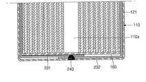
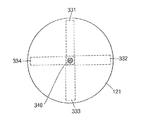
図3Aは、本発明のまた他の実施例による二次電池の部分断面図である。図3Bは図3Aに示された二次電池の底面図である。 FIG. 3A is a partial cross-sectional view of a rechargeable battery according to another embodiment of the present invention. 3B is a bottom view of the secondary battery shown in FIG. 3A.
図3A及び図3Bに示すように、本発明のまた他の実施例による二次電池は、電極組立体110、ケース(一部図示)121、第1リードタップ331、第2リードタップ332、第3リードタップ333、第4リードタップ334及び、溶接部340を含んで形成される。前記電極組立体110及びケース(一部図示)121は前の実施例で説明したところのように同一であるので、反復的な説明は省略する。本実施形態では、リードタップら331、332、333、334と溶接部340に対してより具体的に説明する。
3A and 3B, the secondary battery according to another embodiment of the present invention includes an
図3Bに示すように、前記リードタップ331、332、333、334らは缶121の中央でお互いに部分的に重なって十字形状で形成される。前記リードタップ331、332、333、334らは電極組立体110の負極板112に一定な間隔で付着する。この時、前記電極組立体110はリードタップをそれぞれ付着する部分である第1側、第2側、第3側及び第4側を具備することができる。前記第1側、第2側、第3側及び第4側は、電極組立体110の外側で、一定角度でお互いに離隔される領域で限定されることができる。
As shown in FIG. 3B, the lead taps 331, 332, 333, 334 and the like are formed in a cross shape by partially overlapping each other at the center of the
前記溶接部340は、缶121の外部底表面にレーザーが照射されて形成される。その結果、前記リードタップ331、332、333、334は缶121の外部底表面から第1リードタップ331まで溶融されて缶121に固着する。
The welded
前記二次電池で前記缶121は、リードタップ331、332、333、334らによって電極組立体110と電気的になる。このような構造によって、前記電極組立体110は、缶121の下部面まで高出力のエネルギーを瞬間的に、またはほとんど瞬間的に放出することができる。瞬間的なエネルギー放出が可能なことは缶121の外部面でレーザー溶接によって複数個のリードタップ331、332、333、334らが缶121と電気的に連結されるからである。
In the secondary battery, the
本実施例で、前記レーザー溶接は複数個のリードタップ331、332、333、334を缶121と連結させるために、缶121の外部面で実施される。よって、前記レーザー溶接は、抵抗溶接に比べて非常に簡単な方法で溶接部を形成するために使われることができる。
In this embodiment, the laser welding is performed on the outer surface of the
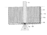
図4Aは、本発明の一実施例による二次電池製造方法の流れ図である。図4B〜図4Dは、図4Aの二次電池製造方法の流れ図による工程図である。本実施例では前で図1A〜図1Dを参照して説明した二次電池を参照して説明する。 FIG. 4A is a flowchart of a secondary battery manufacturing method according to an embodiment of the present invention. 4B to 4D are process diagrams according to a flowchart of the secondary battery manufacturing method of FIG. 4A. The present embodiment will be described with reference to the secondary battery described above with reference to FIGS. 1A to 1D.
図4Aに示すように、本発明の一実施例で二次電池の製造方法は、リードタップ接触段階(S10)及びレーザー照射段階(S20)を含んで形成される。また、前記二次電池の製造方法は、正極板111と負極板112及び前記正極板111と負極板112との間に位置するセパレーター113を具備する電極組立体110を提供する段階と少なくとも一つの導電部材であるリードタップ130を電極組立体110に連結する段階をさらに含むことができる。但し、前記二つの段階は二次電池の製造において一般的な過程であるので、ここで詳細な説明は省略する。
As shown in FIG. 4A, in the embodiment of the present invention, the method for manufacturing a secondary battery includes a lead tap contact step (S10) and a laser irradiation step (S20). In addition, the method for manufacturing a secondary battery includes providing an
前記リードタップ接触段階(S10)で、図4Bに示すように、前記リードタップ130は、一端部に開口部が形成された缶121の内部底表面に密着させる。この時、前記リードタップの接触段階(S10)前に前記電極組立体110を缶121の内部に位置させる段階があらかじめ遂行されることができる。また、このような場合にケース内部で電極組立体110の下部に絶縁部材である下部絶縁板160をあらかじめ位置させて、電極組立体110とリードタップ130との間を絶縁させるようになる。
In the lead tap contact step (S10), as shown in FIG. 4B, the
前記リードタップ130は、缶121に収容された電極組立体110に連結される。図2〜図3Bに示すように、缶121の内部底表面に重なった複数個のリードタップ130が一つのリードタップ130の代わりに使われることができる。このような場合には前記複数個のリードタップ130がそれぞれ電極組立体110に連結される。また、前記複数個のリードタップは缶の内部底表面の溶接部が形成される位置でお互いに重なるように接触される。
The
図4Cに示すように、前記リードタップ密着段階(S10)では、プッシャー13が缶121の内部に挿入されて、前記リードタップ130を缶121の内部底表面に密着させるようになる。また、前記リードタップ密着段階(S10)ではプッシャー130を使ってリードタップ130が缶121の内部底表面により強く密着されるようにする。すなわち、前記リードタップ密着段階(S10)は、リードタップ130に力を加える過程をさらに含むことができる。前記リードタップ130に力を加える過程は、リードタップ130の溶接過程でリードタップ130に力を加えてリードタップ130が缶121により強く密着されるようにする。前記プッシャー13は、電極組立体110の通路110aを通じて流入されて、リードタップ130と密着される。
As shown in FIG. 4C, in the lead tap contact step (S <b> 10), the
前記レーザー照射段階(S20)は、図4Dに示すように、リードタップ130が密着された缶121の内部底表面の反対面である缶121の外部底表面にレーザーを照査する。
また、前記レーザー照射段階(S20)で、前記溶接はパルスレーザー溶接によって遂行されることができる。前記パルスレーザー溶接はシーム(seam)レーザー溶接またはロングパルス(longpulse)レーザー溶接であることができる。
In the laser irradiation step (S20), as shown in FIG. 4D, a laser is applied to the outer bottom surface of the
In the laser irradiation step (S20), the welding may be performed by pulse laser welding. The pulse laser welding may be a seam laser welding or a long pulse laser welding.
前記シーム(seam)レーザー溶接の一周期で、オン(on)になる時間が0.1msecないし10msecであることがある。特に、前記オン(on)になる時間は、少なくとも0.1msecで調整して缶121とリードタップが充分に溶融されるようにして、10msec以下で調整して缶121が過度に溶融されて穴が形成されないようにする。前記シームレーザー溶接は良い成形性を有するレーザー溶接部を形成するために何回も施行されることができる。
In one cycle of the seam laser welding, the turn-on time may be 0.1 msec to 10 msec. In particular, the on time is adjusted to at least 0.1 msec so that the
また、前記ロングパルスレーザー溶接の一周期で、オン(on)になる時間が10msecないし50msecであることがある。特に、前記オン(on)になる時間は少なくとも10msecで調整して缶121とリードタップ130が充分に溶融されるようにして、50msec以下で調整して缶121が過度に溶融されて穴が形成されることを防止するようになる。前記ロングパルスレーザー溶接は、レーザー照射時間をシームレーザー溶接と違い長くして一回のレーザー照射だけで溶接部を形成することができる。
In addition, in one cycle of the long pulse laser welding, the time for turning on may be 10 msec to 50 msec. In particular, the on time is adjusted to at least 10 msec so that the
前記レーザーエネルギーは、1Jouleないし100Jouleの範囲内であることができる。すなわち、前記レーザーエネルギーは少なくとも1Jouleで調整してリードタップ130まで溶接部が形成されることができるようにして、100Joule以下で調整して缶121が過度に溶融されて穴が形成されることを防止するようになる。
The laser energy may be in the range of 1 Joule to 100 Joule. That is, the laser energy is adjusted by at least 1 Joule so that a weld can be formed up to the
この時、前記レーザーエネルギーの瞬間最大出力(peak output)は、1kwないし10kwの範囲内で形成されることができる。すなわち、前記レーザーエネルギーの瞬間最高出力は、少なくとも1kwで調整してリードタップ130まで溶接部が形成されることができるようにして、10kw以下で調整して缶121が過度に溶融されて穴が形成されることを防止するようになる。
At this time, an instantaneous maximum output of the laser energy may be formed within a range of 1 kw to 10 kw. That is, the instantaneous maximum output of the laser energy is adjusted to at least 1 kw so that a weld can be formed up to the
本発明は、二次電池及びその製造方法に関するものであり、より詳細には、ケースとリードタップを連結する過程でケースの内部にスパッタが発生されないようにする二次電池及びその製造方法に関するものである。 The present invention relates to a secondary battery and a method for manufacturing the same, and more particularly, to a secondary battery and a method for manufacturing the same that prevent spatter from being generated inside the case in the process of connecting the case and the lead tap. It is.
以上、添付図面を参照しながら本発明の好適な実施形態について詳細に説明したが、本発明はかかる例に限定されない。本発明の属する技術の分野における通常の知識を有する者であれば、特許請求の範囲に記載された技術的思想の範疇内において、各種の変更例または修正例に想到し得ることは明らかであり、これらについても、当然に本発明の技術的範囲に属するものと了解される。 The preferred embodiments of the present invention have been described in detail above with reference to the accompanying drawings, but the present invention is not limited to such examples. It is obvious that a person having ordinary knowledge in the technical field to which the present invention pertains can come up with various changes or modifications within the scope of the technical idea described in the claims. Of course, it is understood that these also belong to the technical scope of the present invention.
110 電極組立体
120 ケース
130、231、232、331、332、333、342 リードタップ
140、240、340 溶接部
110
Claims (20)
第1電極板、第2電極板、及び前記第1電極板と第2電極板との間に配置されるセパレーターを具備して、前記ケースの内部空間に位置する電極組立体と、
前記第2電極板に結合される少なくとも一つの導電部材と、
前記少なくとも一つの導電部材は第1位置で前記第1表面に溶接されて、前記ケースと前記導電部材との間に形成される溶接部と、
を含んで、
前記溶接部は、前記ケースの外部から形成されることを特徴とする、二次電池。 A case comprising a can formed of a conductive material, having an outer surface and having a first surface in contact with the outer surface to form an internal space;
An electrode assembly comprising a first electrode plate, a second electrode plate, and a separator disposed between the first electrode plate and the second electrode plate, the electrode assembly being located in the internal space of the case;
At least one conductive member coupled to the second electrode plate;
The at least one conductive member is welded to the first surface at a first position, and a weld formed between the case and the conductive member;
Including
The secondary battery according to claim 1, wherein the weld is formed from the outside of the case.
前記垂直表面は前記側壁と垂直であり、
前記第1表面は、前記垂直表面であることを特徴とする、請求項1〜7のいずれか1項に記載の二次電池。 The case has at least one sidewall and at least one vertical surface;
The vertical surface is perpendicular to the sidewall;
The secondary battery according to claim 1, wherein the first surface is the vertical surface.
前記リードタップの前記第1部は、前記絶縁部材と前記側壁の間に位置して、前記第2部は前記絶縁部材と前記垂直表面の間に位置することを特徴とする、請求項8に記載の二次電池。 The conductive member includes a lead tap having a first part extending parallel to the side wall and a second part extending parallel to the vertical surface;
9. The lead portion according to claim 8, wherein the first portion of the lead tap is located between the insulating member and the side wall, and the second portion is located between the insulating member and the vertical surface. The secondary battery as described.
前記導電部材は二つのリードタップを含んで、
前記リードタップは、それぞれ前記電極組立体の前記第1面と前記第2面に結合されて、
前記リードタップは、前記第1表面の第1位置で互いに重なって前記第1位置で前記ケースと共に溶接されることを特徴とする、請求項9または10に記載の二次電池。 The electrode assembly includes a first surface and a second surface,
The conductive member includes two lead taps,
The lead taps are respectively coupled to the first surface and the second surface of the electrode assembly;
11. The secondary battery according to claim 9, wherein the lead taps overlap each other at a first position on the first surface and are welded together with the case at the first position. 11.
前記少なくとも一つの導電部材は前記第1側、前記第2側、前記第3側、及び前記第4側にそれぞれ結合される4個のリードタップを含んで、前記第1表面の第1位置でお互いに重なって前記ケースと共に前記第1位置で溶接されることを特徴とする、請求項9または10に記載の二次電池。 The electrode assembly includes a first side, a second side, a third side, and a fourth side,
The at least one conductive member includes four lead taps coupled to the first side, the second side, the third side, and the fourth side, respectively, at a first position on the first surface. The secondary battery according to claim 9 or 10, wherein the secondary batteries are welded together with the case at the first position.
少なくとも一つの導電部材を前記電極組立体に連結する段階と、
前記正極板と負極板及びセパレーターを具備する前記電極組立体をケースの内部に位置させる段階と、
前記少なくとも一つの導電部材を前記ケースの第1表面に接触させる段階と、
前記ケースを前記少なくとも一つの導電部材の第1段に溶接して、前記ケースと前記導電部材との間に溶接部を形成する段階と、
を含んで、
前記溶接部は、前記ケースの外部面から形成されて前記電極組立体にスパッタが流入されることを防止するようになされることを特徴とする、二次電池の製造方法。 Providing an electrode assembly comprising a positive electrode plate, a negative electrode plate, and a separator positioned between the positive electrode plate and the negative electrode plate;
Coupling at least one conductive member to the electrode assembly;
Positioning the electrode assembly comprising the positive electrode plate, the negative electrode plate and the separator inside a case;
Contacting the at least one conductive member with a first surface of the case;
Welding the case to a first stage of the at least one conductive member to form a weld between the case and the conductive member;
Including
The method of manufacturing a secondary battery, wherein the weld is formed from an outer surface of the case to prevent spatter from flowing into the electrode assembly.
前記少なくとも一つの導電部材を接触させる段階は、複数個のリードタップを前記第1表面の第1位置でお互いに重なるようにする過程を含むことを特徴とする、請求項14に記載の二次電池の製造方法。 The step of connecting the at least one conductive member to the electrode assembly includes connecting a plurality of lead taps to the electrode assembly.
The secondary of claim 14, wherein contacting the at least one conductive member includes a step of causing a plurality of lead taps to overlap each other at a first position on the first surface. Battery manufacturing method.
前記絶縁部材は、前記少なくとも一つの導電部材が前記ケースに溶接される位置で前記少なくとも一つの導電部材と電極組立体との間に位置することを特徴とする、請求項14または15に記載の二次電池の製造方法。 Insulating the electrode assembly by positioning an insulating member inside the case, further comprising:
The insulating member according to claim 14 or 15, wherein the insulating member is located between the at least one conductive member and the electrode assembly at a position where the at least one conductive member is welded to the case. A method for manufacturing a secondary battery.
前記レーザーエネルギーは、1〜100Jouleの間のエネルギーを有して、瞬間最大出力エネルギーが1〜10kwであることを特徴とする、請求項17に記載の二次電池の製造方法。 The process of laser welding the case to the at least one conductive member includes a process of irradiating laser energy outside the case,
The method according to claim 17, wherein the laser energy has an energy between 1 and 100 joules, and an instantaneous maximum output energy is 1 to 10 kw.
The method of manufacturing a secondary battery according to claim 19, wherein the step of applying a force to the conductive member is performed while the conductive member is brought into strong contact with the case using a pusher.
Applications Claiming Priority (4)
| Application Number | Priority Date | Filing Date | Title |
|---|---|---|---|
| US7455908P | 2008-06-20 | 2008-06-20 | |
| US61/074559 | 2008-06-20 | ||
| US12/270,558 US8703327B2 (en) | 2008-06-20 | 2008-11-13 | Rechargeable battery and manufacturing method thereof |
| US12/270558 | 2008-11-13 |
Publications (2)
| Publication Number | Publication Date |
|---|---|
| JP2010003686A true JP2010003686A (en) | 2010-01-07 |
| JP5306905B2 JP5306905B2 (en) | 2013-10-02 |
Family
ID=41091963
Family Applications (1)
| Application Number | Title | Priority Date | Filing Date |
|---|---|---|---|
| JP2009129151A Active JP5306905B2 (en) | 2008-06-20 | 2009-05-28 | Secondary battery and manufacturing method thereof |
Country Status (5)
| Country | Link |
|---|---|
| US (1) | US8703327B2 (en) |
| EP (1) | EP2136425B1 (en) |
| JP (1) | JP5306905B2 (en) |
| KR (1) | KR101296944B1 (en) |
| CN (1) | CN101609903B (en) |
Cited By (10)
| Publication number | Priority date | Publication date | Assignee | Title |
|---|---|---|---|---|
| JP2012185912A (en) * | 2011-03-03 | 2012-09-27 | Hitachi Vehicle Energy Ltd | Cylindrical secondary cell |
| WO2015129154A1 (en) * | 2014-02-27 | 2015-09-03 | 三洋電機株式会社 | Battery and production method for battery |
| JP2016173972A (en) * | 2015-03-18 | 2016-09-29 | パナソニックIpマネジメント株式会社 | Sealed battery and manufacturing method for the same |
| WO2017085918A1 (en) * | 2015-11-19 | 2017-05-26 | 三洋電機株式会社 | Nonaqueous electrolyte secondary battery |
| JP2019057520A (en) * | 2019-01-18 | 2019-04-11 | パナソニックIpマネジメント株式会社 | Sealed battery and manufacturing method for the same |
| JPWO2019004039A1 (en) * | 2017-06-28 | 2020-04-30 | 三洋電機株式会社 | Battery and manufacturing method thereof |
| WO2021167093A1 (en) * | 2020-02-19 | 2021-08-26 | 株式会社片岡製作所 | Welding jig and laser processing machine |
| US11139519B2 (en) | 2017-08-30 | 2021-10-05 | Sanyo Electric Co., Ltd. | Sealed cell and method for manufacturing same |
| WO2022196442A1 (en) | 2021-03-17 | 2022-09-22 | 三洋電機株式会社 | Sealed battery |
| US11717916B2 (en) | 2018-03-30 | 2023-08-08 | Panasonic Energy Co., Ltd. | Cylindrical battery and method of manufacturing same |
Families Citing this family (14)
| Publication number | Priority date | Publication date | Assignee | Title |
|---|---|---|---|---|
| KR100965683B1 (en) * | 2008-03-31 | 2010-06-24 | 삼성에스디아이 주식회사 | Battery pack |
| KR100971342B1 (en) * | 2008-06-03 | 2010-07-20 | 삼성에스디아이 주식회사 | Lithium polymer battery |
| WO2010089152A1 (en) | 2009-02-09 | 2010-08-12 | Varta Microbattery Gmbh | Button cells and method for producing same |
| DE102009060800A1 (en) | 2009-06-18 | 2011-06-09 | Varta Microbattery Gmbh | Button cell with winding electrode and method for its production |
| KR20130053026A (en) | 2011-11-14 | 2013-05-23 | 삼성에스디아이 주식회사 | Rechargeable battery |
| KR101416763B1 (en) * | 2012-12-31 | 2014-07-11 | 킴스테크날리지 주식회사 | Terminal of Electric Energy Storage Device And Assembling Method thereof |
| DE102013204341A1 (en) * | 2013-03-13 | 2014-09-18 | Robert Bosch Gmbh | Security element for battery cell |
| CN105958109B (en) * | 2016-06-08 | 2019-02-01 | 惠州亿纬锂能股份有限公司 | A kind of chargeable lithium ion battery with hard shell |
| US11431046B2 (en) | 2018-08-21 | 2022-08-30 | Nio Technology (Anhui) Co., Ltd. | Lithium-ion cell using aluminum can |
| KR102392543B1 (en) * | 2018-11-27 | 2022-04-28 | 주식회사 엘지에너지솔루션 | Electric resistance welder and method manufacturing battery using the same |
| CN111900275A (en) * | 2020-08-04 | 2020-11-06 | 珠海冠宇电池股份有限公司 | Button cell and preparation method thereof |
| CN112768845B (en) * | 2021-04-09 | 2021-09-14 | 江苏时代新能源科技有限公司 | Battery cell, manufacturing method and manufacturing system thereof, battery and electric device |
| WO2023279272A1 (en) * | 2021-07-07 | 2023-01-12 | Hefei Gotion High-Tech Power Energy Co., Ltd. | Cylindrical battery cell, battery and method for forming cylindrical battery cell |
| CA3234294A1 (en) * | 2021-10-14 | 2023-04-20 | Min-Woo Kim | Cylindrical secondary battery to which laser welding is applied and fabricating method thereof, battery pack and vehicle including the same |
Citations (5)
| Publication number | Priority date | Publication date | Assignee | Title |
|---|---|---|---|---|
| JPH04162351A (en) * | 1990-10-25 | 1992-06-05 | Toshiba Battery Co Ltd | Manufacture for cylindrical battery |
| JPH08293299A (en) * | 1995-04-24 | 1996-11-05 | Matsushita Electric Ind Co Ltd | Manufacture of battery |
| JP2000285898A (en) * | 1999-03-31 | 2000-10-13 | Nec Corp | Nonaqueous electrolyte secondary battery |
| JP2004158318A (en) * | 2002-11-07 | 2004-06-03 | Matsushita Electric Ind Co Ltd | Cylindrical battery and its manufacturing method |
| JP2006324049A (en) * | 2005-05-17 | 2006-11-30 | Sony Corp | Non-aqueous electrolyte secondary battery |
Family Cites Families (26)
| Publication number | Priority date | Publication date | Assignee | Title |
|---|---|---|---|---|
| US1234567A (en) * | 1915-09-14 | 1917-07-24 | Edward J Quigley | Soft collar. |
| JP3738136B2 (en) * | 1998-08-31 | 2006-01-25 | 三洋電機株式会社 | battery |
| JP2000331717A (en) | 1999-05-21 | 2000-11-30 | Toshiba Corp | Manufacture of sealed secondary battery and sealed secondary battery |
| JP2002352789A (en) | 2001-05-24 | 2002-12-06 | Shin Kobe Electric Mach Co Ltd | Secondary battery |
| US7090945B2 (en) * | 2001-08-06 | 2006-08-15 | Matsushita Electric Industrial Co., Ltd. | Cell, connected-cell body, and battery module using the same |
| JP2004022363A (en) | 2002-06-17 | 2004-01-22 | Sony Corp | Nonelectrolyte rechargeable battery |
| JP2004071266A (en) | 2002-08-05 | 2004-03-04 | Sanyo Electric Co Ltd | Nonaqueous electrolyte secondary battery and its manufacturing process |
| JP4184927B2 (en) * | 2002-12-27 | 2008-11-19 | 三星エスディアイ株式会社 | Secondary battery and manufacturing method thereof |
| JP2004303618A (en) | 2003-03-31 | 2004-10-28 | Mitsumi Electric Co Ltd | Terminal structure and secondary battery protection circuit |
| DE10326906B4 (en) * | 2003-06-14 | 2008-09-11 | Varta Automotive Systems Gmbh | Accumulator and method for producing a sealed contact terminal bushing |
| JP4175975B2 (en) | 2003-07-24 | 2008-11-05 | 三洋電機株式会社 | Battery and manufacturing method thereof |
| US20050044691A1 (en) * | 2003-08-25 | 2005-03-03 | Charles Su | Method for manufacturing a forged golf iron club head |
| JP4530333B2 (en) | 2003-11-14 | 2010-08-25 | 日立マクセル株式会社 | Sealed battery |
| KR100614372B1 (en) * | 2004-06-25 | 2006-08-21 | 삼성에스디아이 주식회사 | Cylindrical Li Secondary Battery and Method of fabricating the same |
| JP2006040775A (en) | 2004-07-29 | 2006-02-09 | Tocad Energy Co Ltd | Combination structure of battery |
| JP4718812B2 (en) | 2004-09-06 | 2011-07-06 | Necエナジーデバイス株式会社 | Secondary battery pack |
| KR100686807B1 (en) | 2005-03-25 | 2007-02-26 | 삼성에스디아이 주식회사 | Polymer battery pack and manufacturing method the same |
| KR100686814B1 (en) | 2005-04-26 | 2007-02-26 | 삼성에스디아이 주식회사 | Polymer battery pack and manufacturing method the same |
| KR100686815B1 (en) | 2005-04-26 | 2007-02-26 | 삼성에스디아이 주식회사 | Polymer battery pack and manufacturing method the same |
| KR100816183B1 (en) | 2005-09-22 | 2008-03-21 | 삼성에스디아이 주식회사 | Battery pack having conductive tab stuck in the hole formed in protective circuit board |
| KR100721831B1 (en) | 2005-10-17 | 2007-05-28 | 삼성전자주식회사 | Battery pack |
| KR100719730B1 (en) | 2005-12-29 | 2007-05-17 | 삼성에스디아이 주식회사 | Cylinderical lithium rechargeable battery |
| KR101222301B1 (en) | 2006-03-28 | 2013-01-15 | 삼성에스디아이 주식회사 | Secondary battery |
| US20080220316A1 (en) * | 2007-03-06 | 2008-09-11 | Berkowitz Fred J | End cap seal assembly for a lithium cell |
| KR100965683B1 (en) * | 2008-03-31 | 2010-06-24 | 삼성에스디아이 주식회사 | Battery pack |
| KR100971342B1 (en) * | 2008-06-03 | 2010-07-20 | 삼성에스디아이 주식회사 | Lithium polymer battery |
-
2008
- 2008-11-13 US US12/270,558 patent/US8703327B2/en active Active
-
2009
- 2009-04-07 KR KR1020090029757A patent/KR101296944B1/en active IP Right Grant
- 2009-05-28 JP JP2009129151A patent/JP5306905B2/en active Active
- 2009-06-15 EP EP09162704.2A patent/EP2136425B1/en active Active
- 2009-06-18 CN CN200910149372XA patent/CN101609903B/en active Active
Patent Citations (5)
| Publication number | Priority date | Publication date | Assignee | Title |
|---|---|---|---|---|
| JPH04162351A (en) * | 1990-10-25 | 1992-06-05 | Toshiba Battery Co Ltd | Manufacture for cylindrical battery |
| JPH08293299A (en) * | 1995-04-24 | 1996-11-05 | Matsushita Electric Ind Co Ltd | Manufacture of battery |
| JP2000285898A (en) * | 1999-03-31 | 2000-10-13 | Nec Corp | Nonaqueous electrolyte secondary battery |
| JP2004158318A (en) * | 2002-11-07 | 2004-06-03 | Matsushita Electric Ind Co Ltd | Cylindrical battery and its manufacturing method |
| JP2006324049A (en) * | 2005-05-17 | 2006-11-30 | Sony Corp | Non-aqueous electrolyte secondary battery |
Cited By (15)
| Publication number | Priority date | Publication date | Assignee | Title |
|---|---|---|---|---|
| JP2012185912A (en) * | 2011-03-03 | 2012-09-27 | Hitachi Vehicle Energy Ltd | Cylindrical secondary cell |
| WO2015129154A1 (en) * | 2014-02-27 | 2015-09-03 | 三洋電機株式会社 | Battery and production method for battery |
| JP2015162326A (en) * | 2014-02-27 | 2015-09-07 | 三洋電機株式会社 | Battery and manufacturing method thereof |
| US10319979B2 (en) | 2014-02-27 | 2019-06-11 | Sanyo Electric Co., Ltd. | Battery and method of manufacturing battery |
| JP2016173972A (en) * | 2015-03-18 | 2016-09-29 | パナソニックIpマネジメント株式会社 | Sealed battery and manufacturing method for the same |
| US10468655B2 (en) | 2015-11-19 | 2019-11-05 | Sanyo Electric Co., Ltd. | Nonaqueous electrolyte secondary batteries |
| WO2017085918A1 (en) * | 2015-11-19 | 2017-05-26 | 三洋電機株式会社 | Nonaqueous electrolyte secondary battery |
| JPWO2017085918A1 (en) * | 2015-11-19 | 2018-09-06 | 三洋電機株式会社 | Nonaqueous electrolyte secondary battery |
| JPWO2019004039A1 (en) * | 2017-06-28 | 2020-04-30 | 三洋電機株式会社 | Battery and manufacturing method thereof |
| US11456513B2 (en) | 2017-06-28 | 2022-09-27 | Sanyo Electric Co., Ltd. | Battery and method for producing the same |
| US11139519B2 (en) | 2017-08-30 | 2021-10-05 | Sanyo Electric Co., Ltd. | Sealed cell and method for manufacturing same |
| US11717916B2 (en) | 2018-03-30 | 2023-08-08 | Panasonic Energy Co., Ltd. | Cylindrical battery and method of manufacturing same |
| JP2019057520A (en) * | 2019-01-18 | 2019-04-11 | パナソニックIpマネジメント株式会社 | Sealed battery and manufacturing method for the same |
| WO2021167093A1 (en) * | 2020-02-19 | 2021-08-26 | 株式会社片岡製作所 | Welding jig and laser processing machine |
| WO2022196442A1 (en) | 2021-03-17 | 2022-09-22 | 三洋電機株式会社 | Sealed battery |
Also Published As
| Publication number | Publication date |
|---|---|
| EP2136425B1 (en) | 2020-02-12 |
| EP2136425A1 (en) | 2009-12-23 |
| US8703327B2 (en) | 2014-04-22 |
| CN101609903B (en) | 2012-02-15 |
| US20090317712A1 (en) | 2009-12-24 |
| CN101609903A (en) | 2009-12-23 |
| KR101296944B1 (en) | 2013-08-14 |
| KR20090132492A (en) | 2009-12-30 |
| JP5306905B2 (en) | 2013-10-02 |
Similar Documents
| Publication | Publication Date | Title |
|---|---|---|
| JP5306905B2 (en) | Secondary battery and manufacturing method thereof | |
| JP4297367B2 (en) | Secondary battery and manufacturing method thereof | |
| JP5116235B2 (en) | Sealed battery | |
| JP4401065B2 (en) | Secondary battery and manufacturing method thereof | |
| JP6699563B2 (en) | Storage element | |
| KR102553135B1 (en) | Battery pack and manufacturing method for thereof | |
| JP2009140870A (en) | Terminal for sealed battery, and sealed battery | |
| KR102642159B1 (en) | secondary battery | |
| US10403862B2 (en) | Battery | |
| US10811668B2 (en) | Secondary battery | |
| US10797297B2 (en) | Secondary battery | |
| US20210167455A1 (en) | Battery module and method for manufacturing same | |
| JP6476941B2 (en) | Power storage device, power storage device including power storage device, method for manufacturing power storage device, and method for manufacturing power storage device | |
| KR20200141200A (en) | Cylindrical Secondary Battery with Multilayered Battery Case And Method of Manufacturing The Same | |
| KR101711993B1 (en) | Rechargeable battery having fuse | |
| US20200343520A1 (en) | Secondary battery and manufacturing method therefor | |
| JP5418261B2 (en) | Battery and manufacturing method thereof | |
| JP7100803B2 (en) | Batteries and battery manufacturing methods | |
| JP2001118561A (en) | Current-collecting structure and secondary battery | |
| JP2000048795A (en) | Battery | |
| JP5966904B2 (en) | Power storage device | |
| US20210074977A1 (en) | Secondary battery | |
| KR102659830B1 (en) | Secondary battery And Fabricating Method Thereof | |
| JP2020013706A (en) | Power storage device and manufacturing method thereof | |
| JP2002141099A (en) | Sealed battery |
Legal Events
| Date | Code | Title | Description |
|---|---|---|---|
| A977 | Report on retrieval |
Free format text: JAPANESE INTERMEDIATE CODE: A971007 Effective date: 20120123 |
|
| A131 | Notification of reasons for refusal |
Free format text: JAPANESE INTERMEDIATE CODE: A131 Effective date: 20120131 |
|
| A521 | Request for written amendment filed |
Free format text: JAPANESE INTERMEDIATE CODE: A523 Effective date: 20120426 |
|
| RD03 | Notification of appointment of power of attorney |
Free format text: JAPANESE INTERMEDIATE CODE: A7423 Effective date: 20120426 |
|
| A02 | Decision of refusal |
Free format text: JAPANESE INTERMEDIATE CODE: A02 Effective date: 20121225 |
|
| A521 | Request for written amendment filed |
Free format text: JAPANESE INTERMEDIATE CODE: A523 Effective date: 20130418 |
|
| A911 | Transfer to examiner for re-examination before appeal (zenchi) |
Free format text: JAPANESE INTERMEDIATE CODE: A911 Effective date: 20130520 |
|
| TRDD | Decision of grant or rejection written | ||
| A01 | Written decision to grant a patent or to grant a registration (utility model) |
Free format text: JAPANESE INTERMEDIATE CODE: A01 Effective date: 20130618 |
|
| A61 | First payment of annual fees (during grant procedure) |
Free format text: JAPANESE INTERMEDIATE CODE: A61 Effective date: 20130626 |
|
| R150 | Certificate of patent or registration of utility model |
Free format text: JAPANESE INTERMEDIATE CODE: R150 Ref document number: 5306905 Country of ref document: JP Free format text: JAPANESE INTERMEDIATE CODE: R150 |
|
| R250 | Receipt of annual fees |
Free format text: JAPANESE INTERMEDIATE CODE: R250 |
|
| R250 | Receipt of annual fees |
Free format text: JAPANESE INTERMEDIATE CODE: R250 |
|
| R250 | Receipt of annual fees |
Free format text: JAPANESE INTERMEDIATE CODE: R250 |
|
| R250 | Receipt of annual fees |
Free format text: JAPANESE INTERMEDIATE CODE: R250 |
|
| R250 | Receipt of annual fees |
Free format text: JAPANESE INTERMEDIATE CODE: R250 |
|
| R250 | Receipt of annual fees |
Free format text: JAPANESE INTERMEDIATE CODE: R250 |
|
| R250 | Receipt of annual fees |
Free format text: JAPANESE INTERMEDIATE CODE: R250 |
|
| R250 | Receipt of annual fees |
Free format text: JAPANESE INTERMEDIATE CODE: R250 |