JP3738136B2 - battery - Google Patents
battery Download PDFInfo
- Publication number
- JP3738136B2 JP3738136B2 JP24511998A JP24511998A JP3738136B2 JP 3738136 B2 JP3738136 B2 JP 3738136B2 JP 24511998 A JP24511998 A JP 24511998A JP 24511998 A JP24511998 A JP 24511998A JP 3738136 B2 JP3738136 B2 JP 3738136B2
- Authority
- JP
- Japan
- Prior art keywords
- battery
- lead plate
- plate
- convex portion
- electrode body
- Prior art date
- Legal status (The legal status is an assumption and is not a legal conclusion. Google has not performed a legal analysis and makes no representation as to the accuracy of the status listed.)
- Expired - Lifetime
Links
Images

Classifications
-
- H—ELECTRICITY
- H01—ELECTRIC ELEMENTS
- H01M—PROCESSES OR MEANS, e.g. BATTERIES, FOR THE DIRECT CONVERSION OF CHEMICAL ENERGY INTO ELECTRICAL ENERGY
- H01M50/00—Constructional details or processes of manufacture of the non-active parts of electrochemical cells other than fuel cells, e.g. hybrid cells
- H01M50/10—Primary casings; Jackets or wrappings
- H01M50/172—Arrangements of electric connectors penetrating the casing
- H01M50/174—Arrangements of electric connectors penetrating the casing adapted for the shape of the cells
-
- H—ELECTRICITY
- H01—ELECTRIC ELEMENTS
- H01M—PROCESSES OR MEANS, e.g. BATTERIES, FOR THE DIRECT CONVERSION OF CHEMICAL ENERGY INTO ELECTRICAL ENERGY
- H01M50/00—Constructional details or processes of manufacture of the non-active parts of electrochemical cells other than fuel cells, e.g. hybrid cells
- H01M50/10—Primary casings; Jackets or wrappings
- H01M50/102—Primary casings; Jackets or wrappings characterised by their shape or physical structure
- H01M50/107—Primary casings; Jackets or wrappings characterised by their shape or physical structure having curved cross-section, e.g. round or elliptic
-
- H—ELECTRICITY
- H01—ELECTRIC ELEMENTS
- H01M—PROCESSES OR MEANS, e.g. BATTERIES, FOR THE DIRECT CONVERSION OF CHEMICAL ENERGY INTO ELECTRICAL ENERGY
- H01M50/00—Constructional details or processes of manufacture of the non-active parts of electrochemical cells other than fuel cells, e.g. hybrid cells
- H01M50/10—Primary casings; Jackets or wrappings
- H01M50/116—Primary casings; Jackets or wrappings characterised by the material
- H01M50/124—Primary casings; Jackets or wrappings characterised by the material having a layered structure
- H01M50/1245—Primary casings; Jackets or wrappings characterised by the material having a layered structure characterised by the external coating on the casing
-
- H—ELECTRICITY
- H01—ELECTRIC ELEMENTS
- H01M—PROCESSES OR MEANS, e.g. BATTERIES, FOR THE DIRECT CONVERSION OF CHEMICAL ENERGY INTO ELECTRICAL ENERGY
- H01M50/00—Constructional details or processes of manufacture of the non-active parts of electrochemical cells other than fuel cells, e.g. hybrid cells
- H01M50/50—Current conducting connections for cells or batteries
- H01M50/528—Fixed electrical connections, i.e. not intended for disconnection
-
- H—ELECTRICITY
- H01—ELECTRIC ELEMENTS
- H01M—PROCESSES OR MEANS, e.g. BATTERIES, FOR THE DIRECT CONVERSION OF CHEMICAL ENERGY INTO ELECTRICAL ENERGY
- H01M50/00—Constructional details or processes of manufacture of the non-active parts of electrochemical cells other than fuel cells, e.g. hybrid cells
- H01M50/50—Current conducting connections for cells or batteries
- H01M50/531—Electrode connections inside a battery casing
- H01M50/533—Electrode connections inside a battery casing characterised by the shape of the leads or tabs
-
- H—ELECTRICITY
- H01—ELECTRIC ELEMENTS
- H01M—PROCESSES OR MEANS, e.g. BATTERIES, FOR THE DIRECT CONVERSION OF CHEMICAL ENERGY INTO ELECTRICAL ENERGY
- H01M50/00—Constructional details or processes of manufacture of the non-active parts of electrochemical cells other than fuel cells, e.g. hybrid cells
- H01M50/50—Current conducting connections for cells or batteries
- H01M50/531—Electrode connections inside a battery casing
- H01M50/534—Electrode connections inside a battery casing characterised by the material of the leads or tabs
-
- H—ELECTRICITY
- H01—ELECTRIC ELEMENTS
- H01M—PROCESSES OR MEANS, e.g. BATTERIES, FOR THE DIRECT CONVERSION OF CHEMICAL ENERGY INTO ELECTRICAL ENERGY
- H01M50/00—Constructional details or processes of manufacture of the non-active parts of electrochemical cells other than fuel cells, e.g. hybrid cells
- H01M50/50—Current conducting connections for cells or batteries
- H01M50/571—Methods or arrangements for affording protection against corrosion; Selection of materials therefor
-
- H—ELECTRICITY
- H01—ELECTRIC ELEMENTS
- H01M—PROCESSES OR MEANS, e.g. BATTERIES, FOR THE DIRECT CONVERSION OF CHEMICAL ENERGY INTO ELECTRICAL ENERGY
- H01M10/00—Secondary cells; Manufacture thereof
- H01M10/05—Accumulators with non-aqueous electrolyte
- H01M10/052—Li-accumulators
- H01M10/0525—Rocking-chair batteries, i.e. batteries with lithium insertion or intercalation in both electrodes; Lithium-ion batteries
-
- H—ELECTRICITY
- H01—ELECTRIC ELEMENTS
- H01M—PROCESSES OR MEANS, e.g. BATTERIES, FOR THE DIRECT CONVERSION OF CHEMICAL ENERGY INTO ELECTRICAL ENERGY
- H01M10/00—Secondary cells; Manufacture thereof
- H01M10/24—Alkaline accumulators
- H01M10/30—Nickel accumulators
-
- H—ELECTRICITY
- H01—ELECTRIC ELEMENTS
- H01M—PROCESSES OR MEANS, e.g. BATTERIES, FOR THE DIRECT CONVERSION OF CHEMICAL ENERGY INTO ELECTRICAL ENERGY
- H01M10/00—Secondary cells; Manufacture thereof
- H01M10/34—Gastight accumulators
- H01M10/345—Gastight metal hydride accumulators
-
- Y—GENERAL TAGGING OF NEW TECHNOLOGICAL DEVELOPMENTS; GENERAL TAGGING OF CROSS-SECTIONAL TECHNOLOGIES SPANNING OVER SEVERAL SECTIONS OF THE IPC; TECHNICAL SUBJECTS COVERED BY FORMER USPC CROSS-REFERENCE ART COLLECTIONS [XRACs] AND DIGESTS
- Y02—TECHNOLOGIES OR APPLICATIONS FOR MITIGATION OR ADAPTATION AGAINST CLIMATE CHANGE
- Y02E—REDUCTION OF GREENHOUSE GAS [GHG] EMISSIONS, RELATED TO ENERGY GENERATION, TRANSMISSION OR DISTRIBUTION
- Y02E60/00—Enabling technologies; Technologies with a potential or indirect contribution to GHG emissions mitigation
- Y02E60/10—Energy storage using batteries
Landscapes
- Chemical & Material Sciences (AREA)
- Chemical Kinetics & Catalysis (AREA)
- Electrochemistry (AREA)
- General Chemical & Material Sciences (AREA)
- Connection Of Batteries Or Terminals (AREA)
- Sealing Battery Cases Or Jackets (AREA)
Description
【0001】
【発明の属する技術分野】
本発明は、電極体に接続しているリード板を、外装缶の底板にレーザー等のエネルギービームで溶着している電池に関する。
【0002】
【従来の技術】
電極体に接続しているリード板を、外装缶の底板に溶着している従来の電池は、以下のようにして製造される。
(1) 正極板と負極板をセパレータを介して積層して渦巻状に捲回して電極体を製作する。捲回された電極体には、中心に溶接用電極棒を挿入するための中心孔が形成されている。
(2) 電極体を、有底円筒状の外装缶に挿入する。
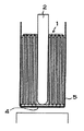
(3) 電極体の底に接続されたリード板を、外装缶の底板に溶着して接続する。このリード板は、図1に示すように、電極体1の中心孔に溶接用電極棒2を挿入して、この電極棒2でリード板4を外装缶5の底板に押し付けて溶接される。
(4) 電極体1の上方に引き出されたリード板3を、外装缶5の開口部を閉塞する封口板の電極に接続し、外装缶に電解液を充填した後、封口板を外装缶の開口部に固定する。外装缶は、封口板で気密に密閉される。
【0003】
以上の工程は、電極体1に接続しているリード板4を、外装缶5の底板に確実に溶接して固定できる特長がある。しかしながら、この構造の電池は、電極体1の中心に、溶接用電極棒よりも太い外径の中心孔を設ける必要があるので、これによって、電極体の実質的な体積が小さくなり、電池の容量が少なくなる。電極体の中心孔を細くして、電池の容量を大きくすることも考えられるが、中心孔が細くなると溶接用電極棒を挿入できないという問題が生じる。
【0004】
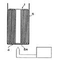
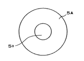
この構造の電池の欠点を解消するために、リード板を外装缶の底板に、外部からレーザー溶接して接続する技術が開発されている(特開平4−162351号公報、特開平8−293299号公報)。これ等の公報に記載される電池は、溶接用電極棒を使用しないで、図2に示すように、外装缶5の底板5Aに外側からレーザー等のエネルギービームを照射する。エネルギービームは、底板5Aとリード板4の一部を溶融して、リード板4を底板5Aに溶接して固定する。
【0005】
【発明が解決しようとする課題】
図2に示すように、外装缶の外部からレーザー光線等のエネルギービームを照射して、リード板を底板に溶着する電池は、電極体に中心孔を設ける必要がない。このため、電極体の実質体積を大きくして、電池の放電容量を大きくできる特長がある。しかしながら、前述したような外装缶の外方からリード板の溶着を行う電池は、リード板を確実に底板に溶着できないことがある。たとえば、電極体を外装缶に入れた状態で、リード板が底板から離れていると、外装缶の底板は溶融されるが、リード板が溶融されず、エネルギービームはリード板を底板に確実に溶着できない状態となる。また、リード板と底板との間に異物があっても、エネルギービームで確実に溶着できなくなる。とくに、この構造の電池は、リード板がどのような状態で、底板に溶着されているかどうか外部からわからず、品質の評価が難しいので、より確実に溶着することが極めて大切である。
【0006】
本発明は、この欠点を解決することを目的に開発されたものである。本発明の重要な目的は、リード板を外装缶に確実に溶着できる電池を提供することにある。
【0007】
【課題を解決するための手段】
本発明の電池は、筒状の外装缶5に電極体1を挿入している。外装缶5に外側から照射されるエネルギービームで、電極体1に接続されたリード板4は、外装缶5の内面に溶着されている。
【0008】
さらに、本発明の請求項1の電池は、外装缶5に、内面に突出する凸部5aを設けており、外装缶5の外側から凸部5aにエネルギービームを照射して、凸部5aの内面にリード板4を溶着している。
【0009】
本発明の請求項2の電池は、外装缶5に設けた凸部5aの突出面を、中央凸に湾曲させ、あるいは円錐状に突出させる形状としている。
【0010】
本発明の請求項3の電池は、リード板4にU字状の切り欠き12を設けて、切り欠き12の内側に弾性変形片4Aを設けている。この弾性変形片4Aが、外装缶5の凸部5aに溶着されている。
【0011】
本発明の請求項4の電池は、弾性変形片4Aを、外装缶5の凸部5aに向かって突出させている。
【0012】
本発明の請求項5の電池は、外装缶5の外側であって、エネルギービームを照射した部分に、防錆塗料6を付着している。請求項6の電池は、防錆塗料6に導電性のあるものを使用している。
【0013】
【発明の実施の形態】
以下、本発明の実施例を図面に基づいて説明する。ただし、以下に示す実施例は、本発明の技術思想を具体化するための電池を例示するものであって、本発明は電池を以下のものに特定しない。
【0014】
さらに、この明細書は、特許請求の範囲を理解しやすいように、実施例に示される部材に対応する番号を、「特許請求の範囲の欄」、および「課題を解決するための手段の欄」に示される部材に付記している。ただ、特許請求の範囲に示される部材を、実施例の部材に特定するものでは決してない。
【0015】
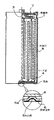
図3に示す電池は、ニッケル−水素電池、ニッケル−カドミウム電池、リチウムイオン電池等の二次電池であって、円筒状の外装缶5と、この外装缶5に挿入している電極体1と、電極体1を外装缶5に接続するリード板3、4とを備える。図に示す電池は、外装缶を円筒状としているが、本発明は、電池の外装缶を円筒状に特定しない。外装缶は、図示しないが、たとえば、四角筒状ないし楕円筒状とすることもできる。
【0016】
外装缶5は鉄製で、その表面をニッケルメッキしている。外装缶5の材質は、電池の種類と特性を考慮して最適な金属が選択される。外装缶5は、例えば、ステンレス、アルミニウム、アルミニウム合金製とすることもある。金属製の外装缶5は、上端の開口部を、封口板7で気密に密閉している。図の封口板7は、外装缶5をかしめる構造で、外装缶に絶縁して固定されている。封口板は、レーザー溶接する等の方法で外装缶に気密に固定することもできる。この構造の封口板は、絶縁して電極を固定する。封口板7は電池の一方の電極を固定している。
【0017】
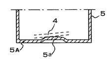
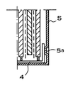
外装缶5は、リード板4を溶接して固定する部分に、図3と図4に示すように、凸部5aを設けている。図に示す電池は、外装缶の底板5Aに凸部5aを設けて、この凸部5aにリード板4を溶着している。外装缶5は、図6の底面図に示すように、底板5Aの中心に凸部5aを設けている。ここに凸部5aを設けている外装缶5は、レーザー溶接のようなエネルギービームでリード板4を溶着する位置を、簡単に、しかも正確に位置決めできる特長がある。外装缶5がどの姿勢に回転していても、エネルギービームでリード板4を溶着する位置が変化しないからである。ただ、凸部は、必ずしも底板の中心に設ける必要はない。また、凸部は、外装缶の底板に設ける必要もなく、たとえば、図7に示すように、外装缶5の周壁に設けることもできる。ただ、凸部をどの位置に設けても、リード板4は凸部5aに溶着される。
【0018】
凸部5aの外径は、溶着する面積を考慮して最適値に設計される。凸部の外径を小さくすると、凸部の先端を確実にリード板に溶着できる。しかしながら、凸部の外径が小さすぎると、リード板と外装缶との溶着面積が小さくなる。
【0019】
凸部5aを外装缶5の内面に高く突出させることは、凸部5aとリード板4の溶着状態を向上させる。ただ、凸部5aを高く突出させることは、外装缶5に挿入される電極体1を押し上げることになる。このため、電極体の高さを低くする必要があって、電極体の実質的な容量を減少させる。
【0020】
凸部5aは、図4の断面図に示すように、突出面を中央凸に湾曲する形状とし、あるいは、図5に示すように、円錐状に突出する形状とする。凸部5aの突出面をこの形状とする電池は、リード板4を隙間なく凸部5aに接触させて、リード板4と凸部5aとをより確実に溶着できる特長がある。ただ、凸部5aは突出面を平面状とすることもできる。
【0021】
電極体1は、正極板と負極板を、セパレータを介して積層している。図3に示す電池は、セパレータを介して互いに積層された正極板と負極板を捲回している。渦巻状の電極体1は、円筒状の外装缶5に挿入される。渦巻状の電極体1は、両側からプレスして楕円形に変形させて、楕円形または角形の外装缶に挿入することができる。さらに、角筒状の外装缶に挿入される電極体は、板状に裁断された複数枚の正極板と負極板を、セパレータを介して積層して製作することもできる。
【0022】
電極体1は、正極板と負極板にリード板3、4を接続している。リード板3、4は、電極体1の上下に配設されて、正極板と負極板とに接続される。電極体1は、図3に示すように、正極板と負極板の芯体を上下に突出させて、突出部をリード板3、4に接続している。図の電極体1は、下方に配設しているリード板4を外装缶5に接続している。電極体1の上方に配設されるリード板3は、封口板7に接続している。
【0023】
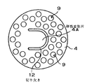
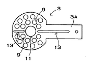
電極体1の上下に接続されるリード板3、4は、図8と図9に示すように、金属板を外装缶5の内形よりも小さい円板状に切断したものである。電極体1の上面に接続されるリード板3は、図9に示すように、外周からリード片3Aを突出させている。リード片3Aは、外装缶5の開口部に絶縁して固定される封口板7に接続される。図9に示す形状のリード板3は、電極体の下面を外装缶の側面に接続するのにも使用できる。
【0024】
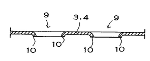
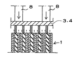
この構造のリード板3、4は、図11の断面図に示すように、溶接用の電極8を介して電極体1に押圧されて、抵抗電気溶接して確実に接続される。図8と図9に示すリード板3、4は、確実に電極体1の電極に電気接続するために、複数の貫通孔9を開口している。リード板3、4に設けた貫通孔9は、図10の拡大断面図に示すように、その周縁に、下方に突出する突起10を設けている。突起10は電極体の電極板に接続させる。さらに、電極体1の上部に接続するリード板3は、図9に示すように、抵抗電気溶接するときの無効電流を少なくするために、中心孔11の両側にスリット13を設けている。
【0025】
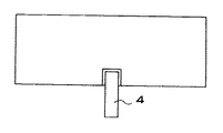
電極体1の下面に連結されるリード板4は、図8に示すように、U字状の切り欠き12を設けて、切り欠き12の内側に弾性変形片4Aを設けている。弾性変形片4Aは、外装缶5の凸部5aに向かって突出している。弾性変形片4Aは、リード板3、4のほぼ中央にあって、外装缶5の凸部5aに溶着される。
【0026】
この構造の電池は、リード板3、4を複数部分で電極体1に接続できるので、大電流特性に優れている。内部抵抗を小さくできるからである。さらに、この構造の電池は、エネルギービームでリード板4を確実に底板5Aに溶着できる特長もある。それは、電極体1を外装缶5に挿入して、リード板4を外装缶の底板5Aの内面に密着できるからである。
【0027】
ただ、本発明の電池は、電極体を外装缶に接続するリード板を、以上の構造に特定しない。リード板は、たとえば、図12に示すように、帯状とすることもできる。このリード板4は、極板の芯体露出部に接続して、電極体1の下方に導出させて、端部を外装缶5の内面に溶着する。また、この構造のリード板4は、図7に示すように、電極体1の側部に導出して、外装缶5の側面に溶着することもできる。
【0028】
リード板4は、外装缶5の内面に溶着される。リード板4を溶着する方法としてはレーザービームや電子ビーム等のエネルギービームを使用する。エネルギービームは、外装缶5とリード板4の両方を溶融して、リード板4を外装缶5に溶着する。
【0029】
レーザービームは、図5に示すように、凸部5aの全体を含む広い領域に照射して、外装缶5とリード板4を溶着する。
【0030】
外装缶5の外面に、レーザー等のエネルギービームを照射すると、外装缶5の表面に付着している耐腐性金属のメッキの効果がなくなる。このため、エネルギービームを照射した部分が腐食しやすくなる。この弊害は、エネルギービームを照射した部分に、図3の要部拡大断面図に示すように、防錆塗料6を塗布して解消できる。外装缶5の底面に防錆塗料6を塗布すると、電池を使用するときに、防錆塗料6が原因で接触不良を起こすことがある。防錆塗料6には、導電性のない有機系の塗料が使用されるからである。この弊害は、防錆塗料6にカーボンや金属粉等の導電材を混合して解消できる。
【0031】
防錆塗料は、霧状にスプレーして塗布し、あるいは、刷毛を使用して塗布できる。さらに、防錆塗料は、細いノズルから噴射するインクジェット方式で塗布することもできる。インクジェット方式は、エネルギービームを照射した正確な位置に正確な厚さに塗布できる特長がある。さらに、防錆塗料は、電池の外装缶に、製造年月日や使用年月日をインクジェットで印刷するときに、一緒に塗布することもできる。
【0032】
【実施例】
[実施例1]
以下の工程でニッケル−カドミウム電池を製造して、リード板が外装缶に接続される状態をテストした。外装缶には、図4に示すように、底面の中央に凸部5aを設けたものを使用した。凸部5aは、突出面を中央凸に湾曲させる形状とした。凸部5aの外径は約2mm、突出高さを0.2mm、突出面の曲率半径を15mmとした。
【0033】
電極体1の底面に接続するリード板4は、図8に示すように、弾性変形片4Aを設けた形状のものを使用した。弾性変形片4Aは、約0.2mm突出させたものを使用した。
【0034】
この構造の外装缶5に、セパレ‐タを介して渦巻き状に巻き取られた電極体であって、両端にリード板3、4を溶着したものを挿入した。リード板3、4には、多数の貫通孔9があり、貫通孔9の周縁に突起10を設けたものを使用した。外装缶に電極体を挿入し、外装缶の底面に設けた凸部5aによる凹部にレーザーを照射して、リード板4を外装缶5に溶着した。この外装缶底面外表面のレーザー溶接部分に塗料として株式会社日立製作所の「JP−K28」を塗布した。電極体の上面に接続しているリード板3を封口板7に溶着した後、電解液を注液して、封口板7で外装缶5の開口部を閉塞してニッケル−カドミウム電池を作製した。
【0035】
[実施例2]
電極体の下面に接続するリード板に、弾性変形片のないものを使用する以外、実施例1と同じようにして、ニッケル−カドミウム電池を試作した。この電池のリード板は、外装缶に溶着する部分を平面状とした。
【0036】
[比較例]
外装缶の底面に凸部を設けない以外、実施例1と同様にしてニッケル−カドミウム電池を試作した。
【0037】
以上のようにして試作した電池のリード板と外装缶の溶着成功率を比較すると以下のようになった。
実施例1の電池…100%
実施例2の電池……98%
比較例の電池………97%
【0038】
以上の試験結果から、本発明の実施例1と実施例2の電池は、リード板と外装缶とが確実に接続された。とくに、実施例1の電池は、リード板と外装缶の溶着不良が皆無になった。
【0039】
【発明の効果】
本発明の電池は、リード板を確実に外装缶に溶着できる特長がある。それは、本発明の電池が、外装缶に凸部を設けて、この凸部にリード板を溶着しているからである。凸部を設けた外装缶は、凸部を確実にリード板に接触できる。このため、凸部に向かってレーザー等のエネルギービームを照射することにより、外装缶をリード板に確実に溶着できる特長がある。とくに、リード板と外装缶とを確実に接触して溶着できる本発明の電池は、衝撃を受けたときにリード板が外装缶が離れるのも確実に防止できる特長がある。
【0040】
本発明の請求項2電池は、凸部の突出面を中央凸に湾曲させ、あるいは、円錐状に突出させているので、凸部をさらに好ましい状態でリード板に接触させて溶着できる。このため、リード板と外装缶との接続状態をさらに改善できる特長がある。
【0041】
さらに、本発明の請求項3の電池は、リード板に弾性変形片を設けて、この弾性変形片を外装缶の凸部に溶着し、さらに、請求項4の電池は、弾性変形片を外装缶の凸部に向かって突出させているので、リード板と外装缶との接続をさらに向上できる特長がある。
【0042】
また、本発明の請求項5の電池は、外装缶の外側であって、エネルギービームを照射した部分に導電性の防錆塗料が付着しているので、エネルギービームを照射した部分が錆るのを有効に阻止できると共に、防錆塗料による接触不良を解消できる特長がある。
【図面の簡単な説明】
【図1】 従来の電池の製造方法を示す断面図
【図2】 従来の電池の製造方法を示す断面図
【図3】 本発明の実施例にかかる電池の断面図
【図4】 図3に示す電池の外装缶の底部を示す断面図
【図5】 本発明の他の実施例にかかる電池の外装缶の底部を示す断面図
【図6】 図4に示す外装缶の底面図
【図7】 本発明の他の実施例にかかる電池の底部を示す断面図
【図8】 図3に示す電池の底部に内蔵されるリード板を示す平面図
【図9】 図3に示す電池の上部に内蔵されるリード板を示す平面図
【図10】 リード板の拡大断面図
【図11】 電極体をリード板に溶着する状態を示す断面図
【図12】 本発明の電池に内蔵される他の構造のリード板を示す正面図
【符号の説明】
1…電極体
2…溶性用電極棒
3…リード板(上のリード板) 3A…リード片
4…リード板(下のリード板) 4A…弾性変形片
5…外装缶 5A…底板 5a…凸部
6…防錆塗料
7…封口板
8…溶接用の電極
9…貫通孔
10…突起
11…中心孔
12…切り欠き
13…スリット[0001]
BACKGROUND OF THE INVENTION
The present invention relates to a battery in which a lead plate connected to an electrode body is welded to the bottom plate of an outer can with an energy beam such as a laser.
[0002]
[Prior art]
A conventional battery in which the lead plate connected to the electrode body is welded to the bottom plate of the outer can is manufactured as follows.
(1) A positive electrode plate and a negative electrode plate are laminated via a separator and wound in a spiral shape to produce an electrode body. In the wound electrode body, a center hole for inserting a welding electrode rod is formed at the center.
(2) The electrode body is inserted into a bottomed cylindrical outer can.
(3) The lead plate connected to the bottom of the electrode body is welded and connected to the bottom plate of the outer can. As shown in FIG. 1, the lead plate is welded by inserting a
(4) The
[0003]
The above process has a feature that the
[0004]
In order to eliminate the drawbacks of the battery having this structure, technologies for connecting the lead plate to the bottom plate of the outer can by laser welding from the outside have been developed (Japanese Patent Laid-Open Nos. Hei 4-162351 and Hei 8-293299). Publication). The batteries described in these publications irradiate the
[0005]
[Problems to be solved by the invention]
As shown in FIG. 2, a battery in which an energy beam such as a laser beam is irradiated from the outside of the outer can and the lead plate is welded to the bottom plate does not need to have a center hole in the electrode body. For this reason, there exists the feature which can enlarge the discharge volume of a battery by enlarging the substantial volume of an electrode body. However, in a battery in which the lead plate is welded from the outside of the outer can as described above, the lead plate may not be reliably welded to the bottom plate. For example, if the lead plate is separated from the bottom plate with the electrode body placed in the outer can, the bottom plate of the outer can is melted, but the lead plate is not melted, and the energy beam reliably attaches the lead plate to the bottom plate. It will be in a state where it cannot be welded. Further, even if there is a foreign substance between the lead plate and the bottom plate, it cannot be reliably welded by the energy beam. In particular, it is extremely important for the battery having this structure to be more reliably welded because it is difficult to assess the quality of the lead plate, since it is difficult to assess the quality of the lead plate from the outside.
[0006]
The present invention has been developed for the purpose of solving this drawback. An important object of the present invention is to provide a battery capable of reliably welding a lead plate to an outer can.
[0007]
[Means for Solving the Problems]
In the battery of the present invention, the
[0008]
Furthermore, in the battery according to
[0009]
In the battery according to
[0010]
In the battery according to
[0011]
In the battery according to
[0012]
In the battery according to
[0013]
DETAILED DESCRIPTION OF THE INVENTION
Embodiments of the present invention will be described below with reference to the drawings. However, the example shown below illustrates the battery for embodying the technical idea of the present invention, and the present invention does not specify the battery as follows.
[0014]
Further, in this specification, in order to facilitate understanding of the scope of claims, the numbers corresponding to the members shown in the examples are referred to as “the scope of claims” and “the means for solving the problems”. It is added to the member shown by. However, the members shown in the claims are not limited to the members in the embodiments.
[0015]
The battery shown in FIG. 3 is a secondary battery such as a nickel-hydrogen battery, a nickel-cadmium battery, or a lithium ion battery, and includes a cylindrical
[0016]
The
[0017]
As shown in FIGS. 3 and 4, the
[0018]
The outer diameter of the
[0019]
Protruding the
[0020]
As shown in the cross-sectional view of FIG. 4, the
[0021]
In the
[0022]
The
[0023]
The
[0024]
As shown in the cross-sectional view of FIG. 11, the
[0025]
Lead
[0026]
The battery having this structure is excellent in large current characteristics because the
[0027]
However, the battery of this invention does not specify the lead plate which connects an electrode body to an exterior can to the above structure. For example, the lead plate may be formed in a strip shape as shown in FIG. The
[0028]
The
[0029]
As shown in FIG. 5, the laser beam is applied to a wide area including the entire
[0030]
When the outer surface of the
[0031]
The rust preventive paint can be applied by spraying in the form of a mist or using a brush. Furthermore, the anticorrosive paint can also be applied by an ink jet method in which it is sprayed from a thin nozzle. The ink jet system has a feature that it can be applied to an accurate position irradiated with an energy beam with an accurate thickness. Further, the rust preventive paint can be applied together on the battery outer can when the date of manufacture and the date of use are printed by inkjet.
[0032]
【Example】
[Example 1]
A nickel-cadmium battery was manufactured in the following steps, and the state in which the lead plate was connected to the outer can was tested. As the outer can, as shown in FIG. 4, one having a
[0033]
As shown in FIG. 8, the
[0034]
An electrode body wound in a spiral shape via a separator and having
[0035]
[Example 2]
A nickel-cadmium battery was prototyped in the same manner as in Example 1 except that a lead plate connected to the lower surface of the electrode body was not provided with an elastic deformation piece. In the lead plate of this battery, the portion welded to the outer can was flat.
[0036]
[Comparative example]
A nickel-cadmium battery was prototyped in the same manner as in Example 1 except that no protrusion was provided on the bottom surface of the outer can.
[0037]
A comparison of the welding success rates of the battery lead plate and the outer can made as described above was as follows.
Battery of Example 1 ... 100%
Battery of Example 2 98%
Battery of comparative example ... 97%
[0038]
From the above test results, in the batteries of Example 1 and Example 2 of the present invention, the lead plate and the outer can were reliably connected. In particular, in the battery of Example 1, there was no poor welding between the lead plate and the outer can.
[0039]
【The invention's effect】
The battery of the present invention has a feature that the lead plate can be reliably welded to the outer can. This is because the battery of the present invention has a convex portion on the outer can, and a lead plate is welded to the convex portion. The outer can provided with the convex portion can reliably contact the convex portion with the lead plate. For this reason, there is an advantage that the outer can can be reliably welded to the lead plate by irradiating an energy beam such as a laser toward the convex portion. In particular, the battery of the present invention, which can reliably weld the lead plate and the outer can to each other, has a feature that can reliably prevent the lead plate from separating from the outer can when subjected to an impact.
[0040]
In the battery according to
[0041]
Furthermore, the battery of
[0042]
Further, in the battery according to
[Brief description of the drawings]
1 is a cross-sectional view showing a conventional battery manufacturing method. FIG. 2 is a cross-sectional view showing a conventional battery manufacturing method. FIG. 3 is a cross-sectional view of a battery according to an embodiment of the present invention. FIG. 5 is a cross-sectional view showing the bottom of the outer can of the battery according to another embodiment of the present invention. FIG. 6 is a bottom view of the outer can shown in FIG. FIG. 8 is a cross-sectional view showing the bottom of a battery according to another embodiment of the present invention. FIG. 8 is a plan view showing a lead plate built in the bottom of the battery shown in FIG. FIG. 10 is an enlarged cross-sectional view of the lead plate. FIG. 11 is a cross-sectional view showing a state in which the electrode body is welded to the lead plate. FIG. 12 is another view of the built-in battery of the present invention. Front view showing the structure lead plate 【Explanation of symbols】
DESCRIPTION OF
Claims (6)
前記外装缶(5)には内面に突出する凸部(5a)を設けており、前記外装缶(5)の外側から前記凸部(5a)にエネルギービームを照射して、前記凸部(5a)の内面にリード板(4)を溶着してなることを特徴とする電池。Electrode body a cylindrical outer can (5) (1) Ri insert and you will said electrode body (1) connected to a lead plate (4) welded to the inner surface of the outer can (5) In batteries,
In the outer Sokan (5) is convex portion projecting on the inner surface of (5a) provided, by irradiating an energy beam from the outside of the outer can (5) on the convex portion (5a), the protrusion ( A battery comprising a lead plate (4) welded to the inner surface of 5a).
Priority Applications (4)
| Application Number | Priority Date | Filing Date | Title |
|---|---|---|---|
| JP24511998A JP3738136B2 (en) | 1998-08-31 | 1998-08-31 | battery |
| US09/384,283 US6379839B1 (en) | 1998-08-31 | 1999-08-27 | Battery having welded lead plate |
| CNB991181689A CN1142604C (en) | 1998-08-31 | 1999-08-30 | Electric battery |
| HK00104405.1A HK1025186B (en) | 1998-08-31 | 2000-07-19 | Battery |
Applications Claiming Priority (1)
| Application Number | Priority Date | Filing Date | Title |
|---|---|---|---|
| JP24511998A JP3738136B2 (en) | 1998-08-31 | 1998-08-31 | battery |
Publications (2)
| Publication Number | Publication Date |
|---|---|
| JP2000077040A JP2000077040A (en) | 2000-03-14 |
| JP3738136B2 true JP3738136B2 (en) | 2006-01-25 |
Family
ID=17128913
Family Applications (1)
| Application Number | Title | Priority Date | Filing Date |
|---|---|---|---|
| JP24511998A Expired - Lifetime JP3738136B2 (en) | 1998-08-31 | 1998-08-31 | battery |
Country Status (3)
| Country | Link |
|---|---|
| US (1) | US6379839B1 (en) |
| JP (1) | JP3738136B2 (en) |
| CN (1) | CN1142604C (en) |
Families Citing this family (44)
| Publication number | Priority date | Publication date | Assignee | Title |
|---|---|---|---|---|
| JP4423699B2 (en) * | 1999-05-27 | 2010-03-03 | ソニー株式会社 | Semiconductor laser device and manufacturing method thereof |
| JP2002352789A (en) * | 2001-05-24 | 2002-12-06 | Shin Kobe Electric Mach Co Ltd | Rechargeable battery |
| US7070881B2 (en) * | 2001-10-18 | 2006-07-04 | Quallion Llc | Electrical battery assembly and method of manufacture |
| US6677076B2 (en) * | 2002-01-15 | 2004-01-13 | Quallion Llc | Electric storage battery construction and method of manufacture |
| US6670071B2 (en) * | 2002-01-15 | 2003-12-30 | Quallion Llc | Electric storage battery construction and method of manufacture |
| JP4605576B2 (en) * | 2002-06-27 | 2011-01-05 | 住友金属工業株式会社 | Bonding material, manufacturing method thereof, bonded product, and manufacturing method thereof |
| JP4321027B2 (en) * | 2002-09-13 | 2009-08-26 | ソニー株式会社 | Non-aqueous electrolyte battery |
| UA58170C2 (en) * | 2002-10-16 | 2006-12-15 | Viktor Oleksandrov Dzenzerskyi | Battery of cylindrical lead-acid accumulators |
| AU2003251798A1 (en) * | 2003-01-15 | 2005-10-07 | Quallion Llc | Battery |
| JP4175975B2 (en) | 2003-07-24 | 2008-11-05 | 三洋電機株式会社 | Battery and manufacturing method thereof |
| JP4359098B2 (en) * | 2003-08-04 | 2009-11-04 | 三洋電機株式会社 | Cylindrical alkaline storage battery |
| JP4654575B2 (en) * | 2003-10-27 | 2011-03-23 | パナソニック株式会社 | Cylindrical battery and inter-battery connection structure using the same |
| JP4484497B2 (en) * | 2003-11-14 | 2010-06-16 | 三洋電機株式会社 | Square sealed secondary battery and manufacturing method thereof |
| JP4641731B2 (en) * | 2004-03-11 | 2011-03-02 | 三洋電機株式会社 | battery |
| US8080329B1 (en) | 2004-03-25 | 2011-12-20 | Quallion Llc | Uniformly wound battery |
| KR100614372B1 (en) * | 2004-06-25 | 2006-08-21 | 삼성에스디아이 주식회사 | Cylindrical Lithium Secondary Battery and Manufacturing Method Thereof |
| JP4404818B2 (en) * | 2004-07-30 | 2010-01-27 | 三星エスディアイ株式会社 | Lithium ion secondary battery |
| KR100601526B1 (en) * | 2004-07-30 | 2006-07-19 | 삼성에스디아이 주식회사 | Lithium-ion Secondary Battery |
| JP4610282B2 (en) * | 2004-09-30 | 2011-01-12 | 三洋電機株式会社 | Battery manufacturing method |
| JP4780954B2 (en) * | 2004-12-07 | 2011-09-28 | 三洋電機株式会社 | Secondary battery |
| US20060263686A1 (en) * | 2005-05-19 | 2006-11-23 | Medtronic, Inc. | Lithium battery manufacturing method |
| KR100778983B1 (en) * | 2006-02-20 | 2007-11-22 | 삼성에스디아이 주식회사 | Can for cylindrical lithium secondary battery and cylindrical lithium secondary battery using same |
| US8092934B2 (en) * | 2006-03-24 | 2012-01-10 | Maxwell Technologies, Inc. | Energy storage device having a collector plate |
| KR20090012262A (en) * | 2006-05-09 | 2009-02-02 | 발렌스 테크놀로지, 인코포레이티드 | Secondary electrochemical cell with increased current collection efficiency |
| JP2008251192A (en) * | 2007-03-29 | 2008-10-16 | Sanyo Electric Co Ltd | Battery manufacturing method |
| KR100889529B1 (en) * | 2007-04-20 | 2009-03-19 | 삼성에스디아이 주식회사 | Secondary battery |
| KR100965683B1 (en) * | 2008-03-31 | 2010-06-24 | 삼성에스디아이 주식회사 | Battery pack |
| KR100971342B1 (en) * | 2008-06-03 | 2010-07-20 | 삼성에스디아이 주식회사 | Lithium polymer battery |
| US8703327B2 (en) | 2008-06-20 | 2014-04-22 | Samsung Sdi Co., Ltd. | Rechargeable battery and manufacturing method thereof |
| JP5348968B2 (en) * | 2008-08-22 | 2013-11-20 | 三洋電機株式会社 | Cylindrical battery |
| KR101737644B1 (en) * | 2008-11-25 | 2017-05-18 | 에이일이삼 시스템즈, 엘엘씨 | Method and design for externally applied laser welding of internal connections in a high power electrochemical cell |
| KR20110124269A (en) | 2009-02-09 | 2011-11-16 | 바르타 미크로바테리 게엠베하 | Button batteries and how to make them |
| KR101023865B1 (en) * | 2009-02-25 | 2011-03-22 | 에스비리모티브 주식회사 | Secondary battery |
| DE102009060800A1 (en) | 2009-06-18 | 2011-06-09 | Varta Microbattery Gmbh | Button cell with winding electrode and method for its production |
| CN102371447A (en) * | 2010-08-13 | 2012-03-14 | 北汽福田汽车股份有限公司 | Welding positioning method and cover panel of vehicle |
| JP5492125B2 (en) * | 2011-03-24 | 2014-05-14 | 株式会社東芝 | Secondary battery and method for manufacturing secondary battery |
| US9088120B2 (en) | 2011-06-28 | 2015-07-21 | GM Global Technology Operations LLC | Serviceable electrical connection and method |
| JP2015170395A (en) * | 2014-03-05 | 2015-09-28 | 日立オートモティブシステムズ株式会社 | cylindrical secondary battery |
| JP2015202513A (en) * | 2014-04-15 | 2015-11-16 | シロキ工業株式会社 | Laser welding method for metal plate laminate and method for manufacturing vehicle door frame using laser welding method for metal plate laminate |
| DE102016105696A1 (en) * | 2016-03-29 | 2017-10-19 | Epcos Ag | electrolytic capacitor |
| KR102662717B1 (en) | 2017-09-20 | 2024-05-03 | 주식회사 엘지에너지솔루션 | Cylindrical Secondary Battery Consisting of Curved Bottom |
| JP7080197B2 (en) * | 2019-02-26 | 2022-06-03 | 株式会社豊田自動織機 | Power storage module and manufacturing method of power storage module |
| KR102650470B1 (en) | 2021-06-30 | 2024-03-22 | 삼성에스디아이 주식회사 | Secondary battery |
| CN114937855B (en) * | 2022-03-30 | 2024-05-14 | 江苏正力新能电池技术有限公司 | Preparation method of cylindrical battery and cylindrical battery |
Family Cites Families (7)
| Publication number | Priority date | Publication date | Assignee | Title |
|---|---|---|---|---|
| DE2814905C2 (en) * | 1978-04-06 | 1982-12-30 | Brown, Boveri & Cie Ag, 6800 Mannheim | Electrochemical storage cell or battery |
| US4767682A (en) * | 1987-09-11 | 1988-08-30 | Eveready Battery Company | Method for assembling a cell employing a coiled electrode assembly |
| JP2937456B2 (en) | 1990-10-25 | 1999-08-23 | 東芝電池株式会社 | Manufacturing method of cylindrical battery |
| JP3059842B2 (en) * | 1992-11-16 | 2000-07-04 | 三洋電機株式会社 | Non-aqueous electrolyte battery |
| JPH08293299A (en) | 1995-04-24 | 1996-11-05 | Matsushita Electric Ind Co Ltd | Battery manufacturing method |
| US5916707A (en) * | 1995-11-15 | 1999-06-29 | Sony Corporation | Nonaqueous-electrolyte secondary battery and battery case for limiting expansion thereof due to internal pressure |
| JP3210593B2 (en) * | 1997-02-17 | 2001-09-17 | 日本碍子株式会社 | Lithium secondary battery |
-
1998
- 1998-08-31 JP JP24511998A patent/JP3738136B2/en not_active Expired - Lifetime
-
1999
- 1999-08-27 US US09/384,283 patent/US6379839B1/en not_active Expired - Lifetime
- 1999-08-30 CN CNB991181689A patent/CN1142604C/en not_active Expired - Lifetime
Also Published As
| Publication number | Publication date |
|---|---|
| US6379839B1 (en) | 2002-04-30 |
| HK1025186A1 (en) | 2000-11-03 |
| US20020034680A1 (en) | 2002-03-21 |
| CN1246734A (en) | 2000-03-08 |
| JP2000077040A (en) | 2000-03-14 |
| CN1142604C (en) | 2004-03-17 |
Similar Documents
| Publication | Publication Date | Title |
|---|---|---|
| JP3738136B2 (en) | battery | |
| EP4160778B1 (en) | Pole and electrode current collecting disc assembly structure, and battery | |
| US8603670B2 (en) | Secondary battery | |
| CN117157790A (en) | Cylindrical secondary battery cell | |
| EP0798794B1 (en) | A cell which secures the reliability of a protective circuit | |
| CN114267910B (en) | Electrochemical cell with contact strips | |
| JP5378366B2 (en) | Cap assembly for high current capacity energy supply equipment | |
| KR100601526B1 (en) | Lithium-ion Secondary Battery | |
| JP3825659B2 (en) | Secondary battery | |
| KR102824566B1 (en) | Cylindrical secondary battery | |
| EP4531198A1 (en) | Current collecting plate and battery unit comprising current collecting plate | |
| EP1139463B1 (en) | Method and apparatus for manufacturing battery module and unit battery cell for use in battery module | |
| JP4780954B2 (en) | Secondary battery | |
| US6979514B2 (en) | Collector used for an alkali storage battery | |
| JP4373049B2 (en) | Storage battery | |
| EP4593165A1 (en) | Cylindrical secondary battery | |
| CN220574982U (en) | Ultrasonic welding equipment | |
| JP5157049B2 (en) | Sealed battery, method for manufacturing the same, assembled battery including a plurality of sealed batteries, and method for manufacturing the same | |
| KR100601522B1 (en) | Lithium-ion Secondary Battery | |
| JP2000348709A (en) | Battery and manufacturing method thereof | |
| JP2022092680A (en) | Sealed battery and method of manufacturing sealed battery | |
| KR100601524B1 (en) | Lithium-ion Secondary Battery | |
| JP3540591B2 (en) | Storage battery and method of manufacturing the same | |
| JP2000195496A (en) | Alkaline storage battery | |
| CN219759900U (en) | Battery and battery pack |
Legal Events
| Date | Code | Title | Description |
|---|---|---|---|
| A977 | Report on retrieval |
Free format text: JAPANESE INTERMEDIATE CODE: A971007 Effective date: 20040811 |
|
| A131 | Notification of reasons for refusal |
Free format text: JAPANESE INTERMEDIATE CODE: A131 Effective date: 20050222 |
|
| A131 | Notification of reasons for refusal |
Free format text: JAPANESE INTERMEDIATE CODE: A131 Effective date: 20050705 |
|
| A521 | Request for written amendment filed |
Free format text: JAPANESE INTERMEDIATE CODE: A523 Effective date: 20050902 |
|
| TRDD | Decision of grant or rejection written | ||
| A01 | Written decision to grant a patent or to grant a registration (utility model) |
Free format text: JAPANESE INTERMEDIATE CODE: A01 Effective date: 20051004 |
|
| A61 | First payment of annual fees (during grant procedure) |
Free format text: JAPANESE INTERMEDIATE CODE: A61 Effective date: 20051031 |
|
| FPAY | Renewal fee payment (event date is renewal date of database) |
Free format text: PAYMENT UNTIL: 20091104 Year of fee payment: 4 |
|
| FPAY | Renewal fee payment (event date is renewal date of database) |
Free format text: PAYMENT UNTIL: 20101104 Year of fee payment: 5 |
|
| FPAY | Renewal fee payment (event date is renewal date of database) |
Free format text: PAYMENT UNTIL: 20111104 Year of fee payment: 6 |
|
| FPAY | Renewal fee payment (event date is renewal date of database) |
Free format text: PAYMENT UNTIL: 20111104 Year of fee payment: 6 |
|
| FPAY | Renewal fee payment (event date is renewal date of database) |
Free format text: PAYMENT UNTIL: 20121104 Year of fee payment: 7 |
|
| FPAY | Renewal fee payment (event date is renewal date of database) |
Free format text: PAYMENT UNTIL: 20131104 Year of fee payment: 8 |
|
| EXPY | Cancellation because of completion of term |