JP2009526264A - Encoding / decoding apparatus and method - Google Patents
Encoding / decoding apparatus and method Download PDFInfo
- Publication number
- JP2009526264A JP2009526264A JP2008554141A JP2008554141A JP2009526264A JP 2009526264 A JP2009526264 A JP 2009526264A JP 2008554141 A JP2008554141 A JP 2008554141A JP 2008554141 A JP2008554141 A JP 2008554141A JP 2009526264 A JP2009526264 A JP 2009526264A
- Authority
- JP
- Japan
- Prior art keywords
- domain
- downmix signal
- signal
- information
- rendering
- Prior art date
- Legal status (The legal status is an assumption and is not a legal conclusion. Google has not performed a legal analysis and makes no representation as to the accuracy of the status listed.)
- Pending
Links
Images


Classifications
-
- G—PHYSICS
- G10—MUSICAL INSTRUMENTS; ACOUSTICS
- G10L—SPEECH ANALYSIS OR SYNTHESIS; SPEECH RECOGNITION; SPEECH OR VOICE PROCESSING; SPEECH OR AUDIO CODING OR DECODING
- G10L19/00—Speech or audio signals analysis-synthesis techniques for redundancy reduction, e.g. in vocoders; Coding or decoding of speech or audio signals, using source filter models or psychoacoustic analysis
- G10L19/008—Multichannel audio signal coding or decoding using interchannel correlation to reduce redundancy, e.g. joint-stereo, intensity-coding or matrixing
-
- G—PHYSICS
- G10—MUSICAL INSTRUMENTS; ACOUSTICS
- G10L—SPEECH ANALYSIS OR SYNTHESIS; SPEECH RECOGNITION; SPEECH OR VOICE PROCESSING; SPEECH OR AUDIO CODING OR DECODING
- G10L19/00—Speech or audio signals analysis-synthesis techniques for redundancy reduction, e.g. in vocoders; Coding or decoding of speech or audio signals, using source filter models or psychoacoustic analysis
- G10L19/04—Speech or audio signals analysis-synthesis techniques for redundancy reduction, e.g. in vocoders; Coding or decoding of speech or audio signals, using source filter models or psychoacoustic analysis using predictive techniques
- G10L19/16—Vocoder architecture
- G10L19/167—Audio streaming, i.e. formatting and decoding of an encoded audio signal representation into a data stream for transmission or storage purposes
-
- G—PHYSICS
- G10—MUSICAL INSTRUMENTS; ACOUSTICS
- G10L—SPEECH ANALYSIS OR SYNTHESIS; SPEECH RECOGNITION; SPEECH OR VOICE PROCESSING; SPEECH OR AUDIO CODING OR DECODING
- G10L19/00—Speech or audio signals analysis-synthesis techniques for redundancy reduction, e.g. in vocoders; Coding or decoding of speech or audio signals, using source filter models or psychoacoustic analysis
- G10L19/04—Speech or audio signals analysis-synthesis techniques for redundancy reduction, e.g. in vocoders; Coding or decoding of speech or audio signals, using source filter models or psychoacoustic analysis using predictive techniques
- G10L19/16—Vocoder architecture
- G10L19/18—Vocoders using multiple modes
- G10L19/24—Variable rate codecs, e.g. for generating different qualities using a scalable representation such as hierarchical encoding or layered encoding
-
- G—PHYSICS
- G11—INFORMATION STORAGE
- G11B—INFORMATION STORAGE BASED ON RELATIVE MOVEMENT BETWEEN RECORD CARRIER AND TRANSDUCER
- G11B20/00—Signal processing not specific to the method of recording or reproducing; Circuits therefor
- G11B20/10—Digital recording or reproducing
-
- H—ELECTRICITY
- H03—ELECTRONIC CIRCUITRY
- H03M—CODING; DECODING; CODE CONVERSION IN GENERAL
- H03M7/00—Conversion of a code where information is represented by a given sequence or number of digits to a code where the same, similar or subset of information is represented by a different sequence or number of digits
- H03M7/30—Compression; Expansion; Suppression of unnecessary data, e.g. redundancy reduction
-
- H—ELECTRICITY
- H04—ELECTRIC COMMUNICATION TECHNIQUE
- H04S—STEREOPHONIC SYSTEMS
- H04S3/00—Systems employing more than two channels, e.g. quadraphonic
- H04S3/008—Systems employing more than two channels, e.g. quadraphonic in which the audio signals are in digital form, i.e. employing more than two discrete digital channels
-
- H—ELECTRICITY
- H04—ELECTRIC COMMUNICATION TECHNIQUE
- H04S—STEREOPHONIC SYSTEMS
- H04S5/00—Pseudo-stereo systems, e.g. in which additional channel signals are derived from monophonic signals by means of phase shifting, time delay or reverberation
-
- H—ELECTRICITY
- H04—ELECTRIC COMMUNICATION TECHNIQUE
- H04S—STEREOPHONIC SYSTEMS
- H04S2420/00—Techniques used stereophonic systems covered by H04S but not provided for in its groups
- H04S2420/01—Enhancing the perception of the sound image or of the spatial distribution using head related transfer functions [HRTF's] or equivalents thereof, e.g. interaural time difference [ITD] or interaural level difference [ILD]
-
- H—ELECTRICITY
- H04—ELECTRIC COMMUNICATION TECHNIQUE
- H04S—STEREOPHONIC SYSTEMS
- H04S2420/00—Techniques used stereophonic systems covered by H04S but not provided for in its groups
- H04S2420/03—Application of parametric coding in stereophonic audio systems
Abstract
【課題】マルチチャンネル信号を3D効果を有する信号に效率的に符号化でき、再生環境によって適応的に最上の音質を有するオーディオ信号を復元して再生できる符号化/復号化方法及び装置を提供する。
【解決手段】ビットストリームから、第1のマルチチャンネルデコーダに最適化した互換型ダウンミックス信号を抽出する段階と、互換型ダウンミックス信号を、第2のマルチチャンネルデコーダに最適化したダウンミックス信号に変換する互換処理段階と、変換されたダウンミックス信号に3Dレンダリングを行い、3Dダウンミックス信号を生成する段階と、を含むことを特徴とする復号化方法を提供する。
【選択図】図1Provided is an encoding / decoding method and apparatus capable of efficiently encoding a multi-channel signal into a signal having a 3D effect and restoring and reproducing an audio signal having the best sound quality adaptively according to a reproduction environment. .
Extracting a compatible downmix signal optimized for a first multichannel decoder from a bitstream, and converting the compatible downmix signal into a downmix signal optimized for a second multichannel decoder There is provided a decoding method comprising: a compatibility processing step of converting; and a step of performing 3D rendering on the converted downmix signal to generate a 3D downmix signal.
[Selection] Figure 1
Description
本発明は、符号化/復号化方法及び装置に係り、より詳細には、3D効果を有する信号の処理のためのオーディオ信号の符号化/復号化装置及びこれを用いた符号化/復号化方法に関する。 The present invention relates to an encoding / decoding method and apparatus, and more particularly, an audio signal encoding / decoding apparatus for processing a signal having a 3D effect, and an encoding / decoding method using the same. About.
マルチチャンネル信号は、符号化装置を通じて自分よりも少ない数のチャンネルを有する信号にダウンミックスされて復号化装置に転送され、復号化装置は、前記転送されてきたダウンミックス信号をマルチチャンネル信号に復元した後、3以上のスピーカ、例えば、5.1チャンネルのスピーカを用いて再生する。 The multi-channel signal is down-mixed to a signal having a smaller number of channels than itself through the encoding device and transferred to the decoding device, and the decoding device restores the transferred down-mix signal to the multi-channel signal. Then, playback is performed using three or more speakers, for example, 5.1 channel speakers.
また、マルチチャンネル信号はヘッドホンのような2チャンネルのスピーカを通じて再生されることもできる。この場合、使用者に、2チャンネルスピーカの音を3以上の音源から出力されるかのように感じさせるには、マルチチャンネル信号を3D効果を有する信号に符号化または復号化する3D処理技術が必要である。 The multi-channel signal can also be reproduced through a two-channel speaker such as headphones. In this case, in order to make the user feel as if the sound of the 2-channel speaker is output from three or more sound sources, a 3D processing technique for encoding or decoding a multi-channel signal into a signal having a 3D effect is used. is necessary.
本発明の目的は、様々な再生環境でマルチチャンネル信号を再生できるように、3D効果を有する信号を效率的に処理することができる符号化/復号化装置及び方法を提供することにある。 An object of the present invention is to provide an encoding / decoding apparatus and method capable of efficiently processing a signal having a 3D effect so that a multi-channel signal can be reproduced in various reproduction environments.
上記の目的を達成するための本発明による復号化方法は、ビットストリームから、第1のマルチチャンネルデコーダに最適化した互換型ダウンミックス信号を抽出する段階と、前記互換型ダウンミックス信号を第2のマルチチャンネルデコーダに最適化したダウンミックス信号に変換する互換処理段階と、前記変換されたダウンミックス信号に3Dレンダリングを行い、3Dダウンミックス信号を生成する段階と、を有することを特徴とする。 According to another aspect of the present invention, there is provided a decoding method for extracting a compatible downmix signal optimized for a first multi-channel decoder from a bitstream; The method includes a compatibility processing step of converting into a downmix signal optimized for the multi-channel decoder, and a step of performing 3D rendering on the converted downmix signal to generate a 3D downmix signal.
上記の目的を達成するための本発明による他の復号化方法は、ビットストリームから、第1のマルチチャンネルデコーダに最適化した互換型ダウンミックス信号を抽出する段階と、3Dレンダリングに用いられるフィルタ情報に、前記互換型ダウンミックス信号の変換のための互換情報を合成する段階と、前記合成されたフィルタ情報を用いて前記互換型ダウンミックス信号に3Dレンダリングを行い、3Dダウンミックス信号を生成する段階と、を有することを特徴とする。 To achieve the above object, another decoding method according to the present invention includes extracting a compatible downmix signal optimized for a first multi-channel decoder from a bitstream, and filter information used for 3D rendering. In addition, synthesizing compatible information for converting the compatible downmix signal, and performing 3D rendering on the compatible downmix signal using the synthesized filter information to generate a 3D downmix signal It is characterized by having.
上記の目的を達成するための本発明による復号化装置は、ビットストリームから、第1のマルチチャンネルデコーダに最適化した互換型ダウンミックス信号を抽出するビットアンパッキング部と、互換情報を用いて前記互換型ダウンミックス信号を第2のマルチチャンネルデコーダに最適化したダウンミックス信号に変換するダウンミックス互換処理部と、前記変換されたダウンミックス信号に3Dレンダリングを行い、3Dダウンミックス信号を生成する3Dレンダリング部と、を有することを特徴とする。 To achieve the above object, a decoding apparatus according to the present invention uses a bit unpacking unit that extracts a compatible downmix signal optimized for a first multi-channel decoder from a bitstream, and uses the compatibility information to A downmix compatible processing unit that converts a compatible downmix signal into a downmix signal optimized for a second multi-channel decoder, and 3D that performs 3D rendering on the converted downmix signal to generate a 3D downmix signal And a rendering unit.
前記復号化方法は、好ましくは、コンピュータで実行させるためのプログラムを記録した、コンピュータで読み取り可能な記録媒体で具現化できる。 Preferably, the decoding method can be embodied by a computer-readable recording medium on which a program to be executed by a computer is recorded.
本発明の符号化/復号化装置及び方法によれば、マルチチャンネル信号を3D効果を有する信号に效率的に符号化でき、再生環境によって適応的に最上の音質を有するオーディオ信号を復元して再生することが可能になる。 According to the encoding / decoding apparatus and method of the present invention, a multi-channel signal can be efficiently encoded into a signal having a 3D effect, and an audio signal having the best sound quality is adaptively restored according to a reproduction environment and reproduced. It becomes possible to do.
以下、添付の図面を参照しつつ、本発明に係る符号化/復号化方法及び装置の好適な実施例について詳細に説明する。 Hereinafter, preferred embodiments of an encoding / decoding method and apparatus according to the present invention will be described in detail with reference to the accompanying drawings.
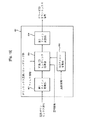
図1は、本発明の一実施例による符号化/復号化装置を示すブロック図である。図1を参照すると、符号化器100は、マルチチャンネルエンコーダ110、3Dレンダリング部120、ダウンミックスエンコーダ130及びビットパッキング部140を含んでなる。
FIG. 1 is a block diagram illustrating an encoding / decoding apparatus according to an embodiment of the present invention. Referring to FIG. 1, the
マルチチャンネルエンコーダ110は、複数のチャンネルを有するマルチチャンネル信号をステレオまたはモノラルのダウンミックス信号にダウンミックスし、また、前記ダウンミックス信号からマルチチャンネル信号を復元するのに必要な複数の前記チャンネルに関する空間情報(spatial information)を生成する。
The
空間情報は、マルチチャンネルのうち、2チャンネル間のエネルギー差を示すCLD(Channel Level Difference)、2チャンネル信号から3チャンネル信号を生成するために用いられる予測係数であるCPC(Channel Prediction Coefficient)、2チャンネル間相関関係(correlation)を示すICC(Inter Channel Correlation)、及び2チャンネル間時間差を示すCTD(Channel Time Difference)などを含むことができる。 Spatial information includes CLD (Channel Level Difference) indicating an energy difference between two channels among multi-channels, CPC (Channel Prediction Coefficient), which is a prediction coefficient used to generate a three-channel signal from a two-channel signal, and 2 An ICC (Inter Channel Correlation) indicating a correlation between channels and a CTD (Channel Time Difference) indicating a time difference between two channels can be included.
3Dレンダリング部120は、ダウンミックス信号を用いて3Dダウンミックス信号を生成する。3Dダウンミックス信号は、2チャンネルの信号が3以上の方向性を有するようにし、ヘッドホンのような2チャンネルスピーカを通じて3次元立体音響を再生できるようにするための信号である。すなわち、3Dダウンミックス信号を2チャンネルのスピーカを通じて再生すると、再生される音は3チャンネル以上の音源から出力されるかのように使用者に聞こえさせることができる。音原の方向感は、両耳から入ってくる音の強度差、時間差、位相差のうち少なくとも一つにより形成されるので、3Dレンダリング部120は、上記のように人間が聴覚で音原の3次元上の位置を把握するメカニズムを用いてダウンミックス信号を3Dダウンミックス信号に変換することができる。 The 3D rendering unit 120 generates a 3D downmix signal using the downmix signal. The 3D downmix signal is a signal for allowing a two-channel signal to have a directionality of 3 or more and reproducing a three-dimensional stereophonic sound through a two-channel speaker such as a headphone. That is, when a 3D downmix signal is reproduced through a two-channel speaker, the reproduced sound can be heard by the user as if it is output from a sound source having three or more channels. Since the direction of the sound source is formed by at least one of the intensity difference, time difference, and phase difference of sounds coming from both ears, the 3D rendering unit 120 can detect the sound source by hearing as described above. A downmix signal can be converted into a 3D downmix signal using a mechanism for grasping a position in three dimensions.
3Dレンダリング部120は、フィルタを用いてダウンミックス信号をフィルタリングすることによって3Dダウンミックス信号を生成することが好ましく、フィルタに関する情報、例えば、フィルタの係数は外部から入力されることができる。また、3Dレンダリング部120は、ダウンミックス信号を用いて3Dダウンミックス信号を生成すべく、マルチチャンネルエンコーダ110で生成された空間情報を用いても良い。例えば、3Dレンダリング部120は、空間情報を用いてダウンミックス信号を仮想のマルチチャンネル信号に変換した後、この仮想のマルチチャンネル信号をフィルタリングし、3Dダウンミックス信号に変換することができる。
The 3D rendering unit 120 may generate a 3D downmix signal by filtering the downmix signal using a filter, and information about the filter, for example, the coefficient of the filter, may be input from the outside. Further, the 3D rendering unit 120 may use the spatial information generated by the
3Dレンダリング部120は、HRTF(Head Related Transfer Function)フィルタを用いてダウンミックス信号をフィルタリングすることによって、3Dダウンミックス信号を生成できる。 The 3D rendering unit 120 can generate a 3D downmix signal by filtering the downmix signal using an HRTF (Head Related Transfer Function) filter.
HRTFは、任意の位置を有する音源から出る音波と耳の鼓膜に到達する音波間の伝達関数(transfer function)を意味し、音原の方位と高度によってその値は異なる。方向性のない信号をHRTFでフィルタリングすると、人には、あたかも特定方向から音が出るかのように聞こえる。 HRTF means a transfer function between a sound wave emitted from a sound source having an arbitrary position and a sound wave reaching the ear tympanic membrane, and its value varies depending on the direction and altitude of the sound source. When a signal with no directionality is filtered by HRTF, it sounds to a person as if sound is coming from a specific direction.
3Dレンダリング部120は、周波数ドメイン、例えば、DFT(Discrete Fourier Transform)ドメインまたはFFT(Fast Fourier Transform)ドメイン上で3Dダウンミックス信号生成作業を行うことができる。この場合、3Dプロセシングの前にDFTまたはFFTを行ったり、3Dプロセシングの後にIDFT(inverse DFT)またはIFFT(inverse FFT)を行うことができる。 The 3D rendering unit 120 may perform a 3D downmix signal generation operation on a frequency domain, for example, a DFT (Discrete Fourier Transform) domain or an FFT (Fast Fourier Transform) domain. In this case, DFT or FFT can be performed before 3D processing, or IDFT (inverse DFT) or IFFT (inverse FFT) can be performed after 3D processing.
3Dレンダリング部120は、QMF(quadrature mirror Filter)/ハイブリッドドメイン上でも3Dレンダリングを行うことができ、その場合、3Dレンダリングの前後にQMF/ハイブリッド分析及び合成(synthesis)が行われるこどかできる。 The 3D rendering unit 120 can perform 3D rendering even on a quadrature mirror filter (QMF) / hybrid domain. In this case, QMF / hybrid analysis and synthesis can be performed before and after the 3D rendering.
また、3Dレンダリングは、時間(time)ドメイン上でも行われることができる。3Dレンダリングの行われるドメインは、要求される音質、装置の演算能力などを考慮して最も好適なドメインを決定すれば良い。 3D rendering can also be performed on the time domain. The most suitable domain may be determined as the domain in which 3D rendering is performed in consideration of the required sound quality, the computing capability of the apparatus, and the like.
ダウンミックスエンコーダ130は、マルチチャンネルエンコーダ110から出力されるダウンミックス信号または3Dレンダリング部120から出力される3Dダウンミックス信号を符号化する。ダウンミックスエンコーダ130は、入力されるダウンミックス信号をAAC(Advanced Audio Coding)、MP3(MPEG layer 3)またはBSAC(Bit Sliced Arithmetic Coding)などのオーディオ信号コーディング方法を用いて符号化することができる。
The
ダウンミックスエンコーダ130は、3D処理されなかったダウンミックス信号と3D処理された3Dダウンミックス信号とも符号化することができ、この場合、転送されるビットストリームにこれらの両信号を全て含めることができる。
ビットパッキング部140は、符号化されたダウンミックス信号または3Dダウンミックス信号と空間情報を用いてビットストリームを生成する。
The
ビットストリームは、空間情報、含まれた信号がダウンミックス信号か3Dダウンミックス信号かを示すダウンミックス識別情報、3Dレンダリング部120で用いられたフィルタに関する情報、例えば、HRTF係数に関する情報などを含むことができる。 The bitstream includes spatial information, downmix identification information indicating whether the included signal is a downmix signal or a 3D downmix signal, information about a filter used in the 3D rendering unit 120, for example, information about an HRTF coefficient, and the like. Can do.
すなわち、復号化装置に転送されるビットストリームには、3D処理されなかったダウンミックス信号とエンコーダで3D処理されたエンコーダ3Dダウンミックス信号のうち少なくとも一つが含まれることができ、転送されたビットストリームに含まれたダウンミックス信号を復号化装置で識別できるようにするダウンミックス識別情報が含まれることが好ましい。
That is, the bitstream transferred to the decoding apparatus can include at least one of a downmix signal that has not been 3D processed and an
転送されるビットストリームにダウンミックス信号とエンコーダ3Dダウンミックス信号のうちのいずれかが含まれるかは、使用者の選択、符号化/復号化装置の性能、再生環境などによって決定されることができる。
Whether a bitstream to be transferred includes a downmix signal or an
HRTF係数に対する情報は、3Dレンダリング部120で使用されたHRTFの逆変換関数の係数を含むことができ、3Dレンダリング部120で使用されたHRTFの係数に関する簡略化した情報、例えば、前記係数の包絡線(envelope)情報のみを含んでも良い。ビットストリームにHRTF逆変換関数の係数を含めて転送する場合、復号化装置のHRTF係数変換作業が省略されることができるので、復号化装置の演算量を減少させることができる。 The information on the HRTF coefficient may include a coefficient of the inverse transform function of the HRTF used in the 3D rendering unit 120, and simplified information on the coefficient of the HRTF used in the 3D rendering unit 120, for example, an envelope of the coefficient Only envelope information may be included. When transferring the bitstream including the coefficient of the HRTF inverse transform function, the HRTF coefficient conversion work of the decoding device can be omitted, so that the amount of calculation of the decoding device can be reduced.
ビットストリームは、HRTFを用いたフィルタリングによる信号のエネルギー変化に関する情報、すなわち、フィルタリング前の信号のエネルギーとフィルタリング後の信号のエネルギー間の差または比に関する情報を含むことができる。 The bitstream may include information on the energy change of the signal due to filtering using HRTF, i.e. information on the difference or ratio between the energy of the signal before filtering and the energy of the signal after filtering.
ビットストリームは、HRTF係数を含むか否かを示す情報を有することができ、HRTF係数がビットストリームに含まれた場合、3Dレンダリング部120で使用されたHRTFの係数とHRTFの逆変換関数の係数のうちいずれかを含んでいるかに関する情報を有することができる。 The bitstream may have information indicating whether or not to include an HRTF coefficient. When the HRTF coefficient is included in the bitstream, the coefficient of the HRTF used in the 3D rendering unit 120 and the coefficient of the inverse conversion function of the HRTF Information on whether one of the two is included.
図1を参照すると、本発明による復号化装置は、ビットアンパッキング部210、ダウンミックスデコーダ220、3Dレンダリング部230及びマルチチャンネルデコーダ240を含んでなる。
Referring to FIG. 1, the decoding apparatus according to the present invention includes a bit
ビットアンパッキング部210は、入力されるビットストリームから、符号化されたダウンミックス信号と空間情報を抽出し、ダウンミックスデコーダ220は、符号化されたダウンミックス信号を復号化する。ダウンミックスデコーダ220は、AAC、MP3またはBSACなどのオーディオ信号復号化方法を用いて、符号化されたダウンミックス信号を復号化することができる。
The bit
上記のように、ビットストリームから抽出される信号は、符号化されたダウンミックス信号または符号化されたエンコーダ3Dダウンミックス信号でありうる。ビットストリームに含まれたダウンミックス信号が3D処理された信号か否かに関する情報は、ビットストリームに含まれることができる。
As described above, the signal extracted from the bitstream can be an encoded downmix signal or an encoded
ダウンミックスデコーダ220により復号化されたエンコーダ3Dダウンミックス信号は、直ちに再生可能である。
The
ダウンミックスデコーダ220により復号化されたダウンミックス信号は、3Dレンダリング部230に含まれた第3のレンダリング部233で3D効果処理され、3Dダウンミックス信号に変換されることができる。このように復号化装置で3D効果処理されたデコーダ3Dダウンミックス信号は、直ちに再生可能である。
The downmix signal decoded by the
3Dレンダリング部230に含まれた第1のレンダリング部231は、ダウンミックスデコーダ220により復号化されたエンコーダ3Dダウンミックス信号に3Dレンダリングを行い、ダウンミックス信号を生成する。例えば、第1のレンダリング部231は、エンコーダ3Dダウンミックス信号の3D効果を除去することによって、3D処理されなかったダウンミックス信号を生成できる。
The
エンコーダ3Dダウンミックス信号の3D効果は、第1のレンダリング部231により完全に除去されないこともあり、したがって、第1のレンダリング部231から出力されるダウンミックス信号は、若干の3D効果を有する信号にもなりうる。
The 3D effect of the
第1のレンダリング部231は、符号化器100の3Dレンダリング部120で使用されたフィルタの逆変換フィルタを用いて、エンコーダダウンミックス信号を3D効果の除去されたダウンミックス信号に変換できる。3Dレンダリング部120で使用されたフィルタまたは逆変換フィルタに関する情報は、符号化器100から転送されるビットストリームに含まれることができる。
The
ここで、フィルタはHRTFフィルタとすることが好ましく、この場合、符号化器100で使用されたHRTFの係数またはHRTFの逆変換係数は、符号化器100から転送されるビットストリームに含まれることができる。符号化器100で使用されたHRTFの係数は逆変換された後、第1のレンダリング部231の3Dレンダリングに用いられる。ビットストリームに符号化器100で使用されたHRTFの逆変換係数が含まれた場合、逆変換過程無しで、該ビットストリームに含まれた係数を用いて3Dレンダリングを行うことができるので、復号化装置の演算量を減少させることができる。
Here, the filter is preferably an HRTF filter. In this case, the HRTF coefficient used in the
入力されるビットストリームには、フィルタ情報、例えば、HRTF係数を含むか否かを示す情報またはビットストリームに含まれたフィルタ情報が逆変換されたか否かに関する情報が含まれることができる。 The input bitstream can include filter information, for example, information indicating whether or not the HRTF coefficient is included or information regarding whether or not the filter information included in the bitstream has been inversely converted.
マルチチャンネルデコーダ240は、3D効果の除去されたダウンミックス信号とビットストリームから抽出された空間情報とを用いて、3以上のチャンネルを有する3Dマルチチャンネル信号を生成する。
The
また、第2のレンダリング部232は、3D効果の除去されたダウンミックス信号に3Dレンダリングを行い、3D効果を有する3Dダウンミックス信号を生成できる。すなわち、第1のレンダリング部231は、エンコーダ3Dダウンミックス信号から符号化器100の3D効果を除去し、第2のレンダリング部231は、復号化装置が持つフィルタを用いて、当該3D効果の除去されたダウンミックス信号に3Dレンダリングを行い、復号化装置で所望の3D効果を有するコンバインド(combined)3Dダウンミックス信号を生成できる。
Also, the
本発明による復号化装置は、第1、2、3レンダリング部231,232,233のうち、同じ動作を行う2以上のユニットを一つのレンダリング部に併合して含むことができる。
The decoding apparatus according to the present invention may include two or more units that perform the same operation among the first, second, and
図1に示すように、符号化器100で生成されたビットストリームは、上記のような復号化装置の構造を有する第1の復号化器200とは異なる第2の復号化器300に転送されることができ、第2の復号化器300は、ビットストリームに含まれたダウンミックス信号を用いて3Dダウンミックス信号を生成することができる。
As shown in FIG. 1, the bit stream generated by the
第2の復号化器300のビットアンパッキング部310は、入力されるビットストリームから、符号化されたダウンミックス信号と空間情報を抽出し、ダウンミックスデコーダ320は、当該符号化されたダウンミックス信号を復号化する。ダウンミックスデコーダ320により復号化されたダウンミックス信号は、3Dレンダリング部330により3D効果処理され、3Dダウンミックスに変換されることができる。
The
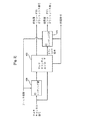
図2は、本発明の一実施例による符号化装置の構成を示すブロック図で、同図の符号化装置は、3Dレンダリング部400、420及びマルチチャンネルエンコーダ410を含んでなる。図2に示す符号化装置の動作説明において、図1を参照して説明した符号化装置の動作と重複する説明は省略する。
FIG. 2 is a block diagram showing a configuration of an encoding apparatus according to an embodiment of the present invention. The encoding apparatus of the figure includes
図2を参照すると、3Dレンダリング部400,420は、マルチチャンネルエンコーダ410の前段または後段に位置することができる。すなわち、マルチチャンネル信号は、3Dレンダリング部400で3Dレンダリングされた後、マルチチャンネルエンコーダ410に入力され、前処理エンコーダ3Dダウンミックス信号に符号化されることができ、あるいは、マルチチャンネル信号はマルチチャンネルエンコーダ410でダウンミックスされた後、3Dレンダリング部420で3Dレンダリングされ、後処理エンコーダダウンミックス信号に符号化されても良い。
Referring to FIG. 2, the
この3Dレンダリングがマルチチャンネルエンコーダ410によるダウンミックスの以前に行われたか以降に行われたかに関する情報は、符号化装置から転送されるビットストリームに含まれることが好ましい。
Information regarding whether this 3D rendering was performed before or after the downmix by the
図2では、3Dレンダリング部400,420がマルチチャンネルエンコーダ410の前段及び後段ともに位置しているが、マルチチャンネルエンコーダ410の前段及び後段のいずれか一方に3Dレンダリング部が位置することが好ましい。
In FIG. 2, the
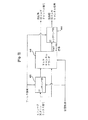
図3は、本発明の一実施例による復号化装置の構成を示すブロック図で、同図の復号化装置は、3Dレンダリング部430,450及びマルチチャンネルデコーダ440を含んでなる。図3に示す復号化装置の動作説明において、図1を参照して説明した復号化装置の動作と重複する説明は省略するものとする。
FIG. 3 is a block diagram showing a configuration of a decoding apparatus according to an embodiment of the present invention. The decoding apparatus of the figure includes
図3を参照すると、3Dレンダリング部430,450は、マルチチャンネルデコーダ440の前段または後段に位置することができる。すなわち、エンコーダ3Dダウンミックス信号は、3Dレンダリング部430で3D効果が除去された後、マルチチャンネルデコーダ440に入力され、前処理3Dマルチチャンネル信号に復号化されることができ、あるいは、エンコーダ3Dダウンミックス信号は、マルチチャンネルデコーダ440でマルチチャンネル信号に復元された後、3Dレンダリング部450で3D効果が除去され、後処理3Dマルチチャンネル信号に復号化されることができる。
Referring to FIG. 3, the
このエンコーダ3Dダウンミックス信号を生成した符号化装置で、3Dレンダリングがダウンミックス以前に行われた場合、復号化装置では3Dレンダリングがマルチチャンネルデコーディング以後に行われるようにすることが好ましい。また、符号化装置で3Dレンダリングがダウンミックス以後に行われた場合には、復号化装置では3Dレンダリングがマルチチャンネルデコーディング以前に行われるようにすることが好ましい。
When 3D rendering is performed before downmixing in the encoding device that has generated the
上記のように、符号化装置で3Dレンダリングがダウンミックス以前に行われたか、または、以後に行われたかに関する情報は、符号化装置から転送されるビットストリームから抽出されることが好ましい。 As described above, it is preferable that information regarding whether 3D rendering is performed before or after downmixing in the encoding device is extracted from the bitstream transferred from the encoding device.
図3では、3Dレンダリング部430,450がマルチチャンネルデコーダ430の前段及び後段ともに位置しているが、マルチチャンネルデコーダ430の前段及び後段のいずれか一方に3Dレンダリング部が位置することが好ましい。
In FIG. 3, the
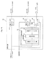
図4は、本発明の他の実施例による符号化装置の構成を示すブロック図である。同図の符号化装置は、マルチチャンネルエンコーダ500、3Dレンダリング部510、ダウンミックスエンコーダ520及びビットパッキング部530を含んでなる。図4に示す符号化装置の動作説明において、図1を参照して説明した符号化装置の動作と重複する説明は省略する。
FIG. 4 is a block diagram showing a configuration of an encoding apparatus according to another embodiment of the present invention. The encoding apparatus shown in the figure includes a
図4を参照すると、マルチチャンネルエンコーダ500は、入力されるマルチチャンネル信号を用いてダウンミックス信号と空間情報を生成し、3Dレンダリング部510は、生成されたダウンミックス信号に3Dレンダリングを行い、3Dダウンミックス信号を生成する。
Referring to FIG. 4, a
符号化装置で、ダウンミックス信号への3Dレンダリングを行うか否かは、使用者の選択、符号化/復号化装置の性能、再生環境または要求される音質などによって決定されることができる。 Whether or not to perform 3D rendering on the downmix signal in the encoding device can be determined according to user selection, performance of the encoding / decoding device, reproduction environment, or required sound quality.
ダウンミックスエンコーダ520は、マルチチャンネルエンコーダ500で生成されたダウンミックス信号または3Dレンダリング部510で生成された3Dダウンミックス信号を符号化する。
The
ビットパッキング部530は、符号化されたダウンミックス信号または符号化されたエンコーダ3Dダウンミックス信号と空間情報を用いて、ビットストリームを生成する。このビットストリームは、含まれた信号が3D効果を有しないダウンミックス信号か3D効果を有するエンコーダ3Dダウンミックス信号かを示すダウンミックス識別情報を含むことが好ましい。すなわち、ダウンミックス識別情報は、ビットストリームにダウンミックス信号が含まれているか、エンコーダ3Dダウンミックス信号が含まれているか、または、これら両信号を含んでいるかに関する情報を有することができる。
The
図5は、本発明の他の実施例による復号化装置の構成を示すブロック図であり、同図の復号化装置は、ビットアンパッキング部540、ダウンミックスデコーダ550及び3Dレンダリング部560を含んでなる。図5に示す復号化装置の動作説明において、図1を参照して説明した復号化装置の動作と重複する説明は省略する。
FIG. 5 is a block diagram illustrating a configuration of a decoding apparatus according to another embodiment of the present invention, and the decoding apparatus includes a
図5を参照すると、ビットアンパッキング部540は、入力されるビットストリームから、符号化されたダウンミックス信号、空間情報及びダウンミックス識別情報を抽出する。この抽出されたダウンミックス識別情報から、当該ビットストリームに含まれたダウンミックス信号が3D効果を有しないダウンミックス信号か、3D効果を有する3Dダウンミックス信号かがわかる。
Referring to FIG. 5, the
このビットストリームにダウンミックス信号と3Dダウンミックス信号がいずれも含まれた場合、使用者の選択、符号化/復号化装置の性能、再生環境または要求される音質などによって、これら両信号のうちいずれか一方のみが当該ビットストリームから抽出され、復号化に用いられることができる。 If this bitstream contains both a downmix signal and a 3D downmix signal, depending on the user's choice, the performance of the encoding / decoding device, the playback environment or the required sound quality, etc. Only one of them can be extracted from the bitstream and used for decoding.
ダウンミックスデコーダ550は、当該符号化されたダウンミックス信号を復号化する。この復号化された信号が、符号化装置で3Dレンダリングされたエンコーダ3Dダウンミックス信号である場合、復号化されたエンコーダ3Dダウンミックス信号は直ちに再生可能である。
The
また、復号化された信号が3D効果を有しないダウンミックス信号である場合、3Dレンダリング部560は、当該ダウンミックス信号に3Dレンダリングを行い、デコーダ3Dダウンミックス信号を生成することができる。
In addition, when the decoded signal is a downmix signal that does not have a 3D effect, the
図6は、本発明のさらに他の実施例による復号化装置の構成を示すブロック図であり、同図の復号化装置は、ビットアンパッキング部600、ダウンミックスデコーダ610、第1の3Dレンダリング部620、第2の3Dレンダリング部630及びフィルタ情報保存部640を含んでなる。図6に示す復号化装置の動作説明において、図1を参照して説明した復号化装置の動作と重複する説明は省略する。
FIG. 6 is a block diagram showing a configuration of a decoding apparatus according to another embodiment of the present invention. The decoding apparatus of the figure includes a
ビットアンパッキング部600は、入力されるビットストリームから、符号化されたエンコーダ3Dダウンミックス信号及び空間情報を抽出し、ダウンミックスデコーダ610は、当該符号化されたエンコーダ3Dダウンミックス信号を復号化する。
The
第1の3Dレンダリング部620は、符号化装置で3Dレンダリングに使用されたフィルタの逆変換フィルタを用いて、前記復号化されたエンコーダ3Dダウンミックス信号から3D効果を除去する。第2の3Dレンダリング部630は、復号化装置が持つフィルタを用いて、該3D効果の除去された信号に3Dレンダリングを行い、3D効果を有するコンバインド3Dダウンミックス信号を生成する。
The first
第2の3Dレンダリング部630は、符号化装置で3Dレンダリングに使用されたフィルタと異なる特性を有するフィルタ、例えば、符号化装置で使用されたHRTFと異なる係数を有するHRTFを用いて、3Dレンダリングを行うことが好ましい。
The second
フィルタ情報保存部640は、3Dレンダリングに用いられるフィルタに関する情報、例えば、HRTF係数情報を保存しており、第2の3Dレンダリング部630は、フィルタ情報保存部640に保存されたフィルタ情報を用いてコンバインド3Dダウンミックス信号を生成できる。
The filter
フィルタ情報保存部640は、複数のフィルタに関する情報を保存することができ、この場合、使用者の選択、装置の能力または要求される音質などによって、保存された複数のフィルタに関する情報の中からいずれか一つのフィルタ情報が選択されることができる。
The filter
人種などによって耳の構造が異なることができるので、個々人に最適化したHRTF係数は異なってくる。したがって、図6に示すような構造を有する復号化装置は、使用者が最適化した3Dダウンミックス信号を再生できるようにし、3Dダウンミックス信号の供給者が使用するHRTFによらず、使用者の希望するHRTFフィルタによる3D効果を有する3Dダウンミックス信号を再生可能である。 Since the structure of the ear can be different depending on the race or the like, the HRTF coefficient optimized for each individual differs. Therefore, the decoding apparatus having the structure as shown in FIG. 6 can reproduce the 3D downmix signal optimized by the user, regardless of the HRTF used by the supplier of the 3D downmix signal. A 3D downmix signal having a 3D effect by a desired HRTF filter can be reproduced.
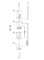
図7は、3Dレンダリングを行う3Dレンダリング部の一実施例を示す構成ブロック図であり、同図に示すように、特定ドメインで3Dレンダリングを行うためにドメイン変換部700,720が3Dレンダリング部710の前段または後段に含まれることが好ましい。
FIG. 7 is a configuration block diagram showing an embodiment of a 3D rendering unit that performs 3D rendering. As shown in FIG. 7, the
図7を参照すると、ダウンミックス信号は、第1のドメイン変換部700により周波数ドメイン上の信号に変換される。第1のドメイン変換部700は、ダウンミックス信号に離散フーリエ変換(Discrete Fourier Transform:DFT)を行ってDFTドメインに変換したり、ファーストフーリエ変換(Fast Fourier Transform:FFT)を行ってFFTドメインに変換することができる。
Referring to FIG. 7, the downmix signal is converted into a signal on the frequency domain by the
3Dレンダリング部710は、周波数ドメイン上で前記ダウンミックス信号に空間情報を適用してマルチチャンネル信号を生成し、この生成されたマルチチャンネル信号をフィルタリングして3Dダウンミックス信号を生成する。
The
この生成された3Dダウンミックス信号は、第2のドメイン変換部720により時間ドメイン信号に変換される。第2のドメイン変換部720は、前記3Dダウンミックス信号に逆離散フーリエ変換(Inverse Discrete Fourier Transform:IDFT)または逆ファーストフーリエ変換(Inverse Fast Fourier Transform:IFFT)を行うことができる。
The generated 3D downmix signal is converted into a time domain signal by the
上記のように周波数ドメイン上で生成された3Dダウンミックス信号を時間ドメイン上の信号に変換するときに、エイリアシング(aliasing)のようなデータの損失または歪曲が生じることがある。 When the 3D downmix signal generated on the frequency domain as described above is converted into a signal on the time domain, data loss or distortion such as aliasing may occur.
マルチチャンネル信号及び3Dダウンミックス信号の生成作業が周波数ドメイン上で行われるべく、パラメータバンド別に表現される空間情報は周波数ドメイン上にマッピングされ、フィルタ係数は周波数ドメイン上に変換される。 In order to perform generation of a multi-channel signal and a 3D downmix signal on the frequency domain, spatial information expressed by parameter bands is mapped on the frequency domain, and filter coefficients are converted on the frequency domain.
3Dレンダリング部710は、周波数ドメイン上でダウンミックス信号、空間情報及びフィルタ係数をかけ、3Dダウンミックス信号を生成できる。
The
M−ポイント(M−point)を有する周波数ドメイン上で表現されるダウンミックス信号、空間情報及びフィルタ係数をかけた後に時間ドメイン上の信号に変換すると、この変換された信号は、M個の有効信号を有するようになる。このようにダウンミックス信号、空間情報及びフィルタ係数をM−ポイントを有する周波数ドメイン上で表現すべく、M−ポイントDFTまたはM−ポイントFFTを使用することができる。 When converted to a signal on the time domain after applying a downmix signal represented on the frequency domain having M-points, spatial information and filter coefficients, the converted signal becomes M effective Have a signal. In this way, M-point DFT or M-point FFT can be used to represent the downmix signal, spatial information, and filter coefficients on the frequency domain having M-points.
有効信号は、複数の信号のうち、常に‘0’の値を有する信号以外の信号の個数を意味するもので、例えば、オーディオ信号をx個の信号にサンプリングをし、x個の有効信号を生成することができる。また、これらx個の有効信号のうち、y個の有効信号をゼロパッディング(zero−padding)すると、有効信号の個数が(x−y)個に減少し、a個の有効信号を有する信号とb個の有効信号を有する信号を畳み込み(convolution)すれば、(a+b−1)個の有効信号を有する信号が生成される。 The effective signal means the number of signals other than a signal always having a value of “0” among a plurality of signals. For example, an audio signal is sampled into x signals, and x effective signals are obtained. Can be generated. In addition, when y effective signals among these x effective signals are zero-padded, the number of effective signals is reduced to (xy), and a signal having a effective signals. And a signal having b effective signals are convolved to generate a signal having (a + b−1) effective signals.
このダウンミックス信号、空間情報及びフィルタ係数を周波数ドメイン上でかける過程は、時間ドメイン上で畳み込み(convolution)をする効果を奏する。前記M−ポイントを有する周波数ドメイン上で表現されるダウンミックス信号、空間情報及びフィルタ係数を、時間ドメイン上に変換したのち畳み込みをして信号を生成すると、この信号は(3*M−2)個の有効信号を有することになる。 The process of applying the downmix signal, the spatial information, and the filter coefficient on the frequency domain has an effect of convolution on the time domain. When a signal is generated by performing convolution after converting the downmix signal, spatial information, and filter coefficients expressed on the frequency domain having M-points onto the time domain, this signal is (3 * M-2). There will be valid signals.
したがって、ダウンミックス信号、空間情報及びフィルタ係数を周波数ドメイン上でかけたのち時間ドメイン上に変換して得られる信号の有効信号個数と、時間ドメイン上でダウンミックス信号、空間情報及びフィルタ係数を畳み込みして得られる信号の有効信号個数とが異なることができ、これにより、周波数ドメイン上で生成された3Dダウンミックス信号を時間ドメイン上の信号に変換するときに、エイリアシングが起きるわけである。 Therefore, the number of effective signals obtained by multiplying the downmix signal, spatial information, and filter coefficients on the frequency domain and then transforming them on the time domain is convolved with the downmix signal, spatial information, and filter coefficients on the time domain. Thus, the number of effective signals obtained can be different, and aliasing occurs when a 3D downmix signal generated on the frequency domain is converted into a signal on the time domain.
エイリアシングを防止するためには、時間ドメイン上でダウンミックス信号の有効信号個数、周波数ドメイン上にマッピングされた空間情報の有効信号個数及びフィルタの係数の個数の和が、上記Mより大きくならなければならない。周波数ドメイン上にマッピングされた空間情報の有効信号個数は、周波数ドメインのポイントにより決定される。すなわち、パラメータバンド別に表現される空間情報がN−ポイントを有する周波数ドメイン上にマッピングされる場合、このマッピングされた空間情報の有効信号個数はNとなる。 In order to prevent aliasing, the sum of the number of effective signals of the downmix signal on the time domain, the number of effective signals of the spatial information mapped on the frequency domain, and the number of filter coefficients must be larger than the above M. Don't be. The number of effective signals of spatial information mapped on the frequency domain is determined by the frequency domain points. That is, when the spatial information expressed for each parameter band is mapped on the frequency domain having N-points, the number of effective signals of the mapped spatial information is N.
図7に示すように、第1のドメイン変換部700は、第1のゼロパッディング部701及び第1の周波数ドメイン変換部702を含み、3Dレンダリング部710は、マッピング部711、時間ドメイン変換部712、第2のゼロパッディング部713、第2の周波数ドメイン変換部714、マルチチャンネル信号生成部715、第3のゼロパッディング部716、第3の周波数ドメイン変換部717及び3Dダウンミックス信号生成部718を含むことができる。
As shown in FIG. 7, the first
第1のゼロパッディング部701は、時間ドメイン上でX個サンプルを有するダウンミックス信号にゼロパッディングを行い、サンプルの個数をM個まで増加させ、第1の周波数ドメイン変換部702は、当該ゼロパッディングされたダウンミックス信号を、M−ポイントを有する周波数ドメイン上の信号に変換する。前記ゼロパッディングされたダウンミックス信号のサンプル個数はMであるが、そのうち、有効信号の個数はXである。
The first zero
マッピング部711は、パラメータバンド別に表現された空間情報をN−ポイントを有する周波数ドメイン上にマッピングさせ、時間ドメイン変換部712は、前記周波数ドメイン上にマッピングされた空間情報を、時間ドメイン上に変換する。この時間ドメイン上に変換された空間情報のサンプル個数はNである。
The
第2のゼロパッディング部713は、時間ドメイン上でN個サンプルを有する前記空間情報にゼロパッディングを行い、サンプルの個数をM個まで増加させ、第2の周波数ドメイン変換部714は、前記ゼロパッディングされた空間情報をM−ポインドを有する周波数ドメイン上の信号に変換する。前記ゼロパッディングされた空間情報のサンプル個数はMであるが、そのうち、有効信号の個数はNである。
The second zero padding unit 713 performs zero padding on the spatial information having N samples on the time domain to increase the number of samples to M, and the second frequency
マルチチャンネル信号生成部715は、M−ポイントを有する周波数ドメイン上で表現された前記ダウンミックス信号と空間情報とをかけてマルチチャンネル信号を生成する。このような周波数ドメイン上の積により生成されたマルチチャンネル信号の有効信号の個数はMであり、このような有効信号を有するダウンミックス信号と空間情報との時間ドメイン上での畳み込みにより生成されるマルチチャンネル信号の有効信号個数は(X+N−1)となる。
The multi-channel
第3のゼロパッディング部716は、時間ドメイン上で表現されるY個のフィルタ係数にゼロパッディングを行い、サンプルの個数をM個まで増加させ、第3の周波数ドメイン変換部717は、前記ゼロパッディングされたフィルタ係数を、M−ポイントを有する周波数ドメイン上の信号に変換する。前記ゼロパッディングされたフィルタ係数のサンプル個数はMであるが、そのうち、有効信号の個数はYである。
The third zero
3Dダウンミックス信号生成部718は、前記生成されたマルチチャンネル信号と前記M−ポイントを有する周波数ドメイン上に変換されたフィルタ係数とをかけ、3Dダウンミックス信号を生成する。このような周波数ドメイン上の積により生成された3Dダウンミックス信号の有効信号の個数はMであり、このような有効信号を有するマルチチャンネル信号とフィルタ係数の時間ドメイン上における畳み込みにより生成される3Dダウンミックス信号の有効信号個数は、(X+N+Y−2)となる。
The 3D downmix
第1、2、3の周波数ドメイン変換部712で変換される周波数ドメインのポイントMが、上記(X+N+Y−2)以上になるようにすることによって、エイリアシングを防止できる。すなわち、第1、2、3の周波数ドメイン変換部712が(X+N+Y−2)以上であるM−ポイントDFTまたはM−ポイントFFTを用いてドメイン変換を行うようにすることによって、エイリアシングを防止できる。
Aliasing can be prevented by making the frequency domain point M transformed by the first, second, and third frequency
周波数ドメインへの変換にはDFT、FFTだけでなく、QMF(Quadrature Mirror Filter)以外のフィルタバンクも用いられることができ、上記3Dダウンミックス信号生成にHRTFフィルタが用いられることができる。 In addition to DFT and FFT, filter banks other than QMF (Quadrature Mirror Filter) can be used for conversion to the frequency domain, and HRTF filters can be used for the 3D downmix signal generation.
上記空間情報の有効信号個数を調整する方法には、上記した方法の他の調整方法も使用可能であり、これら調整方法のうち、効率的で且つ演算量の少ない方法を選択して使用すると良い。 As the method for adjusting the number of effective signals of the spatial information, other adjustment methods described above can be used. Of these adjustment methods, a method that is efficient and has a small amount of calculation may be selected and used. .
エイリアシングは、周波数ドメインと時間ドメイン間の変換過程の他、QMF/ハイブリッドドメインへの変換過程でも発生でき、上記のようなエイリアシング防止方法は、QMF/ハイブリッドドメインへの変換過程で発生するエイリアシングにも適用可能である。 Aliasing can occur not only in the conversion process between the frequency domain and the time domain, but also in the conversion process to the QMF / hybrid domain, and the anti-aliasing method as described above also applies to the aliasing generated in the conversion process to the QMF / hybrid domain. Applicable.
また、マルチチャンネル信号の生成または3Dダウンミックス信号の生成に用いられる空間情報が変化することによって、この空間情報の変化区間で信号の不連続(discontinuity)が発生し、このような不連続は、出力信号(output signal)にノイズの形態で現れる。 In addition, when the spatial information used for generating the multi-channel signal or the 3D downmix signal is changed, a signal discontinuity is generated in the change section of the spatial information. It appears in the form of noise in the output signal.
このようなノイズは、変化区間で空間情報が急に変化しないようにするスムージング(smoothing)方法を適用することによって減少させることができる。 Such noise can be reduced by applying a smoothing method that prevents the spatial information from changing suddenly in the change interval.
例えば、隣り合う第1のフレーム(frame)と第2のフレームにそれぞれ適用される第1の空間情報と第2の空間情報が異なることから、フレーム間の不連続が発生する。 For example, discontinuity between frames occurs because the first spatial information and the second spatial information applied to the adjacent first frame and second frame are different.
この場合、第1の空間情報を第2の空間情報を用いて補正したり、第2の空間情報を第1の空間情報を用いて補正し、前記第1及び第2の空間情報間の差を減らすことによって、不連続により発生するノイズを減少させることができる。具体的には、第1及び第2の空間情報のうち少なくとも一つを、第1及び第2の空間情報の平均に取り換えてノイズを減少させることができる。 In this case, the first spatial information is corrected using the second spatial information, or the second spatial information is corrected using the first spatial information, and the difference between the first and second spatial information is determined. By reducing, noise generated by discontinuity can be reduced. Specifically, it is possible to reduce noise by replacing at least one of the first and second spatial information with the average of the first and second spatial information.
また、空間情報が対応するパラメータバンド(parameter band)のうち、隣接する2つのバンド間の不連続によってもノイズが発生する。すなわち、隣り合う第1のパラメータバンドと第2のパラメータバンドにそれぞれ対応する第3の空間情報と第4の空間情報が異なることから、パラメータバンド間の不連続が発生する。 In addition, noise is generated due to discontinuity between two adjacent bands among the parameter bands corresponding to the spatial information. That is, the third spatial information and the fourth spatial information respectively corresponding to the first parameter band and the second parameter band that are adjacent to each other are different, and thus discontinuity occurs between the parameter bands.
この場合、第3の空間情報を第4の空間情報を用いて補正したり、第4の空間情報を第3の空間情報を用いて補正し、第3及び第4の空間情報間の差を縮めることによって不連続により発生するノイズを減少させることができる。具体的には、第3及び第4の空間情報のうち少なくとも一つを、第3及び第4の空間情報の平均に取り換えてノイズを減少させることができる。 In this case, the third spatial information is corrected using the fourth spatial information, or the fourth spatial information is corrected using the third spatial information, and the difference between the third and fourth spatial information is calculated. By reducing the size, noise generated by discontinuity can be reduced. Specifically, noise can be reduced by replacing at least one of the third and fourth spatial information with the average of the third and fourth spatial information.
隣接するフレーム間またはパラメータバンド間の不連続により発生するノイズは、上記した方法の他、下記のような方法によっても減少させることができる。 Noise generated by discontinuity between adjacent frames or parameter bands can be reduced by the following method in addition to the above method.
ハニングウィンド(Hanning window)のようなウィンドを各フレームにかけ、オーバーラップ・アンド・アッド(overlap and add)の形態で進行し、フレーム間の急な変化を減らす方法を用いても良く、または、相互に異なる空間情報が適用された出力信号にスムージングを行い、該出力信号のフレーム間に急な変化が起きないように調整する方法を用いても良い。 A method such as a Hanning window can be applied to each frame and proceed in an overlap and add manner to reduce sudden changes between frames, or use mutual Alternatively, a method may be used in which smoothing is performed on an output signal to which different spatial information is applied, and adjustment is performed so as not to cause a sudden change between frames of the output signal.
DFTドメイン上で空間情報、例えば、ICCを用いてチャンネル間の無相関(decorrelation)を調整する一方法について説明すると下記の通りである。 A method of adjusting the correlation between channels using spatial information, for example, ICC, on the DFT domain will be described as follows.
OTTまたはTTTボックスの特定バンドに適用されるICC値がAである場合、このボックスに入力される信号の係数に(A+(1−A*A)^0.5*i)をかけ、無相関を調整することができる。この時、虚数部分は正と負の値から選択されることができる。 When the ICC value applied to a specific band of the OTT or TTT box is A, the coefficient of the signal input to this box is multiplied by (A + (1-A * A) ^ 0.5 * i), and uncorrelated Can be adjusted. At this time, the imaginary part can be selected from positive and negative values.
上記係数にかけられる値は、信号の特性、例えば、信号のエネルギーレベル、信号の周波数別エネルギー特性またはICC値の適用されるボックスによって適切な加重値(weighting factor)を有することができ、これにより無相関効果を調整することができ、フレーム間のスムージングや補間(interpolation)などを適用できる。 The value multiplied by the coefficient can have an appropriate weighting factor depending on the characteristics of the signal, e.g., the energy level of the signal, the frequency energy characteristics of the signal, or the box to which the ICC value is applied. The correlation effect can be adjusted, and smoothing, interpolation, etc. between frames can be applied.
図7を参照して説明したように、周波数ドメイン上で3Dダウンミックス信号を生成するために、HRTFまたは周波数ドメインに変換されたHRIR(Head Related Impulse Response)が用いられることができる。 As described with reference to FIG. 7, HRTF or HRIR (Head Related Impulse Response) converted to the frequency domain can be used to generate a 3D downmix signal on the frequency domain.
これと違い、時間ドメイン上でHRIR及びダウンミックス信号を畳み込みすることによって3Dダウンミックス信号を生成でき、周波数ドメイン上で生成された3Dダウンミックス信号に逆ドメイン変換を行わずに周波数ドメイン上に残しておいても良い。 Unlike this, the 3D downmix signal can be generated by convolving the HRIR and the downmix signal on the time domain, and the 3D downmix signal generated on the frequency domain is left on the frequency domain without performing inverse domain transformation. You can keep it.
このような時間ドメイン上での畳み込みのために、FIR(Finite Impulse Response)フィルタまたはIIR(Infinite Impulse Response)フィルタが用いられることができる。 An FIR (Finite Impulse Response) filter or an IIR (Infinite Impulse Response) filter can be used for such convolution on the time domain.
上記のように、本発明による符号化装置または復号化装置は、3Dダウンミックス信号を生成すべく、i)周波数ドメイン上でHRTFまたは周波数ドメインに変換されたHRIR(Head Related Impulse Response)を用いる方法、またはii)時間ドメイン上でHRIRを畳み込みする方法を用いることができ、これら両方法を組み合わせて使用することができる。 As described above, the encoding apparatus or decoding apparatus according to the present invention uses i) HRTF on the frequency domain or HRIR (Head Related Impulse Response) converted to the frequency domain to generate a 3D downmix signal. Or ii) The method of convolving HRIR on the time domain can be used, and both methods can be used in combination.
図8〜図11は、ビットストリーム構造の実施例を示す図である。 8 to 11 are diagrams showing an example of a bit stream structure.
図8を参照すると、ビットストリームは、マルチチャンネル信号を生成するための情報を含むマルチチャンネルデコーディング情報フィールド、3Dダウンミックス信号を生成するための情報を含む3Dレンダリング情報フィールド、及びこれらの両情報を使用するためのヘッダ情報を有するヘッダフィールドで構成されることができる。また、状況によって、これら3つのフィールドのうち一部フィールドのみを用いてビットストリームを構成しても良い。 Referring to FIG. 8, the bitstream includes a multi-channel decoding information field including information for generating a multi-channel signal, a 3D rendering information field including information for generating a 3D downmix signal, and both of these information. Can be composed of a header field having header information for using. Further, depending on the situation, a bit stream may be configured using only some of these three fields.
図9を参照すると、復号化に必要な付加情報を示すためのビットストリームは、符号化した信号全体に関するヘッダ情報を有する特定構造(specific configuration)ヘッダフィールドと、それぞれフレーム単位の付加情報を有する複数のフレームデータフィールドで構成されることができる。このフレームデータフィールドは、フレーム単位のヘッダ情報を有するフレームヘッダフィールドと、フレーム単位の空間情報を有するフレームパラメータデータフィールドとを含むことができる。あるいは、フレームデータフィールドは、空間情報を含むフレームパラメータデータフィールドのみで構成されても良い。 Referring to FIG. 9, a bit stream for indicating additional information necessary for decoding includes a specific configuration header field having header information about the entire encoded signal, and a plurality of pieces of additional information each having frame-based additional information. Frame data field. The frame data field may include a frame header field having header information in units of frames and a frame parameter data field having spatial information in units of frames. Alternatively, the frame data field may be composed only of a frame parameter data field including spatial information.
フレームパラメータデータフィールドは、フラグとパラメータデータとで構成されるモジュールを複数個含むことができる。このモジュールは、空間情報などのパラメータデータ及びそれから生成された信号の音質向上のためのデータ、例えば、ダウンミックスゲイン、スムージングデータの集合を意味する。 The frame parameter data field can include a plurality of modules including flags and parameter data. This module refers to a set of parameter data such as spatial information and data for improving the sound quality of a signal generated therefrom, for example, downmix gain and smoothing data.
前記フレームヘッダフィールドで指定した情報に関連したモジュールデータを別のフラグ無しで受信する場合、フレームヘッダフィールドで指定した情報をより詳細に分類する場合、またはフレームヘッダフィールドで指定しない情報に対して別のフラグと情報を受信する場合には、前記フラグが省略されても良い。 When module data related to the information specified in the frame header field is received without another flag, when the information specified in the frame header field is classified in more detail, or different from information not specified in the frame header field. If the flag and information are received, the flag may be omitted.
一方、上記の3Dダウンミックス信号と関連した付加情報、例えば、HRTF係数情報などは、特定構造ヘッダフィールド、フレームヘッダ及びフレームパラメータデータフィールドのうち少なくとも一つに含まれることができる。 Meanwhile, additional information related to the 3D downmix signal, such as HRTF coefficient information, may be included in at least one of the specific structure header field, the frame header, and the frame parameter data field.
図10を参照すると、ビットストリームは、マルチチャンネル信号を生成するための情報を含むマルチチャンネルデコーディング情報フィールド、及び3Dダウンミックス信号を生成するための情報を含む3Dレンダリング情報フィールドで構成されることができる。 Referring to FIG. 10, the bitstream includes a multi-channel decoding information field including information for generating a multi-channel signal and a 3D rendering information field including information for generating a 3D downmix signal. Can do.
このような構成を有するビットストリームを受信した復号化装置は、再生しようとする信号によって、上記2つのフィールドのいずれか一つのフィールドのみを読み込んで復号化に用い、残り一つのフィールドはスキップ(skip)することができる。 The decoding apparatus that receives the bit stream having such a configuration reads only one of the two fields according to the signal to be reproduced and uses it for decoding, and skips the remaining one field (skip). )can do.
すなわち、マルチチャンネル信号を生成しようとする場合、復号化装置は、3Dレンダリング情報フィールドをスキップし、マルチチャンネルデコーディング情報フィールドに含まれた情報のみを読み込むことができる。また、3Dダウンミックス信号を生成しようとする場合には、復号化装置は、マルチチャンネルデコーディング情報フィールドをスキップし、3Dレンダリング情報フィールドに含まれた情報のみを読み込むことができる。 That is, when generating a multi-channel signal, the decoding apparatus can skip the 3D rendering information field and read only the information included in the multi-channel decoding information field. When generating a 3D downmix signal, the decoding apparatus can skip the multi-channel decoding information field and read only the information included in the 3D rendering information field.
複数のフィールドのうち一部をスキップする方法の実施例について説明すると、下記の通りである。 An embodiment of a method for skipping a part of a plurality of fields will be described as follows.
第一、フィールドの全体ビット数に関するフィールド長情報をビットストリームに含め、このビット数に該当するデータをスキップすることによって、所望のフィールドをスキップすることができる。このフィールド長情報は、該当のフィールドの開始部分に位置することが好ましい。 First, a desired field can be skipped by including field length information relating to the total number of bits of the field in the bit stream and skipping data corresponding to the number of bits. This field length information is preferably located at the start of the corresponding field.
第二、フィールドの終了部分または開始部分にシンクワード(syncword)を配置し、このシンクワードを用いてフィールドの位置を把握することによって、所望のフィールドをスキップすることができる。 Second, by placing a sync word at the end or start of the field and grasping the position of the field using this sync word, a desired field can be skipped.
第三、フィールド長があらかじめ定められ固定されている場合には、この固定された長さに該当するデータ分だけスキップすることによって所望のフィールドをスキップすることができる。このフィールドの固定長さ情報は、ビットストリームに含まれたり、復号化装置に保存されていることができる。 Third, when the field length is predetermined and fixed, a desired field can be skipped by skipping data corresponding to the fixed length. The fixed length information of this field can be included in the bitstream or stored in the decoding device.
第四、上記のような3つのフィールドスキップ方法のうち、2つ以上を組み合わせて用いることによって、複数のフィールドのうち所望のフィールドをスキップすることができる。 Fourth, a desired field of a plurality of fields can be skipped by combining two or more of the three field skip methods as described above.
上記スキップ情報、例えば、フィールド長情報、シンクワードまたは固定長さ情報は、図9に示す特定構造ヘッダフィールド、フレームヘッダフィールド及びフレームパラメータデータフィールドのうち、少なくともいずれか一つに含まれたり、これら3つのフィールド以外の新しく定義されるフィールドに含まれることができる。
例えば、マルチチャンネル信号を生成しようとする場合、復号化装置は、3Dレンダリング情報フィールドの開始部分に含まれたフィールド長情報、マルチチャンネルデコーディング情報フィールドの開始部分に含まれたシンクワードまたは3Dレンダリング情報フィールドの固定長さ情報を用いて、3Dレンダリング情報フィールドをスキップし、マルチチャンネルデコーディング情報フィールドに含まれた情報のみを読み込むことができる。
The skip information, for example, field length information, sync word or fixed length information is included in at least one of the specific structure header field, the frame header field, and the frame parameter data field shown in FIG. It can be included in newly defined fields other than three fields.
For example, when generating a multi-channel signal, the decoding apparatus may use field length information included in the start portion of the 3D rendering information field, sync word included in the start portion of the multi-channel decoding information field, or 3D rendering. Using the fixed length information of the information field, the 3D rendering information field can be skipped and only the information included in the multi-channel decoding information field can be read.
また、3Dダウンミックス信号を生成しようとする場合、復号化装置は、マルチチャンネルデコーディング情報フィールドの開始部分に含まれたフィールド長情報、3Dレンダリング情報フィールドの開始部分に含まれたシンクワード、またはマルチチャンネルデコーディング情報フィールドの固定長さ情報を用いて、マルチチャンネルデコーディング情報フィールドをスキップし、3Dレンダリング情報フィールドに含まれたデータのみを読み込むことができる。 When the 3D downmix signal is to be generated, the decoding apparatus may use the field length information included in the start portion of the multi-channel decoding information field, the sync word included in the start portion of the 3D rendering information field, or Using the fixed length information of the multi-channel decoding information field, the multi-channel decoding information field can be skipped and only the data included in the 3D rendering information field can be read.
ビットストリームは、含んでいるデータがマルチチャンネル信号を生成するためのものか、3Dダウンミックス信号生成のためのものかに関する情報を有することができる。 The bitstream can have information on whether the data it contains is for generating a multi-channel signal or for generating a 3D downmix signal.
一方、ビットストリームに、CLDのような空間情報は含まれず、3Dダウンミックス信号生成のためのデータ(例えば、HRTFフィルタ係数)のみ含まれる場合、空間情報無しで3Dダウンミックス信号生成のためのデータのみを用いて復号化することによって、マルチチャンネル信号を再生することができる。 On the other hand, when the bitstream does not include spatial information such as CLD and includes only data for generating a 3D downmix signal (for example, an HRTF filter coefficient), data for generating a 3D downmix signal without spatial information. By decoding using only the multi-channel signal, it is possible to reproduce the multi-channel signal.
例えば、ダウンミックス信号から2チャンネルに関する空間情報であるステレオパラメータを求めた後、このステレオパラメータを再生しようとする複数のチャンネルに関する空間情報に変換し、この変換された空間情報を前記ダウンミックス信号に適用することによってマルチチャンネル信号を生成することができる。 For example, after obtaining a stereo parameter that is spatial information about two channels from a downmix signal, the stereo parameter is converted into spatial information about a plurality of channels to be reproduced, and the converted spatial information is converted into the downmix signal. By applying, a multi-channel signal can be generated.
一方、ビットストリームにマルチチャンネル信号生成のためのデータのみ含まれた場合は、別の復号化作業無しでダウンミックス信号を再生したり、復号化装置に含まれた別のHRTFフィルタを用いて前記ダウンミックス信号に3Dプロセシングを行い、3Dダウンミックス信号を再生しても良い。 On the other hand, when only the data for generating the multi-channel signal is included in the bitstream, the downmix signal is reproduced without a separate decoding operation, or the HRTF filter included in the decoding device is used. The 3D processing may be performed on the downmix signal to reproduce the 3D downmix signal.
また、ビットストリームにマルチチャンネル信号生成のためのデータと3Dダウンミックス信号生成のためのデータが両方とも含まれた場合、使用者がこれらの信号から、再生する信号を選択するようにすることができる。 In addition, when the data for generating the multi-channel signal and the data for generating the 3D downmix signal are both included in the bitstream, the user may select a signal to be reproduced from these signals. it can.
以下では、復号化過程を示すシンタックス(syntax)に挙げて、一部のデータをスキップする方法の実施例について説明する。 Hereinafter, an example of a method for skipping a part of data will be described with reference to a syntax indicating a decoding process.
まず、フレーム単位にオーディオ信号を復号化する過程を示すシンタックスは、次の通りである。 First, the syntax indicating the process of decoding an audio signal in units of frames is as follows.

このシンタックスで、Ottdata()とTttData()は、CLD、ICC、CPCなどの空間情報のように、ダウンミックス信号をマルチチャンネル信号に復元するのに必須なパラメータを示すモジュールである。SmgData()、TempShapeData()、ArbitraryDownmixData()、ResidualData()は、符号化過程における歪曲を補正し、音質を向上させるために必要な情報を示すモジュールである。 With this syntax, Ottdata () and TttData () are modules indicating parameters essential for restoring a downmix signal to a multichannel signal, such as spatial information such as CLD, ICC, and CPC. SmgData (), TempShapeData (), ArbitraryDownmixData (), and ResidualData () are modules indicating information necessary for correcting distortion in the encoding process and improving sound quality.
例えば、復号化過程で、CLD、ICCまたはCPCのようなパラメータとArbitraryDownmixData()に含まれた情報のみを使用する場合、TttData()とArbitraryDownmixData()間に存在するSmgData()とTempShapeData()は不要になる。したがって、SmgData()モジュールとTempShapeData()モジュールはスキップすることが効率的である。 For example, when only parameters such as CLD, ICC or CPC and information included in ArbitraryDownmixData () are used in the decoding process, SmgData () and TempShapeData () existing between TttData () and ArbitraryDownmixData () are It becomes unnecessary. Therefore, it is efficient to skip the SmgData () module and the TempShapeData () module.
下記のシンタックス2は、一部モジュールをスキップする方法の第1の実施例を示す。 The following syntax 2 shows a first embodiment of a method for skipping some modules.
このシンタックスに示すように、SkipData()モジュールは、スキップしようとするモジュールの前に定義され、このSkipData()モジュールの内部に、スキップしようとするモジュールの全体ビット数(bsSkipBits)を指定する。 As shown in this syntax, the SkipData () module is defined before the module to be skipped, and the total number of bits (bsSkipBits) of the module to be skipped is specified inside this SkipData () module.
すなわち、スキップするSmgData()とTempShapeData()モジュールに用いられる全体ビット数を150ビットとすれば、SmgData()とTempShapeData()モジュールの前にSkipData()モジュールを定義し、bsSkipBitsを150ビットと指定することによって、150ビットに該当するSmgData()とTempShapeData()モジュールをスキップすることができる。 That is, if the total number of bits used for the skipped SmgData () and TempShapeData () modules is 150 bits, the SkipData () module is defined before the SmgData () and TempShapeData () modules, and bsSkipBits is specified as 150 bits. By doing so, the SmgData () and TempShapeData () modules corresponding to 150 bits can be skipped.
下記のシンタックス3は、一部モジュールをスキップする方法の第2の実施例を示す。 The following syntax 3 shows a second embodiment of a method for skipping some modules.
このシンタックスに示すように、シンクワードの使用有無に関する情報を有するbsSkipSyncflagとスキップされるモジュールの終了部分に位置するbsSkipSyncwordを用いて、余分なモジュールをスキップすることができる。 As shown in this syntax, an extra module can be skipped by using bsSkipSyncflag having information on whether or not a sync word is used and bsSkipSyncword located at the end of the skipped module.
すなわち、bsSkipSyncflagをシンクワードを使用するものと指定すれば、このフラグ以下のモジュールは、シンクワードが現れるまでスキップされる。したがって、このシンタックス3では、bsSkipSyncflagとbsSkipSyncword間のSmgData()及びTempShapeData()モジュールがスキップされることができる。 That is, if bsSkipSyncflag is specified to use a sync word, modules below this flag are skipped until a sync word appears. Therefore, with this syntax 3, the SmgData () and TempShapeData () modules between bsSkipSyncflag and bsSkipSyncword can be skipped.
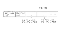
図11を参照すると、ビットストリームは、マルチチャンネル信号の再生のためのヘッダ情報を有するマルチチャンネルヘッダフィールド、3Dダウンミックス信号の再生のためのヘッダ情報を有する3Dレンダリングヘッダフィールド、及びそれぞれマルチチャンネル信号の再生のためのデータを有する複数のマルチチャンネルデコーディング情報フィールドを含む。 Referring to FIG. 11, the bitstream includes a multi-channel header field having header information for reproducing a multi-channel signal, a 3D rendering header field having header information for reproducing a 3D downmix signal, and a multi-channel signal, respectively. A plurality of multi-channel decoding information fields having data for reproduction of the same.
マルチチャンネル信号を再生しようとする場合、復号化装置は、3Dレンダリングヘッダフィールドをスキップし、マルチチャンネルヘッダフィールドに含まれたヘッダ情報とマルチチャンネルデコーディング情報フィールドに含まれたデータを読み込み、マルチチャンネル信号を生成する。 When attempting to reproduce a multi-channel signal, the decoding apparatus skips the 3D rendering header field, reads the header information included in the multi-channel header field and the data included in the multi-channel decoding information field, Generate a signal.
この3Dレンダリングヘッダフィールドをスキップする方法の実施例は、図10を参照して説明したフィールドスキップ方法と同一なので、その説明は省略する。 Since the embodiment of the method for skipping the 3D rendering header field is the same as the field skip method described with reference to FIG. 10, the description thereof is omitted.
3Dダウンミックス信号を再生しようとする場合、復号化装置は、マルチチャンネルデコーディング情報フィールドに含まれたデータと3Dレンダリングヘッダフィールドに含まれたヘッダ情報を用いて3Dダウンミックス信号を生成できる。例えば、復号化装置は、マルチチャンネルデコーディング情報フィールドに含まれたダウンミックス信号と3Dレンダリングヘッダフィールドに含まれたHRTF係数情報を用いて3Dダウンミックス信号を生成することができる。 When trying to reproduce the 3D downmix signal, the decoding apparatus can generate the 3D downmix signal using the data included in the multi-channel decoding information field and the header information included in the 3D rendering header field. For example, the decoding apparatus may generate a 3D downmix signal using the downmix signal included in the multi-channel decoding information field and the HRTF coefficient information included in the 3D rendering header field.
図12は、本発明の一実施例による任意ダウンミックス信号を処理する符号化/復号化装置の構成を示すブロック図であり、任意ダウンミックス信号は、符号化器800に含まれたマルチチャンネルエンコーダ801により生成されたダウンミックス信号でないダウンミックス信号を意味する。図12に示す符号化/復号化装置の動作説明において、図1を参照して説明した符号化/復号化装置の動作と重複する説明は省略する。
FIG. 12 is a block diagram illustrating a configuration of an encoding / decoding apparatus that processes an arbitrary downmix signal according to an embodiment of the present invention. The arbitrary downmix signal is a multi-channel encoder included in the
図12を参照すると、符号化器800は、マルチチャンネルエンコーダ801、空間情報合成部802及び比較部803を含んでなる。
Referring to FIG. 12, the
マルチチャンネルエンコーダ801は、マルチチャンネル信号をステレオまたはモノラルのダウンミックス信号にダウンミックスし、このダウンミックス信号からマルチチャンネル信号を復元するのに必要な空間情報を生成する。 The multichannel encoder 801 downmixes the multichannel signal into a stereo or monaural downmix signal, and generates spatial information necessary to restore the multichannel signal from the downmix signal.
比較部803は、前記生成されたダウンミックス信号と任意ダウンミックス信号とを比較し、任意ダウンミックス信号を補償し、前記ダウンミックス信号に近似する信号に変換するための補償情報を生成する。復号化装置は、前記補償情報を用いて任意ダウンミックス信号を補償した後、この補償された任意ダウンミックス信号を用いてマルチチャンネル信号を生成することによって、原本信号により近似するマルチチャンネル信号を復元することができる。 The comparison unit 803 compares the generated downmix signal with the arbitrary downmix signal, compensates the arbitrary downmix signal, and generates compensation information for conversion to a signal approximate to the downmix signal. The decoding apparatus compensates the arbitrary downmix signal using the compensation information, and then generates a multichannel signal using the compensated arbitrary downmix signal, thereby restoring the multichannel signal approximated to the original signal. can do.
ここで、補償情報は、マルチチャンネルエンコーダ801で生成されたダウンミックス信号と任意ダウンミックス信号との差分に関する情報を意味することができる。復号化装置は、任意ダウンミックス信号に、前記差分情報(difference information)に相応する信号を加え、任意ダウンミックス信号を補償することができる。 Here, the compensation information may mean information regarding a difference between the downmix signal generated by the multi-channel encoder 801 and the arbitrary downmix signal. The decoding apparatus can compensate the arbitrary downmix signal by adding a signal corresponding to the difference information to the arbitrary downmix signal.
また、差分情報は、ダウンミックス信号と任意ダウンミックス信号間のエネルギーレベル差に関する情報であるダウンミックスゲインでありうる。 Further, the difference information may be a downmix gain that is information related to an energy level difference between the downmix signal and the arbitrary downmix signal.
このダウンミックスゲインは、周波数バンド別に求められても良く、時間あるいは時間スロット(time slot)別に求められても良く、チャンネル別に求められても良い。これら3つの方法を組み合わせて求めても良い。例えば、一部のダウンミックスゲインは、周波数バンド別に求められ、他の一部のダウンミックスゲインは、時間スロット別に求められても良い。 The downmix gain may be obtained for each frequency band, may be obtained for each time or time slot, and may be obtained for each channel. You may obtain | require combining these three methods. For example, some downmix gains may be obtained for each frequency band, and some other downmix gains may be obtained for each time slot.
また、前記ダウンミックスゲインは、パラメータバンド別に求められるか、任意ダウンミックス信号に最適化された周波数帯域別に求められても良い。このパラメータバンドは、パラメータ形態の空間情報が適用される周波数間隔のことをいう。 The downmix gain may be obtained for each parameter band or for each frequency band optimized for an arbitrary downmix signal. The parameter band refers to a frequency interval to which spatial information in a parameter form is applied.
求められたダウンミックス信号と任意ダウンミックス信号とのエネルギーレベル差は量子化されても良い。求められたエネルギーレベル差を量子化するための量子化レベルの分解能は、CLD(Channel Level Difference)の量子化レベル分解能と等しい、または、異なることができる。また、上記2つのダウンミックス信号間のエネルギーレベル差の量子化レベルは、CLDの量子化レベルの一部または全部を使用したり、CLDの量子化レベルの一部または全部と新しく定義された量子化レベルを組み合わせて使用することができる。 The obtained energy level difference between the downmix signal and the arbitrary downmix signal may be quantized. The resolution of the quantization level for quantizing the obtained energy level difference may be equal to or different from the quantization level resolution of CLD (Channel Level Difference). The quantization level of the energy level difference between the two downmix signals may be a part or all of the CLD quantization level or a newly defined quantum level of part or all of the CLD quantization level. Can be used in combination.
2つのダウンミックス信号間エネルギーレベル差の分解能は、CLDの分解能より平均的に小さいので、求められたエネルギーレベル差を量子化するための量子化レベルの分解能は、CLDの量子化レベル分解能より細密な値を有するようにすることができる。 Since the resolution of the energy level difference between the two downmix signals is on average smaller than the resolution of the CLD, the quantization level resolution for quantizing the obtained energy level difference is finer than the quantization level resolution of the CLD. Can have different values.
任意ダウンミックス信号を補償するための補償情報は、マルチチャンネル信号のうち、任意ダウンミックス信号またはダウンミックスゲインを用いて復元されない成分に関するレジデュアル情報を含む拡張情報でありうる。復号化装置は、任意ダウンミックス信号またはダウンミックスゲインを用いて復元されない成分まで拡張情報を用いて復元することによって、原本信号に近いマルチチャンネル信号を復元することができる。 The compensation information for compensating the arbitrary downmix signal may be extended information including residual information regarding a component that is not restored using the arbitrary downmix signal or the downmix gain in the multi-channel signal. The decoding apparatus can restore a multi-channel signal close to the original signal by restoring using the extended information up to a component that is not restored using the arbitrary downmix signal or the downmix gain.
このような拡張情報を生成する方法の実施例について説明すると、下記の通りである。 An example of a method for generating such extension information will be described as follows.
マルチチャンネルエンコーダ801は、入力されるマルチチャンネル信号のうち、生成されたダウンミックス信号に含まれない成分に関する情報を、第1の拡張情報として生成することができる。復号化装置は、ダウンミックス信号と空間情報を用いてマルチチャンネル信号を生成する段階で第1の拡張情報を適用することによって、原本信号に近いマルチチャンネル信号を復元できる。 The multi-channel encoder 801 can generate information about components that are not included in the generated downmix signal among the input multi-channel signals as the first extension information. The decoding apparatus can restore the multichannel signal close to the original signal by applying the first extension information at the stage of generating the multichannel signal using the downmix signal and the spatial information.
マルチチャンネルエンコーダ801は、ダウンミックス信号と空間情報を用いてマルチチャンネル信号を復元し、この復元されたマルチチャンネル信号と原本マルチチャンネル信号間の差を求めることによって、第1の拡張情報を求めることができる。 The multi-channel encoder 801 restores the multi-channel signal using the downmix signal and the spatial information, and obtains the first extension information by obtaining the difference between the restored multi-channel signal and the original multi-channel signal. Can do.
比較部803は、マルチチャンネルエンコーダ801で生成されたダウンミックス信号のうち、任意ダウンミックス信号にない成分、すなわち、ダウンミックスゲインを用いて補償されない成分に関する情報を、第2の拡張情報として生成できる。復号化装置は、第2の拡張情報を用いて任意ダウンミックス信号をより前記ダウンミックス信号に近く補償することができる。 The comparison unit 803 can generate, as the second extension information, information related to a component that is not included in the arbitrary downmix signal, that is, a component that is not compensated using the downmix gain among the downmix signal generated by the multichannel encoder 801. . The decoding apparatus can compensate the arbitrary downmix signal closer to the downmix signal by using the second extension information.
この拡張情報は、上記した方法の他、様々なレジデュアルコーディング方法を用いて生成されることができる。 This extended information can be generated using various residual coding methods in addition to the above-described method.
ダウンミックスゲインと拡張情報が共に補償情報として用いられることができる。例えば、全体周波数帯域に対してダウンミックスゲインと拡張情報を求めたり、一部周波数帯域に対してはダウンミックスゲインを求め、残りの周波数帯域に対しては拡張情報を求め、補償情報として使用することができる。一実施例として、低周波帯域に対しては拡張情報を補償情報として用い、高周波帯域に対してはダウンミックスゲインを補償情報として用いることができる。 Both the downmix gain and the extended information can be used as compensation information. For example, the downmix gain and extension information are obtained for the entire frequency band, the downmix gain is obtained for a part of the frequency band, and the extension information is obtained for the remaining frequency band and used as compensation information. be able to. As an example, extended information can be used as compensation information for low frequency bands, and downmix gain can be used as compensation information for high frequency bands.
また、低周波帯域の他に、ピーク(peak)またはノッチ(notch)などのように音質に重要な影響を及ぼす部分も、拡張情報を補償情報として用いることが好ましい。 In addition to the low frequency band, it is also preferable to use the extended information as compensation information for portions that have a significant effect on sound quality, such as peaks or notches.
空間情報合成部802は、マルチチャンネルエンコーダ801で生成されたマルチチャンネル信号復元のための基本空間情報、例えば、CLD、CPC、ICC、CTDなどと前記補償情報を空間情報として合成する。すなわち、復号化装置で転送される空間情報は、マルチチャンネル信号復元のための基本空間情報、ダウンミックスゲイン、第1及び第2の拡張情報などを含むことができる。
The spatial
前記合成された空間情報は、任意ダウンミックス信号と一緒にビットストリームに含まれ、復号化装置に転送される。 The synthesized spatial information is included in a bitstream together with an arbitrary downmix signal and transferred to a decoding device.
前記拡張情報と任意ダウンミックス信号は、AAC、MP3またはBSACなどのエンコーダを用いて符号化されることができる。前記拡張情報及び前記任意ダウンミックス信号は、同じオーディオエンコーダを用いてエンコードされても良いし、異なるオーディオエンコーダを用いてエンコードされても良い。 The extension information and the arbitrary downmix signal may be encoded using an encoder such as AAC, MP3, or BSAC. The extension information and the arbitrary downmix signal may be encoded using the same audio encoder, or may be encoded using different audio encoders.
これら2つのオーディオエンコーダが同一である場合、復号化装置においても1種類のオーディオデコーダのみで復号化作業が可能である。この場合、任意ダウンミックス信号の復号化は常に可能な状態で始まるので、前記拡張情報を復号化できない場合は発生しない。ただし、任意ダウンミックス信号は、復号化されたPCM信号の形態で復号化装置に入力されるので、前記任意ダウンミックス信号に使用されたオーディオコーデックの種類がわからず、よって、拡張情報に使用されたオーディオコーデックの種類もわからない。 When these two audio encoders are the same, the decoding operation can be performed with only one type of audio decoder in the decoding apparatus. In this case, since the decoding of the arbitrary downmix signal always starts in a possible state, it does not occur when the extension information cannot be decoded. However, since the arbitrary downmix signal is input to the decoding device in the form of a decoded PCM signal, the type of the audio codec used for the arbitrary downmix signal is not known, and thus is used for extension information. I do not know the type of audio codec.
したがって、任意ダウンミックス信号と拡張情報の符号化に使用されたオーディオコーデックの種類に関する情報をビットストリームに挿入することが好ましい。 Therefore, it is preferable to insert information regarding the type of audio codec used for encoding the arbitrary downmix signal and extension information into the bitstream.
前記オーディオコーデック種類に関する情報は、ビットストリームのうち、特定構造ヘッダフィールドに挿入され、復号化装置は、前記ビットストリームの特定構造ヘッダフィールドから前記情報を抽出し、拡張情報の復号化に用いる。 Information on the audio codec type is inserted into a specific structure header field of the bitstream, and the decoding apparatus extracts the information from the specific structure header field of the bitstream and uses it for decoding of extended information.
上記2つのオーディオエンコーダが異なる場合、拡張情報の復号化が不可能な状況が発生することがあり、その場合、拡張情報の終点がわからないため、それ以上の復号化作業進行は不可能になる。 When the two audio encoders are different from each other, there may occur a situation in which the extension information cannot be decoded. In this case, since the end point of the extension information is not known, no further decoding work progresses.
したがって、任意ダウンミックス信号と拡張情報に使用されたオーディオコーデックの種類に関する情報を、ビットストリームのうちの特定構造ヘッダフィールドに挿入し、復号化装置は、前記ビットストリームの特定構造ヘッダフィールドから前記情報を抽出し、拡張情報の復号化に用いる。拡張情報を復号化するためのデコーダが復号化装置に存在しない場合、拡張情報の復号化作業を進行せず、その次の情報を読む過程を行う。 Therefore, the information about the type of the audio codec used for the arbitrary downmix signal and the extension information is inserted into the specific structure header field of the bitstream, and the decoding apparatus extracts the information from the specific structure header field of the bitstream. Is extracted and used to decode the extended information. When the decoder for decoding the extension information does not exist in the decoding apparatus, the decoding process of the extension information does not proceed, and the process of reading the next information is performed.
拡張情報に対して用いられるコーデックの種類に関する情報は、ビットストリームのうち、特定構造ヘッダフィールドに含まれた特定シンタックスエレメント(syntax element)を通じて表現されることができる。例えば、前記コーデック情報は、次のテーブル1に示すようなbsResidualCodecTypeという4ビットのシンタックスエレメントにより表現されることができる。 Information on the type of codec used for the extended information can be expressed through a specific syntax element included in a specific structure header field of the bitstream. For example, the codec information can be expressed by a 4-bit syntax element called bsResidualCodecType as shown in Table 1 below.
前記拡張情報は、前記レジデュアル情報と一緒にチャンネル拡張情報を含むことができる。前記チャンネル拡張情報は、空間情報により復号化されるマルチチャンネル信号よりも多い数のチャンネルを有する信号に拡張するための情報を意味し、例えば、5.1チャンネルまたは7.1チャンネル信号を、9.1チャンネル信号に拡張するための情報でありうる。 The extension information may include channel extension information together with the residual information. The channel extension information means information for extending a signal having a larger number of channels than a multi-channel signal decoded by spatial information. For example, a 5.1 channel signal or a 7.1 channel signal is Information for extending to 1 channel signal.
前記拡張情報は、ビットストリームに含まれて復号化装置に転送されることができ、復号化装置は、前記拡張情報を用いてダウンミックス信号を補償したり、マルチチャンネル信号のチャンネルを拡張させることができる。 The extension information may be included in a bitstream and transferred to a decoding device, and the decoding device may compensate for a downmix signal or extend a channel of a multi-channel signal using the extension information. Can do.
また、復号化装置は、ビットストリームに含まれた前記拡張情報を抽出せずに、スキップすることができる。例えば、ビットストリームに含まれた3Dダウンミックス信号を用いてマルチチャンネル信号を生成したり、ビットストリームに含まれたダウンミックス信号を用いて3Dダウンミックス信号を生成しようとする場合、復号化装置は、ビットストリームのうち、前記拡張情報をスキップすることが好ましい。
ビットストリームのうち、前記拡張情報をスキップする方法は、図10を参照して説明したスキップ方法と同一にすれば良い。
In addition, the decoding apparatus can skip the extended information included in the bitstream without extracting the extended information. For example, when generating a multi-channel signal using a 3D downmix signal included in a bitstream or generating a 3D downmix signal using a downmix signal included in a bitstream, the decoding apparatus may It is preferable to skip the extension information in the bitstream.
The method for skipping the extension information in the bitstream may be the same as the skip method described with reference to FIG.
例えば、拡張情報の開始部分に位置する前記拡張情報の全体ビット数に関する情報、前記拡張情報の開始部分または終了部分に位置するシンクワード、前記拡張情報の固定されたビット数に関する情報のうち少なくとも一つを用いて、ビットストリームのうち前記拡張情報部分をスキップすることができる。前記スキップのための情報は、ビットストリームに含まれていることが好ましく、前記固定ビット数情報は、復号化装置に保存されていても良い。 For example, at least one of information on the total number of bits of the extension information located at the start portion of the extension information, a sync word located at the start portion or end portion of the extension information, and information about the fixed number of bits of the extension information Can be used to skip the extension information portion of the bitstream. The information for skipping is preferably included in a bitstream, and the fixed bit number information may be stored in a decoding device.
図12を参照すると、復号化器810は、ダウンミックス補償部811、3Dレンダリング部815及びマルチチャンネルデコーダ816を含んでなる。
Referring to FIG. 12, the decoder 810 includes a
ダウンミックス補償部811は、空間情報に含まれた補償情報、例えば、ダウンミックスゲインまたは拡張情報を用いて任意ダウンミックス信号を補償する。
The
3Dレンダリング部815は、前記補償されたダウンミックス信号に3Dレンダリングを行い、デコーダ3Dダウンミックス信号を生成する。また、マルチチャンネルデコーダ816は、前記補償されたダウンミックス信号と前記空間情報に含まれた基本空間情報を用いて3Dマルチチャンネル信号を生成する。
The 3D rendering unit 815 performs 3D rendering on the compensated downmix signal to generate a
ダウンミックス補償部811が任意ダウンミックス信号を補償する方法の実施例について説明すると、下記の通りである。
An example of a method in which the
前記補償情報がダウンミックスゲインである場合、ダウンミックス補償部811は、任意ダウンミックス信号のエネルギーレベルを前記ダウンミックスゲインを用いて補償し、前記任意ダウンミックス信号をダウンミックス信号に近い信号に変換することができる。
When the compensation information is a downmix gain, the
前記補償情報が第2の拡張情報である場合、ダウンミックス補償部811は、前記第2の拡張情報を用いて前記任意ダウンミックス信号にない成分を補償できる。
When the compensation information is the second extension information, the
マルチチャンネルデコーダ816は、ダウンミックス信号にpre−matrix M1、mix−matrix M2及びpost−matrix M3を順次に適用し、マルチチャンネル信号を生成できるが、前記第1の拡張情報は、mix−matrix M2の適用段階で用いられてダウンミックス信号を補償することができる。すなわち、前記第2の拡張情報を用いてpre−matrix M1が適用された任意ダウンミックス信号を補償できる。 The multi-channel decoder 816 can generate a multi-channel signal by sequentially applying pre-matrix M1, mix-matrix M2 and post-matrix M3 to the downmix signal. The first extension information is a mix-matrix M2 Can be used to compensate the downmix signal. That is, an arbitrary downmix signal to which pre-matrix M1 is applied can be compensated using the second extension information.
上記のようにマルチチャンネル信号生成過程中に拡張情報を適用することによって、複数のチャンネルのうち特定チャンネルに対する補償が可能となる。例えば、拡張情報がmix−matrix M2のセンターチャンネルに適用される場合、ダウンミックス信号の左側及び右側チャンネル信号が前記拡張情報を用いて補償され、拡張情報がmix−matrix M2の左側チャンネルに適用される場合には、ダウンミックス信号の左側チャンネル信号が、前記拡張情報を用いて補償されるようにすることができる。 By applying the extension information during the multi-channel signal generation process as described above, it is possible to compensate for a specific channel among a plurality of channels. For example, when the extension information is applied to the center channel of mix-matrix M2, the left and right channel signals of the downmix signal are compensated using the extension information, and the extension information is applied to the left channel of mix-matrix M2. In this case, the left channel signal of the downmix signal can be compensated using the extension information.
また、前記補償情報として前記ダウンミックスゲインと拡張情報が共に用いられることができる。例えば、任意ダウンミックス信号の低周波帯域は、前記拡張情報を用いて補償され、高周波帯域は、前記ダウンミックスゲインを用いて補償されるようにすることができる。また、低周波帯域の他に、ピーク、ノッチなどのように音質に重要な影響を及ぼす部分も、前記拡張情報により補償されるようにすることができる。前記拡張情報が適用される領域に関する情報は、符号化装置から転送されるビットストリームに含まれていることが好ましい。また、前記ビットストリームは、含まれたダウンミックス信号が任意ダウンミックス信号か否かに関する情報、及び補償情報を含むか否かに関する情報を含むことができる。 Further, both the downmix gain and the extended information can be used as the compensation information. For example, a low frequency band of an arbitrary downmix signal may be compensated using the extension information, and a high frequency band may be compensated using the downmix gain. Further, in addition to the low frequency band, portions that have an important influence on sound quality such as peaks and notches can be compensated by the extended information. It is preferable that the information regarding the area to which the extension information is applied is included in a bit stream transferred from the encoding device. The bitstream may include information regarding whether the included downmix signal is an arbitrary downmix signal and information regarding whether compensation information is included.
符号化器800のマルチチャンネルエンコーダ801で生成されたダウンミックス信号のクリッピング(clipping)を防止すべく、前記生成されたダウンミックス信号を、特定ゲインゲイン値で除することができる。前記ゲインは、固定(static)値を有するか、可変(dynamic)値を有することができる。
In order to prevent clipping of the downmix signal generated by the multi-channel encoder 801 of the
ダウンミックス補償部811は、クリッピング防止のために、弱化した前記ダウンミックス信号を前記ゲイン値を用いて補償し、元来の大きさのダウンミックス信号に復元できる。
The
また、ダウンミックス補償部811により補償された任意ダウンミックス信号は、直接再生可能であり、補償されなかった任意ダウンミックス信号が3Dレンダリング部815に入力され、デコーダ3Dダウンミックス信号に変換されても良い。
Further, the arbitrary downmix signal compensated by the
図12を参照すると、ダウンミックス補償部811は、第1のドメイン変換部812、補償処理部813及び第2のドメイン変換部814を含むことができる。
Referring to FIG. 12, the
第1のドメイン変換部812は、任意ダウンミックス信号に対してドメイン変換を行い、補償処理部813は、前記変換されたドメイン上で補償情報、例えば、ダウンミックスゲインまたは拡張情報を用いて前記任意ダウンミックス信号を補償する。
The first domain conversion unit 812 performs domain conversion on the arbitrary downmix signal, and the
前記補償作業は、QMF/ハイブリッドドメイン上で行われることが好ましく、そのため、第1のドメイン変換部812は前記任意ダウンミックス信号に対してQMF/ハイブリッド分析を行うことができる。また、第1のドメイン変換部812は、前記任意ダウンミックス信号を、QMF/ハイブリッドドメイン以外のドメイン、例えば、DFTまたはFFTドメインのような周波数ドメインに変換することができ、前記補償作業は、QMF/ハイブリッドドメイン以外のドメイン、例えば、周波数ドメインまたは時間ドメイン上で行われても良い。 The compensation operation is preferably performed on a QMF / hybrid domain. Therefore, the first domain converter 812 can perform QMF / hybrid analysis on the arbitrary downmix signal. In addition, the first domain converter 812 can convert the arbitrary downmix signal into a domain other than the QMF / hybrid domain, for example, a frequency domain such as a DFT or FFT domain. / It may be performed on a domain other than the hybrid domain, for example, on the frequency domain or the time domain.
第2のドメイン変換部814は、前記補償された任意ダウンミックス信号にドメイン変換を行う。第2のドメイン変換部814は、第1のドメイン変換部814で行われたドメイン変換の逆変換を行い、前記補償された任意ダウンミックス信号を、ダウンミックス補償部811に入力される前のドメインに逆変換することが好ましい。
The second domain conversion unit 814 performs domain conversion on the compensated arbitrary downmix signal. The second domain conversion unit 814 performs inverse conversion of the domain conversion performed in the first domain conversion unit 814, and the compensated arbitrary downmix signal is input to the
例えば、第2のドメイン変換部814は、前記補償された任意ダウンミックス信号にQMF/ハイブリッド合成を行い、前記補償された任意ダウンミックス信号を時間ドメイン上の信号に変換できる。また、第2のドメイン変換部814は、前記補償された任意ダウンミックス信号にIDFTまたはIFFTなどを行うことができる。 For example, the second domain conversion unit 814 may perform QMF / hybrid synthesis on the compensated arbitrary downmix signal and convert the compensated arbitrary downmix signal into a signal on the time domain. Also, the second domain converter 814 can perform IDFT or IFFT on the compensated arbitrary downmix signal.
図7を参照して説明したように、3Dレンダリング部815は、周波数ドメイン、QMF/ハイブリッドドメインまたは時間ドメイン上において前記補償された任意ダウンミックス信号に3Dレンダリングを行うことができる。そのため、3Dレンダリング部815は、前記補償された任意ダウンミックス信号を、前記3Dレンダリングが行われるドメイン上に変換するためのドメイン変換部、または前記レンダリングの行われた信号にドメイン変換を行うドメイン変換部を含むことができる。 As described with reference to FIG. 7, the 3D rendering unit 815 may perform 3D rendering on the compensated arbitrary downmix signal in the frequency domain, the QMF / hybrid domain, or the time domain. Therefore, the 3D rendering unit 815 is configured to convert the compensated arbitrary downmix signal onto a domain on which the 3D rendering is performed, or a domain conversion that performs domain conversion on the rendered signal. Parts can be included.
補償処理部811で補償作業が行われるドメインと3Dレンダリング部815で3Dレンダリングが行われるドメインは、互いに同一であっても良いし、異なっていても良い。
The domain in which compensation work is performed in the
図13は、任意ダウンミックス信号の補償と3Dレンダリングを行う装置の構成の一実施例を示すブロック図であり、同図のダウンミックス補償/3Dレンダリング部820は、第1のドメイン変換部821、第2のドメイン変換部822、補償/3Dレンダリング処理部823及び第3のドメイン変換部824を含んでなる。
FIG. 13 is a block diagram illustrating an example of the configuration of an apparatus for performing arbitrary downmix signal compensation and 3D rendering. The downmix compensation /
ダウンミックス補償/3Dレンダリング部820は、前記補償作業と3Dレンダリングを一つのドメイン上で処理し、復号化装置の演算量を減少させることができる。
The downmix compensation /
図13を参照すると、第1のドメイン変換部821は、任意ダウンミックス信号を、前記補償作業と3Dレンダリングが行われる第1のドメイン上に変換する。第2のドメイン変換部822は、空間情報、例えば、マルチチャンネル信号生成に必要な基本空間情報と任意ダウンミックス信号の補償に必要な補償情報を、前記第1のドメイン上で適用可能なように変換する。前記補償情報は、ダウンミックスゲインと拡張情報のうち少なくとも一つを含む。
Referring to FIG. 13, the
例えば、第2のドメイン変換部822は、QMF/ハイブリッドドメイン上の複数のパラメータバンドのそれぞれに対応する補償情報を周波数帯域にマッピングさせ、前記補償情報を周波数ドメインで適用可能な形態に変換することができる。
For example, the second
前記第1のドメインは、DFTまたはFFTドメインなどのような周波数ドメイン、QMF/ハイブリッドドメインまたは時間ドメインにすれば良く、その他様々なドメインにしても良い。 The first domain may be a frequency domain such as a DFT or FFT domain, a QMF / hybrid domain, or a time domain, and may be various other domains.
前記補償情報を前記第1のドメイン上で適用可能なように変換する過程で、時間遅延(time delay)が発生する。この時間遅延を防止すべく、第2のドメイン変換部822は、前記補償情報のドメインと第1のドメイン間の時間遅延を補正する作業をさらに行うことができる。
In the process of converting the compensation information to be applicable on the first domain, a time delay is generated. In order to prevent this time delay, the second
補償/3Dレンダリング処理部823は、前記第1のドメイン上で前記変換された空間情報を用いて任意ダウンミックス信号に補償作業を行い、前記補償された任意ダウンミックス信号に3Dレンダリング作業を行う。前記補償作業と3Dレンダリングの遂行順序は変更可能である。
The compensation / 3D
補償/3Dレンダリング処理部823は、前記補償作業と3Dレンダリングを同時に行うことができる。例えば、補償/3Dレンダリング処理部823は、3Dレンダリングに用いられるフィルタ係数と補償情報とが組み合わせられた新しいフィルタ係数を用いて、前記第1のドメイン上で前記任意ダウンミックス信号に3Dレンダリング作業を行うことによって、補償された3Dダウンミックス信号を生成できる。
The compensation / 3D
第3のドメイン変換部824は、前記第1のドメイン上で生成された3Dダウンミックスに周波数ドメイン変換を行う。
The third
図14は、本発明の一実施例による互換型ダウンミックス信号を処理する復号化装置の構成を示すブロック図であり、同図の復号化器900は、第1のマルチチャンネルデコーダ910、ダウンミックス互換処理部920、第2のマルチチャンネルデコーダ930及び3Dレンダリング部940を含んでなる。図14に示す復号化装置の動作説明において、図1を参照して説明した復号化装置の動作と重複する説明は省略する。
FIG. 14 is a block diagram illustrating a configuration of a decoding apparatus that processes a compatible downmix signal according to an embodiment of the present invention. The
互換型ダウンミックス信号は、2つ以上のマルチチャンネルデコーダで復号化可能な形態のダウンミックス信号を意味する。すなわち、互換型ダウンミックス信号は、いずれか一つのマルチチャンネルデコーダに最適化して生成されたダウンミックス信号であるが、交換処理作業を通じて前記マルチチャンネルデコーダ以外の他のマルチチャンネルデコーダに最適化されたダウンミックス信号に変換可能なものを意味することができる。 The compatible downmix signal means a downmix signal in a form that can be decoded by two or more multi-channel decoders. That is, the compatible downmix signal is a downmix signal generated by optimizing any one of the multichannel decoders, but has been optimized for other multichannel decoders other than the multichannel decoder through the exchange process. It can mean that which can be converted into a downmix signal.
図14を参照すると、入力される互換型ダウンミックス信号は、第1のマルチチャンネルデコーダ910に最適化して生成されたもので、第2のマルチチャンネルデコーダ930で復号化されるためには、まず、ダウンミックス互換処理部920を通じて第2のマルチチャンネルデコーダ930に最適化した信号に互換処理されることが好ましい。第1のマルチチャンネルデコーダ910は、前記互換型ダウンミックス信号を復号化し、第1のマルチチャンネル信号を生成する。第1のマルチチャンネルデコーダ910は、空間情報無しで前記互換型ダウンミックス信号のみを用いてマルチチャンネル信号を復号化できる。
Referring to FIG. 14, the input compatible downmix signal is generated by optimizing the first
第2のマルチチャンネルデコーダ930は、前記互換処理されたダウンミックス信号と空間情報を用いて第2のマルチチャンネル信号を生成する。3Dレンダリング部940は、前記互換処理されたダウンミックス信号に3Dレンダリングを行い、デコーダ3Dダウンミックス信号を生成することができる。
The second
互換型ダウンミックス信号は、インバージョンマトリクス(inversion matrix)のような互換情報を用いて、他のマルチチャンネルデコーダに最適化したダウンミックス信号に互換処理されることができる。例えば、第1のマルチチャンネルエンコーダ/デコーダ及びこれと異なる方式の第2のマルチチャンネルエンコーダ/デコーダが存在する時、符号化装置は、前記第1のマルチチャンネルエンコーダにより生成されたダウンミックス信号にマトリクスを適用し、前記第2のマルチチャンネルデコーダに最適化した互換型ダウンミックス信号を生成することができる。また、復号化装置は、前記互換型ダウンミックス信号にインバージョンマトリクスを適用し、前記第1のマルチチャンネルデコーダに最適化したダウンミックス信号を生成することができる。 The compatible downmix signal can be processed in a compatible manner with a downmix signal optimized for other multi-channel decoders using compatibility information such as an inversion matrix. For example, when there is a first multi-channel encoder / decoder and a second multi-channel encoder / decoder of a different type, the encoding device performs a matrix on the downmix signal generated by the first multi-channel encoder. To generate a compatible downmix signal optimized for the second multi-channel decoder. In addition, the decoding apparatus can generate an downmix signal optimized for the first multi-channel decoder by applying an inversion matrix to the compatible downmix signal.
図14を参照すると、ダウンミックス互換処理部920は、インバージョンマトリクスを用いて、互換型ダウンミックス信号に互換処理を行うことによって、第2のマルチチャンネルデコーダ930に最適化したダウンミックス信号を生成できる。
Referring to FIG. 14, the downmix
前記インバージョンマトリクスに関する情報は、復号化装置があらかじめ保存していても良く、入力されるビットストリームに含まれて符号化装置から転送されても良い。また、入力されるビットストリームに含まれてダウンミックス信号が任意ダウンミックス信号か互換型ダウンミックス信号かに関する情報が、入力されるビットストリームに含まれることが好ましい。 The information regarding the inversion matrix may be stored in advance by the decoding device, or may be transferred from the encoding device by being included in the input bit stream. Moreover, it is preferable that information regarding whether the downmix signal is an arbitrary downmix signal or a compatible downmix signal included in the input bitstream is included in the input bitstream.
図14を参照すると、ダウンミックス互換処理部920は、第1のドメイン変換部921、互換処理部922及び第2のドメイン変換部923を含むことができる。
Referring to FIG. 14, the downmix
第1のドメイン変換部921は、互換型ダウンミックス信号にドメイン変換を行い、互換処理部813は、前記変換されたドメイン上で互換情報、例えば、インバージョンマトリクスを用いて、前記互換型ダウンミックス信号を、第2のマルチチャンネルデコーダ930に最適化した信号に変換する。
The first
前記互換処理は、QMF/ハイブリッドドメイン上で行われることが好ましく、そのため、第1のドメイン変換部921は、前記互換型ダウンミックス信号にQMF/ハイブリッド分析を行うことができる。また、第1のドメイン変換部921は、前記互換型ダウンミックス信号をQMF/ハイブリッドドメイン以外のドメイン、例えば、DFTまたはFFTドメインのような周波数ドメインに変換することができ、前記互換処理は、QMF/ハイブリッドドメイン以外のドメイン、例えば、周波数ドメインまたは時間ドメイン上で行われることができる。
The compatibility processing is preferably performed on the QMF / hybrid domain, and thus the first
第2のドメイン変換部923は、前記互換処理された互換型ダウンミックス信号にドメイン変換を行う。第2のドメイン変換部923は、第1のドメイン変換部921で行われたドメイン変換の逆変換を行い、前記互換処理された互換型ダウンミックス信号を、ダウンミックス互換処理部920に入力される前のドメインに逆変換することが好ましい。
The second
例えば、第2のドメイン変換部923は、前記互換処理された互換型ダウンミックス信号にQMF/ハイブリッド合成を行い、前記互換処理された互換型ダウンミックス信号を時間ドメイン上の信号に変換できる。また、第2のドメイン変換部923は、前記互換処理された互換型ダウンミックス信号にIDFTまたはIFFTなどを行っても良い。
For example, the second
3Dレンダリング部940は、周波数ドメイン、QMF/ハイブリッドドメインまたは時間ドメイン上で、前記互換処理された互換型ダウンミックス信号に3Dレンダリングを行うことができる、そのため、3Dレンダリング部940は、前記ダウンミックス信号を前記3Dレンダリングの行われるドメイン上に変換するためのドメイン変換部、または前記レンダリングが行われた信号に対してドメイン変換を行うドメイン変換部を含むことができる。
The
互換処理部922で互換処理が行われるドメインと3Dレンダリング部940で3Dレンダリングが行われるドメインは、互いに同一である、または、異なる。
The domain in which the compatibility process is performed in the
図15は、互換型ダウンミックス信号の互換処理と3Dレンダリングを行う装置の一実施例を示す構成ブロック図であり、同図のダウンミックス互換/3Dレンダリング部950は、第1のドメイン変換部951、第2のドメイン変換部952、互換/3Dレンダリング処理部953及び第3のドメイン変換部954を含んでなる。
FIG. 15 is a block diagram showing an embodiment of a compatible downmix signal compatibility process and 3D rendering apparatus. The downmix compatible /
ダウンミックス互換/3Dレンダリング部950は、前記互換処理と3Dレンダリングを一つのドメイン上で処理し、復号化装置の演算量を減少させることができる。
The downmix compatible /
図15を参照すると、第1のドメイン変換部951は、互換型ダウンミックス信号を、前記互換処理と3Dレンダリングが行われる第1のドメイン上に変換する。第2のドメイン変換部952は、空間情報と互換情報、例えばインバージョンマトリクスを、前記第1のドメイン上で適用可能なように変換する。
Referring to FIG. 15, the first
例えば、第2のドメイン変換部952は、QMF/ハイブリッドドメイン上の複数のパラメータバンドのそれぞれに対応するインバージョンマトリクスを周波数帯域にマッピングさせ、前記インバージョンマトリクスを周波数ドメインで適用可能な形態に変換できる。
For example, the second
前記第1のドメインは、DFTまたはFFTドメインなどのような周波数ドメイン、QMF/ハイブリッドドメインまたは時間ドメインにすれば良く、その他様々なドメインにしても良い。 The first domain may be a frequency domain such as a DFT or FFT domain, a QMF / hybrid domain, or a time domain, and may be various other domains.
前記空間情報及び互換情報を前記第1のドメイン上で適用可能なように変換する過程で、時間遅延が発生することができる。この時間遅延を防止すべく、第2のドメイン変換部952は、前記空間情報及び互換情報のドメインと第1のドメイン間の時間遅延を補正する作業をさらに行うことができる。
A time delay may be generated in the process of converting the spatial information and the compatibility information to be applicable on the first domain. In order to prevent this time delay, the second
互換/3Dレンダリング処理部953は、前記第1のドメイン上で前記変換された互換情報を用いて互換型ダウンミックス信号に互換処理を行い、前記互換処理された互換型ダウンミックス信号に3Dレンダリング作業を行う。前記互換処理と3Dレンダリングの遂行順序は変更可能である。
The compatible / 3D
互換/3Dレンダリング処理部953は、前記互換処理と3Dレンダリングを同時に行うことができる。例えば、互換/3Dレンダリング処理部953は、3Dレンダリングに用いられるフィルタ係数と互換情報とが組み合わせられた新しいフィルタ係数を用いて、前記第1のドメイン上で前記互換型ダウンミックス信号に3Dレンダリング作業を行うことによって、3Dダウンミックス信号を生成できる。
The compatible / 3D
第3のドメイン変換部954は、前記第1のドメイン上で生成された3Dダウンミックスに周波数ドメイン変換を行う。
The third
図16は、クロストーク(crosstalk)を除去するための復号化装置の一実施例を示す構成ブロック図であり、同図の復号化装置は、ビットアンパッキング部960、ダウンミックスデコーダ970、3Dレンダリング部980及びクロストーク除去部990を含んでなる。図16に示す復号化装置の動作説明において、図1を参照して説明した復号化装置の動作と重複する説明は省略する。
FIG. 16 is a block diagram showing a configuration of a decoding apparatus for removing crosstalk. The decoding apparatus shown in FIG. 16 includes a
3Dレンダリング部980から出力される3Dダウンミックス信号は、ヘッドホンなどを用いて再生されることができる。しかし、前記3Dダウンミックス信号が、使用者から遠く離れたスピーカーを通じて再生される場合には、チャンネル間クロストークが発生することができる。
The 3D downmix signal output from the
したがって、図16に示すように、本発明による復号化装置は、前記3Dダウンミックス信号にクロストーク除去を行うクロストーク除去部990を含むことが好ましい。
Therefore, as shown in FIG. 16, the decoding apparatus according to the present invention preferably includes a
また、本発明による復号化装置では、音場処理(sound field processing)が行われることができる。 In the decoding apparatus according to the present invention, sound field processing can be performed.
前記音場処理に用いられる音場情報、すなわち、信号が再生される空間がどんな空間なのかに関する情報は、符号化装置から転送されるビットストリームに含まれたり、復号化装置で指定されることができる。 The sound field information used for the sound field processing, that is, information regarding the space in which the signal is reproduced is included in the bit stream transferred from the encoding device or specified by the decoding device. Can do.
入力されるビットストリームは、残響時間(reverberation time)に関する情報を含むことができ、音場処理に用いられるフィルタは、前記残響時間情報によって調整されることができる。 The input bit stream may include information related to reverberation time, and a filter used for sound field processing may be adjusted according to the reverberation time information.
前記音場処理は、初期部(Early Part)と後期残響(Late Reverberation)に分けてそれぞれ処理されることができる。例えば、初期部は、FIRフィルタを用いて処理され、後期残響は、IIRフィルタを用いて処理されることができる。 The sound field processing can be divided into an initial part (Early Part) and a late reverberation. For example, the initial part can be processed using an FIR filter and the late reverberation can be processed using an IIR filter.
前記初期部に対して音場処理を行う方法の実施例には、時間ドメイン上でFIRフィルタを用いて畳み込み(convolution)を行う方法、または、周波数ドメイン上での積を行った後、時間ドメインに変換する方法などがある。前記後期残響は、時間ドメイン上で音場処理されることが好ましい。 Examples of a method of performing sound field processing on the initial part include a method of performing convolution using an FIR filter on the time domain, or a product on the frequency domain, and then performing a time domain There is a method to convert to. The late reverberation is preferably subjected to sound field processing on the time domain.
本発明はまた、コンピュータにより読み取り可能な記録媒体に、コンピュータにより読み取り可能なコードとして具現することが可能である。コンピュータにより読み取り可能な記録媒体は、コンピュータシステムにより読み取り可能なデータが保存される全種類の記録装置を含む。コンピュータにより読み取り可能な記録媒体の例には、ROM、RAM、CD−ROM、磁気テープ、フロッピー(登録商標)ディスク、光データ保存装置などを含め、キャリアウェーブ(例えば、インターネットを介した転送)の形態に具現されるものも含む。 The present invention can also be embodied as a computer-readable code on a computer-readable recording medium. Computer-readable recording media include all types of recording devices that store data readable by a computer system. Examples of computer-readable recording media include ROM, RAM, CD-ROM, magnetic tape, floppy (registered trademark) disk, optical data storage device, carrier wave (for example, transfer via the Internet) Including those embodied in forms.
本発明に係る符号化/復号化装置及び方法によれば、マルチチャンネル信号を、3D効果を有する信号に效率的に符号化でき、再生環境に応じて適応的に最上の音質を有するオーディオ信号を復元し再生することが可能になる。 According to the encoding / decoding apparatus and method of the present invention, a multi-channel signal can be efficiently encoded into a signal having a 3D effect, and an audio signal having the best sound quality adaptively according to a reproduction environment can be obtained. It can be restored and played back.
以上説明してきた本発明の具体的な実施例は、いずれも例示のために開示されたもので、当業者なら、添付した特許請求の範囲上に開示された本発明の技術的思想とその技術的範囲内で、様々な実施例に改良、変更、代替または付加などが可能である。例えば、本発明によるグルーピング、データコーディング及びエントロピーコーディングを適用した様々な応用分野及び製品に適用することが可能である。また、本発明による少なくとも一特徴を適用したデータを保存する媒体を提供することが可能である。 The specific embodiments of the present invention described above are all disclosed by way of example, and those skilled in the art will understand the technical idea and the technology of the present invention disclosed in the appended claims. Modifications, changes, substitutions or additions may be made to the various embodiments within the scope. For example, the present invention can be applied to various application fields and products to which grouping, data coding and entropy coding according to the present invention are applied. It is also possible to provide a medium for storing data to which at least one feature according to the present invention is applied.
Claims (15)
前記ビットストリームから、第1のマルチチャンネルデコーダに最適化した互換型ダウンミックス信号を抽出する段階と、
前記互換型ダウンミックス信号を、第2のマルチチャンネルデコーダに最適化したダウンミックス信号に変換する互換処理段階と、
前記変換されたダウンミックス信号に3Dレンダリングを行い、3Dダウンミックス信号を生成する段階と、
を有することを特徴とする復号化方法。 In a method for decoding a signal from an input bitstream,
Extracting from the bitstream a compatible downmix signal optimized for a first multi-channel decoder;
A compatible processing step of converting the compatible downmix signal into a downmix signal optimized for a second multi-channel decoder;
Performing 3D rendering on the converted downmix signal to generate a 3D downmix signal;
A decoding method characterized by comprising:
前記互換型ダウンミックス信号を、第1のドメインから第2のドメインへとドメイン変換する段階と、
前記第2のドメイン上で、前記互換型ダウンミックス信号を、前記第2のマルチチャンネルデコーダに最適化したダウンミックス信号に変換する段階と、
前記変換されたダウンミックス信号を、前記第2のドメインから前記第1のドメインへとドメイン変換する段階と、を有する、請求項1に記載の復号化方法。 The compatibility processing step includes:
Domain converting the compatible downmix signal from a first domain to a second domain;
Converting the compatible downmix signal into a downmix signal optimized for the second multi-channel decoder on the second domain;
The decoding method according to claim 1, further comprising: domain converting the converted downmix signal from the second domain to the first domain.
前記変換されたダウンミックス信号を、第3のドメインから第4のドメインへとドメイン変換する段階と、
前記第4のドメイン上で、前記変換されたダウンミックス信号に3Dレンダリングを行う段階と、
前記3Dレンダリングの行われた信号を、前記第4のドメインから前記第3のドメインへとドメイン変換する段階と、を有する請求項1に記載の復号化方法。 The 3D downmix signal generation step includes:
Domain transforming the transformed downmix signal from a third domain to a fourth domain;
Performing 3D rendering on the transformed downmix signal on the fourth domain;
The decoding method according to claim 1, further comprising: domain-converting the 3D rendered signal from the fourth domain to the third domain.
前記互換処理段階は、前記第4のドメインで、前記変換された互換情報を用いて前記互換型ダウンミックス信号を変換する、請求項4に記載の復号化方法。 Converting compatibility information for the compatibility processing to be usable in the fourth domain;
5. The decoding method according to claim 4, wherein the compatibility processing step converts the compatible downmix signal using the converted compatibility information in the fourth domain.
前記ビットストリームから、第1のマルチチャンネルデコーダに最適化した互換型ダウンミックス信号を抽出する段階と、
3Dレンダリングに用いられるフィルタ情報に、前記互換型ダウンミックス信号の変換のための互換情報を合成する段階と、
前記合成されたフィルタ情報を用いて前記互換型ダウンミックス信号に3Dレンダリングを行い、3Dダウンミックス信号を生成する段階と、
を有することを特徴とする復号化方法。 In a method for decoding a signal from an input bitstream,
Extracting from the bitstream a compatible downmix signal optimized for a first multi-channel decoder;
Synthesizing compatible information for conversion of the compatible downmix signal with filter information used for 3D rendering;
Performing 3D rendering on the compatible downmix signal using the synthesized filter information to generate a 3D downmix signal;
A decoding method characterized by comprising:
前記互換情報を第2のドメインで利用可能なように変換する段階と、
前記第2のドメイン上で、前記フィルタ情報に、前記変換された互換情報を合成する段階と、を有する請求項10に記載の復号化方法。 The synthesis step includes
Converting the compatibility information to be usable in a second domain;
The decoding method according to claim 10, further comprising: combining the converted compatibility information with the filter information on the second domain.
前記互換型ダウンミックス信号を、第1のドメインから前記第2のドメインへとドメイン変換する段階と、
前記第2のドメイン上で、前記合成されたフィルタ情報を用いて前記互換型ダウンミックス信号に3Dレンダリングを行う段階と、
前記3Dレンダリングが行われた互換型ダウンミックス信号を、前記第2のドメインから前記第1のドメインへとドメイン変換する段階と、を有する請求項11に記載の復号化方法。 The 3D downmix signal generation step includes:
Domain converting the compatible downmix signal from a first domain to the second domain;
Performing 3D rendering on the compatible downmix signal using the synthesized filter information on the second domain;
The decoding method according to claim 11, further comprising: domain-converting the compatible downmix signal subjected to the 3D rendering from the second domain to the first domain.
前記ビットストリームから、第1のマルチチャンネルデコーダに最適化した互換型ダウンミックス信号を抽出するビットアンパッキング部と、
互換情報を用いて、前記互換型ダウンミックス信号を、第2のマルチチャンネルデコーダに最適化したダウンミックス信号に変換するダウンミックス互換処理部と、
前記変換されたダウンミックス信号に3Dレンダリングを行い、3Dダウンミックス信号を生成する3Dレンダリング部と、
を有することを特徴とする復号化装置。 In an apparatus for decoding a signal from an input bitstream,
A bit unpacking unit for extracting a compatible downmix signal optimized for the first multi-channel decoder from the bitstream;
A downmix compatible processing unit for converting the compatible downmix signal into a downmix signal optimized for the second multi-channel decoder using compatibility information;
A 3D rendering unit that performs 3D rendering on the converted downmix signal and generates a 3D downmix signal;
A decoding device characterized by comprising:
前記互換情報を前記第2のドメインで利用可能なように変換する第2のドメイン変換部と、を有し、
前記ダウンミックス互換処理部は、前記第2のドメイン上で、前記変換された互換情報を用いて前記互換型ダウンミックス信号を変換し、前記3Dレンダリング部は、前記第2のドメイン上で、3Dレンダリングを行う、請求項13に記載の復号化装置。 A first domain converting unit that converts the compatible downmix signal from a first domain to a second domain;
A second domain conversion unit that converts the compatibility information to be usable in the second domain,
The downmix compatibility processing unit converts the compatible downmix signal using the converted compatibility information on the second domain, and the 3D rendering unit performs 3D rendering on the second domain. The decoding device according to claim 13, which performs rendering.
Applications Claiming Priority (9)
| Application Number | Priority Date | Filing Date | Title |
|---|---|---|---|
| US76574706P | 2006-02-07 | 2006-02-07 | |
| US77147106P | 2006-02-09 | 2006-02-09 | |
| US77333706P | 2006-02-15 | 2006-02-15 | |
| US77577506P | 2006-02-23 | 2006-02-23 | |
| US78175006P | 2006-03-14 | 2006-03-14 | |
| US78251906P | 2006-03-16 | 2006-03-16 | |
| US79232906P | 2006-04-17 | 2006-04-17 | |
| US79365306P | 2006-04-21 | 2006-04-21 | |
| PCT/KR2007/000677 WO2007091850A1 (en) | 2006-02-07 | 2007-02-07 | Apparatus and method for encoding/decoding signal |
Publications (2)
| Publication Number | Publication Date |
|---|---|
| JP2009526264A true JP2009526264A (en) | 2009-07-16 |
| JP2009526264A5 JP2009526264A5 (en) | 2010-04-22 |
Family
ID=38345393
Family Applications (7)
| Application Number | Title | Priority Date | Filing Date |
|---|---|---|---|
| JP2008554137A Active JP5054035B2 (en) | 2006-02-07 | 2007-02-07 | Encoding / decoding apparatus and method |
| JP2008554140A Pending JP2009526263A (en) | 2006-02-07 | 2007-02-07 | Encoding / decoding apparatus and method |
| JP2008554138A Active JP5199129B2 (en) | 2006-02-07 | 2007-02-07 | Encoding / decoding apparatus and method |
| JP2008554139A Active JP5173840B2 (en) | 2006-02-07 | 2007-02-07 | Encoding / decoding apparatus and method |
| JP2008554134A Active JP5173839B2 (en) | 2006-02-07 | 2007-02-07 | Encoding / decoding apparatus and method |
| JP2008554141A Pending JP2009526264A (en) | 2006-02-07 | 2007-02-07 | Encoding / decoding apparatus and method |
| JP2008554136A Active JP5054034B2 (en) | 2006-02-07 | 2007-02-07 | Encoding / decoding apparatus and method |
Family Applications Before (5)
| Application Number | Title | Priority Date | Filing Date |
|---|---|---|---|
| JP2008554137A Active JP5054035B2 (en) | 2006-02-07 | 2007-02-07 | Encoding / decoding apparatus and method |
| JP2008554140A Pending JP2009526263A (en) | 2006-02-07 | 2007-02-07 | Encoding / decoding apparatus and method |
| JP2008554138A Active JP5199129B2 (en) | 2006-02-07 | 2007-02-07 | Encoding / decoding apparatus and method |
| JP2008554139A Active JP5173840B2 (en) | 2006-02-07 | 2007-02-07 | Encoding / decoding apparatus and method |
| JP2008554134A Active JP5173839B2 (en) | 2006-02-07 | 2007-02-07 | Encoding / decoding apparatus and method |
Family Applications After (1)
| Application Number | Title | Priority Date | Filing Date |
|---|---|---|---|
| JP2008554136A Active JP5054034B2 (en) | 2006-02-07 | 2007-02-07 | Encoding / decoding apparatus and method |
Country Status (11)
| Country | Link |
|---|---|
| US (8) | US8612238B2 (en) |
| EP (7) | EP1984912A4 (en) |
| JP (7) | JP5054035B2 (en) |
| KR (19) | KR20080093024A (en) |
| CN (1) | CN104681030B (en) |
| AU (1) | AU2007212845B2 (en) |
| BR (1) | BRPI0707498A2 (en) |
| CA (1) | CA2637722C (en) |
| HK (1) | HK1128810A1 (en) |
| TW (4) | TWI329465B (en) |
| WO (7) | WO2007091850A1 (en) |
Cited By (5)
| Publication number | Priority date | Publication date | Assignee | Title |
|---|---|---|---|---|
| JP2011527457A (en) * | 2008-07-11 | 2011-10-27 | フラウンホッファー−ゲゼルシャフト ツァ フェルダールング デァ アンゲヴァンテン フォアシュンク エー.ファオ | Low bit rate audio encoding / decoding scheme with common preprocessing |
| JP2011527454A (en) * | 2008-07-11 | 2011-10-27 | フラウンホーファー−ゲゼルシャフト・ツール・フェルデルング・デル・アンゲヴァンテン・フォルシュング・アインゲトラーゲネル・フェライン | Low bit rate audio encoding and decoding with tandem switches |
| JP2014529101A (en) * | 2012-02-17 | 2014-10-30 | 華為技術有限公司Huawei Technologies Co.,Ltd. | Parametric encoder for encoding multi-channel audio signals |
| JP2016507173A (en) * | 2013-01-15 | 2016-03-07 | コーニンクレッカ フィリップス エヌ ヴェKoninklijke Philips N.V. | Binaural audio processing |
| JP2016507986A (en) * | 2013-01-17 | 2016-03-10 | コーニンクレッカ フィリップス エヌ ヴェKoninklijke Philips N.V. | Binaural audio processing |
Families Citing this family (67)
| Publication number | Priority date | Publication date | Assignee | Title |
|---|---|---|---|---|
| JP4988717B2 (en) | 2005-05-26 | 2012-08-01 | エルジー エレクトロニクス インコーポレイティド | Audio signal decoding method and apparatus |
| EP1905002B1 (en) | 2005-05-26 | 2013-05-22 | LG Electronics Inc. | Method and apparatus for decoding audio signal |
| JP4787331B2 (en) | 2006-01-19 | 2011-10-05 | エルジー エレクトロニクス インコーポレイティド | Media signal processing method and apparatus |
| CA2637722C (en) | 2006-02-07 | 2012-06-05 | Lg Electronics Inc. | Apparatus and method for encoding/decoding signal |
| JP5023662B2 (en) * | 2006-11-06 | 2012-09-12 | ソニー株式会社 | Signal processing system, signal transmission device, signal reception device, and program |
| ATE547786T1 (en) * | 2007-03-30 | 2012-03-15 | Panasonic Corp | CODING DEVICE AND CODING METHOD |
| CN101414463B (en) * | 2007-10-19 | 2011-08-10 | 华为技术有限公司 | Method, apparatus and system for encoding mixed sound |
| EP2214163A4 (en) * | 2007-11-01 | 2011-10-05 | Panasonic Corp | Encoding device, decoding device, and method thereof |
| KR101452722B1 (en) * | 2008-02-19 | 2014-10-23 | 삼성전자주식회사 | Method and apparatus for encoding and decoding signal |
| JP2009206691A (en) | 2008-02-27 | 2009-09-10 | Sony Corp | Head-related transfer function convolution method and head-related transfer function convolution device |
| CN101960514A (en) * | 2008-03-14 | 2011-01-26 | 日本电气株式会社 | Signal analysis/control system and method, signal control device and method, and program |
| KR101461685B1 (en) * | 2008-03-31 | 2014-11-19 | 한국전자통신연구원 | Method and apparatus for generating side information bitstream of multi object audio signal |
| CN102007533B (en) * | 2008-04-16 | 2012-12-12 | Lg电子株式会社 | A method and an apparatus for processing an audio signal |
| KR101614160B1 (en) * | 2008-07-16 | 2016-04-20 | 한국전자통신연구원 | Apparatus for encoding and decoding multi-object audio supporting post downmix signal |
| RU2495503C2 (en) * | 2008-07-29 | 2013-10-10 | Панасоник Корпорэйшн | Sound encoding device, sound decoding device, sound encoding and decoding device and teleconferencing system |
| CN102203854B (en) * | 2008-10-29 | 2013-01-02 | 杜比国际公司 | Signal clipping protection using pre-existing audio gain metadata |
| KR101600352B1 (en) * | 2008-10-30 | 2016-03-07 | 삼성전자주식회사 | / method and apparatus for encoding/decoding multichannel signal |
| JP5309944B2 (en) * | 2008-12-11 | 2013-10-09 | 富士通株式会社 | Audio decoding apparatus, method, and program |
| KR101496760B1 (en) | 2008-12-29 | 2015-02-27 | 삼성전자주식회사 | Apparatus and method for surround sound virtualization |
| CN102292769B (en) * | 2009-02-13 | 2012-12-19 | 华为技术有限公司 | Stereo encoding method and device |
| ES2511390T3 (en) | 2009-04-08 | 2014-10-22 | Fraunhofer-Gesellschaft zur Förderung der angewandten Forschung e.V. | Device, procedure and computer program for mixing upstream audio signal with downstream mixing using phase value smoothing |
| JP5540581B2 (en) * | 2009-06-23 | 2014-07-02 | ソニー株式会社 | Audio signal processing apparatus and audio signal processing method |
| TWI384459B (en) * | 2009-07-22 | 2013-02-01 | Mstar Semiconductor Inc | Method of frame header auto detection |
| KR101613975B1 (en) * | 2009-08-18 | 2016-05-02 | 삼성전자주식회사 | Method and apparatus for encoding multi-channel audio signal, and method and apparatus for decoding multi-channel audio signal |
| EP2489206A1 (en) * | 2009-10-12 | 2012-08-22 | France Telecom | Processing of sound data encoded in a sub-band domain |
| WO2011083981A2 (en) * | 2010-01-06 | 2011-07-14 | Lg Electronics Inc. | An apparatus for processing an audio signal and method thereof |
| JP5533248B2 (en) | 2010-05-20 | 2014-06-25 | ソニー株式会社 | Audio signal processing apparatus and audio signal processing method |
| JP2012004668A (en) | 2010-06-14 | 2012-01-05 | Sony Corp | Head transmission function generation device, head transmission function generation method, and audio signal processing apparatus |
| JP5680391B2 (en) * | 2010-12-07 | 2015-03-04 | 日本放送協会 | Acoustic encoding apparatus and program |
| KR101227932B1 (en) * | 2011-01-14 | 2013-01-30 | 전자부품연구원 | System for multi channel multi track audio and audio processing method thereof |
| US9942593B2 (en) * | 2011-02-10 | 2018-04-10 | Intel Corporation | Producing decoded audio at graphics engine of host processing platform |
| US9826238B2 (en) | 2011-06-30 | 2017-11-21 | Qualcomm Incorporated | Signaling syntax elements for transform coefficients for sub-sets of a leaf-level coding unit |
| CN105792086B (en) * | 2011-07-01 | 2019-02-15 | 杜比实验室特许公司 | It is generated for adaptive audio signal, the system and method for coding and presentation |
| JP6007474B2 (en) * | 2011-10-07 | 2016-10-12 | ソニー株式会社 | Audio signal processing apparatus, audio signal processing method, program, and recording medium |
| CN103220058A (en) * | 2012-01-20 | 2013-07-24 | 旭扬半导体股份有限公司 | Audio frequency data and vision data synchronizing device and method thereof |
| EP3547312A1 (en) | 2012-05-18 | 2019-10-02 | Dolby Laboratories Licensing Corp. | System and method for dynamic range control of an audio signal |
| US10844689B1 (en) | 2019-12-19 | 2020-11-24 | Saudi Arabian Oil Company | Downhole ultrasonic actuator system for mitigating lost circulation |
| US9661436B2 (en) * | 2012-08-29 | 2017-05-23 | Sharp Kabushiki Kaisha | Audio signal playback device, method, and recording medium |
| WO2014046916A1 (en) * | 2012-09-21 | 2014-03-27 | Dolby Laboratories Licensing Corporation | Layered approach to spatial audio coding |
| US9568985B2 (en) * | 2012-11-23 | 2017-02-14 | Mediatek Inc. | Data processing apparatus with adaptive compression algorithm selection based on visibility of compression artifacts for data communication over camera interface and related data processing method |
| MY172402A (en) | 2012-12-04 | 2019-11-23 | Samsung Electronics Co Ltd | Audio providing apparatus and audio providing method |
| EP2757559A1 (en) * | 2013-01-22 | 2014-07-23 | Fraunhofer-Gesellschaft zur Förderung der angewandten Forschung e.V. | Apparatus and method for spatial audio object coding employing hidden objects for signal mixture manipulation |
| US9093064B2 (en) | 2013-03-11 | 2015-07-28 | The Nielsen Company (Us), Llc | Down-mixing compensation for audio watermarking |
| WO2014171791A1 (en) | 2013-04-19 | 2014-10-23 | 한국전자통신연구원 | Apparatus and method for processing multi-channel audio signal |
| KR102150955B1 (en) | 2013-04-19 | 2020-09-02 | 한국전자통신연구원 | Processing appratus mulit-channel and method for audio signals |
| EP2830336A3 (en) | 2013-07-22 | 2015-03-04 | Fraunhofer-Gesellschaft zur Förderung der angewandten Forschung e.V. | Renderer controlled spatial upmix |
| US9319819B2 (en) | 2013-07-25 | 2016-04-19 | Etri | Binaural rendering method and apparatus for decoding multi channel audio |
| US20150127354A1 (en) * | 2013-10-03 | 2015-05-07 | Qualcomm Incorporated | Near field compensation for decomposed representations of a sound field |
| WO2015152666A1 (en) * | 2014-04-02 | 2015-10-08 | 삼성전자 주식회사 | Method and device for decoding audio signal comprising hoa signal |
| US9560464B2 (en) * | 2014-11-25 | 2017-01-31 | The Trustees Of Princeton University | System and method for producing head-externalized 3D audio through headphones |
| CN111556426B (en) | 2015-02-06 | 2022-03-25 | 杜比实验室特许公司 | Hybrid priority-based rendering system and method for adaptive audio |
| WO2016167138A1 (en) * | 2015-04-13 | 2016-10-20 | ソニー株式会社 | Signal processing device and method, and program |
| CN108141685B (en) * | 2015-08-25 | 2021-03-02 | 杜比国际公司 | Audio encoding and decoding using rendering transformation parameters |
| CN111970630B (en) * | 2015-08-25 | 2021-11-02 | 杜比实验室特许公司 | Audio decoder and decoding method |
| ES2818562T3 (en) * | 2015-08-25 | 2021-04-13 | Dolby Laboratories Licensing Corp | Audio decoder and decoding procedure |
| EP3346728A4 (en) | 2015-09-03 | 2019-04-24 | Sony Corporation | Sound processing device and method, and program |
| JP6620235B2 (en) * | 2015-10-27 | 2019-12-11 | アンビディオ,インコーポレイテッド | Apparatus and method for sound stage expansion |
| EP3389285B1 (en) | 2015-12-10 | 2021-05-05 | Sony Corporation | Speech processing device, method, and program |
| US10142755B2 (en) * | 2016-02-18 | 2018-11-27 | Google Llc | Signal processing methods and systems for rendering audio on virtual loudspeaker arrays |
| CN108206984B (en) * | 2016-12-16 | 2019-12-17 | 南京青衿信息科技有限公司 | Codec for transmitting three-dimensional acoustic signals using multiple channels and method for encoding and decoding the same |
| CN108206983B (en) * | 2016-12-16 | 2020-02-14 | 南京青衿信息科技有限公司 | Encoder and method for three-dimensional sound signal compatible with existing audio and video system |
| GB2563635A (en) | 2017-06-21 | 2018-12-26 | Nokia Technologies Oy | Recording and rendering audio signals |
| GB201808897D0 (en) * | 2018-05-31 | 2018-07-18 | Nokia Technologies Oy | Spatial audio parameters |
| CN112309419B (en) * | 2020-10-30 | 2023-05-02 | 浙江蓝鸽科技有限公司 | Noise reduction and output method and system for multipath audio |
| AT523644B1 (en) * | 2020-12-01 | 2021-10-15 | Atmoky Gmbh | Method for generating a conversion filter for converting a multidimensional output audio signal into a two-dimensional auditory audio signal |
| CN113844974B (en) * | 2021-10-13 | 2023-04-14 | 广州广日电梯工业有限公司 | Method and device for installing elevator remote monitor |
| WO2024059505A1 (en) * | 2022-09-12 | 2024-03-21 | Dolby Laboratories Licensing Corporation | Head-tracked split rendering and head-related transfer function personalization |
Citations (2)
| Publication number | Priority date | Publication date | Assignee | Title |
|---|---|---|---|---|
| JPH10304498A (en) * | 1997-04-30 | 1998-11-13 | Kawai Musical Instr Mfg Co Ltd | Stereophonic extension device and sound field extension device |
| JP2005229612A (en) * | 2004-02-12 | 2005-08-25 | Agere Systems Inc | Synthesis of rear reverberation sound base of auditory scene |
Family Cites Families (203)
| Publication number | Priority date | Publication date | Assignee | Title |
|---|---|---|---|---|
| US563005A (en) * | 1896-06-30 | Fireplace-heater | ||
| US798796A (en) * | 1905-04-24 | 1905-09-05 | Bartholomew Jacob | Buckle. |
| US5166685A (en) * | 1990-09-04 | 1992-11-24 | Motorola, Inc. | Automatic selection of external multiplexer channels by an A/D converter integrated circuit |
| US5632005A (en) | 1991-01-08 | 1997-05-20 | Ray Milton Dolby | Encoder/decoder for multidimensional sound fields |
| DE4217276C1 (en) | 1992-05-25 | 1993-04-08 | Fraunhofer-Gesellschaft Zur Foerderung Der Angewandten Forschung Ev, 8000 Muenchen, De | |
| DE4236989C2 (en) | 1992-11-02 | 1994-11-17 | Fraunhofer Ges Forschung | Method for transmitting and / or storing digital signals of multiple channels |
| US5561736A (en) | 1993-06-04 | 1996-10-01 | International Business Machines Corporation | Three dimensional speech synthesis |
| SG43996A1 (en) | 1993-06-22 | 1997-11-14 | Thomson Brandt Gmbh | Method for obtaining a multi-channel decoder matrix |
| EP0637191B1 (en) | 1993-07-30 | 2003-10-22 | Victor Company Of Japan, Ltd. | Surround signal processing apparatus |
| TW263646B (en) | 1993-08-26 | 1995-11-21 | Nat Science Committee | Synchronizing method for multimedia signal |
| EP0746960B1 (en) * | 1994-02-25 | 1999-08-04 | Henrik Moller | Binaural synthesis, head-related transfer functions, and uses thereof |
| JPH07248255A (en) | 1994-03-09 | 1995-09-26 | Sharp Corp | Method and apparatus for forming stereophonic image |
| WO1995031881A1 (en) | 1994-05-11 | 1995-11-23 | Aureal Semiconductor Inc. | Three-dimensional virtual audio display employing reduced complexity imaging filters |
| JP3397001B2 (en) | 1994-06-13 | 2003-04-14 | ソニー株式会社 | Encoding method and apparatus, decoding apparatus, and recording medium |
| US5703584A (en) | 1994-08-22 | 1997-12-30 | Adaptec, Inc. | Analog data acquisition system |
| GB9417185D0 (en) | 1994-08-25 | 1994-10-12 | Adaptive Audio Ltd | Sounds recording and reproduction systems |
| JP3395807B2 (en) | 1994-09-07 | 2003-04-14 | 日本電信電話株式会社 | Stereo sound reproducer |
| US6072877A (en) * | 1994-09-09 | 2000-06-06 | Aureal Semiconductor, Inc. | Three-dimensional virtual audio display employing reduced complexity imaging filters |
| JPH0884400A (en) | 1994-09-12 | 1996-03-26 | Sanyo Electric Co Ltd | Sound image controller |
| JPH08123494A (en) | 1994-10-28 | 1996-05-17 | Mitsubishi Electric Corp | Speech encoding device, speech decoding device, speech encoding and decoding method, and phase amplitude characteristic derivation device usable for same |
| JPH08202397A (en) | 1995-01-30 | 1996-08-09 | Olympus Optical Co Ltd | Voice decoding device |
| US5668924A (en) | 1995-01-18 | 1997-09-16 | Olympus Optical Co. Ltd. | Digital sound recording and reproduction device using a coding technique to compress data for reduction of memory requirements |
| JPH0974446A (en) | 1995-03-01 | 1997-03-18 | Nippon Telegr & Teleph Corp <Ntt> | Voice communication controller |
| US5632205A (en) * | 1995-06-07 | 1997-05-27 | Acushnet Company | Apparatus for the spatial orientation and manipulation of a game ball |
| IT1281001B1 (en) | 1995-10-27 | 1998-02-11 | Cselt Centro Studi Lab Telecom | PROCEDURE AND EQUIPMENT FOR CODING, HANDLING AND DECODING AUDIO SIGNALS. |
| US5956674A (en) | 1995-12-01 | 1999-09-21 | Digital Theater Systems, Inc. | Multi-channel predictive subband audio coder using psychoacoustic adaptive bit allocation in frequency, time and over the multiple channels |
| JP3088319B2 (en) | 1996-02-07 | 2000-09-18 | 松下電器産業株式会社 | Decoding device and decoding method |
| JPH09224300A (en) | 1996-02-16 | 1997-08-26 | Sanyo Electric Co Ltd | Method and device for correcting sound image position |
| JP3483086B2 (en) | 1996-03-22 | 2004-01-06 | 日本電信電話株式会社 | Audio teleconferencing equipment |
| US6252965B1 (en) | 1996-09-19 | 2001-06-26 | Terry D. Beard | Multichannel spectral mapping audio apparatus and method |
| US5886988A (en) * | 1996-10-23 | 1999-03-23 | Arraycomm, Inc. | Channel assignment and call admission control for spatial division multiple access communication systems |
| SG54383A1 (en) * | 1996-10-31 | 1998-11-16 | Sgs Thomson Microelectronics A | Method and apparatus for decoding multi-channel audio data |
| US6721425B1 (en) * | 1997-02-07 | 2004-04-13 | Bose Corporation | Sound signal mixing |
| US6711266B1 (en) * | 1997-02-07 | 2004-03-23 | Bose Corporation | Surround sound channel encoding and decoding |
| TW429700B (en) | 1997-02-26 | 2001-04-11 | Sony Corp | Information encoding method and apparatus, information decoding method and apparatus and information recording medium |
| US6449368B1 (en) | 1997-03-14 | 2002-09-10 | Dolby Laboratories Licensing Corporation | Multidirectional audio decoding |
| JPH1132400A (en) | 1997-07-14 | 1999-02-02 | Matsushita Electric Ind Co Ltd | Digital signal reproducing device |
| US6307941B1 (en) | 1997-07-15 | 2001-10-23 | Desper Products, Inc. | System and method for localization of virtual sound |
| US5890125A (en) | 1997-07-16 | 1999-03-30 | Dolby Laboratories Licensing Corporation | Method and apparatus for encoding and decoding multiple audio channels at low bit rates using adaptive selection of encoding method |
| JP4627880B2 (en) | 1997-09-16 | 2011-02-09 | ドルビー ラボラトリーズ ライセンシング コーポレイション | Using filter effects in stereo headphone devices to enhance the spatial spread of sound sources around the listener |
| US6081783A (en) * | 1997-11-14 | 2000-06-27 | Cirrus Logic, Inc. | Dual processor digital audio decoder with shared memory data transfer and task partitioning for decompressing compressed audio data, and systems and methods using the same |
| US7085393B1 (en) * | 1998-11-13 | 2006-08-01 | Agere Systems Inc. | Method and apparatus for regularizing measured HRTF for smooth 3D digital audio |
| US6414290B1 (en) | 1998-03-19 | 2002-07-02 | Graphic Packaging Corporation | Patterned microwave susceptor |
| WO1999049574A1 (en) * | 1998-03-25 | 1999-09-30 | Lake Technology Limited | Audio signal processing method and apparatus |
| US6122619A (en) * | 1998-06-17 | 2000-09-19 | Lsi Logic Corporation | Audio decoder with programmable downmixing of MPEG/AC-3 and method therefor |
| JP3781902B2 (en) * | 1998-07-01 | 2006-06-07 | 株式会社リコー | Sound image localization control device and sound image localization control method |
| TW408304B (en) * | 1998-10-08 | 2000-10-11 | Samsung Electronics Co Ltd | DVD audio disk, and DVD audio disk reproducing device and method for reproducing the same |
| DE19846576C2 (en) | 1998-10-09 | 2001-03-08 | Aeg Niederspannungstech Gmbh | Sealable sealing device |
| DE19847689B4 (en) * | 1998-10-15 | 2013-07-11 | Samsung Electronics Co., Ltd. | Apparatus and method for three-dimensional sound reproduction |
| US6574339B1 (en) | 1998-10-20 | 2003-06-03 | Samsung Electronics Co., Ltd. | Three-dimensional sound reproducing apparatus for multiple listeners and method thereof |
| JP3346556B2 (en) | 1998-11-16 | 2002-11-18 | 日本ビクター株式会社 | Audio encoding method and audio decoding method |
| ATE255785T1 (en) * | 1999-04-07 | 2003-12-15 | Dolby Lab Licensing Corp | MATRIZATION FOR LOSSLESS CODING AND DECODING OF MULTI-CHANNEL AUDIO SIGNALS |
| GB2351213B (en) * | 1999-05-29 | 2003-08-27 | Central Research Lab Ltd | A method of modifying one or more original head related transfer functions |
| KR100416757B1 (en) * | 1999-06-10 | 2004-01-31 | 삼성전자주식회사 | Multi-channel audio reproduction apparatus and method for loud-speaker reproduction |
| JP2000353968A (en) | 1999-06-11 | 2000-12-19 | Matsushita Electric Ind Co Ltd | Audio decoder |
| US6442278B1 (en) * | 1999-06-15 | 2002-08-27 | Hearing Enhancement Company, Llc | Voice-to-remaining audio (VRA) interactive center channel downmix |
| US6226616B1 (en) | 1999-06-21 | 2001-05-01 | Digital Theater Systems, Inc. | Sound quality of established low bit-rate audio coding systems without loss of decoder compatibility |
| KR20010009258A (en) * | 1999-07-08 | 2001-02-05 | 허진호 | Virtual multi-channel recoding system |
| US6175631B1 (en) | 1999-07-09 | 2001-01-16 | Stephen A. Davis | Method and apparatus for decorrelating audio signals |
| US7031474B1 (en) | 1999-10-04 | 2006-04-18 | Srs Labs, Inc. | Acoustic correction apparatus |
| US6931370B1 (en) | 1999-11-02 | 2005-08-16 | Digital Theater Systems, Inc. | System and method for providing interactive audio in a multi-channel audio environment |
| US6633648B1 (en) | 1999-11-12 | 2003-10-14 | Jerald L. Bauck | Loudspeaker array for enlarged sweet spot |
| US6829012B2 (en) * | 1999-12-23 | 2004-12-07 | Dfr2000, Inc. | Method and apparatus for a digital parallel processor for film conversion |
| AUPQ514000A0 (en) | 2000-01-17 | 2000-02-10 | University Of Sydney, The | The generation of customised three dimensional sound effects for individuals |
| JP4281937B2 (en) | 2000-02-02 | 2009-06-17 | パナソニック株式会社 | Headphone system |
| US7266501B2 (en) | 2000-03-02 | 2007-09-04 | Akiba Electronics Institute Llc | Method and apparatus for accommodating primary content audio and secondary content remaining audio capability in the digital audio production process |
| US6973130B1 (en) | 2000-04-25 | 2005-12-06 | Wee Susie J | Compressed video signal including information for independently coded regions |
| TW468182B (en) | 2000-05-03 | 2001-12-11 | Ind Tech Res Inst | Method and device for adjusting, recording and playing multimedia signals |
| JP2001359197A (en) | 2000-06-13 | 2001-12-26 | Victor Co Of Japan Ltd | Method and device for generating sound image localizing signal |
| JP3576936B2 (en) | 2000-07-21 | 2004-10-13 | 株式会社ケンウッド | Frequency interpolation device, frequency interpolation method, and recording medium |
| JP4645869B2 (en) | 2000-08-02 | 2011-03-09 | ソニー株式会社 | DIGITAL SIGNAL PROCESSING METHOD, LEARNING METHOD, DEVICE THEREOF, AND PROGRAM STORAGE MEDIUM |
| EP1211857A1 (en) | 2000-12-04 | 2002-06-05 | STMicroelectronics N.V. | Process and device of successive value estimations of numerical symbols, in particular for the equalization of a data communication channel of information in mobile telephony |
| US7085939B2 (en) * | 2000-12-14 | 2006-08-01 | International Business Machines Corporation | Method and apparatus for supplying power to a bus-controlled component of a computer |
| WO2004019656A2 (en) | 2001-02-07 | 2004-03-04 | Dolby Laboratories Licensing Corporation | Audio channel spatial translation |
| JP3566220B2 (en) | 2001-03-09 | 2004-09-15 | 三菱電機株式会社 | Speech coding apparatus, speech coding method, speech decoding apparatus, and speech decoding method |
| US6504496B1 (en) | 2001-04-10 | 2003-01-07 | Cirrus Logic, Inc. | Systems and methods for decoding compressed data |
| US20030007648A1 (en) * | 2001-04-27 | 2003-01-09 | Christopher Currell | Virtual audio system and techniques |
| US7292901B2 (en) | 2002-06-24 | 2007-11-06 | Agere Systems Inc. | Hybrid multi-channel/cue coding/decoding of audio signals |
| US20030035553A1 (en) * | 2001-08-10 | 2003-02-20 | Frank Baumgarte | Backwards-compatible perceptual coding of spatial cues |
| US6807528B1 (en) * | 2001-05-08 | 2004-10-19 | Dolby Laboratories Licensing Corporation | Adding data to a compressed data frame |
| WO2003001841A2 (en) | 2001-06-21 | 2003-01-03 | 1... Limited | Loudspeaker |
| JP2003009296A (en) | 2001-06-22 | 2003-01-10 | Matsushita Electric Ind Co Ltd | Acoustic processing unit and acoustic processing method |
| SE0202159D0 (en) | 2001-07-10 | 2002-07-09 | Coding Technologies Sweden Ab | Efficientand scalable parametric stereo coding for low bitrate applications |
| JP2003111198A (en) | 2001-10-01 | 2003-04-11 | Sony Corp | Voice signal processing method and voice reproducing system |
| ES2268112T3 (en) * | 2001-11-14 | 2007-03-16 | Matsushita Electric Industrial Co., Ltd. | AUDIO CODING AND DECODING. |
| EP1315148A1 (en) | 2001-11-17 | 2003-05-28 | Deutsche Thomson-Brandt Gmbh | Determination of the presence of ancillary data in an audio bitstream |
| TWI230024B (en) | 2001-12-18 | 2005-03-21 | Dolby Lab Licensing Corp | Method and audio apparatus for improving spatial perception of multiple sound channels when reproduced by two loudspeakers |
| EP1470550B1 (en) | 2002-01-30 | 2008-09-03 | Matsushita Electric Industrial Co., Ltd. | Audio encoding and decoding device and methods thereof |
| EP1341160A1 (en) | 2002-03-01 | 2003-09-03 | Deutsche Thomson-Brandt Gmbh | Method and apparatus for encoding and for decoding a digital information signal |
| US7707287B2 (en) | 2002-03-22 | 2010-04-27 | F5 Networks, Inc. | Virtual host acceleration system |
| WO2003086017A2 (en) | 2002-04-05 | 2003-10-16 | Koninklijke Philips Electronics N.V. | Signal processing |
| BR0304231A (en) | 2002-04-10 | 2004-07-27 | Koninkl Philips Electronics Nv | Methods for encoding a multi-channel signal, method and arrangement for decoding multi-channel signal information, data signal including multi-channel signal information, computer readable medium, and device for communicating a multi-channel signal. |
| ES2300567T3 (en) | 2002-04-22 | 2008-06-16 | Koninklijke Philips Electronics N.V. | PARAMETRIC REPRESENTATION OF SPACE AUDIO. |
| BRPI0304541B1 (en) | 2002-04-22 | 2017-07-04 | Koninklijke Philips N. V. | METHOD AND ARRANGEMENT FOR SYNTHESIZING A FIRST AND SECOND OUTPUT SIGN FROM AN INPUT SIGN, AND, DEVICE FOR PROVIDING A DECODED AUDIO SIGNAL |
| CA2473343C (en) * | 2002-05-03 | 2012-03-27 | Harman International Industries, Incorporated | Multichannel downmixing device |
| JP4296752B2 (en) | 2002-05-07 | 2009-07-15 | ソニー株式会社 | Encoding method and apparatus, decoding method and apparatus, and program |
| DE10228999B4 (en) * | 2002-06-28 | 2006-12-14 | Advanced Micro Devices, Inc., Sunnyvale | Constellation manipulation for frequency / phase error correction |
| CN100539742C (en) | 2002-07-12 | 2009-09-09 | 皇家飞利浦电子股份有限公司 | Multi-channel audio signal decoding method and device |
| RU2325046C2 (en) | 2002-07-16 | 2008-05-20 | Конинклейке Филипс Электроникс Н.В. | Audio coding |
| US7555434B2 (en) * | 2002-07-19 | 2009-06-30 | Nec Corporation | Audio decoding device, decoding method, and program |
| US7502743B2 (en) | 2002-09-04 | 2009-03-10 | Microsoft Corporation | Multi-channel audio encoding and decoding with multi-channel transform selection |
| ES2328922T3 (en) | 2002-09-23 | 2009-11-19 | Koninklijke Philips Electronics N.V. | GENERATION OF A SOUND SIGNAL. |
| JP4751722B2 (en) | 2002-10-14 | 2011-08-17 | トムソン ライセンシング | Method for encoding and decoding the wideness of a sound source in an audio scene |
| CN1689070A (en) | 2002-10-14 | 2005-10-26 | 皇家飞利浦电子股份有限公司 | Signal filtering |
| AU2003269551A1 (en) | 2002-10-15 | 2004-05-04 | Electronics And Telecommunications Research Institute | Method for generating and consuming 3d audio scene with extended spatiality of sound source |
| JP4393383B2 (en) | 2002-10-15 | 2010-01-06 | 韓國電子通信研究院 | Audio signal adaptive conversion apparatus according to user preference and method thereof |
| KR100542129B1 (en) * | 2002-10-28 | 2006-01-11 | 한국전자통신연구원 | Object-based three dimensional audio system and control method |
| US20060072764A1 (en) * | 2002-11-20 | 2006-04-06 | Koninklijke Philips Electronics N.V. | Audio based data representation apparatus and method |
| US8139797B2 (en) * | 2002-12-03 | 2012-03-20 | Bose Corporation | Directional electroacoustical transducing |
| US6829925B2 (en) * | 2002-12-20 | 2004-12-14 | The Goodyear Tire & Rubber Company | Apparatus and method for monitoring a condition of a tire |
| US7519530B2 (en) | 2003-01-09 | 2009-04-14 | Nokia Corporation | Audio signal processing |
| KR100917464B1 (en) | 2003-03-07 | 2009-09-14 | 삼성전자주식회사 | Method and apparatus for encoding/decoding digital data using bandwidth extension technology |
| US7391877B1 (en) | 2003-03-31 | 2008-06-24 | United States Of America As Represented By The Secretary Of The Air Force | Spatial processor for enhanced performance in multi-talker speech displays |
| JP4196274B2 (en) | 2003-08-11 | 2008-12-17 | ソニー株式会社 | Image signal processing apparatus and method, program, and recording medium |
| CN1253464C (en) | 2003-08-13 | 2006-04-26 | 中国科学院昆明植物研究所 | Ansi glycoside compound and its medicinal composition, preparation and use |
| US20050063613A1 (en) | 2003-09-24 | 2005-03-24 | Kevin Casey | Network based system and method to process images |
| KR100590340B1 (en) * | 2003-09-29 | 2006-06-15 | 엘지전자 주식회사 | Digital audio encoding method and device thereof |
| US7447317B2 (en) * | 2003-10-02 | 2008-11-04 | Fraunhofer-Gesellschaft Zur Foerderung Der Angewandten Forschung E.V | Compatible multi-channel coding/decoding by weighting the downmix channel |
| US6937737B2 (en) | 2003-10-27 | 2005-08-30 | Britannia Investment Corporation | Multi-channel audio surround sound from front located loudspeakers |
| WO2005043511A1 (en) | 2003-10-30 | 2005-05-12 | Koninklijke Philips Electronics N.V. | Audio signal encoding or decoding |
| US7680289B2 (en) * | 2003-11-04 | 2010-03-16 | Texas Instruments Incorporated | Binaural sound localization using a formant-type cascade of resonators and anti-resonators |
| US7949141B2 (en) | 2003-11-12 | 2011-05-24 | Dolby Laboratories Licensing Corporation | Processing audio signals with head related transfer function filters and a reverberator |
| EP1685742A1 (en) | 2003-11-17 | 2006-08-02 | 1... Limited | Loudspeaker |
| KR20050060789A (en) * | 2003-12-17 | 2005-06-22 | 삼성전자주식회사 | Apparatus and method for controlling virtual sound |
| KR100598602B1 (en) * | 2003-12-18 | 2006-07-07 | 한국전자통신연구원 | virtual sound generating system and method thereof |
| KR100532605B1 (en) * | 2003-12-22 | 2005-12-01 | 한국전자통신연구원 | Apparatus and method for providing virtual stereo-phonic for mobile equipment |
| EP1704727B1 (en) | 2004-01-05 | 2012-07-25 | Koninklijke Philips Electronics N.V. | Flicker-free adaptive thresholding for ambient light derived from video content mapped through unrendered color space |
| ES2687432T3 (en) | 2004-01-05 | 2018-10-25 | Tp Vision Holding B.V. | Ambient light derived from video content through mapping transformations through a non-rendered color space |
| US7394903B2 (en) * | 2004-01-20 | 2008-07-01 | Fraunhofer-Gesellschaft Zur Forderung Der Angewandten Forschung E.V. | Apparatus and method for constructing a multi-channel output signal or for generating a downmix signal |
| US7492915B2 (en) | 2004-02-13 | 2009-02-17 | Texas Instruments Incorporated | Dynamic sound source and listener position based audio rendering |
| US7613306B2 (en) * | 2004-02-25 | 2009-11-03 | Panasonic Corporation | Audio encoder and audio decoder |
| WO2005086139A1 (en) | 2004-03-01 | 2005-09-15 | Dolby Laboratories Licensing Corporation | Multichannel audio coding |
| US7805313B2 (en) | 2004-03-04 | 2010-09-28 | Agere Systems Inc. | Frequency-based coding of channels in parametric multi-channel coding systems |
| US7668712B2 (en) * | 2004-03-31 | 2010-02-23 | Microsoft Corporation | Audio encoding and decoding with intra frames and adaptive forward error correction |
| KR101183862B1 (en) | 2004-04-05 | 2012-09-20 | 코닌클리케 필립스 일렉트로닉스 엔.브이. | Method and device for processing a stereo signal, encoder apparatus, decoder apparatus and audio system |
| TWI253625B (en) | 2004-04-06 | 2006-04-21 | I-Shun Huang | Signal-processing system and method thereof |
| SE0400998D0 (en) * | 2004-04-16 | 2004-04-16 | Cooding Technologies Sweden Ab | Method for representing multi-channel audio signals |
| US20050276430A1 (en) | 2004-05-28 | 2005-12-15 | Microsoft Corporation | Fast headphone virtualization |
| KR100636144B1 (en) | 2004-06-04 | 2006-10-18 | 삼성전자주식회사 | Apparatus and method for encoding/decoding audio signal |
| KR100636145B1 (en) * | 2004-06-04 | 2006-10-18 | 삼성전자주식회사 | Exednded high resolution audio signal encoder and decoder thereof |
| US20050273324A1 (en) | 2004-06-08 | 2005-12-08 | Expamedia, Inc. | System for providing audio data and providing method thereof |
| JP2005352396A (en) | 2004-06-14 | 2005-12-22 | Matsushita Electric Ind Co Ltd | Sound signal encoding device and sound signal decoding device |
| KR100644617B1 (en) * | 2004-06-16 | 2006-11-10 | 삼성전자주식회사 | Apparatus and method for reproducing 7.1 channel audio |
| JP4594662B2 (en) | 2004-06-29 | 2010-12-08 | ソニー株式会社 | Sound image localization device |
| US8843378B2 (en) | 2004-06-30 | 2014-09-23 | Fraunhofer-Gesellschaft Zur Foerderung Der Angewandten Forschung E.V. | Multi-channel synthesizer and method for generating a multi-channel output signal |
| US7617109B2 (en) | 2004-07-01 | 2009-11-10 | Dolby Laboratories Licensing Corporation | Method for correcting metadata affecting the playback loudness and dynamic range of audio information |
| WO2006003813A1 (en) | 2004-07-02 | 2006-01-12 | Matsushita Electric Industrial Co., Ltd. | Audio encoding and decoding apparatus |
| TW200603652A (en) | 2004-07-06 | 2006-01-16 | Syncomm Technology Corp | Wireless multi-channel sound re-producing system |
| KR20060003444A (en) * | 2004-07-06 | 2006-01-11 | 삼성전자주식회사 | Cross-talk canceller device and method in mobile telephony |
| US7391870B2 (en) * | 2004-07-09 | 2008-06-24 | Fraunhofer-Gesellschaft Zur Foerderung Der Angewandten Forschung E V | Apparatus and method for generating a multi-channel output signal |
| KR100773539B1 (en) | 2004-07-14 | 2007-11-05 | 삼성전자주식회사 | Multi channel audio data encoding/decoding method and apparatus |
| WO2006008683A1 (en) | 2004-07-14 | 2006-01-26 | Koninklijke Philips Electronics N.V. | Method, device, encoder apparatus, decoder apparatus and audio system |
| TWI393121B (en) | 2004-08-25 | 2013-04-11 | Dolby Lab Licensing Corp | Method and apparatus for processing a set of n audio signals, and computer program associated therewith |
| TWI497485B (en) | 2004-08-25 | 2015-08-21 | Dolby Lab Licensing Corp | Method for reshaping the temporal envelope of synthesized output audio signal to approximate more closely the temporal envelope of input audio signal |
| DE102004042819A1 (en) * | 2004-09-03 | 2006-03-23 | Fraunhofer-Gesellschaft zur Förderung der angewandten Forschung e.V. | Apparatus and method for generating a coded multi-channel signal and apparatus and method for decoding a coded multi-channel signal |
| KR20060022968A (en) | 2004-09-08 | 2006-03-13 | 삼성전자주식회사 | Sound reproducing apparatus and sound reproducing method |
| US7634092B2 (en) | 2004-10-14 | 2009-12-15 | Dolby Laboratories Licensing Corporation | Head related transfer functions for panned stereo audio content |
| US7720230B2 (en) * | 2004-10-20 | 2010-05-18 | Agere Systems, Inc. | Individual channel shaping for BCC schemes and the like |
| SE0402650D0 (en) | 2004-11-02 | 2004-11-02 | Coding Tech Ab | Improved parametric stereo compatible coding or spatial audio |
| US8027494B2 (en) | 2004-11-22 | 2011-09-27 | Mitsubishi Electric Corporation | Acoustic image creation system and program therefor |
| KR101215868B1 (en) | 2004-11-30 | 2012-12-31 | 에이저 시스템즈 엘엘시 | A method for encoding and decoding audio channels, and an apparatus for encoding and decoding audio channels |
| KR101236259B1 (en) | 2004-11-30 | 2013-02-22 | 에이저 시스템즈 엘엘시 | A method and apparatus for encoding audio channel s |
| US7787631B2 (en) | 2004-11-30 | 2010-08-31 | Agere Systems Inc. | Parametric coding of spatial audio with cues based on transmitted channels |
| KR100682904B1 (en) | 2004-12-01 | 2007-02-15 | 삼성전자주식회사 | Apparatus and method for processing multichannel audio signal using space information |
| US7903824B2 (en) | 2005-01-10 | 2011-03-08 | Agere Systems Inc. | Compact side information for parametric coding of spatial audio |
| US7573912B2 (en) * | 2005-02-22 | 2009-08-11 | Fraunhofer-Gesellschaft Zur Foerderung Der Angewandten Forschunng E.V. | Near-transparent or transparent multi-channel encoder/decoder scheme |
| US20060198528A1 (en) | 2005-03-03 | 2006-09-07 | Thx, Ltd. | Interactive content sound system |
| KR100608025B1 (en) | 2005-03-03 | 2006-08-02 | 삼성전자주식회사 | Method and apparatus for simulating virtual sound for two-channel headphones |
| CN101151659B (en) * | 2005-03-30 | 2014-02-05 | 皇家飞利浦电子股份有限公司 | Multi-channel audio coder, device, method and decoder, device and method |
| KR20060109297A (en) * | 2005-04-14 | 2006-10-19 | 엘지전자 주식회사 | Method and apparatus for encoding/decoding audio signal |
| CN102163429B (en) * | 2005-04-15 | 2013-04-10 | 杜比国际公司 | Device and method for processing a correlated signal or a combined signal |
| US7751572B2 (en) | 2005-04-15 | 2010-07-06 | Dolby International Ab | Adaptive residual audio coding |
| US7961890B2 (en) * | 2005-04-15 | 2011-06-14 | Fraunhofer-Gesellschaft Zur Foerderung Der Angewandten Forschung, E.V. | Multi-channel hierarchical audio coding with compact side information |
| US7983922B2 (en) * | 2005-04-15 | 2011-07-19 | Fraunhofer-Gesellschaft Zur Foerderung Der Angewandten Forschung E.V. | Apparatus and method for generating multi-channel synthesizer control signal and apparatus and method for multi-channel synthesizing |
| KR20060122694A (en) * | 2005-05-26 | 2006-11-30 | 엘지전자 주식회사 | Method of inserting spatial bitstream in at least two channel down-mix audio signal |
| WO2006132857A2 (en) | 2005-06-03 | 2006-12-14 | Dolby Laboratories Licensing Corporation | Apparatus and method for encoding audio signals with decoding instructions |
| CA2613885C (en) | 2005-06-30 | 2014-05-06 | Lg Electronics Inc. | Method and apparatus for encoding and decoding an audio signal |
| CN101223821B (en) * | 2005-07-15 | 2011-12-07 | 松下电器产业株式会社 | audio decoder |
| US7880748B1 (en) | 2005-08-17 | 2011-02-01 | Apple Inc. | Audio view using 3-dimensional plot |
| WO2007055464A1 (en) | 2005-08-30 | 2007-05-18 | Lg Electronics Inc. | Apparatus for encoding and decoding audio signal and method thereof |
| JP4938015B2 (en) | 2005-09-13 | 2012-05-23 | コーニンクレッカ フィリップス エレクトロニクス エヌ ヴィ | Method and apparatus for generating three-dimensional speech |
| KR100739776B1 (en) | 2005-09-22 | 2007-07-13 | 삼성전자주식회사 | Method and apparatus for reproducing a virtual sound of two channel |
| US20080262853A1 (en) * | 2005-10-20 | 2008-10-23 | Lg Electronics, Inc. | Method for Encoding and Decoding Multi-Channel Audio Signal and Apparatus Thereof |
| WO2007068243A1 (en) | 2005-12-16 | 2007-06-21 | Widex A/S | Method and system for surveillance of a wireless connection in a hearing aid fitting system |
| WO2007080211A1 (en) * | 2006-01-09 | 2007-07-19 | Nokia Corporation | Decoding of binaural audio signals |
| CN101356573B (en) | 2006-01-09 | 2012-01-25 | 诺基亚公司 | Control for decoding of binaural audio signal |
| KR100803212B1 (en) | 2006-01-11 | 2008-02-14 | 삼성전자주식회사 | Method and apparatus for scalable channel decoding |
| US8190425B2 (en) | 2006-01-20 | 2012-05-29 | Microsoft Corporation | Complex cross-correlation parameters for multi-channel audio |
| CA2637722C (en) | 2006-02-07 | 2012-06-05 | Lg Electronics Inc. | Apparatus and method for encoding/decoding signal |
| KR100773562B1 (en) * | 2006-03-06 | 2007-11-07 | 삼성전자주식회사 | Method and apparatus for generating stereo signal |
| KR101010464B1 (en) * | 2006-03-24 | 2011-01-21 | 코닌클리즈케 필립스 일렉트로닉스 엔.브이. | Generation of spatial downmixes from parametric representations of multi channel signals |
| AU2006340728B2 (en) * | 2006-03-28 | 2010-08-19 | Fraunhofer-Gesellschaft Zur Foerderung Der Angewandten Forschung E.V. | Enhanced method for signal shaping in multi-channel audio reconstruction |
| CN101411214B (en) * | 2006-03-28 | 2011-08-10 | 艾利森电话股份有限公司 | Method and arrangement for a decoder for multi-channel surround sound |
| JP4778828B2 (en) | 2006-04-14 | 2011-09-21 | 矢崎総業株式会社 | Electrical junction box |
| US8027479B2 (en) * | 2006-06-02 | 2011-09-27 | Coding Technologies Ab | Binaural multi-channel decoder in the context of non-energy conserving upmix rules |
| US7876904B2 (en) * | 2006-07-08 | 2011-01-25 | Nokia Corporation | Dynamic decoding of binaural audio signals |
| US20080235006A1 (en) | 2006-08-18 | 2008-09-25 | Lg Electronics, Inc. | Method and Apparatus for Decoding an Audio Signal |
| EP2071564A4 (en) | 2006-09-29 | 2009-09-02 | Lg Electronics Inc | Methods and apparatuses for encoding and decoding object-based audio signals |
| JP5270566B2 (en) * | 2006-12-07 | 2013-08-21 | エルジー エレクトロニクス インコーポレイティド | Audio processing method and apparatus |
| JP2009044268A (en) | 2007-08-06 | 2009-02-26 | Sharp Corp | Sound signal processing device, sound signal processing method, sound signal processing program, and recording medium |
| US8280744B2 (en) * | 2007-10-17 | 2012-10-02 | Fraunhofer-Gesellschaft Zur Foerderung Der Angewandten Forschung E.V. | Audio decoder, audio object encoder, method for decoding a multi-audio-object signal, multi-audio-object encoding method, and non-transitory computer-readable medium therefor |
| US8077772B2 (en) * | 2007-11-09 | 2011-12-13 | Cisco Technology, Inc. | Coding background blocks in video coding that includes coding as skipped |
| JP5056530B2 (en) * | 2008-03-27 | 2012-10-24 | 沖電気工業株式会社 | Decoding system, method and program |
-
2007
- 2007-02-07 CA CA2637722A patent/CA2637722C/en not_active Expired - Fee Related
- 2007-02-07 KR KR1020087016478A patent/KR20080093024A/en active Search and Examination
- 2007-02-07 US US12/278,569 patent/US8612238B2/en active Active
- 2007-02-07 CN CN201510128054.0A patent/CN104681030B/en active Active
- 2007-02-07 WO PCT/KR2007/000677 patent/WO2007091850A1/en active Application Filing
- 2007-02-07 EP EP07708822A patent/EP1984912A4/en not_active Ceased
- 2007-02-07 JP JP2008554137A patent/JP5054035B2/en active Active
- 2007-02-07 KR KR1020087016480A patent/KR100991795B1/en active IP Right Grant
- 2007-02-07 KR KR1020070012939A patent/KR100863480B1/en not_active IP Right Cessation
- 2007-02-07 WO PCT/KR2007/000674 patent/WO2007091847A1/en active Application Filing
- 2007-02-07 US US12/278,568 patent/US8625810B2/en active Active
- 2007-02-07 TW TW096104545A patent/TWI329465B/en active
- 2007-02-07 JP JP2008554140A patent/JP2009526263A/en active Pending
- 2007-02-07 EP EP07708820A patent/EP1982327A4/en not_active Ceased
- 2007-02-07 KR KR1020070012932A patent/KR100902899B1/en not_active IP Right Cessation
- 2007-02-07 KR KR1020087016482A patent/KR20080094775A/en active Search and Examination
- 2007-02-07 EP EP07708827A patent/EP1987512A4/en not_active Withdrawn
- 2007-02-07 WO PCT/KR2007/000675 patent/WO2007091848A1/en active Application Filing
- 2007-02-07 KR KR1020087016483A patent/KR20080093419A/en active Search and Examination
- 2007-02-07 US US12/278,775 patent/US8638945B2/en active Active
- 2007-02-07 EP EP07708824A patent/EP1984913A4/en not_active Ceased
- 2007-02-07 US US12/278,776 patent/US8296156B2/en active Active
- 2007-02-07 BR BRPI0707498-0A patent/BRPI0707498A2/en not_active IP Right Cessation
- 2007-02-07 JP JP2008554138A patent/JP5199129B2/en active Active
- 2007-02-07 EP EP07708818A patent/EP1982326A4/en not_active Ceased
- 2007-02-07 JP JP2008554139A patent/JP5173840B2/en active Active
- 2007-02-07 KR KR1020070012931A patent/KR100902898B1/en not_active IP Right Cessation
- 2007-02-07 KR KR1020070012941A patent/KR100897809B1/en not_active IP Right Cessation
- 2007-02-07 AU AU2007212845A patent/AU2007212845B2/en not_active Ceased
- 2007-02-07 EP EP07708826.8A patent/EP1984915B1/en active Active
- 2007-02-07 KR KR1020087028251A patent/KR20080110920A/en not_active Application Discontinuation
- 2007-02-07 US US12/278,774 patent/US8712058B2/en active Active
- 2007-02-07 EP EP07708825A patent/EP1984914A4/en not_active Ceased
- 2007-02-07 US US12/278,571 patent/US8285556B2/en active Active
- 2007-02-07 KR KR1020070012929A patent/KR100921453B1/en not_active IP Right Cessation
- 2007-02-07 TW TW096104543A patent/TWI329464B/en active
- 2007-02-07 WO PCT/KR2007/000676 patent/WO2007091849A1/en active Application Filing
- 2007-02-07 KR KR1020070012933A patent/KR100878815B1/en not_active IP Right Cessation
- 2007-02-07 TW TW097150309A patent/TWI483244B/en active
- 2007-02-07 TW TW096104544A patent/TWI331322B/en active
- 2007-02-07 JP JP2008554134A patent/JP5173839B2/en active Active
- 2007-02-07 KR KR1020070012928A patent/KR100878814B1/en not_active IP Right Cessation
- 2007-02-07 KR KR1020087016477A patent/KR101014729B1/en not_active IP Right Cessation
- 2007-02-07 KR KR1020070012937A patent/KR100878816B1/en not_active IP Right Cessation
- 2007-02-07 JP JP2008554141A patent/JP2009526264A/en active Pending
- 2007-02-07 US US12/278,572 patent/US8160258B2/en active Active
- 2007-02-07 JP JP2008554136A patent/JP5054034B2/en active Active
- 2007-02-07 WO PCT/KR2007/000668 patent/WO2007091842A1/en active Application Filing
- 2007-02-07 KR KR1020070012940A patent/KR100908055B1/en not_active IP Right Cessation
- 2007-02-07 KR KR1020087016481A patent/KR101203839B1/en active IP Right Grant
- 2007-02-07 WO PCT/KR2007/000670 patent/WO2007091843A1/en active Application Filing
- 2007-02-07 KR KR1020070012930A patent/KR100913091B1/en active IP Right Grant
- 2007-02-07 WO PCT/KR2007/000672 patent/WO2007091845A1/en active Application Filing
- 2007-02-07 KR KR1020070012938A patent/KR100863479B1/en not_active IP Right Cessation
- 2007-02-07 KR KR1020087016479A patent/KR100983286B1/en active IP Right Grant
-
2009
- 2009-07-23 HK HK09106748.3A patent/HK1128810A1/en not_active IP Right Cessation
-
2014
- 2014-01-27 US US14/165,540 patent/US9626976B2/en active Active
Patent Citations (2)
| Publication number | Priority date | Publication date | Assignee | Title |
|---|---|---|---|---|
| JPH10304498A (en) * | 1997-04-30 | 1998-11-13 | Kawai Musical Instr Mfg Co Ltd | Stereophonic extension device and sound field extension device |
| JP2005229612A (en) * | 2004-02-12 | 2005-08-25 | Agere Systems Inc | Synthesis of rear reverberation sound base of auditory scene |
Cited By (6)
| Publication number | Priority date | Publication date | Assignee | Title |
|---|---|---|---|---|
| JP2011527457A (en) * | 2008-07-11 | 2011-10-27 | フラウンホッファー−ゲゼルシャフト ツァ フェルダールング デァ アンゲヴァンテン フォアシュンク エー.ファオ | Low bit rate audio encoding / decoding scheme with common preprocessing |
| JP2011527454A (en) * | 2008-07-11 | 2011-10-27 | フラウンホーファー−ゲゼルシャフト・ツール・フェルデルング・デル・アンゲヴァンテン・フォルシュング・アインゲトラーゲネル・フェライン | Low bit rate audio encoding and decoding with tandem switches |
| JP2014529101A (en) * | 2012-02-17 | 2014-10-30 | 華為技術有限公司Huawei Technologies Co.,Ltd. | Parametric encoder for encoding multi-channel audio signals |
| US9401151B2 (en) | 2012-02-17 | 2016-07-26 | Huawei Technologies Co., Ltd. | Parametric encoder for encoding a multi-channel audio signal |
| JP2016507173A (en) * | 2013-01-15 | 2016-03-07 | コーニンクレッカ フィリップス エヌ ヴェKoninklijke Philips N.V. | Binaural audio processing |
| JP2016507986A (en) * | 2013-01-17 | 2016-03-10 | コーニンクレッカ フィリップス エヌ ヴェKoninklijke Philips N.V. | Binaural audio processing |
Also Published As
Similar Documents
| Publication | Publication Date | Title |
|---|---|---|
| JP5173839B2 (en) | Encoding / decoding apparatus and method |
Legal Events
| Date | Code | Title | Description |
|---|---|---|---|
| A521 | Written amendment |
Free format text: JAPANESE INTERMEDIATE CODE: A523 Effective date: 20100304 |
|
| A131 | Notification of reasons for refusal |
Free format text: JAPANESE INTERMEDIATE CODE: A131 Effective date: 20111129 |
|
| A521 | Written amendment |
Free format text: JAPANESE INTERMEDIATE CODE: A523 Effective date: 20120210 |
|
| A02 | Decision of refusal |
Free format text: JAPANESE INTERMEDIATE CODE: A02 Effective date: 20120703 |