JP4645869B2 - DIGITAL SIGNAL PROCESSING METHOD, LEARNING METHOD, DEVICE THEREOF, AND PROGRAM STORAGE MEDIUM - Google Patents
DIGITAL SIGNAL PROCESSING METHOD, LEARNING METHOD, DEVICE THEREOF, AND PROGRAM STORAGE MEDIUM Download PDFInfo
- Publication number
- JP4645869B2 JP4645869B2 JP2000238898A JP2000238898A JP4645869B2 JP 4645869 B2 JP4645869 B2 JP 4645869B2 JP 2000238898 A JP2000238898 A JP 2000238898A JP 2000238898 A JP2000238898 A JP 2000238898A JP 4645869 B2 JP4645869 B2 JP 4645869B2
- Authority
- JP
- Japan
- Prior art keywords
- power spectrum
- audio signal
- spectrum data
- digital audio
- data
- Prior art date
- Legal status (The legal status is an assumption and is not a legal conclusion. Google has not performed a legal analysis and makes no representation as to the accuracy of the status listed.)
- Expired - Fee Related
Links
Images


Landscapes
- Compression, Expansion, Code Conversion, And Decoders (AREA)
- Transmission Systems Not Characterized By The Medium Used For Transmission (AREA)
Abstract
Description
【0001】
【発明の属する技術分野】
本発明はディジタル信号処理方法、学習方法及びそれらの装置並びにプログラム格納媒体に関し、レートコンバータ又はPCM(Pulse Code Modulation) 復号装置等においてディジタル信号に対してデータの補間処理を行うディジタル信号処理方法、学習方法及びそれらの装置並びにプログラム格納媒体に適用して好適なものである。
【0002】
【従来の技術】
従来、ディジタルオーディオ信号をディジタル/アナログコンバータに入力する前に、サンプリング周波数を元の値の数倍に変換するオーバサンプリング処理を行っている。これにより、ディジタル/アナログコンバータから出力されたディジタルオーディオ信号はアナログ・アンチ・エイリアス・フィルタの位相特性が可聴周波数高域で一定に保たれ、また、サンプリングに伴うディジタル系のイメージ雑音の影響が排除されるようになされている。
【0003】
かかるオーバサンプリング処理では、通常、線形一次(直線)補間方式のディジタルフィルタが用いられている。このようなディジタルフィルタは、サンプリングレートが変わったりデータが欠落した場合等に、複数の既存データの平均値を求めて直線的な補間データを生成するものである。
【0004】
【発明が解決しようとする課題】
ところが、オーバサンプリング処理後のディジタルオーディオ信号は、線形一次補間によって時間軸方向に対してデータ量が数倍に緻密になっているものの、オーバサンプリング処理後のディジタルオーディオ信号の周波数帯域は変換前とあまり変わらず、音質そのものは向上していない。さらに、補間されたデータは必ずしもA/D変換前のアナログオーディオ信号の波形に基づいて生成されたのではないため、波形再現性もほとんど向上していない。
【0005】
また、サンプリング周波数の異なるディジタルオーディオ信号をダビングする場合において、サンプリング・レート・コンバータを用いて周波数を変換しているが、かかる場合でも線形一次ディジタルフィルタによって直線的なデータの補間しか行うことができず、音質や波形再現性を向上することが困難であった。さらに、ディジタルオーディオ信号のデータサンプルが欠落した場合において同様である。
【0006】
本発明は以上の点を考慮してなされたもので、ディジタルオーディオ信号の波形再現性を一段と向上し得るディジタル信号処理方法、学習方法及びそれらの装置並びにプログラム格納媒体を提案しようとするものである。
【0007】
【課題を解決するための手段】
かかる課題を解決するため本発明においては、ディジタルオーディオ信号からパワースペクトルデータを算出し、算出されたパワースペクトルデータを最大値幅で正規化して正規化データを算出し、算出された正規化データに基づいてそのクラスを分類し、分類されたクラスに対応した予測方式でディジタルオーディオ信号を変換するようにしたことにより、一段とディジタルオーディオ信号の特徴に適応した変換を行うことができる。
【0008】
【発明の実施の形態】
以下図面について、本発明の一実施の形態を詳述する。
【0009】
図1においてオーディオ信号処理装置10は、ディジタルオーディオ信号(以下これをオーディオデータと呼ぶ)のサンプリングレートを上げたり、オーディオデータを補間する際に、真値に近いオーディオデータをクラス分類適用処理によって生成するようになされている。
【0010】
因みに、この実施の形態におけるオーディオデータとは、人間の声や楽器の音等を表す楽音データ、さらにはその他種々の音を表すデータである。
【0011】
すなわち、オーディオ信号処理装置10において、スペクトル処理部11は入力端子TINから供給された入力オーディオデータD10を所定時間毎の領域(この実施の形態の場合、例えば6サンプル毎とする)に切り出した時間軸波形データであるクラスタップを構築した後、当該構築したクラスタップについて、後述する対数データ算出方法により、入力手段18から供給される制御データD18に応じて対数データを算出する。
【0012】
スペクトル処理部11は入力オーディオデータD10のこのとき構築されたクラスタップについて、対数データ算出方法による算出結果であってクラス分類しようとする対数データD11を算出し、これをクラス分類部14に供給する。
【0013】
クラス分類部13は、スペクトル処理部11から供給された対数データD11について、当該対数データD11を圧縮して圧縮データパターンを生成するADRC(Adaptive Dynamic Range Coding) 回路部と、対数データD11の属するクラスコードを発生するクラスコード発生回路部とを有する。
【0014】
ADRC回路部は対数データD11に対して、例えば8ビットから2ビットに圧縮するような演算を行うことによりパターン圧縮データを形成する。このADRC回路部は、適応的量子化を行うものであり、ここでは、信号レベルの局所的なパターンを短い語長で効率的に表現することができるので、信号パターンのクラス分類のコード発生用に用いられる。
【0015】
具体的には、6つの8ビットのデータ(対数データ)をクラス分類しようとする場合、248という膨大な数のクラスに分類しなければならず、回路上の負担が多くなる。そこで、この実施の形態のクラス分類部14ではその内部に設けられたADRC回路部で生成されるパターン圧縮データに基づいてクラス分類を行う。例えば6つの対数データに対して1ビットの量子化を実行すると、6つの対数データを6ビットで表すことができ、26 =64クラスに分類することができる。
【0016】
ここで、ADRC回路部は、切り出された領域内のダイナミックレンジをDR、ビット割り当てをm、各対数データのデータレベルをL、量子化コードをQとすると、次式、
【0017】
【数1】

に従って、領域内の最大値MAXと最小値MINとの間を指定されたビット長で均等に分割して量子化を行う。なお、(1)式において{ }は小数点以下の切り捨て処理を意味する。かくしてスペクトル処理部11において算出された6つの対数データが、それぞれ例えば8ビット(m=8)で構成されているとすると、これらはADRC回路部においてそれぞれが2ビットに圧縮される。
【0019】
このようにして圧縮された対数データをそれぞれqn (n=1〜6)とすると、クラス分類部14に設けられたクラスコード発生回路部は、圧縮された対数データqn に基づいて、次式、
【0020】
【数2】
に示す演算を実行することにより、そのブロック(q1 〜q6 )が属するクラスを示すクラスコードclass を算出し、当該算出されたクラスコードclass を表すクラスコードデータD14を予測係数メモリ15に供給する。このクラスコードclass は、予測係数メモリ15から予測係数を読み出す際の読み出しアドレスを示す。因みに(2)式において、nは圧縮された対数データqn の数を表し、この実施の形態の場合n=6であり、またPはビット割り当てを表し、この実施の形態の場合P=2である。
【0022】
このようにして、クラス分類部14は入力オーディオデータD10から算出された対数データD11のクラスコードデータD14を生成し、これを予測係数メモリ15に供給する。
【0023】
予測係数メモリ15には、各クラスコードに対応する予測係数のセットがクラスコードに対応するアドレスにそれぞれ記憶されており、クラス分類部14から供給されるクラスコードデータD14に基づいて、当該クラスコードに対応するアドレスに記憶されている予測係数のセットW1 〜Wn が読み出され、予測演算部16に供給される。
【0024】
予測演算部16は、予測演算部抽出部13において入力オーディオデータD10から時間軸領域で切り出された予測演算しようとするオーディオ波形データ(予測タップ)D13(X1 〜Xn )と、予測係数W1 〜Wn に対して、次式
【0025】
【数3】
に示す積和演算を行うことにより、予測結果y′を得る。この予測値y′が、音質が改善されたオーディオデータD16として予測演算部16から出力される。
【0027】
なお、オーディオ信号処理装置10の構成として図1について上述した機能ブロックを示したが、この機能ブロックを構成する具体的構成として、この実施の形態においては図2に示すコンピュータ構成の装置を用いる。すなわち、図2において、オーディオ信号処理装置10は、バスBUSを介してCPU21、ROM(Read Only Memory)22、予測係数メモリ15を構成するRAM(Random Access Memory)15、及び各回路部がそれぞれ接続された構成を有し、CPU11はROM22に格納されている種々のプログラムを実行することにより、図1について上述した各機能ブロック(スペクトル処理部11、予測演算部抽出部13、クラス分類部14及び予測演算部16)として動作するようになされている。
【0028】
また、オーディオ信号処理装置10にはネットワークとの間で通信を行う通信インターフェース24、フロッピィディスクや光磁気ディスク等の外部記憶媒体から情報を読み出すリムーバブルドライブ28を有し、ネットワーク経由又は外部記憶媒体から図1について上述したクラス分類適用処理を行うための各プログラムをハードディスク装置25のハードディスクに読み込み、当該読み込まれたプログラムに従ってクラス分類適応処理を行うこともできる。
【0029】
ユーザは、キーボードやマウス等の入力手段18を介して種々のコマンドを入力することにより、CPU21に対して図1について上述したクラス分類処理を実行させる。この場合、オーディオ信号処理装置10はデータ入出力部27を介して音質を向上させようとするオーディオデータ(入力オーディオデータ)D10を入力し、当該入力オーディオデータD10に対してクラス分類適用処理を施した後、音質が向上したオーディオデータD16をデータ入出力部27を介して外部に出力し得るようになされている。
【0030】
因みに、図3はオーディオ信号処理装置10におけるクラス分類適応処理の処理手順を示し、オーディオ信号処理装置10はステップSP101から当該処理手順に入ると、続くステップSP102において入力オーディオデータD10の対数データD11をスペクトル処理部11において算出する。
【0031】
この算出された対数データD11は入力オーディオデータD10の特徴を表すものであり、オーディオ信号処理装置10は、ステップSP103に移ってクラス分類部14により対数データD11に基づいてクラスを分類する。そしてオーディオ信号処理装置10はクラス分類の結果得られたクラスコードを用いて予測係数メモリ15から予測係数を読み出す。この予測係数は予め学習によりクラス毎に対応して格納されており、オーディオ信号処理装置10はクラスコードに対応した予測係数を読み出すことにより、このときの対数データD11の特徴に合致した予測係数を用いることができる。
【0032】
予測係数メモリ15から読み出された予測係数は、ステップSP104において予測演算部16の予測演算に用いられる。これにより、入力オーディオデータD10はその対数データD11の特徴に適応した予測演算により、所望とするオーディオデータD16に変換される。かくして入力オーディオデータD10はその音質が改善されたオーディオデータD16に変換され、オーディオ信号処理装置10はステップSP105に移って当該処理手順を終了する。
【0033】
次に、オーディオ信号処理装置10のスペクトル処理部11における入力オーディオデータD10の対数データD11の算出方法について説明する。
【0034】
すなわち、図4はスペクトル処理部11における対数データ算出方法の対数データ算出処理手順を示し、スペクトル処理部11はステップSP1から当該処理手順に入ると、続くステップSP2において入力オーディオデータD10を所定時間毎の領域に切り出した時間軸波形データであるクラスタップを構築し、ステップSP3に移る。
【0035】
ステップSP3において、スペクトル処理部11はクラスタップに対して、窓関数を「W(k)」とすると、次式、
【0036】
【数4】
に示すハミング窓に従って、乗算データを算出し、ステップSP4に移る。因みに、この窓関数の乗算処理においては、続くステップSP4において行われる周波数分析の精度を向上させるために、このとき構築されたそれぞれのクラスタップの最初の値と最後の値を等しくするようになされている。また、(1)式において、「N」はハミング窓のサンプル数を表しており、「k」は何番目のサンプルデータであるかを表している。
【0038】
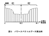
ステップSP4において、スペクトル処理部11は乗算データに対して、高速フーリエ変換(FFT:Fast Fourier Transform)を行うことにより、図5に示すようなパワースペクトルデータを算出し、ステップSP5に移る。
【0039】
ステップSP5において、スペクトル処理部11はパワースペクトルデータから有意であるパワースペクトルデータのみを抽出するようになされている。
【0040】
この抽出処理において、N個の乗算データから算出したパワースペクトルデータのうち、N/2から右側のパワースペクトルデータ群AR2(図5)は、ゼロ値からN/2までの左側のパワースペクトルデータ群AR1(図5)とほぼ同じ成分になる(すなわち、左右対称となる)。このことは、N個の乗算データの周波数帯域内で、両端から等距離にある2個の周波数点におけるパワースペクトルデータの成分が互いに共役であることを示している。従って、スペクトル処理部11は、ゼロ値からN/2までの左側のパワースペクトルデータ群AR1(図5)のみを抽出対象とする。
【0041】
そしてスペクトル処理部11は、このとき抽出対象としたパワースペクトルデータ群AR1のうち、予めユーザが入力手段18(図1及び図2)を介して選択設定した以外のm個のパワースペクトルデータを除いて抽出する。
【0042】
具体的には、ユーザが入力手段18を介して例えば人間の声を一段と高音質にするように選択設定を行った場合、当該選択操作に応じた制御データD18が入力手段18からスペクトル処理部11に出力され(図1及び図2)、これによりスペクトル処理部11は、このとき抽出したパワースペクトルデータ群AR1(図5)から、人間の声において有意となる500Hzから4kHz付近のパワースペクトルデータのみを抽出する(すなわち500Hzから4kHz付近以外のパワースペクトルデータが、除くべきm個のパワースペクトルデータである)。
【0043】
また、ユーザが入力手段18(図1及び図2)を介して例えば音楽を一段と高音質にするように選択を行った場合には、当該選択操作に応じた制御データD18が入力手段18からスペクトル処理部11に出力され、これによりスペクトル処理部11は、このとき抽出したパワースペクトルデータ群AR1(図5)から、音楽において有意となる20Hzから20kHz付近のパワースペクトルデータのみを抽出する(すなわち20Hzから20kHz付近以外のパワースペクトルデータが、除くべきm個のパワースペクトルデータである)。
【0044】
このように入力手段18(図1及び図2)から出力される制御データD18は、有意なパワースペクトルデータとして抽出する周波数成分を決定づけるようになされており、入力手段18(図1及び図2)を介して手動で選択操作するユーザの意図を反映している。
【0045】
従って、制御データD18に応じてパワースペクトルデータを抽出するスペクトル処理部11は、ユーザが高音質での出力を希望する特定のオーディオ成分の周波数成分を有意なパワースペクトルデータとして抽出することとなる。
【0046】
因みに、スペクトル処理部11は、抽出対象としたパワースペクトルデータ群AR1のうち、もとの波形の音程を表すため、有意な特徴をもたない直流成分のパワースペクトルデータをも除いて抽出するようになされている。
【0047】
このように、ステップSP5において、スペクトル処理部11は制御データD18に応じて、パワースペクトルデータ群AR1(図5)からm個のパワースペクトルデータを除くと共に、直流成分のパワースペクトルデータも除いてなる必要最小限のパワースペクトルデータ、すなわち有意なパワースペクトルデータのみを抽出し、続くステップSP6に移る。
【0048】
ステップSP6において、スペクトル処理部11は抽出されたパワースペクトルデータに対して、次式、
【0049】
【数5】
に従って、このとき抽出されたパワースペクトルデータ(ps[k] )の最大値(ps_max)を算出し、次式、
【0051】
【数6】
に従って、このとき抽出されたパワースペクトルデータ(ps[k] )の最大値(ps_max)での正規化(除算)し、このとき得られた基準値(psn[k] )に対して、次式、
【0053】
【数7】
に従って、対数(デシベル値)変換を行うようになされている。
【0055】
因みに(7)式において、logは常用対数である。また対数変換においては、任意の基準値によって、小さな波形をもデシベル値(音圧レベル)として表し得る。従って、例えば大きな波形付近に有意である小さな波形が存在するオーディオデータをスペクトル処理部11が対数変換しなかった場合、当該オーディオデータは一般的に16ビット等の大きなビット数で量子化されていることにより、有意である小さな波形部分が大きな波形にマスキングされてしまう。
【0056】
このため、スペクトル処理部11は、特徴部分(有意である小さな波形部分)を見い出せないことになる。従って、スペクトル処理部11は、対数変換を行うことにより、特徴部分(有意である小さな波形部分)をも見い出すようになされている。
【0057】
また、音感等の刺激に対する人間の感覚は、ほぼその強さの対数に比例するため、対数変換にて表した量(すなわち、デシベル値)は、感覚の度合いを表すことになる。従って、スペクトル処理部11は、対数変換を行うことにより、結果として、音声を聞く対象である人間が心地よく聞き得るようにする。
【0058】
このように、ステップSP6において、スペクトル処理部11は最大振幅で正規化及び振幅の対数変換を行うことにより、特徴部分(有意である小さな波形部分)をも見い出すと共に、結果として、音声を聞く対象である人間が心地よく聞き得るようにする対数データD11を算出し、続くステップSP7に移って対数データ算出処理手順を終了する。
【0059】
このようにして、スペクトル処理部11は対数データ算出方法の対数データ算出処理手順によって、入力オーディオデータD10で表される信号波形の特徴を一段と見い出した対数データD11を算出することができる。
【0060】
次に、図1について上述した予測係数メモリ15に記憶するクラス毎の予測係数のセットを予め学習によって得るための学習回路について説明する。
【0061】
図6において、学習回路30は、高音質の教師オーディオデータD30を生徒信号生成フィルタ37に受ける。生徒信号生成フィルタ37は、間引き率設定信号D39により設定された間引き率で教師オーディオデータD30を所定時間ごとに所定サンプル間引くようになされている。
【0062】
この場合、生徒信号生成フィルタ37における間引き率によって、生成される予測係数が異なり、これに応じて上述のオーディオ信号処理装置10で再現されるオーディオデータも異なる。例えば、上述のオーディオ信号処理装置10においてサンプリング周波数を高くすることでオーディオデータの音質を向上しようとする場合、生徒信号生成フィルタ37ではサンプリング周波数を減らす間引き処理を行う。また、これに対して上述のオーディオ信号処理装置10において入力オーディオデータD10の欠落したデータサンプルを補うことで音質の向上を図る場合には、これに応じて、生徒信号生成フィルタ37ではデータサンプルを欠落させる間引き処理を行うようになされている。
【0063】
かくして、生徒信号生成フィルタ37は教師オーディオデータ30から所定の間引き処理により生徒オーディオデータD37を生成し、これをスペクトル処理部31及び予測演算部抽出部33にそれぞれ供給する。
【0064】
スペクトル処理部31は生徒信号生成フィルタ37から供給された生徒オーディオデータD37を所定時間毎の領域(この実施の形態の場合、例えば6サンプル毎とする)に分割した後、当該分割された各時間領域の波形について、図4について上述した対数データ算出方法による算出結果であってクラス分類しようとする対数データD31を算出し、これをクラス分類部34に供給する。
【0065】
クラス分類部34は、スペクトル処理部31から供給された対数データD31について、当該対数データD31を圧縮して圧縮データパターンを生成するADRC回路部と、対数データD31の属するクラスコードを発生するクラスコード発生回路部とを有する。
【0066】
ADRC回路部は対数データD31に対して、例えば8ビットから2ビットに圧縮するような演算を行うことによりパターン圧縮データを形成する。このADRC回路部は、適応的量子化を行うものであり、ここでは、信号レベルの局所的なパターンを短い語長で効率的に表現することができるので、信号パターンのクラス分類のコード発生用に用いられる。
【0067】
具体的には、6つの8ビットのデータ(対数データ)をクラス分類しようとする場合、248という膨大な数のクラスに分類しなければならず、回路上の負担が多くなる。そこで、この実施の形態のクラス分類部34ではその内部に設けられたADRC回路部で生成されるパターン圧縮データに基づいてクラス分類を行う。例えば6つの対数データに対して1ビットの量子化を実行すると、6つの対数データを6ビットで表すことができ、26 =64クラスに分類することができる。
【0068】
ここで、ADRC回路部は、切り出された領域内のダイナミックレンジをDR、ビット割り当てをm、各対数データのデータレベルをL、量子化コードをQとして、上述の(1)式と同様の演算により、領域内の最大値MAXと最小値MINとの間を指定されたビット長で均等に分割して量子化を行う。かくしてスペクトル処理部31において算出された6つの対数データが、それぞれ例えば8ビット(m=8)で構成されているとすると、これらはADRC回路部においてそれぞれが2ビットに圧縮される。
【0069】
このようにして圧縮された対数データをそれぞれqn (n=1〜6)とすると、クラス分類部34に設けられたクラスコード発生回路部は、圧縮された対数データqn に基づいて、上述の(2)式と同様の演算を実行することにより、そのブロック(q1 〜q6 )が属するクラスを示すクラスコードclass を算出し、当該算出されたクラスコードclass を表すクラスコードデータD34を予測係数算出部36に供給する。因みに(2)式において、nは圧縮された対数データqn の数を表し、この実施の形態の場合n=6であり、またPはビット割り当てを表し、この実施の形態の場合P=2である。
【0070】
このようにして、クラス分類部34はスペクトル処理部31から供給された対数データD31のクラスコードデータD34を生成し、これを予測係数算出部36に供給する。また、予測係数算出部36には、クラスコードデータD34に対応した時間軸領域のオーディオ波形データD33(x1 、x2 、……、xn )が予測演算部抽出部33において切り出されて供給される。
【0071】
予測係数算出部36は、クラス分類部34から供給されたクラスコードclass と、各クラスコードclass 毎に切り出されたオーディオ波形データD33と、入力端TINから供給された高音質の教師オーディオデータD30とを用いて、正規方程式を立てる。
【0072】
すなわち、生徒オーディオデータD37のnサンプルのレベルをそれぞれx1 、x2 、……、xn として、それぞれにpビットのADRCを行った結果の量子化データをq1 、……、qn とする。このとき、この領域のクラスコードclass を上述の(2)式のように定義する。そして、上述のように生徒オーディオデータD37のレベルをそれぞれ、x1 、x2 、……、xn とし、高音質の教師オーディオデータD30のレベルをyとしたとき、クラスコード毎に、予測係数w1 、w2 、……、wn によるnタップの線形推定式を設定する。これを次式、
【0073】
【数8】
とする。学習前は、Wn が未定係数である。
【0075】
学習回路30では、クラスコード毎に、複数のオーディオデータに対して学習を行う。データサンプル数がMの場合、上述の(8)式に従って、次式、
【0076】
【数9】
が設定される。但しk=1、2、……Mである。
【0078】
M>nの場合、予測係数w1 、……wn は一意的に決まらないので、誤差ベクトルeの要素を次式、
【0079】
【数10】
によって定義し(但し、k=1、2、……、M)、次式、
【0081】
【数11】
を最小にする予測係数を求める。いわゆる、最小自乗法による解法である。
【0083】
ここで、(11)式によるwn の偏微分係数を求める。この場合、次式、
【0084】
【数12】
を「0」にするように、各Wn (n=1〜6)を求めれば良い。
【0086】
そして、次式、
【0087】
【数13】
【数14】
のように、Xij、Yi を定義すると、(12)式は行列を用いて次式、
【0090】
【数15】
として表される。
【0092】
この方程式は、一般に正規方程式と呼ばれている。なお、ここではn=6である。
【0093】
全ての学習用データ(教師オーディオデータD30、クラスコードclass 、オーディオ波形データD33)の入力が完了した後、予測係数算出部36は各クラスコードclass に上述の(15)式に示した正規方程式を立てて、この正規方程式を掃き出し法等の一般的な行列解法を用いて、各Wn について解き、各クラスコード毎に、予測係数を算出する。予測係数算出部36は、算出された各予測係数(D36)を予測係数メモリ15に書き込む。
【0094】
このような学習を行った結果、予測係数メモリ15には、量子化データq1 、……、q6 で規定されるパターン毎に、高音質のオーディオデータyを推定するための予測係数が、各クラスコード毎に格納される。この予測係数メモリ15は、図1について上述したオーディオ信号処理装置10において用いられる。かかる処理により、線形推定式に従って通常のオーディオデータから高音質のオーディオデータを作成するための予測係数の学習が終了する。
【0095】
このように、学習回路30は、オーディオ信号処理装置10において補間処理を行う程度を考慮して、生徒信号生成フィルタ37で高音質の教師オーディオデータの間引き処理を行うことにより、オーディオ信号処理装置10における補間処理のための予測係数を生成することができる。
【0096】
以上の構成において、オーディオ信号処理装置10は、入力オーディオデータD10に対して高速フーリエ変換を行うことにより、周波数軸上にパワースペクトルを算出する。周波数分析(高速フーリエ変換)は、時間軸波形データからでは知りえない微妙な違いを発見することが可能であることにより、オーディオ信号処理装置10は、時間軸領域に特徴を見い出せない微妙な特徴を見い出し得るようになる。
【0097】
微妙な特徴を見い出し得る状態(すなわち、パワースペクトルを算出した状態)において、オーディオ信号処理装置10は、選択範囲設定手段(ユーザが入力手段18から手動で行う選択設定)に応じて、有意とされるパワースペクトルデータのみを抽出(すなわち、N/2−m個)する。
【0098】
これによりオーディオ信号処理装置10は、処理負担を一段と軽減することができ、かつ処理速度を向上させることができる。
【0099】
さらに、オーディオ信号処理装置10は、有意とされた必要最小限のパワースペクトルデータに対して、最大振幅で正規化及び振幅の対数変換を行うことにより、対数データを生成する。この対数変換においては、特徴部分(有意である小さな波形部分)をも見い出すと共に、結果として、音声を聞く対象である人間が心地よく聞き得るようにする対数データを生成する。
【0100】
このように、オーディオ信号処理装置10は、周波数分析を行うことにより、微妙な特徴を見い出し得るようになされたパワースペクトルデータから有意とされるパワースペクトルデータのみを抽出し、さらに、抽出したパワースペクトルデータに対して、最大振幅で正規化及び振幅の対数変換を行うことにより得られる対数データに基づいて、そのクラスを特定する。
【0101】
そしてオーディオ信号処理装置10は、抽出した有意なパワースペクトルデータに基づいて特定したクラスに基づく予測係数を用いて入力オーディオデータD10を予測演算することにより、当該入力オーディオデータD10を一段と高音質のオーディオデータD16に変換することができる。
【0102】
また、クラス毎の予測係数を生成する学習時において、位相の異なる多数の教師オーディオデータについてそれぞれに対応した予測係数を求めておくことにより、オーディオ信号処理装置10における入力オーディオデータD10のクラス分類適応処理時に位相変動が生じても、位相変動に対応した処理を行うことができる。
【0103】
以上の構成によれば、周波数分析を行うことにより、微妙な特徴を見い出し得るようになされたパワースペクトルデータから有意とされるパワースペクトルデータのみを抽出し、さらに、抽出したパワースペクトルデータに対して最大振幅で正規化及び振幅の対数変換を行うことにより得た対数データをクラス分類した結果に基づく予測係数を用いて入力オーディオデータD10を予測演算するようにしたことにより、入力オーディオデータD10を一段と高音質のオーディオデータD16に変換することができる。
【0104】
なお上述の実施の形態においては、窓関数としてハミング窓を用いて乗算する場合について述べたが、本発明はこれに限らず、ハミング窓に代えて、例えばハニング窓やブラックマン窓等、他の種々の窓関数によって乗算する、又はスペクトル処理部において予め各種窓関数(ハミング窓、ハニング窓及びブラックマン窓等)を用いて乗算し得るようにしておき、入力されるディジタルオーディオ信号の周波数特性に応じて、スペクトル処理部が所望の窓関数を用いて乗算するようにしても良い。
【0105】
因みに、スペクトル処理部がハニング窓を用いて乗算する場合、スペクトル処理部は、切り出し部から供給されたクラスタップに対して、次式、
【0106】
【数16】
からなるハニング窓を乗算して乗算データを算出する。
【0108】
また、スペクトル処理部がブラックマン窓を使用して乗算する場合、スペクトル処理部は、切り出し部から供給されたクラスタップに対して、次式、
【0109】
【数17】
からなるブラックマン窓を乗算して乗算データを算出する。
【0111】
また上述の実施の形態においては、高速フーリエ変換を用いる場合について述べたが、本発明はこれに限らず、例えば離散フーリエ変換(DFT:Discrete Fourier Transformer)や離散コサイン変換(DCT:Discrete Cosine Transform )や最大エントロピー法、さらには線形予測分析による方法等、他の種々の周波数分析手段を適用することができる。
【0112】
さらに上述の実施の形態においては、スペクトル処理部11がゼロ値からN/2までの左側のパワースペクトルデータ群AR1(図5)のみを抽出対象とする場合について述べたが、本発明はこれに限らず、右側のパワースペクトルデータ群AR2(図5)のみを抽出対象とするようにしても良い。
【0113】
この場合、オーディオ信号処理装置10の処理負担を一段と軽減することができ、処理速度を一段と向上させることができる。
【0114】
さらに上述の実施の形態においては、圧縮データパターンを生成するパターン生成手段として、ADRCを行う場合について述べたが、本発明はこれに限らず、例えば可逆符号化(DPCM:Differential Pulse Code Modulation)やベクトル量子化(VQ:Vector Quantize )等の圧縮手段を用いるようにしても良い。要は、信号波形のパターンを少ないクラスで表現し得るような圧縮手段であれば良い。
【0115】
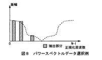
さらに上述の実施の形態においては、ユーザが手動で選択操作し得る選択範囲設定手段として、人間の声及び音声を選択(すなわち、抽出する周波数成分として500Hz〜4kHz又は20Hz〜20kHz)する場合について述べたが、本発明はこれに限らず、例えば図7に示すように、高域(UPP)、中域(MID)及び低域(LOW)のいづれかの周波数成分を選択する、又は図8に示すように、まばらに周波数成分を選択する、さらには図9に示すように、不均一に帯域を周波数成分する等、他の種々の選択範囲設定手段を適用し得る。
【0116】
この場合、オーディオ信号処理装置には、新たに設けられた選択範囲設定手段に対応するプログラムを作成してハードディスクドライブやROM等、所定の記憶手段に格納させる。これにより、ユーザが手動で入力手段18を介して新たに設けられた選択範囲設定手段を選択操作した場合においても、このとき選択された選択範囲設定手段に応じた制御データが入力手段からスペクトル処理部に出力され、これによりスペクトル処理部は、新たに設けられた選択範囲設定手段に対応するプログラムによって、所望の周波数成分からパワースペクトルデータの抽出を行う。
【0117】
このようにすれば、他の種々の選択範囲設定手段を適用することができ、ユーザの意図に応じた有意なパワースペクトルデータを抽出することができる。
【0118】
さらに上述の実施の形態においては、オーディオ信号処理装置10(図2)がプログラムによってクラスコード生成処理手順を実行する場合について述べたが、本発明はこれに限らず、ハードウェア構成によってこれらの機能を実現して種々のディジタル信号処理装置(例えば、レートコンバータ、オーバーサンプリング処理装置、BS(Broadcasting Satellite)放送等に用いられているPCM(Pulse Code Modulation) ディジタル音声エラー訂正を行うPCMエラー修正装置等)内に設けたり、又は各機能を実現するプログラムを格納したプログラム格納媒体(フロッピーディスク、光ディスク等)からこれらのプログラムを種々のディジタル信号処理装置にロードして各機能部を実現するようにしても良い。
【0119】
【発明の効果】
上述のように本発明によれば、ディジタルオーディオ信号からパワースペクトルデータを算出し、算出されたパワースペクトルデータを最大値幅で正規化して正規化データを算出し、算出された正規化データに基づいてそのクラスを分類し、分類されたクラスに対応した予測方式でディジタルオーディオ信号を変換するようにしたことにより、一段とディジタルオーディオ信号の特徴に適応した変換を行うことができ、かくして、ディジタルオーディオ信号の波形再現性を一段と向上した高音質のディジタルオーディオ信号への変換を行うことができる。
【図面の簡単な説明】
【図1】本発明によるオーディオ信号処理装置を示す機能ブロック図である。
【図2】本発明によるオーディオ信号処理装置を示すブロック図である。
【図3】オーディオデータの変換処理手順を示すフローチャートである。
【図4】対数データ算出処理手順を示すフローチャートである。
【図5】パワースペクトルデータ算出例を示す略線図である。
【図6】学習回路の構成を示すブロック図である。
【図7】パワースペクトルデータ選択例を示す略線図である。
【図8】パワースペクトルデータ選択例を示す略線図である。
【図9】パワースペクトルデータ選択例を示す略線図である。
【符号の説明】
10……オーディオ信号処理装置、11……スペクトル処理部、22……ROM、15……RAM、24……通信インターフェース、25……ハードディスクドライブ、26……入力手段、27……データ入出力部、28……リムーバブルドライブ。[0001]
BACKGROUND OF THE INVENTION
The present invention relates to a digital signal processing method, a learning method, an apparatus for the same, and a program storage medium, and relates to a digital signal processing method for performing data interpolation processing on a digital signal in a rate converter or a PCM (Pulse Code Modulation) decoding device, and learning The present invention is suitable for application to methods and their apparatuses and program storage media.
[0002]
[Prior art]
Conventionally, before a digital audio signal is input to a digital / analog converter, an oversampling process for converting the sampling frequency to several times the original value is performed. This allows the digital audio signal output from the digital / analog converter to maintain the phase characteristics of the analog anti-alias filter at a high audible frequency range and eliminates the effects of digital image noise associated with sampling. It is made to be done.
[0003]
In such oversampling processing, a digital filter of a linear primary (linear) interpolation method is usually used. Such a digital filter obtains an average value of a plurality of existing data and generates linear interpolation data when the sampling rate changes or data is lost.
[0004]
[Problems to be solved by the invention]
However, the digital audio signal after the oversampling process has a data amount that is several times denser in the time axis direction by linear linear interpolation, but the frequency band of the digital audio signal after the oversampling process is the same as that before the conversion. It has not changed much, and the sound quality itself has not improved. Furthermore, since the interpolated data is not necessarily generated based on the waveform of the analog audio signal before A / D conversion, the waveform reproducibility is hardly improved.
[0005]
In addition, when dubbing digital audio signals with different sampling frequencies, the frequency is converted using a sampling rate converter. Even in such a case, only linear data interpolation can be performed using a linear primary digital filter. Therefore, it was difficult to improve sound quality and waveform reproducibility. Further, the same applies when a data sample of the digital audio signal is lost.
[0006]
The present invention has been made in view of the above points, and intends to propose a digital signal processing method, a learning method, an apparatus thereof, and a program storage medium that can further improve the waveform reproducibility of a digital audio signal. .
[0007]
[Means for Solving the Problems]
In order to solve such a problem, in the present invention, power spectrum data is calculated from a digital audio signal, the calculated power spectrum data is normalized with a maximum value width to calculate normalized data, and the calculated normalized data is based on the calculated normalized data. Then, by classifying the class and converting the digital audio signal by a prediction method corresponding to the classified class, it is possible to perform the conversion more adapted to the characteristics of the digital audio signal.
[0008]
DETAILED DESCRIPTION OF THE INVENTION
Hereinafter, an embodiment of the present invention will be described in detail with reference to the drawings.
[0009]
In FIG. 1, an audio
[0010]
Incidentally, the audio data in this embodiment is musical sound data representing human voices, musical instrument sounds, and the like, and data representing various other sounds.
[0011]
That is, in the audio
[0012]
The
[0013]
The
[0014]
The ADRC circuit unit forms pattern compressed data by performing an operation for compressing the logarithmic data D11 from, for example, 8 bits to 2 bits. This ADRC circuit unit performs adaptive quantization. Here, since a local pattern of a signal level can be efficiently expressed with a short word length, it is used for generating a code for classifying a signal pattern. Used for.
[0015]
Specifically, when classifying 6 8-bit data (logarithmic data), 2 48 Therefore, the burden on the circuit increases. Therefore, the
[0016]
Here, when the dynamic range in the extracted region is DR, the bit allocation is m, the data level of each logarithmic data is L, and the quantization code is Q, the ADRC circuit unit has the following formula:
[0017]
[Expression 1]
Accordingly, the quantization is performed by equally dividing the maximum value MAX and the minimum value MIN in the region with the designated bit length. In the expression (1), {} means a rounding process after the decimal point. Thus, if the six logarithmic data calculated in the
[0019]
Each log data compressed in this way is q n Assuming that (n = 1 to 6), the class code generation circuit provided in the
[0020]
[Expression 2]
By executing the operation shown in FIG. 1 ~ Q 6 ) Is calculated, and class code data D14 representing the calculated class code class is supplied to the
[0022]
In this way, the
[0023]
In the
[0024]
The
[0025]
[Equation 3]
The prediction result y ′ is obtained by performing the product-sum operation shown in FIG. The predicted value y ′ is output from the
[0027]
Although the functional block described above with reference to FIG. 1 is shown as the configuration of the audio
[0028]
The audio
[0029]
The user inputs various commands via the input means 18 such as a keyboard or a mouse, thereby causing the CPU 21 to execute the class classification process described above with reference to FIG. In this case, the audio
[0030]
Incidentally, FIG. 3 shows a processing procedure of the class classification adaptive processing in the audio
[0031]
The calculated logarithmic data D11 represents the characteristics of the input audio data D10, and the audio
[0032]
The prediction coefficient read from the
[0033]
Next, a method for calculating the logarithmic data D11 of the input audio data D10 in the
[0034]
That is, FIG. 4 shows a logarithmic data calculation processing procedure of the logarithmic data calculation method in the
[0035]
In step SP3, when the
[0036]
[Expression 4]
The multiplication data is calculated according to the Hamming window shown in FIG. Incidentally, in the window function multiplication processing, in order to improve the accuracy of the frequency analysis performed in the subsequent step SP4, the first value and the last value of each class tap constructed at this time are made equal. ing. In equation (1), “N” represents the number of samples in the Hamming window, and “k” represents what number of sample data.
[0038]
In step SP4, the
[0039]
In step SP5, the
[0040]
In this extraction process, among the power spectrum data calculated from N multiplication data, the power spectrum data group AR2 on the right side from N / 2 (FIG. 5) is the power spectrum data group on the left side from zero value to N / 2. The component is almost the same as that of AR1 (FIG. 5) (that is, symmetrical). This indicates that the components of the power spectrum data at two frequency points equidistant from both ends within the frequency band of N multiplication data are conjugate to each other. Therefore, the
[0041]
Then, the
[0042]
More specifically, when the user performs selection setting so that, for example, the human voice is further improved in sound quality via the
[0043]
In addition, when the user makes a selection through the input unit 18 (FIGS. 1 and 2) so that, for example, music has a higher sound quality, control data D18 corresponding to the selection operation is transmitted from the
[0044]
Thus, the control data D18 output from the input means 18 (FIGS. 1 and 2) determines the frequency components to be extracted as significant power spectrum data, and the input means 18 (FIGS. 1 and 2). This reflects the intention of the user who manually performs the selection operation.
[0045]
Therefore, the
[0046]
Incidentally, the
[0047]
In this way, in step SP5, the
[0048]
In step SP6, the
[0049]
[Equation 5]
The maximum value (ps_max) of the power spectrum data (ps [k]) extracted at this time is calculated according to
[0051]
[Formula 6]
The power spectrum data (ps [k]) extracted at this time is normalized (divided) by the maximum value (ps_max), and the following value is obtained for the reference value (psn [k]) obtained at this time: ,
[0053]
[Expression 7]
Logarithmic (decibel value) conversion is performed according to the above.
[0055]
Incidentally, in the equation (7), log is a common logarithm. In logarithmic conversion, a small waveform can be expressed as a decibel value (sound pressure level) by an arbitrary reference value. Therefore, for example, when the
[0056]
For this reason, the
[0057]
In addition, since the human sensation with respect to stimuli such as a sense of sound is substantially proportional to the logarithm of its strength, the amount represented by logarithmic transformation (ie, decibel value) represents the degree of sensation. Therefore, the
[0058]
As described above, in step SP6, the
[0059]
In this way, the
[0060]
Next, a learning circuit for obtaining in advance a set of prediction coefficients for each class stored in the
[0061]
In FIG. 6, the
[0062]
In this case, the generated prediction coefficient differs depending on the decimation rate in the student
[0063]
Thus, the student
[0064]
The spectrum processing unit 31 divides the student audio data D37 supplied from the student
[0065]
The
[0066]
The ADRC circuit unit performs pattern compression data on the logarithmic data D31 by performing an operation such as compression from 8 bits to 2 bits. This ADRC circuit unit performs adaptive quantization. Here, since a local pattern of a signal level can be efficiently expressed with a short word length, it is used for generating a code for classifying a signal pattern. Used for.
[0067]
Specifically, when classifying 6 8-bit data (logarithmic data), 2 48 Therefore, the burden on the circuit increases. Therefore, the
[0068]
Here, the ADRC circuit unit calculates the dynamic range in the extracted area as DR, bit allocation as m, data level of each logarithmic data as L, and quantization code as Q. Thus, quantization is performed by equally dividing the maximum value MAX and the minimum value MIN in the region with the designated bit length. Thus, if the six logarithmic data calculated in the spectrum processing unit 31 are each composed of, for example, 8 bits (m = 8), these are each compressed to 2 bits in the ADRC circuit unit.
[0069]
Each log data compressed in this way is q n Assuming that (n = 1 to 6), the class code generation circuit unit provided in the
[0070]
In this way, the
[0071]
The prediction
[0072]
That is, the n sample levels of the student audio data D37 are set to x respectively. 1 , X 2 , ..., x n Quantized data obtained as a result of ADRC of p bits for each 1 , ..., q n And At this time, the class code class of this area is defined as in the above-described equation (2). Then, as described above, the level of the student audio data D37 is set to x, respectively. 1 , X 2 , ..., x n When the level of the high-quality teacher audio data D30 is y, the prediction coefficient w for each class code 1 , W 2 , ..., w n Set an n-tap linear estimation formula. This is expressed as
[0073]
[Equation 8]
And Before learning, W n Is an undetermined coefficient.
[0075]
The
[0076]
[Equation 9]
Is set. However, k = 1, 2,...
[0078]
When M> n, the prediction coefficient w 1 , …… w n Is not uniquely determined, so the elements of the error vector e are
[0079]
[Expression 10]
(Where k = 1, 2,..., M),
[0081]
## EQU11 ##
Find the prediction coefficient that minimizes. This is a so-called least square method.
[0083]
Where w according to equation (11) n Find the partial differential coefficient of. In this case,
[0084]
[Expression 12]
Each W so that n What is necessary is just to obtain | require (n = 1-6).
[0086]
And the following formula:
[0087]
[Formula 13]
[Expression 14]
X ij , Y i Is defined using the matrix as follows:
[0090]
[Expression 15]
Represented as:
[0092]
This equation is generally called a normal equation. Here, n = 6.
[0093]
After the input of all the learning data (teacher audio data D30, class code class, audio waveform data D33) is completed, the prediction
[0094]
As a result of such learning, the
[0095]
In this way, the
[0096]
In the above configuration, the audio
[0097]
In a state where a subtle feature can be found (that is, a state where a power spectrum is calculated), the audio
[0098]
As a result, the audio
[0099]
Furthermore, the audio
[0100]
As described above, the audio
[0101]
Then, the audio
[0102]
Also, in learning to generate a prediction coefficient for each class, by applying a prediction coefficient corresponding to each of a large number of teacher audio data having different phases, the classification of the input audio data D10 in the audio
[0103]
According to the above configuration, by performing frequency analysis, only significant power spectrum data is extracted from power spectrum data that can be used to find subtle features, and the extracted power spectrum data is further extracted. By predicting the input audio data D10 using a prediction coefficient based on the result of classifying logarithmic data obtained by performing normalization and logarithmic conversion of the amplitude with the maximum amplitude, the input audio data D10 is further improved. It can be converted into high-quality audio data D16.
[0104]
In the above-described embodiment, the case where multiplication is performed using a Hamming window as the window function has been described. However, the present invention is not limited to this, and instead of the Hamming window, for example, another Hanning window, Blackman window, or the like can be used. Multiply by various window functions, or make it possible to multiply in advance by using various window functions (Humming window, Hanning window, Blackman window, etc.) in the spectrum processing unit, and adjust the frequency characteristics of the input digital audio signal. Accordingly, the spectrum processing unit may perform multiplication using a desired window function.
[0105]
Incidentally, when the spectrum processing unit performs multiplication using the Hanning window, the spectrum processing unit performs the following expression on the class tap supplied from the clipping unit:
[0106]
[Expression 16]
Multiplication data is calculated by multiplying the Hanning window.
[0108]
Further, when the spectrum processing unit multiplies using the Blackman window, the spectrum processing unit, for the class tap supplied from the clipping unit,
[0109]
[Expression 17]
Multiplication data is calculated by multiplying the Blackman window.
[0111]
In the above-described embodiment, the case where the fast Fourier transform is used has been described. However, the present invention is not limited to this, and for example, the discrete Fourier transform (DFT) or the discrete cosine transform (DCT). Various other frequency analysis means such as the maximum entropy method and the method based on linear prediction analysis can be applied.
[0112]
Furthermore, in the above-described embodiment, the case where the
[0113]
In this case, the processing load on the audio
[0114]
Furthermore, in the above-described embodiment, the case where ADRC is performed as a pattern generation unit that generates a compressed data pattern has been described. However, the present invention is not limited to this, and for example, lossless encoding (DPCM: Differential Pulse Code Modulation) You may make it use compression means, such as vector quantization (VQ: Vector Quantize). In short, any compression means that can express signal waveform patterns in a small number of classes may be used.
[0115]
Furthermore, in the above-described embodiment, a case where a human voice and voice are selected (that is, 500 Hz to 4 kHz or 20 Hz to 20 kHz as a frequency component to be extracted) as selection range setting means that can be manually selected by the user is described. However, the present invention is not limited to this. For example, as shown in FIG. 7, one of the frequency components of the high frequency range (UPP), the mid frequency range (MID), and the low frequency range (LOW) is selected or shown in FIG. As described above, various other selection range setting means such as sparsely selecting frequency components, and non-uniformly frequency components of bands as shown in FIG. 9, can be applied.
[0116]
In this case, the audio signal processing apparatus creates a program corresponding to the newly provided selection range setting means and stores it in a predetermined storage means such as a hard disk drive or ROM. Thus, even when the user manually selects and operates the selection range setting means newly provided via the input means 18, the control data corresponding to the selection range setting means selected at this time is transmitted from the input means to the spectrum process. Thus, the spectrum processing unit extracts power spectrum data from a desired frequency component by a program corresponding to the newly provided selection range setting means.
[0117]
If it does in this way, other various selection range setting means can be applied, and significant power spectrum data according to a user's intention can be extracted.
[0118]
Further, in the above-described embodiment, the case where the audio signal processing apparatus 10 (FIG. 2) executes the class code generation processing procedure by a program has been described. However, the present invention is not limited to this, and these functions are determined depending on the hardware configuration. Various digital signal processing devices (for example, rate converters, oversampling processing devices, PCM error correction devices that perform PCM (Pulse Code Modulation) digital audio error correction used in BS (Broadcasting Satellite) broadcasting, etc.) These programs are loaded into various digital signal processing devices from a program storage medium (floppy disk, optical disk, etc.) that is provided in the program or stores programs that realize the functions. Also good.
[0119]
【The invention's effect】
As described above, according to the present invention, the power spectrum data is calculated from the digital audio signal, the calculated power spectrum data is normalized by the maximum value width, the normalized data is calculated, and based on the calculated normalized data. By classifying the class and converting the digital audio signal by the prediction method corresponding to the classified class, it is possible to perform the conversion more adapted to the characteristics of the digital audio signal, and thus the digital audio signal. Conversion to a high-quality digital audio signal with improved waveform reproducibility can be performed.
[Brief description of the drawings]
FIG. 1 is a functional block diagram showing an audio signal processing apparatus according to the present invention.
FIG. 2 is a block diagram showing an audio signal processing apparatus according to the present invention.
FIG. 3 is a flowchart showing a procedure for converting audio data.
FIG. 4 is a flowchart showing a logarithmic data calculation processing procedure.
FIG. 5 is a schematic diagram illustrating an example of calculating power spectrum data.
FIG. 6 is a block diagram illustrating a configuration of a learning circuit.
FIG. 7 is a schematic diagram showing an example of power spectrum data selection.
FIG. 8 is a schematic diagram showing an example of power spectrum data selection.
FIG. 9 is a schematic diagram illustrating an example of power spectrum data selection.
[Explanation of symbols]
DESCRIPTION OF
Claims (20)
上記パワースペクトルデータを最大値幅で正規化する正規化ステップと、
正規化されたパワースペクトルデータに基づいてそのクラスを分類するクラス分類ステップと、
分類されたクラスに対応した予測方式で上記ディジタルオーディオ信号を演算することにより上記ディジタルオーディオ信号を変換する予測演算ステップと
を有するディジタル信号処理方法。A frequency analysis step of calculating the power spectrum data from the de-I digital audio signal,
A normalization step that turn into normal the power spectrum data at maximum bandwidth,
A classification step of classifying the class based on the normalized power spectrum data,
Digital signal processing method and a prediction calculating step it converts the digital audio signal by predictive scheme corresponding to classified classes that computation of the digital audio signal.
をさらに有し、
上記正規化ステップは、
上記スペクトルデータ抽出ステップで抽出されるパワースペクトルデータを最大値幅で正規化する
請求項1に記載のディジタル信号処理方法。Spectral data extraction step for extracting a part of the power spectrum data calculated in the frequency analysis step
Further comprising
The normalization step is
Normalize the power spectrum data extracted in the above spectral data extraction step with the maximum value width.
Digital signal processing method according to 請 Motomeko 1.
直流成分のパワースペクトルデータが抽出対象として除外される
請求項1に記載のディジタル信号処理方法。 In the spectral data extraction step,
Power spectrum data of the DC component is excluded as an extraction target
Digital signal processing method according to 請 Motomeko 1.
予め所望とするディジタルオーディオ信号に基づいて学習により生成されている予測係数が用いられる
請求項1に記載のディジタル信号処理方法。In the prediction calculation step,
Prediction coefficients generated by learning based on a desired digital audio signal are used.
Digital signal processing method according to 請 Motomeko 1.
N個のパワースペクトルデータのうち、ゼロからN/2個まで又はN/2個からNまでのパワースペクトルデータが抽出対象とされる
請求項1に記載のディジタル信号処理方法。In the spectral data extraction step,
Among N power spectrum data , power spectrum data from zero to N / 2 or N / 2 to N is selected as an extraction target.
Digital signal processing method according to 請 Motomeko 1.
上記パワースペクトルデータを最大値幅で正規化して正規化する正規化手段と、
正規化されたパワースペクトルデータに基づいてそのクラスを分類するクラス分類手段と、
分類されたクラスに対応した予測方式で上記ディジタルオーディオ信号を演算することにより上記ディジタルオーディオ信号を変換する予測演算手段と
を具えるディジタル信号処理装置。A frequency analyzing means for calculating the power spectrum data from the de-I digital audio signal,
A normalizing means that turn into regular normalized to the maximum width of the power spectrum data,
And class classification means for classifying the class based on the normalized power spectrum data,
Lud Ijitaru signal processing apparatus comprising a prediction arithmetic means you convert the digital audio signal by predictive scheme corresponding to classified classes that computation of the digital audio signal.
をさらに具え、
上記正規化手段は、
上記スペクトルデータ抽出手段で抽出されるパワースペクトルデータを最大値幅で正規化する
請求項6に記載のディジタル信号処理装置。Spectral data extraction means for extracting a part of the power spectrum data calculated in the frequency analysis step
Further comprising
The normalization means is
The power spectrum data extracted by the spectrum data extracting means is normalized with the maximum value width.
Digital signal processing apparatus according to 請 Motomeko 6.
直流成分のパワースペクトルデータを抽出対象として除く
請求項6に記載のディジタル信号処理装置。 The spectral data extraction means includes:
Excluding the power spectral data of the DC component as an extraction target
Digital signal processing apparatus according to 請 Motomeko 6.
予め所望とするディジタルオーディオ信号に基づいて学習により生成されている予測係数を用いる
請求項6に記載のディジタル信号処理装置。The prediction calculation means is
Use prediction coefficients generated by learning based on the desired digital audio signal
Digital signal processing apparatus according to 請 Motomeko 6.
N個のパワースペクトルデータのうち、ゼロからN/2個まで又はN/2個からNまでのパワースペクトルデータを抽出対象とする
請求項6に記載のディジタル信号処理装置。The spectral data extraction means includes:
Out of N power spectrum data , power spectrum data from zero to N / 2 or N / 2 to N is extracted.
Digital signal processing apparatus according to 請 Motomeko 6.
ディジタルオーディオ信号からパワースペクトルデータを算出すること、
上記パワースペクトルデータを最大値幅で正規化すること、
正規化されたパワースペクトルデータに基づいてそのクラスを分類すること、
分類されたクラスに対応した予測方式で上記ディジタルオーディオ信号を演算することにより上記ディジタルオーディオ信号を変換すること
を実行させるプログラムが格納されるプログラム格納媒体。 Against the computer,
Calculating the power spectrum data from the de-I digital audio signal,
It that turn into normal the power spectrum data at maximum bandwidth,
Classifying the class based on the normalized power spectrum data,
Program storage medium in which the program for executing the you convert the digital audio signal in a prediction method corresponding to the classified class by computation the digital audio signal is stored.
ディジタルオーディオ信号から当該ディジタルオーディオ信号を劣化させた生徒ディジタルオーディオ信号を生成する生徒ディジタルオーディオ信号生成ステップと、
上記生徒ディジタルオーディオ信号からパワースペクトルデータを算出する周波数分析ステップと、
上記パワースペクトルデータを最大値幅で正規化する正規化ステップと、
正規化されたパワースペクトルデータに基づいてそのクラスを分類するクラス分類ステップと、
上記ディジタルオーディオ信号と上記生徒ディジタルオーディオ信号とに基づいて上記クラスに対応する予測係数を算出する予測係数算出ステップと
を有する学習方法。In the learning method for generating prediction coefficients used in prediction of the conversion process that converts the digital audio signal,
And the student digital audio signal generation step of generating a student digital audio signal from the de-I digital audio signals degrade the digital audio signal,
A frequency analysis step of calculating power spectrum data from the student digital audio signal;
A normalization step that turn into normal the power spectrum data at maximum bandwidth,
A classification step of classifying the class based on the normalized power spectrum data,
Learning method and a prediction coefficient calculation step of calculating the prediction coefficients corresponding to the class based on the above digital audio signal and the student digital audio signal.
をさらに有し、
上記正規化ステップは、
上記スペクトルデータ抽出ステップで抽出されるパワースペクトルデータを最大値幅で正規化する
請求項12に記載の学習方法。Spectral data extraction step for extracting a part of the power spectrum data calculated in the frequency analysis step
Further comprising
The normalization step is
Normalize the power spectrum data extracted in the above spectral data extraction step with the maximum value width.
Learning method according to 請 Motomeko 12.
直流成分のパワースペクトルデータが抽出対象として除外される
請求項12に記載の学習方法。 In the spectral data extraction step,
Power spectrum data of the DC component is excluded as an extraction target
Learning method according to 請 Motomeko 12.
N個のパワースペクトルデータのうち、ゼロからN/2個まで又はN/2個からNまでのパワースペクトルデータが抽出対象とされる
請求項12に記載の学習方法。In the spectral data extraction step,
Among N power spectrum data , power spectrum data from zero to N / 2 or N / 2 to N is selected as an extraction target.
Learning method according to 請 Motomeko 12.
所望とするディジタルオーディオ信号から当該ディジタルオーディオ信号を劣化させた生徒ディジタルオーディオ信号を生成する生徒ディジタルオーディオ信号生成手段と、
上記生徒ディジタルオーディオ信号からパワースペクトルデータを算出する周波数分析手段と、
上記パワースペクトルデータを最大値幅で正規化する正規化手段と、
正規化されたパワースペクトルデータに基づいてそのクラスを分類するクラス分類手段と、
上記ディジタルオーディオ信号と上記生徒ディジタルオーディオ信号とに基づいて上記クラスに対応する予測係数を算出する予測係数算出手段と
を具える学習装置。In the learning apparatus for generating prediction coefficients used for prediction calculation of conversion processing that converts the digital audio signal,
Student digital audio signal generating means for generating a student digital audio signal obtained by degrading the digital audio signal from a desired digital audio signal;
Frequency analysis means for calculating power spectrum data from the student digital audio signal;
A normalizing means that turn into normal the power spectrum data at maximum bandwidth,
And class classification means for classifying the class based on the normalized power spectrum data,
The digital audio signal and comprises Ru learning apparatus and a prediction coefficient calculating means for calculating the prediction coefficients corresponding to the class based on the above student digital audio signal.
をさらに具え、
上記正規化手段は、
上記スペクトルデータ抽出手段で抽出されるパワースペクトルデータを最大値幅で正規化する
請求項16に記載の学習装置。Spectral data extraction means for extracting a part of the power spectrum data calculated in the frequency analysis step
Further comprising
The normalization means is
The power spectrum data extracted by the spectrum data extracting means is normalized with the maximum value width.
Learning device according to 請 Motomeko 16.
直流成分のパワースペクトルデータを抽出対象として除く
請求項16に記載の学習装置。 The spectral data extraction means includes:
Excluding the power spectral data of the DC component as an extraction target
Learning device according to 請 Motomeko 16.
N個のパワースペクトルデータのうち、ゼロからN/2個まで又はN/2個からNまでのパワースペクトルデータを抽出対象とする
請求項16に記載の学習装置。The spectral data extraction means includes:
Out of N power spectrum data , power spectrum data from zero to N / 2 or N / 2 to N is extracted.
Learning device according to 請 Motomeko 16.
ディジタルオーディオ信号から当該ディジタルオーディオ信号を劣化させた生徒ディジタルオーディオ信号を生成すること、
上記生徒ディジタルオーディオ信号からパワースペクトルデータを算出すること、
上記パワースペクトルデータを最大値幅で正規化すること、
正規化されたパワースペクトルデータに基づいてそのクラスを分類すること、
上記ディジタルオーディオ信号と上記生徒ディジタルオーディオ信号とに基づいて上記クラスに対応する予測係数を算出すること
を実行させるプログラムが格納されるプログラム格納媒体。 Against the computer,
Generating a student digital audio signal from the de-I digital audio signals degrade the digital audio signal,
Calculating the power spectrum data from the student digital audio signal,
It that turn into normal the power spectrum data at maximum bandwidth,
Classifying the class based on the normalized power spectrum data,
Program storage medium in which the program for executing calculating the prediction coefficients corresponding to the class based on the above digital audio signal and the student digital audio signals are stored.
Priority Applications (1)
| Application Number | Priority Date | Filing Date | Title |
|---|---|---|---|
| JP2000238898A JP4645869B2 (en) | 2000-08-02 | 2000-08-02 | DIGITAL SIGNAL PROCESSING METHOD, LEARNING METHOD, DEVICE THEREOF, AND PROGRAM STORAGE MEDIUM |
Applications Claiming Priority (1)
| Application Number | Priority Date | Filing Date | Title |
|---|---|---|---|
| JP2000238898A JP4645869B2 (en) | 2000-08-02 | 2000-08-02 | DIGITAL SIGNAL PROCESSING METHOD, LEARNING METHOD, DEVICE THEREOF, AND PROGRAM STORAGE MEDIUM |
Publications (3)
| Publication Number | Publication Date |
|---|---|
| JP2002049399A JP2002049399A (en) | 2002-02-15 |
| JP2002049399A5 JP2002049399A5 (en) | 2007-04-05 |
| JP4645869B2 true JP4645869B2 (en) | 2011-03-09 |
Family
ID=18730529
Family Applications (1)
| Application Number | Title | Priority Date | Filing Date |
|---|---|---|---|
| JP2000238898A Expired - Fee Related JP4645869B2 (en) | 2000-08-02 | 2000-08-02 | DIGITAL SIGNAL PROCESSING METHOD, LEARNING METHOD, DEVICE THEREOF, AND PROGRAM STORAGE MEDIUM |
Country Status (1)
| Country | Link |
|---|---|
| JP (1) | JP4645869B2 (en) |
Families Citing this family (6)
| Publication number | Priority date | Publication date | Assignee | Title |
|---|---|---|---|---|
| JP4988716B2 (en) | 2005-05-26 | 2012-08-01 | エルジー エレクトロニクス インコーポレイティド | Audio signal decoding method and apparatus |
| US8577686B2 (en) | 2005-05-26 | 2013-11-05 | Lg Electronics Inc. | Method and apparatus for decoding an audio signal |
| WO2007083959A1 (en) | 2006-01-19 | 2007-07-26 | Lg Electronics Inc. | Method and apparatus for processing a media signal |
| CN104681030B (en) | 2006-02-07 | 2018-02-27 | Lg电子株式会社 | Apparatus and method for encoding/decoding signal |
| JP6010539B2 (en) * | 2011-09-09 | 2016-10-19 | パナソニック インテレクチュアル プロパティ コーポレーション オブ アメリカPanasonic Intellectual Property Corporation of America | Encoding device, decoding device, encoding method, and decoding method |
| CN115937282B (en) * | 2023-01-10 | 2024-08-02 | 郑州思昆生物工程有限公司 | Registration method, device, equipment and storage medium of fluorescence image |
Citations (8)
| Publication number | Priority date | Publication date | Assignee | Title |
|---|---|---|---|---|
| JPH01204538A (en) * | 1988-02-10 | 1989-08-17 | Kokusai Denshin Denwa Co Ltd <Kdd> | Vector quantizing system |
| JPH07147566A (en) * | 1993-11-24 | 1995-06-06 | Nec Corp | Sound signal transmitter |
| JPH07321662A (en) * | 1994-05-28 | 1995-12-08 | Sony Corp | Digital signal processing unit and its method |
| JPH08265711A (en) * | 1995-03-22 | 1996-10-11 | Sony Corp | Signal converter and signal conversion method |
| JPH08275120A (en) * | 1995-03-31 | 1996-10-18 | Sony Corp | Image signal conversion method, image signal converter and image signal transmitter |
| JPH09167240A (en) * | 1995-12-15 | 1997-06-24 | Sony Corp | Digital image signal processing device and method therefor |
| JPH10313251A (en) * | 1997-05-12 | 1998-11-24 | Sony Corp | Device and method for audio signal conversion, device and method for prediction coefficeint generation, and prediction coefficeint storage medium |
| JPH113094A (en) * | 1997-06-12 | 1999-01-06 | Kobe Steel Ltd | Noise eliminating device |
-
2000
- 2000-08-02 JP JP2000238898A patent/JP4645869B2/en not_active Expired - Fee Related
Patent Citations (8)
| Publication number | Priority date | Publication date | Assignee | Title |
|---|---|---|---|---|
| JPH01204538A (en) * | 1988-02-10 | 1989-08-17 | Kokusai Denshin Denwa Co Ltd <Kdd> | Vector quantizing system |
| JPH07147566A (en) * | 1993-11-24 | 1995-06-06 | Nec Corp | Sound signal transmitter |
| JPH07321662A (en) * | 1994-05-28 | 1995-12-08 | Sony Corp | Digital signal processing unit and its method |
| JPH08265711A (en) * | 1995-03-22 | 1996-10-11 | Sony Corp | Signal converter and signal conversion method |
| JPH08275120A (en) * | 1995-03-31 | 1996-10-18 | Sony Corp | Image signal conversion method, image signal converter and image signal transmitter |
| JPH09167240A (en) * | 1995-12-15 | 1997-06-24 | Sony Corp | Digital image signal processing device and method therefor |
| JPH10313251A (en) * | 1997-05-12 | 1998-11-24 | Sony Corp | Device and method for audio signal conversion, device and method for prediction coefficeint generation, and prediction coefficeint storage medium |
| JPH113094A (en) * | 1997-06-12 | 1999-01-06 | Kobe Steel Ltd | Noise eliminating device |
Also Published As
| Publication number | Publication date |
|---|---|
| JP2002049399A (en) | 2002-02-15 |
Similar Documents
| Publication | Publication Date | Title |
|---|---|---|
| RU2555221C2 (en) | Complex transformation channel coding with broadband frequency coding | |
| US20090204397A1 (en) | Linear predictive coding of an audio signal | |
| JP2002041089A (en) | Frequency-interpolating device, method of frequency interpolation and recording medium | |
| CN114550732B (en) | Coding and decoding method and related device for high-frequency audio signal | |
| JPH10319996A (en) | Efficient decomposition of noise and periodic signal waveform in waveform interpolation | |
| JP2001343997A (en) | Method and device for encoding digital acoustic signal and recording medium | |
| JP2003108197A (en) | Audio signal decoding device and audio signal encoding device | |
| JP3087814B2 (en) | Acoustic signal conversion encoding device and decoding device | |
| JP4645869B2 (en) | DIGITAL SIGNAL PROCESSING METHOD, LEARNING METHOD, DEVICE THEREOF, AND PROGRAM STORAGE MEDIUM | |
| JP4359949B2 (en) | Signal encoding apparatus and method, and signal decoding apparatus and method | |
| JP4596196B2 (en) | Digital signal processing method, learning method and apparatus, and program storage medium | |
| JP4596197B2 (en) | Digital signal processing method, learning method and apparatus, and program storage medium | |
| US6990475B2 (en) | Digital signal processing method, learning method, apparatus thereof and program storage medium | |
| JP3472279B2 (en) | Speech coding parameter coding method and apparatus | |
| CN1198397C (en) | Decoder, decoding method and program publishing medium | |
| JP2002041098A (en) | Frequency thinning device, frequency thinning method and recording medium | |
| JP3353266B2 (en) | Audio signal conversion coding method | |
| JP2001184090A (en) | Signal encoding device and signal decoding device, and computer-readable recording medium with recorded signal encoding program and computer-readable recording medium with recorded signal decoding program | |
| JP4645866B2 (en) | DIGITAL SIGNAL PROCESSING METHOD, LEARNING METHOD, DEVICE THEREOF, AND PROGRAM STORAGE MEDIUM | |
| JP4645867B2 (en) | DIGITAL SIGNAL PROCESSING METHOD, LEARNING METHOD, DEVICE THEREOF, AND PROGRAM STORAGE MEDIUM | |
| WO2003056546A1 (en) | Signal coding apparatus, signal coding method, and program | |
| JP4645868B2 (en) | DIGITAL SIGNAL PROCESSING METHOD, LEARNING METHOD, DEVICE THEREOF, AND PROGRAM STORAGE MEDIUM | |
| JP4618823B2 (en) | Signal encoding apparatus and method | |
| JP3453116B2 (en) | Audio encoding method and apparatus | |
| JPH0651800A (en) | Data quantity converting method |
Legal Events
| Date | Code | Title | Description |
|---|---|---|---|
| A521 | Request for written amendment filed |
Free format text: JAPANESE INTERMEDIATE CODE: A523 Effective date: 20070220 |
|
| A621 | Written request for application examination |
Free format text: JAPANESE INTERMEDIATE CODE: A621 Effective date: 20070220 |
|
| A977 | Report on retrieval |
Free format text: JAPANESE INTERMEDIATE CODE: A971007 Effective date: 20090929 |
|
| A131 | Notification of reasons for refusal |
Free format text: JAPANESE INTERMEDIATE CODE: A131 Effective date: 20091203 |
|
| A521 | Request for written amendment filed |
Free format text: JAPANESE INTERMEDIATE CODE: A523 Effective date: 20100106 |
|
| TRDD | Decision of grant or rejection written | ||
| A01 | Written decision to grant a patent or to grant a registration (utility model) |
Free format text: JAPANESE INTERMEDIATE CODE: A01 Effective date: 20101111 |
|
| A01 | Written decision to grant a patent or to grant a registration (utility model) |
Free format text: JAPANESE INTERMEDIATE CODE: A01 |
|
| A61 | First payment of annual fees (during grant procedure) |
Free format text: JAPANESE INTERMEDIATE CODE: A61 Effective date: 20101124 |
|
| FPAY | Renewal fee payment (event date is renewal date of database) |
Free format text: PAYMENT UNTIL: 20131217 Year of fee payment: 3 |
|
| FPAY | Renewal fee payment (event date is renewal date of database) |
Free format text: PAYMENT UNTIL: 20131217 Year of fee payment: 3 |
|
| R250 | Receipt of annual fees |
Free format text: JAPANESE INTERMEDIATE CODE: R250 |
|
| R250 | Receipt of annual fees |
Free format text: JAPANESE INTERMEDIATE CODE: R250 |
|
| LAPS | Cancellation because of no payment of annual fees |